EP3665415B1 - Sicherheitssystem für einen druckspeicher - Google Patents
Sicherheitssystem für einen druckspeicher Download PDFInfo
- Publication number
- EP3665415B1 EP3665415B1 EP18758832.2A EP18758832A EP3665415B1 EP 3665415 B1 EP3665415 B1 EP 3665415B1 EP 18758832 A EP18758832 A EP 18758832A EP 3665415 B1 EP3665415 B1 EP 3665415B1
- Authority
- EP
- European Patent Office
- Prior art keywords
- valve
- gas
- connection
- pressure accumulator
- safety
- Prior art date
- Legal status (The legal status is an assumption and is not a legal conclusion. Google has not performed a legal analysis and makes no representation as to the accuracy of the status listed.)
- Active
Links
Images


Classifications
-
- F—MECHANICAL ENGINEERING; LIGHTING; HEATING; WEAPONS; BLASTING
- F17—STORING OR DISTRIBUTING GASES OR LIQUIDS
- F17C—VESSELS FOR CONTAINING OR STORING COMPRESSED, LIQUEFIED OR SOLIDIFIED GASES; FIXED-CAPACITY GAS-HOLDERS; FILLING VESSELS WITH, OR DISCHARGING FROM VESSELS, COMPRESSED, LIQUEFIED, OR SOLIDIFIED GASES
- F17C13/00—Details of vessels or of the filling or discharging of vessels
- F17C13/04—Arrangement or mounting of valves
-
- F—MECHANICAL ENGINEERING; LIGHTING; HEATING; WEAPONS; BLASTING
- F15—FLUID-PRESSURE ACTUATORS; HYDRAULICS OR PNEUMATICS IN GENERAL
- F15B—SYSTEMS ACTING BY MEANS OF FLUIDS IN GENERAL; FLUID-PRESSURE ACTUATORS, e.g. SERVOMOTORS; DETAILS OF FLUID-PRESSURE SYSTEMS, NOT OTHERWISE PROVIDED FOR
- F15B20/00—Safety arrangements for fluid actuator systems; Applications of safety devices in fluid actuator systems; Emergency measures for fluid actuator systems
- F15B20/007—Overload
-
- F—MECHANICAL ENGINEERING; LIGHTING; HEATING; WEAPONS; BLASTING
- F15—FLUID-PRESSURE ACTUATORS; HYDRAULICS OR PNEUMATICS IN GENERAL
- F15B—SYSTEMS ACTING BY MEANS OF FLUIDS IN GENERAL; FLUID-PRESSURE ACTUATORS, e.g. SERVOMOTORS; DETAILS OF FLUID-PRESSURE SYSTEMS, NOT OTHERWISE PROVIDED FOR
- F15B1/00—Installations or systems with accumulators; Supply reservoir or sump assemblies
- F15B1/02—Installations or systems with accumulators
- F15B1/04—Accumulators
- F15B1/08—Accumulators using a gas cushion; Gas charging devices; Indicators or floats therefor
-
- F—MECHANICAL ENGINEERING; LIGHTING; HEATING; WEAPONS; BLASTING
- F15—FLUID-PRESSURE ACTUATORS; HYDRAULICS OR PNEUMATICS IN GENERAL
- F15B—SYSTEMS ACTING BY MEANS OF FLUIDS IN GENERAL; FLUID-PRESSURE ACTUATORS, e.g. SERVOMOTORS; DETAILS OF FLUID-PRESSURE SYSTEMS, NOT OTHERWISE PROVIDED FOR
- F15B20/00—Safety arrangements for fluid actuator systems; Applications of safety devices in fluid actuator systems; Emergency measures for fluid actuator systems
-
- F—MECHANICAL ENGINEERING; LIGHTING; HEATING; WEAPONS; BLASTING
- F15—FLUID-PRESSURE ACTUATORS; HYDRAULICS OR PNEUMATICS IN GENERAL
- F15B—SYSTEMS ACTING BY MEANS OF FLUIDS IN GENERAL; FLUID-PRESSURE ACTUATORS, e.g. SERVOMOTORS; DETAILS OF FLUID-PRESSURE SYSTEMS, NOT OTHERWISE PROVIDED FOR
- F15B21/00—Common features of fluid actuator systems; Fluid-pressure actuator systems or details thereof, not covered by any other group of this subclass
- F15B21/005—Filling or draining of fluid systems
-
- F—MECHANICAL ENGINEERING; LIGHTING; HEATING; WEAPONS; BLASTING
- F15—FLUID-PRESSURE ACTUATORS; HYDRAULICS OR PNEUMATICS IN GENERAL
- F15B—SYSTEMS ACTING BY MEANS OF FLUIDS IN GENERAL; FLUID-PRESSURE ACTUATORS, e.g. SERVOMOTORS; DETAILS OF FLUID-PRESSURE SYSTEMS, NOT OTHERWISE PROVIDED FOR
- F15B2211/00—Circuits for servomotor systems
- F15B2211/40—Flow control
- F15B2211/41—Flow control characterised by the positions of the valve element
- F15B2211/411—Flow control characterised by the positions of the valve element the positions being discrete
-
- F—MECHANICAL ENGINEERING; LIGHTING; HEATING; WEAPONS; BLASTING
- F15—FLUID-PRESSURE ACTUATORS; HYDRAULICS OR PNEUMATICS IN GENERAL
- F15B—SYSTEMS ACTING BY MEANS OF FLUIDS IN GENERAL; FLUID-PRESSURE ACTUATORS, e.g. SERVOMOTORS; DETAILS OF FLUID-PRESSURE SYSTEMS, NOT OTHERWISE PROVIDED FOR
- F15B2211/00—Circuits for servomotor systems
- F15B2211/40—Flow control
- F15B2211/42—Flow control characterised by the type of actuation
- F15B2211/421—Flow control characterised by the type of actuation mechanically
- F15B2211/423—Flow control characterised by the type of actuation mechanically manually, e.g. by using a lever or pedal
-
- F—MECHANICAL ENGINEERING; LIGHTING; HEATING; WEAPONS; BLASTING
- F15—FLUID-PRESSURE ACTUATORS; HYDRAULICS OR PNEUMATICS IN GENERAL
- F15B—SYSTEMS ACTING BY MEANS OF FLUIDS IN GENERAL; FLUID-PRESSURE ACTUATORS, e.g. SERVOMOTORS; DETAILS OF FLUID-PRESSURE SYSTEMS, NOT OTHERWISE PROVIDED FOR
- F15B2211/00—Circuits for servomotor systems
- F15B2211/50—Pressure control
- F15B2211/505—Pressure control characterised by the type of pressure control means
- F15B2211/50509—Pressure control characterised by the type of pressure control means the pressure control means controlling a pressure upstream of the pressure control means
- F15B2211/50518—Pressure control characterised by the type of pressure control means the pressure control means controlling a pressure upstream of the pressure control means using pressure relief valves
-
- F—MECHANICAL ENGINEERING; LIGHTING; HEATING; WEAPONS; BLASTING
- F15—FLUID-PRESSURE ACTUATORS; HYDRAULICS OR PNEUMATICS IN GENERAL
- F15B—SYSTEMS ACTING BY MEANS OF FLUIDS IN GENERAL; FLUID-PRESSURE ACTUATORS, e.g. SERVOMOTORS; DETAILS OF FLUID-PRESSURE SYSTEMS, NOT OTHERWISE PROVIDED FOR
- F15B2211/00—Circuits for servomotor systems
- F15B2211/80—Other types of control related to particular problems or conditions
- F15B2211/875—Control measures for coping with failures
- F15B2211/8757—Control measures for coping with failures using redundant components or assemblies
-
- F—MECHANICAL ENGINEERING; LIGHTING; HEATING; WEAPONS; BLASTING
- F17—STORING OR DISTRIBUTING GASES OR LIQUIDS
- F17C—VESSELS FOR CONTAINING OR STORING COMPRESSED, LIQUEFIED OR SOLIDIFIED GASES; FIXED-CAPACITY GAS-HOLDERS; FILLING VESSELS WITH, OR DISCHARGING FROM VESSELS, COMPRESSED, LIQUEFIED, OR SOLIDIFIED GASES
- F17C2205/00—Vessel construction, in particular mounting arrangements, attachments or identifications means
- F17C2205/03—Fluid connections, filters, valves, closure means or other attachments
- F17C2205/0302—Fittings, valves, filters, or components in connection with the gas storage device
- F17C2205/0323—Valves
- F17C2205/0329—Valves manually actuated
-
- F—MECHANICAL ENGINEERING; LIGHTING; HEATING; WEAPONS; BLASTING
- F17—STORING OR DISTRIBUTING GASES OR LIQUIDS
- F17C—VESSELS FOR CONTAINING OR STORING COMPRESSED, LIQUEFIED OR SOLIDIFIED GASES; FIXED-CAPACITY GAS-HOLDERS; FILLING VESSELS WITH, OR DISCHARGING FROM VESSELS, COMPRESSED, LIQUEFIED, OR SOLIDIFIED GASES
- F17C2205/00—Vessel construction, in particular mounting arrangements, attachments or identifications means
- F17C2205/03—Fluid connections, filters, valves, closure means or other attachments
- F17C2205/0302—Fittings, valves, filters, or components in connection with the gas storage device
- F17C2205/0323—Valves
- F17C2205/0332—Safety valves or pressure relief valves
-
- F—MECHANICAL ENGINEERING; LIGHTING; HEATING; WEAPONS; BLASTING
- F17—STORING OR DISTRIBUTING GASES OR LIQUIDS
- F17C—VESSELS FOR CONTAINING OR STORING COMPRESSED, LIQUEFIED OR SOLIDIFIED GASES; FIXED-CAPACITY GAS-HOLDERS; FILLING VESSELS WITH, OR DISCHARGING FROM VESSELS, COMPRESSED, LIQUEFIED, OR SOLIDIFIED GASES
- F17C2205/00—Vessel construction, in particular mounting arrangements, attachments or identifications means
- F17C2205/03—Fluid connections, filters, valves, closure means or other attachments
- F17C2205/0302—Fittings, valves, filters, or components in connection with the gas storage device
- F17C2205/0382—Constructional details of valves, regulators
- F17C2205/0385—Constructional details of valves, regulators in blocks or units
-
- F—MECHANICAL ENGINEERING; LIGHTING; HEATING; WEAPONS; BLASTING
- F17—STORING OR DISTRIBUTING GASES OR LIQUIDS
- F17C—VESSELS FOR CONTAINING OR STORING COMPRESSED, LIQUEFIED OR SOLIDIFIED GASES; FIXED-CAPACITY GAS-HOLDERS; FILLING VESSELS WITH, OR DISCHARGING FROM VESSELS, COMPRESSED, LIQUEFIED, OR SOLIDIFIED GASES
- F17C2221/00—Handled fluid, in particular type of fluid
- F17C2221/01—Pure fluids
- F17C2221/014—Nitrogen
Definitions
- the invention relates to a security system having the features in the preamble of claim 1.
- a safety system of this type is used in various hydraulic supply systems and is known, for example, from the "Storage Technology" product catalogue, No. D 3.553.4/03.16 from HYDAC INTERNATIONAL.
- the well-known solution is used for filling and testing hydraulic accumulator systems with a so-called back-up version.
- the known valve block has various fluid connections, in particular for connecting a filling and testing device, a manometer, downstream nitrogen bottles, a pressure accumulator in the form of a hydraulic accumulator and at least one gas safety valve.
- the hydraulic accumulator preferably in the form of a piston accumulator, is permanently connected with its gas side to the gas safety valve.
- the liquid side of the hydraulic accumulator which is separated from the gas side by a separating element such as a longitudinally movable separating piston in an accumulator housing, is connected to a hydraulic supply system, for example in the form of a conventional hydraulic working circuit. Furthermore, a shut-off valve is present in the valve block, which in its open position the fluid path between the possibly connected, downstream Releases nitrogen bottles and the hydraulic accumulator for a gas-carrying connection with the nitrogen gas and blocks this fluid path in its closed position.
- a shut-off valve is present in the valve block, which in its open position the fluid path between the possibly connected, downstream Releases nitrogen bottles and the hydraulic accumulator for a gas-carrying connection with the nitrogen gas and blocks this fluid path in its closed position.
- the EP 2 857 727 A1 describes a safety system with the features in the preamble of claim 1 with a valve block to which at least one gas safety valve is connected in a detachable manner, with at least one controllable valve in or on the valve block and with at least one pressure accumulator accommodating a gaseous pressure medium, which is attached to the valve block in is also connected in a removable manner, with a gas-carrying connection running at least in sections within the valve block between the respectively connected pressure accumulator and the respectively connected gas safety valve being able to be blocked or released by means of the valve.
- the object of the invention is to create a security system with improved functionality and for saving resources.
- a safety device which includes the controllable valve, ensures that the gas-carrying connection to the respectively connected pressure accumulator is interrupted in order to remove a gas safety valve from the valve block and the connection leading to at least one other gas safety valve is maintained in such a way that a permanent gas-carrying connection is established between this respective pressure accumulator and this respective other gas safety valve during the changing process of the one gas safety valve and its renewed commissioning.
- a gas-carrying connection running at least in sections within the valve block between the respectively connected pressure accumulator and the respectively connected gas safety valve can be blocked or released by means of the valve, a particularly high level of safety is achieved.
- the respective gas safety valve can be opened if necessary remove from the valve block, provided that the associated valve in or on the valve block is brought into its closed position and to this extent is safely decoupled on the gas side from the respectively connected pressure accumulator, which consists of a hydraulic accumulator or a gas accumulator, such as a nitrogen bottle or another, at least partially gas-carrying pressure vessel, such as a storage tank or the like.
- the safety system according to the invention opens up the possibility of shutting off the gas safety valve connected to the valve block of the safety system via an associated, controllable valve, without suffering significant gas losses on the part of the respective pressure accumulator system connected to the valve block and without hydraulic system parts having to be depressurized.
- Pressure accumulators within the meaning of the invention include all containers suitable and used for holding a fluid, in particular a gas, such as pressure containers, hydraulic accumulators, gas cylinders, in particular nitrogen cylinders, and the like. It goes without saying that the pressure accumulator used in the safety system according to the invention is not restricted to the language definitions customary in individual areas.
- the respective accumulator is a pressure vessel that exclusively is filled or can be filled with the gaseous pressure medium, such as a nitrogen cylinder or a hydraulic accumulator, in particular in the form of a bellows, membrane, accumulator or piston, the separating element of which, accommodated in an accumulator housing, separates a gas side from a liquid side.
- the gaseous pressure medium such as a nitrogen cylinder or a hydraulic accumulator, in particular in the form of a bellows, membrane, accumulator or piston, the separating element of which, accommodated in an accumulator housing, separates a gas side from a liquid side.
- the safety system ensures in particular that during commissioning and continuous operation of a hydraulic supply system, the gas safety valve, which is set to a maximum response pressure, is permanently in contact with the gas side of the pressure accumulator connected from its liquid side to a hydraulic system or plant, for example in the form of a hydraulic accumulator remains connected.
- the gas safety valve which is set to a maximum response pressure
- the gas safety valve can be removed from the valve block for cleaning and/or maintenance purposes, while the other gas safety valve remaining on the valve block continues to perform the described safety function for the hydraulic supply system and its system parts.
- Such gas safety valves are regularly formed from pressure-limiting valves whose gas outlet side leading to the environment is covered by a mesh grid or a sieve in order to possibly in the In the event of safety, people in the vicinity are to be protected from the high-pressure discharged compressed gas.
- the safety device is based on a mechanical locking concept, a mechanical control concept, an electrical monitoring concept or a chip-controlled actuation concept for the controllable valve in each case. Due to the design of the safety device that meets the requirements and is adapted to the respective application, a safe shut-off of the pressure accumulator is ensured during operation with little susceptibility to faults and errors, for example before removing an associated gas safety valve.
- Mechanical concepts for locking or valve control offer the advantage of high robustness and low maintenance.
- An electrical or chip-controlled concept for the monitoring or the actuation offers the advantage of a small installation space requirement and the possibility of remote monitoring when using a corresponding data transmission.
- two ball valves which can preferably be actuated by hand, are provided for the implementation of the mechanical locking concept, which are each connected to an assignable gas safety valve and carry the control discs, which in the mutually locked state ensure that a ball valve its open position connects the associated gas safety valve to the pressure accumulator via a gas-carrying connection and the other ball valve in its blocking position for removing the associated gas safety valve from the valve block, for example for replacement or maintenance purposes, blocks another associated connection to the respective pressure accumulator.
- the control discs are an integral part of a mechanical locking mechanism for the actuation elements of the ball valves and are preferably arranged on an outside of the valve block. As soon as a ball valve is blocked to remove the associated gas safety valve, the associated control disk is locked with at least one control disk of another gas safety valve in such a way that the other gas safety valve is blocked and securely held in the open, operationally safe position. Thus, when a gas safety valve is removed and removed, at least one functional additional gas safety valve is connected to the valve block in its open position, which then exclusively performs the safety function.
- two hand levers of the ball valves can be used to actuate one of the control disks in the direction of a closed position of the ball valve, which has a cutout on the outer circumference which corresponds to a correspondingly designed cutout on the outer circumference of the other control disc cooperates in that a rotational movement of the respective ball valve is enabled or blocked by means of the associated hand lever.
- the respective section particularly preferably has an arcuate contour with a curvature comparable to the outer circumference of the control disk.
- the respective other control disk engages in such a shaped cutout in such a way that the associated hand lever is blocked in the selected position and an unintentional or intentional changing of this position is not possible.
- the gas safety valves have a cylindrical basic shape and are arranged on the underside of the valve block.
- the hand levers for actuating the associated ball valves are preferably arranged on a side of the valve block that is accessible to an operator, with a vertical direction generally being the open position and a horizontal one being the open position Direction indicates the closed position of the associated ball valve.
- the cutouts in adjacent hand levers are particularly preferably arranged in such a way that when the two hand levers are in the open position, the cutouts are arranged adjacent and opposite one another in such a way that when one hand lever is moved into the closed position, the associated control disk fits into the cutout on the other control disk of the other hand lever is moved in and thereby also blocking their movement into the closed position.
- Two or more gas safety valves are preferably arranged next to one another, forming a row, on the valve block. Accordingly, two or more hand levers with associated control disks are arranged next to one another, forming a row, on the side of the valve block.
- control disc interacts with a limit stop on the valve block in such a way that the hand lever can be pivoted from an opening direction parallel to the longitudinal direction of the respective gas safety valve by 90° into a blocking position transverse to this longitudinal alignment and vice versa. This results in the advantage of error-free operation when pivoting the respective hand lever into one of its positions.
- a 3-way ball valve is used as a controllable valve for the implementation of the mechanical control concept, which in its one switching position connects a gas safety valve via a connection to the pressure accumulator in a gas-carrying manner and another gas safety valve by blocking an associated other Connection decoupled from the accumulator, in a further switching position the other gas safety valve connected via the other connection to the accumulator gas-carrying and a gas safety valve through Lock the one connection is decoupled.
- two separate ball valves for the two gas safety valves can be omitted. Regardless of the switching position of the 3-way ball valve, a gas safety valve is then connected to the pressure accumulator and a gas safety valve is separated from it, so that at least one gas safety valve always assumes the safety function for the pressure accumulator.
- the position of the controllable valve is monitored by means of a sensor system with regard to its open and/or closed position, and operation of the hydraulic supply system is only made possible by a higher-level controller if when the sensors determine and transmit to the controller that the respective gas-carrying connection between the gas safety valve and the pressure accumulator is actually released via the controllable valve.
- a higher-level controller if when the sensors determine and transmit to the controller that the respective gas-carrying connection between the gas safety valve and the pressure accumulator is actually released via the controllable valve.
- a control chip is provided for the realization of the chip-controlled actuation concept, which is used on the control of the hydraulic supply system and enables its operation in the first place, but when it is removed the supply system is shut down and when it is used on the controllable valve the assignable gas safety valve then on the gas side from the pressure accumulator by blocking the associated connection decoupled.
- operation of the hydraulic supply system is only possible if the control chip releases the gas safety valve back into its open position after removal and this chip is reinserted in the control system to enable operation of the connected hydraulic system again.
- valve block has at least one additional supply connection, via which at least one additional pressure accumulator, preferably a gas pressure accumulator, can be connected, which, in its open position, is connected to the respective pressure accumulator to carry gas, preferably to the gas side, via a check valve arranged within the valve block connected to a hydraulic accumulator.
- gas can then be taken from the gas supply of the storage bottle via the additional supply connection and routed to the gas side of the hydraulic accumulator in order to increase the working capacity of this hydraulic accumulator in this way.
- valve block has at least one additional connection point to which a filling and testing device can be connected, which is connected directly to the pressure accumulator via a filling and testing connection in the valve block, preferably connected to the gas side of a hydraulic accumulator in the form of a piston accumulator , Is, and that this filling and testing connection is connected to a further connection between the respective further pressure accumulator and the pressure accumulator via a non-return valve which opens in the direction of the respective controllable valve.
- Properties of the gas such as temperature and pressure of the gas volume, can be monitored and recorded via the filling and testing device.
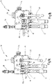
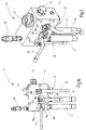
- Figures 1a to 1c each show a side view of a valve block 10, on the underside of which a first gas safety valve 12 and a second gas safety valve 14 are arranged.
- the gas safety valves 12, 14 are each fitted with a plug of a ball valve 50, 52 (see Fig. Figure 3a , b) assigned.
- the chicks of the ball valves 50, 52 are arranged separately from one another via a first hand lever 16 and a second hand lever 18 between an open switch position and a closed switch position and can be switched back and forth.
- switching position of the two hand levers 16, 18, these are each in the vertical direction, parallel to the cylindrical gas safety valves 12, 14, aligned and therefore shown in their open switching position.
- the associated hand lever 16 or 18 In the closed switch position, the associated hand lever 16 or 18 is aligned horizontally, as in Fig. 1b for the second hand lever 18 and in 1c shown for the first hand lever 16. While the hand lever 16 is designed to run straight, the other hand lever 18 is cranked so that it can be swiveled over the hand lever 16 if necessary (see Fig. 2 ).
- the connection to the gas side 45 is one in the Figures 1a to 1c not shown pressure accumulator 42 (see Figure 3a and 3b ) separated via the associated ball valve 50 or 52 and the removal of the associated gas safety valve 12 or 14 is possible in a safe manner, which will be explained in more detail below.
- a third hand lever 20 is arranged on the outside of the valve block 10, via which a plug of a further third ball valve 54 (see Fig. Figure 3a , b) is operable.
- the connection 22 is in the direction of the Figures 1a, b , c and 2 arranged on the underside of the cuboid valve block 10.
- a filling and testing connection point 24 for a gas-side filling and testing device not shown in detail
- a pressure connection 26 for a connection of the pressure accumulator 42.
- a measuring device 28 in the form of an electrical pressure transducer is also provided on the upper side of the valve block 10 .
- the side surface of the valve block 10 shown on the right is a pressure gauge connection 34 for a pressure gauge 44 (see Fig. 3a to 6 ) educated.
- the first and the second hand lever 16, 18 are each connected to a circular control disk 30a, 30b, which are each arranged coaxially to the axis of rotation of the associated hand lever 16, 18 on the front face of the valve block 10.
- the third hand lever 20 has a conventional disk 30c for rotation limitation.
- the ring-shaped control discs 30a, 30b for the hand levers 16, 18 each have a segmented and concave cutout 32a, 32b with an arcuate contour.
- the two cutouts 32a, 32b are arranged opposite one another.
- the design and arrangement of the cutouts 32a, 32b is selected such that when the second hand lever 18 is moved clockwise into the closed switch position, comparable to the representation according to FIG Fig. 1b , the second control disk 30b is positively moved on the outer circumference with its outer contour, which is convex to this extent, into the first, concave recess 32a on the first control disk 30a of the first hand lever 16 .
- the first hand lever 16 is mechanically locked in the open, vertical switch position shown by the control disks 30a, 30b.
- the first control disk 30a with its convex or arcuate outer circumference is moved clockwise into the closed switch position when the first hand lever 16 is moved, as in FIG 1c shown, moved into the second, concave cutout 32b on the second control disk 30b and accordingly the second hand lever 18 in the 1c securely locked in the open, vertical switching position shown.
- Two stop limits 15a, 15b protruding like pins are also provided on the valve block 10, each of which defines the rotational movement of the associated hand lever 16, 18 by 90° into the open and the closed switching position and are formed adjacent to the cutout 32a, 32b of the respective control disk 30a, 30b Stop lugs interact.
- the pertinent limit stop is common with ball valves, so that this is not discussed in detail; in particular, individual details have been omitted from the figures for the sake of clarity.
- a stop limiter 15c for a lug formed on the control disk 30c is also shown, which limits the corresponding rotational movement of the third hand lever 20.
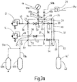
- Figure 3a shows a hydraulic circuit diagram for a first exemplary embodiment of the valve block 10 with a first valve connection 36 (see Fig. 1a ) for the first gas safety valve 12 and a second valve connection 38 (see Fig. 1b ) for the second gas safety valve 14.
- Two additional pressure accumulators 40a, 40b designed as gas accumulators in the form of conventional nitrogen refill bottles, are connected to the valve block 10 at the supply connection 22, for example.
- a pressure reservoir 42 also connected to the pressure port 26 , designed as a pressure vessel in the form of a nitrogen bottle that is filled exclusively with a gaseous pressure medium.
- the manometer 44 is connected to the manometer connection 34 and the measuring device 28 is connected to a measuring connection 48 .
- the pressure gauge 44 and the measuring device 28 of conventional design are connected to the associated connections 34 and 48 on the valve block 10 via quick-acting couplings 46a, 46b to carry fluid and pressure.
- the pressure accumulator 42 can be filled with nitrogen from the reloading cylinders 40a, 40b. The filled reservoir 42 can then be removed from the valve block 10 and a new reservoir 42 can be filled again.
- a supply network (not shown) could also take the place of the individual storage bottles 40a, 40b, from which the storage 42 can then be filled.
- a pressure accumulator 42 in the form of a gas storage bottle shown as an example, a large number of such gas-carrying storage systems can also be connected to the connection 26 of the valve block 10 (not shown).
- valve block 10 In the valve block 10 are several interconnected fluid connections between the first valve port 36, the second valve port 38, the supply port 22, the pressure port 26, the Filling and test connection point 24, the measuring connection 48 and the pressure gauge connection 34 are formed.
- the connections are made as bores in the valve block 10 made of a metal material.
- a first connecting section 21 leads from the first valve port 36 to a first crossing point 23, and a second connecting section 25 leads from the second valve port 38 to a second crossing point 27.
- the first crossing point 23 and the second crossing point 27 are arranged in a third connecting section 29, which extends from the measuring port 48 runs to a third crossing point 31 inside the valve block 10 .
- a fourth connection section 33 runs from the supply connection 22 to the pressure connection 26.
- the third crossing point 31 and a fourth crossing point 35 are arranged.
- the fourth crossing point 35 is the end of a filling and testing connection 37 beginning at the filling and testing connection point 24.
- a fifth crossing point 39 is arranged in the filling and testing connection 37, which represents the end of a fifth connection section 41 beginning at the first crossing point 23.
- a sixth crossing point 43 is arranged in the first connecting section 21 between the first valve connection 36 and the first crossing point 22 , which represents the end of a sixth connecting section 45 beginning at the manometer connection 34 .
- first line section 47 between the first gas safety valve 12 and the first valve port 36
- second line section 49 between the second gas safety valve 14 and the second valve port 38
- third line sections 51, 51a, 51b between the other pressure accumulators 40a, 40b and the supply port 22
- fourth line section 53 between the pressure accumulator or gas storage bottle 42 and the pressure connection 26
- fifth line sections 55a, 55b, 55c between the measuring device 28 and the measuring connection 48 and continuing from the measuring device 28 and sixth line sections 57a, 57b between the pressure gauge 44 and the pressure gauge connection 34 are present.
- the first ball valve 50 is arranged in the first connecting section 21 and the second ball valve 52 is arranged in the second connecting section 25.
- the third ball valve 54 is arranged between the third 31 and fourth crossing point 35, and a check valve 56 is connected parallel to this in the fifth connecting section 41 between the first 23 and fifth crossing point 39, which valve opens in the direction of the first crossing point 23 .
- the individual ball valves 50, 52, 54 are actuated individually by hand via the associated hand levers 16, 18, 20. From the fourth crossing point 35 arranged adjacent to the pressure connection 26, the filling and testing connection 37 leads directly to the filling and testing connection point 24.
- Figure 3b is essentially identical to Figure 3a and differs from this solution shown in that instead of a gas storage bottle 42 designed as a pressure container, a pressure accumulator 42 designed as a hydraulic accumulator in the form of a piston accumulator is connected to the pressure connection 26 of the valve block 10 .
- a pressure accumulator 42 designed as a hydraulic accumulator in the form of a piston accumulator is connected to the pressure connection 26 of the valve block 10 .
- a hydraulic supply system 43 is connected as an example, regularly consisting of a hydraulic working circuit, such as a motor-pump unit, a storage tank, hydraulic consumers, control and monitoring devices, etc. (not shown).
- This safety function is also implemented when the other pressure accumulators 40a, 40b are separated on the gas side from the gas side 45 of the pressure accumulator 42 by closing the other third ball valve 54.
- the pressure is equalized via the non-return valve 56, which opens in the direction of the two gas safety valves 12, 14 and to this extent the associated, working gas regularly leading in the form of nitrogen gas, releases connections in the valve block 10 for the purpose of pressure reduction.
- the piston 49 of the pressure accumulator 42 designed as a piston accumulator separates the gas side 45 from the liquid side 47, which leads to the supply system 43.
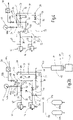
- the inside 4 shown circuit diagram for a second embodiment of the security system differs from that in the Figure 3a and 3b shown first embodiment in that instead of the two ball valves 50, 52 only a 3-way ball valve 58 in the connections from the gas safety valves 12, 14 to the respective pressure accumulator 42 is arranged is. Due to the arrangement of the 3-way ball valve 58, the wiring of the connections in the valve block 10 is modified in such a way that the first connection section 21 and the second connection section 25 each end at the ball valve 58 and from this a common connection section 59 to a common crossing point 61 in the third Connecting section 29 leads.
- the pressure gauge 44 is also connected to the third connection portion 29 via the sixth connection portion 45 .
- the wiring of the fourth connection section 33, the fifth connection section 41 and the filling and test connection 37 are unchanged.
- the pressure accumulators 40a, 40b, 42 are in 4 not shown for the sake of simplicity.
- the bottles 40a, 40b also do not necessarily have to be connected to the connection 22, which then has to be closed if it is unoccupied.
- the safety functions with the two gas safety valves 12, 14 and the associated ball valves 50, 52 are also reduced if only one corresponding pressure accumulator 42 is connected to the connection 26 of the valve block 10.
- the circuit diagram shown in the form of a hydraulic circuit diagram for a third exemplary embodiment of the safety system includes a first monitoring device 60 in the first connecting section 21 for electrically or electronically monitoring one connection from the first gas safety valve 12 to the pressure accumulator 42 and a second comparable monitoring device 62 in the second connecting section 25 for monitoring the other connection from the second gas safety valve 14 to the pressure accumulator 42 at connections 3, 2 of the 3-way ball valve 58 is formed. Otherwise, the representation corresponds to figure 5 essentially the representation according to the 4 .
- FIG. 6 circuit diagram for an embodiment of a safety system, which is not part of the invention, only one gas safety valve 12 is provided and only one monitoring device 60, as presented above, in the first connection section 21 for monitoring the one connection from the gas safety valve 12 to the pressure accumulator 42 on the associated ball valve 50 present.
- This monitoring device 60 can optionally monitor the open and/or closed position of the ball valve 50 electrically or electronically.
- the representation of 6 differs from that in the Figure 3a and 3b shown first embodiment in particular that the second gas safety valve 14, the second line section 49, the second valve port 38, the second connecting portion 25 together with the second crossing point 27 and the second ball valve 52 are omitted.
- a redundant mechanical locking or valve control concept is implemented in the exemplary embodiments of the safety system shown.
- the two associated 2-way ball valves 50, 52 can be mutually blocked in the direction of their respective horizontal closed position via the control disks 30a, 30b, so that only one ball valve 50 or 52 can reach its blocked position at a time, which means that the gas-carrying safety function is always only one of the two connected gas safety valves 12 or 14 overrides.
- the valve control concept according to the 4 operator guidance is achieved in the sense that, regardless of the operator's will, at least as seen from the valve position of the valve 58, a gas safety valve 12, 14 is always kept in its safety function.
- an electrical or electronic monitoring concept is implemented via at least one monitoring device 60, 62 on the 3-way ball valve 58 or on a ball valve 50. It is understood that combinations of such a monitoring concept according to the Figures 5 and 6 with a mechanical locking or valve control concept according to the Figure 3a , 3b and 4 can be combined with one another on the valve block 10 for reasons of redundancy.
- the blocking of the gas connection from the gas safety valve 12, 14 to the respective pressure accumulator 42 can be monitored via at least one monitoring device 60, 62, with the monitoring device 60, 62 generating a corresponding control and/or monitoring signal for a higher-level control device (not shown). can.
- the active replacement of a gas safety valve 12, 14 can be monitored manually on the valve block 10 and the valves 50, 52, 58 can be brought into the open or closed switching position as required.
- the gas side 45 of the respective pressure accumulator 42 can be checked via a filling and testing device 28 (not shown) to be connected to the filling and testing connection point 24 and optionally refillable.
- the third ball valve 54 remains open so that the working gas from the gas supply of the other pressure accumulators 40a, 40b can flow via the third line sections 51, 51a, 51b to can flow to the supply port 22, further via the fourth connecting section 33 to the pressure port 26 and further via the fourth line section 53 to the pressure accumulator 42 if necessary.
- the associated pressure profile can be monitored via the pressure gauge 44 connected to the pressure gauge connection 34 .
- the pressure in the safety system can be monitored electrically via the pressure transducer 28 . If the gas supply in the respective additional pressure accumulator 40a, 40b also has to be filled up, assuming that the additional pressure accumulators 40a, 40b are also connected to the valve block 10 via the connection point 22, this happens simultaneously with the gas side 45 of the respective pressure accumulator when the ball valve 54 is open 42 and, if necessary, with the ball valve 54 closed via the non-return valve 56. The relevant filling via the connection point 24 then continues until the pressure equilibrium established between the further pressure accumulators 40a, 40b, the refilling device at the connection point 24 and the respective pressure accumulator 42 the check valve 56 increasingly reaches its closed position.
- FIG. 7a and 7b An alternative embodiment of the security system is in the Figure 7a and 7b shown, the system according to Figure 7a is not part of the invention.
- the valve block 10 is compared to that in the Figures 1a to 1c shown embodiment designed comparatively small and encloses one in the perspective view of Figure 7a and 7b not shown 3-way ball valve.
- the ball valve can be actuated between its switch positions via a hand lever 16 rotatably arranged on the valve block 10 .
- the valve block 10 with the components arranged thereon forms a separate structural unit which is arranged on an end face 64 of a pressure accumulator 42 .
- a connecting piece 66 bent at right angles is inserted into a passage opening on the end face 64 , the valve block 10 being firmly connected to the connecting piece 66 .
- a gas safety valve 12 and a bursting disk 68 are arranged on the valve block 10 .
- the gas safety valve 12 and the bursting disc 68 are aligned horizontally and are arranged on opposite sides of the valve block 10 .
- the bursting disk 68 has the function that when the gas safety valve 12 is connected, this is kept free from damage in the event of excessive pressure loads due to the rupturing of the bursting disk 68 .
- a gas-carrying connection between the gas safety valve 12 and the pressure accumulator 42 can be blocked or released via the 3-way ball valve arranged in the valve block 10 .
- the 3-way ball valve has an L or T bore, with the central connection leading to the pressure accumulator 42 and the gas safety valve 12 and/or the bursting disc 68 being attached to the other connections.
- the second variant of the safety system shown differs from that in Figure 7a
- the first variant shown is that instead of the bursting disc 68 a second gas safety valve 14 is arranged on the valve block 10 .
- This has the advantage that when removing one of the two gas safety valves 12, 14 by the respective other gas safety valves 14, 12 remaining on the valve block 10 ensure a continuous safety function.
Landscapes
- Engineering & Computer Science (AREA)
- Mechanical Engineering (AREA)
- General Engineering & Computer Science (AREA)
- Physics & Mathematics (AREA)
- Fluid Mechanics (AREA)
- Chemical & Material Sciences (AREA)
- Analytical Chemistry (AREA)
- Filling Or Discharging Of Gas Storage Vessels (AREA)
- Fluid-Pressure Circuits (AREA)
- Supply Devices, Intensifiers, Converters, And Telemotors (AREA)
Description
- Die Erfindung betrifft ein Sicherheitssystem mit den Merkmalen im Oberbegriff von Anspruch 1.
- Ein derartiges Sicherheitssystem findet in unterschiedlichen hydraulischen Versorgungssystemen Anwendung und ist beispielsweise aus dem Produktkatalog "Speichertechnik" mit der Nr. D 3.553.4/03.16 der Firma HYDAC INTERNATIONAL bekannt. Die bekannte Lösung dient dem Befüllen und Prüfen von Hydro-Speicheranlagen mit sog. Nachschaltausführung. Hierzu weist der bekannte Ventilblock verschiedene Fluidanschlüsse auf, insbesondere für den Anschluss einer Füll- und Prüfeinrichtung, eines Manometers, von nachgeschalteten Stickstoffflaschen, eines Druckspeichers in Form eines Hydrospeichers sowie mindestens eines Gassicherheitsventils. Im Betrieb des Ventilblocks ist der Hydrospeicher, vorzugsweise in Form eines Kolbenspeichers, mit seiner Gasseite mit dem Gassicherheitsventil permanent verbunden. Die Flüssigkeitsseite des Hydrospeichers, die über ein Trennelement, wie einem in einem Speichergehäuse längsverfahrbar geführten Trennkolben, von der Gasseite separiert ist, ist an ein hydraulisches Versorgungssystem, beispielsweise in Form eines üblichen hydraulischen Arbeitskreises, angeschlossen. Ferner ist in dem Ventilblock ein Absperrventil vorhanden, das in seiner geöffneten Stellung den Fluidweg zwischen den möglicherweise angeschlossenen, nachgeschalteten Stickstoffflaschen und dem Hydrospeicher für eine gasführende Verbindung mit dem Stickstoffgas freigibt und das in seiner geschlossenen Stellung diesen Fluidweg sperrt.
- Bei Abnahme des jeweiligen Gassicherheitsventils vom Ventilblock, beispielsweise im Rahmen von Wartungs- oder Reparaturarbeiten, ist dann stets das gesamte, unter einem Betriebsdruck stehende Arbeitsgas aus dem Sicherheitssystem abzulassen, wobei der jeweils angeschlossene Hydrospeicher und/oder die jeweils angeschlossenen Stickstoffflaschen zu schließen sind und zumindest Teile einer angeschlossenen Hydraulikanlage müssen entsprechend drucklos gemacht werden. Bei anschließender Wiederinbetriebnahme des Sicherheitssystems samt jeweils zugehörigem Gassicherheitsventil und entsprechend angeschlossenen Druckspeichern sind die vorstehend angesprochenen Stilllegungsschritte wieder rückgängig zu machen.
- Die
EP 2 857 727 A1 beschreibt ein Sicherheitssystem mit den Merkmalen im Oberbegriff von Anspruch 1 mit einem Ventilblock, an den mindestens ein Gassicherheitsventil in abnehmbarer Weise angeschlossen ist, mit mindestens einem ansteuerbaren Ventil im oder am Ventilblock und mit mindestens einem ein gasförmiges Druckmedium aufnehmenden Druckspeicher, der an den Ventilblock in gleichfalls abnehmbarer Weise angeschlossen ist, wobei eine zumindest abschnittsweise innerhalb des Ventilblocks verlaufende gasführende Verbindung zwischen dem jeweils angeschlossenen Druckspeicher und dem jeweils angeschlossenen Gassicherheitsventil mittels des Ventils sperr- oder freigebbar ist. - Weitere Sicherheitssysteme gehen aus der
US 4 076 176 und derFR 3 024 204 - Ausgehend von diesem Stand der Technik stellt sich die Erfindung die Aufgabe, ein Sicherheitssystem mit verbesserter Funktionalität und zur Ressourcenschonung zu schaffen.
- Eine dahingehende Aufgabe löst ein Sicherheitssystem mit den Merkmalen des Patentanspruchs 1 in seiner Gesamtheit. Vorteilhafte Ausgestaltungen der Erfindung sind Gegenstand der Unteransprüche.
- Gemäß dem Kennzeichen von Anspruch 1 ist vorgesehen, dass an den Ventilblock mindestens zwei Gassicherheitsventile angeschlossen sind, und dass mittels einer Sicherheitseinrichtung, die das ansteuerbare Ventil umfasst, gewährleistet ist, dass zum Abnehmen eines Gassicherheitsventils vom Ventilblock die gasführende Verbindung zum jeweils angeschlossenen Druckspeicher unterbrochen ist und die zu mindestens einem anderen Gassicherheitsventil führende Verbindung derart aufrechterhalten bleibt, dass eine permanente gasführende Verbindung zwischen diesem jeweiligen Druckspeicher und diesem jeweils anderen Gassicherheitsventil während des Wechselvorgangs des einen Gassicherheitsventils und dessen erneuter Inbetriebnahme hergestellt ist.
- Dergestalt lässt sich der Betrieb einer hydraulischen, zumindest teilweise gasführenden Anlage aufrecht erhalten, auch wenn ein Gassicherheitsventil vom Ventilblock abgenommen ist, da das am Ventilblock sicherheitshalber verbleibende eine Gassicherheitsventil die angesprochenen Sicherheitsfunktionen vollständig übernimmt.
- Dadurch, dass eine zumindest abschnittsweise innerhalb des Ventilblocks verlaufende gasführende Verbindung zwischen dem jeweils angeschlossenen Druckspeicher und dem jeweils angeschlossenen Gassicherheitsventil mittels des Ventils sperr- oder freigebbar ist, ist eine besonders hohe Sicherheit erreicht. Das jeweilige Gassicherheitsventil lässt sich im Bedarfsfall vom Ventilblock abnehmen, sofern das zugehörige Ventil im oder am Ventilblock in seine Sperrstellung gebracht und insoweit mit Sicherheit von dem jeweils angeschlossenen Druckspeicher gasseitig entkoppelt ist, der aus einem Hydrospeicher oder einem Gasspeicher, wie einer Stickstoffflasche oder einem sonstigen, zumindest teilweise gasführenden Druckbehälter, wie einem Vorratstank oder dergleichen, gebildet ist.
- Das erfindungsgemäße Sicherheitssystem eröffnet die Möglichkeit, das am Ventilblock des Sicherheitssystems angeschlossene Gassicherheitsventil über ein zugeordnetes, ansteuerbares Ventil abzusperren, ohne dabei wesentliche Gasverluste auf Seiten der jeweiligen am Ventilblock angeschlossenen Druckspeicheranlage zu erleiden und ohne dass hydraulische Anlageteile drucklos zu machen wären.
- Die bei Reparatur- und/oder Wartungsarbeiten erforderliche Abnahme eines Gassicherheitsventils vom Ventilblock des Sicherheitssystems lässt sich schnell sowie kostengünstig durchführen und zeitlich aufwändige Entleer- und Befüllvorgänge auf der Gasseite einer insoweit angeschlossenen Anlage mit dem jeweiligen Druckspeicher können entfallen, was insoweit Ressourcen schonend ist. Dies hat so keine Entsprechung im Stand der Technik.
- Druckspeicher im Sinne der Erfindung umfassen sämtliche zur Aufnahme eines Fluids, insbesondere eines Gases, geeigneten und eingesetzten Behältnisse, wie Druckbehältnisse, Hydrospeicher, Gasflaschen, insbesondere Stickstoffflaschen, und dergleichen. Es versteht sich, dass der im erfindungsgemäßen Sicherheitssystem eingesetzte Druckspeicher nicht auf die in einzelnen Bereichen üblichen Sprachdefinitionen eingeschränkt ist.
- Bei einer bevorzugten Ausführungsform des erfindungsgemäßen Sicherheitssystems ist der jeweilige Druckspeicher ein Druckbehälter, der ausschließlich mit dem gasförmigen Druckmedium befüllt oder befüllbar ist, wie eine Stickstoffflasche oder ein Hydrospeicher, insbesondere in Balg-, Membran-, Speicher- oder Kolbenausführung, dessen in einem Speichergehäuse aufgenommenes Trennglied eine Gasseite von einer Flüssigkeitsseite trennt. Dergestalt lassen sich mit nur einem Sicherheitssystem auch verschiedene Arten von Druckspeichern, die nur an einen Ventilblock angeschlossen sind, sicher beherrschen, was regelmäßig der Fall ist, wenn auf einer Seite des Ventilblocks mindestens ein Hydrospeicher als Druckspeicher an eine hydraulische Anlage angeschlossen ist und auf derselben oder einer anderen Seite des Ventilblocks zusätzliche Stickstoffflaschen als Vorrats- oder Nachschaltflaschen angeschlossen sind, die bei hergestellter Fluidversorgung den Hydrospeicher auf seiner Gasseite auch im Betrieb desselben nachladen oder dessen Vorspannung auf seiner Gasseite im Betrieb erhöhen können.
- Mit dem erfindungsgemäßen Sicherheitssystem ist insbesondere gewährleistet, dass bei einer Inbetriebnahme und beim fortlaufenden Betrieb eines hydraulischen Versorgungssystems in jedem Fall das auf einen maximalen Ansprechdruck eingestellte Gassicherheitsventil permanent mit der Gasseite des von seiner Flüssigkeitsseite her an ein hydraulisches System oder eine Anlage angeschlossenen Druckspeichers beispielsweise in Form eines Hydrospeichers verbunden bleibt. Insbesondere bei mehrfach am Ventilblock eingesetzten Gassicherheitsventilen lässt sich zu Reinigungsund/oder Wartungszwecken eines solchen Gassicherheitsventils dieses vom Ventilblock abnehmen, während das jeweils andere, am Ventilblock verbleibende Gassicherheitsventil die beschriebene Sicherheitsfunktion für das hydraulische Versorgungssystem nebst seinen Anlageteilen weiter wahrnimmt. Regelmäßig sind solche Gassicherheitsventile aus Druckbegrenzungsventilen gebildet, deren zur Umgebung führende Gasaustrittsseite von einem Netzgitter oder einem Sieb abgedeckt ist, um etwaig in der Nähe sich aufhaltende Personen im Sicherheitsfall von dem abströmenden Druckgas hohen Druckes zu schützen.
- Bei einer bevorzugten Ausführungsform des erfindungsgemäßen Sicherheitssystems liegt der Sicherheitseinrichtung ein mechanisches Verriegelungskonzept, ein mechanisches Steuerkonzept, ein elektrisches Überwachungskonzept oder ein chipgesteuertes Betätigungskonzept für das jeweils ansteuerbare Ventil zugrunde. Durch die anforderungsgerechte, an die jeweilige Anwendung angepasste Ausgestaltung der Sicherheitseinrichtung ist im laufenden Betrieb bei geringer Stör- und Fehleranfälligkeit eine sichere Absperrung des Druckspeichers beispielsweise vor Abnahme eines zugehörigen Gassicherheitsventils gewährleistet. Mechanische Konzepte für die Verriegelung oder die Ventilsteuerung bieten den Vorteil einer hohen Robustheit sowie einer geringen Wartungsintensität. Ein elektrisches oder chipgesteuertes Konzept für die Überwachung oder die Betätigung bietet den Vorteil eines geringen Bauraumerfordernisses sowie die Möglichkeit einer Fernüberwachung bei Einsatz einer entsprechenden Datenübertragung.
- Bei einer weiteren bevorzugten Ausführungsform des erfindungsgemäßen Sicherheitssystems sind für die Realisierung des mechanischen Verriegelungskonzepts zwei, vorzugsweise von Hand betätigbare, Kugelhähne vorgesehen, die jeweils an ein zuordenbares Gassicherheitsventil gasführend angeschlossen sind und die Steuerscheiben tragen, die im gegenseitig verriegelten Zustand sicherstellen, dass ein Kugelhahn in seiner geöffneten Stellung das zugehörige Gassicherheitsventil mit dem Druckspeicher über eine Verbindung gasführend verbindet und der andere Kugelhahn in seiner Sperrstellung für ein Entfernen des zugehörigen Gassicherheitsventils, beispielsweise zu Austausch- oder Wartungszwecken, vom Ventilblock eine zugehörige andere Verbindung zum jeweiligen Druckspeicher sperrt.
- Die Steuerscheiben sind integraler Bestandteil einer mechanischen Verriegelung der Betätigungselemente der Kugelhähne und vorzugsweise an einer Außenseite des Ventilblocks angeordnet. Sobald ein Kugelhahn gesperrt wird zur Abnahme des zugehörigen Gassicherheitsventils, wird die zugehörige Steuerscheibe derart mit zumindest einer Steuerscheibe eines weiteren Gassicherheitsventils verriegelt, dass das weitere Gassicherheitsventil in der geöffneten, betriebssicheren Stellung blockiert und sicher gehalten ist. Somit ist bei Abnahme und Entfernen eines Gassicherheitsventils mindestens ein funktionstüchtiges weiteres Gassicherheitsventil an den Ventilblock in seiner Offenstellung angeschlossen, das dann ausschließlich die Sicherheitsfunktion wahrnimmt.
- Bei einer weiteren bevorzugten Ausführungsform der Erfindung ist mittels zweier Handhebel der Kugelhähne, ausgehend von einer gemeinsamen Öffnungsrichtung, je eine der Steuerscheiben in Richtung einer Schließstellung des Kugelhahns betätigbar, die außenumfangsseitig einen Ausschnitt aufweist, der mit einem korrespondierend ausgebildeten Ausschnitt am Außenumfang der anderen Steuerscheibe derart zusammenwirkt, dass eine Drehbewegung des jeweiligen Kugelhahns mittels des zugeordneten Handhebels ermöglicht oder blockiert ist. Besonders bevorzugt weist der jeweilige Ausschnitt eine bogenförmige Kontur mit einer Krümmung vergleichbar dem Außenumfang der Steuerscheibe auf. In einen derart geformten Ausschnitt greift die jeweils andere Steuerscheibe derart ein, dass der zugehörige Handhebel in der gewählten Stellung blockiert und ein unbeabsichtigtes oder gewolltes Ändern dieser Stellung nicht möglich ist.
- Die Gassicherheitsventile weisen eine zylindrische Grundform auf und sind an einer Unterseite des Ventilblocks angeordnet. Die Handhebel zur Betätigung der zugehörigen Kugelventile sind vorzugsweise an einer für eine Bedienperson zugänglichen Seite des Ventilblocks angeordnet, wobei in der Regel eine senkrechte Richtung die Öffnungsstellung und eine waagerechte Richtung die Schließstellung des zugehörigen Kugelhahns anzeigt. Besonders bevorzugt sind die Ausschnitte bei benachbarten Handhebeln derart angeordnet, dass in der Öffnungsstellung der beiden Handhebel die Ausschnitte benachbart und gegenüberliegend derart zueinander angeordnet sind, dass bei Bewegung des einen Handhebels in die Schließstellung die zugehörige Steuerscheibe in den Ausschnitt an der anderen Steuerscheibe des anderen Handhebels hinein bewegt wird und dabei deren Bewegung gleichfalls in die Schließstellung blockiert.
- Vorzugsweise sind zwei oder mehr Gassicherheitsventile nebeneinander, eine Reihe bildend, am Ventilblock angeordnet. Dementsprechend sind zwei bzw. mehr Handhebel mit zugehörigen Steuerscheiben nebeneinander, eine Reihe bildend, an der Seite des Ventilblocks angeordnet.
- Weiter ist vorteilhaft, dass die Steuerscheibe mit einer Anschlagbegrenzung am Ventilblock derart zusammenwirkt, dass der Handhebel aus einer Öffnungsrichtung parallel zu der Längsrichtung des jeweiligen Gassicherheitsventils um 90° in eine Sperrstellung quer zu dieser Längsausrichtung und umgekehrt verschwenkbar ist. Hieraus ergibt sich der Vorteil einer fehlerfreien Bedienung beim Verschwenken des jeweiligen Handhebels in eine seiner Stellungen.
- Bei einer weiteren bevorzugten Ausführungsform des erfindungsgemäßen Sicherheitssystems ist für die Realisierung des mechanischen Steuerkonzepts als steuerbares Ventil ein 3-Wege-Kugelhahn eingesetzt, der in seiner einen Schaltstellung ein Gassicherheitsventil über eine Verbindung mit dem Druckspeicher gasführend verbindet und ein anderes Gassicherheitsventil durch Sperren einer zugehörigen anderen Verbindung vom Druckspeicher entkoppelt, wobei in einer weiteren Schaltstellung das andere Gassicherheitsventil über die andere Verbindung mit dem Druckspeicher gasführend verbunden und das eine Gassicherheitsventil durch Sperren der einen Verbindung entkoppelt ist. Durch den Einsatz nur eines 3-Wege-Kugelhahns können zwei separate Kugelhähne für die beiden Gassicherheitsventile entfallen. Unabhängig von der Schaltstellung des 3-Wege-Kugelhahns ist dann aber ein Gassicherheitsventil an den Druckspeicher angeschlossen und ein Gassicherheitsventil hiervon getrennt, so dass zumindest immer ein Gassicherheitsventil die Sicherheitsfunktion für den Druckspeicher übernimmt.
- Bei einer weiteren bevorzugten Ausführungsform des erfindungsgemäßen Sicherheitssystems ist für die Realisierung des elektrischen Überwachungskonzepts mittels einer Sensorik die Position des jeweils ansteuerbaren Ventils auf seine Öffnungs- und/oder Schließstellung hin überwacht, und ein Betrieb des hydraulischen Versorgungssystems wird von einer übergeordneten Steuerung erst dann ermöglicht, wenn die Sensorik feststellt und an die Steuerung übermittelt, dass die jeweilige gasführende Verbindung zwischen Gassicherheitsventil und Druckspeicher über das steuerbare Ventil tatsächlich freigegeben ist. Hieraus ergibt sich der Vorteil, dass ein Öffnen oder Sperren der gasführenden Verbindung "automatisch" feststellbar ist. Mittels einer zusätzlichen optischen Anzeige, beispielsweise an einer Außenseite des Ventilblocks angebracht, kann einer Bedienperson die Freigabe zur Abnahme des Gassicherheitsventils angezeigt werden, wenn das andere Gassicherheitsventil die Sicherheitsfunktion wahrnimmt.
- Bei einer weiteren bevorzugten Ausführungsform des erfindungsgemäßen Sicherheitssystems ist für die Realisierung des chipgesteuerten Betätigungskonzepts ein Steuerchip vorgesehen, der an der Steuerung des hydraulischen Versorgungssystems eingesetzt deren Betrieb erst ermöglicht, bei dessen Entfernen das Versorgungssystem aber stillsetzt und bei dessen Einsatz am steuerbaren Ventil das jeweils zuordenbare Gassicherheitsventil dann gasseitig vom Druckspeicher durch Sperren der zugehörigen Verbindung entkoppelt. Umgekehrt ist ein Betrieb des hydraulischen Versorgungssystems erst möglich, wenn der Steuerchip nach Entnahme das Gassicherheitsventil wieder in seine Öffnungsstellung freigibt und dieser Chip an der Steuerung erneut eingesetzt den Betrieb der angeschlossenen hydraulischen Anlage wieder ermöglicht.
- Weiter ist vorteilhaft, dass der Ventilblock mindestens einen weiteren Versorgungsanschluss aufweist, über den mindestens ein weiterer Druckspeicher, vorzugsweise ein Gasdruckspeicher, anschließbar ist, der über ein innerhalb des Ventilblocks angeordnetes Sperrventil in seiner geöffneten Stellung mit dem jeweiligen Druckspeicher gasführend verbunden, vorzugsweise an die Gasseite eines Hydrospeichers angeschlossen, ist. Über den weiteren Versorgungsanschluss kann dann insbesondere Gas aus dem Gasvorrat der Speicherflasche entnommen und auf die Gasseite des Hydrospeichers geleitet werden, um dergestalt das Arbeitsvermögen dieses Hydrospeichers zu erhöhen.
- Weiter ist vorteilhaft, dass der Ventilblock zumindest eine weitere Anschlussstelle aufweist, an die eine Füll- und Prüfeinrichtung anschließbar ist, die über eine Füll- und Prüfverbindung im Ventilblock direkt mit dem Druckspeicher gasführend verbunden, vorzugsweise an die Gasseite eines Hydrospeichers in Form eines Kolbenspeichers angeschlossen, ist, und dass diese Füll- und Prüfverbindung über ein Rückschlagventil, das in Richtung des jeweiligen steuerbaren Ventils öffnet, an eine weitere Verbindung zwischen dem jeweiligen weiteren Druckspeicher und dem Druckspeicher angeschlossen ist. Über die Füll- und Prüfeinrichtung sind Eigenschaften des Gases, wie Temperatur und Druck des Gasvolumens, überwach- und erfassbar.
- Ist an den vorstehend bezeichneten Hydrospeicher auf seiner Flüssigkeitsseite in üblicher Weise ein hydraulisches Versorgungssystem angeschlossen, ist mit dem erfindungsgemäßen Sicherheitssystem gewährleistet, dass im Fall einer Betriebsstörung, wie sie auch durch einen Brand verursacht sein kann, es nicht ungewollt zu einer Druckerhöhung auf der Gasseite des Hydrospeichers kommen kann, da über die geöffnete Ventileinrichtung, respektive den in Öffnungsstellung befindlichen Kugelhahn sichergestellt ist, dass bei Überschreiten eines Maximaldrucks auf den das jeweilige Gassicherheitsventil eingestellt ist, Gas mit höherem Druck auf der Hydrospeicherseite in die Umgebung direkt entweichen kann. Dergestalt wird auch ein zu hoher Druck auf der Flüssigkeitsseite des Hydrospeichers und auf Seiten des Versorgungssystems, der zum Bersten von Anlageteilen führen könnte, unmittelbar abgebaut, so dass eine Gefährdung von Bedienpersonen an den Anlageteilen des Versorgungssystems ausgeschlossen ist. Das Sicherheitssystem gewährleistet dabei weiter, dass manuelle Fehlbedienungen, die zu einer ungewollten Stilllegung der Funktion des Gassicherheitsventils führen könnten, ausgeschlossen sind.
- Weitere Vorteile und Merkmale der Erfindung ergeben sich aus den Figuren und der nachfolgenden Beschreibung der Zeichnung. Die vorstehend genannten und die weiter angeführten Merkmale können erfindungsgemäß jeweils einzeln oder in beliebigen Kombinationen an einem erfindungsgemäßen Sicherheitssystem realisiert sein. Die in den Figuren gezeigten Merkmale sind rein schematisch und nicht maßstäblich zu verstehen. Es zeigen:
- Fig. 1a bis 1c
- jeweils eine Seitenansicht auf ein Ausführungsbeispiel eines Ventilblocks eines Sicherheitssystems mit unterschiedlichen Betätigungsstellungen von einzelnen Gassicherheitsventilen zugeordneten Handhebeln;
- Fig. 2
- eine perspektivische Ansicht des Ventilblocks aus
Fig. 1b ; - Fig. 3a und 3b
- jeweils einen Schaltplan für ein erstes Ausführungsbeispiel des erfindungsgemäßen Sicherheitssystems;
- Fig. 4
- einen Schaltplan für ein zweites Ausführungsbeispiel des erfindungsgemäßen Sicherheitssystems;
- Fig. 5
- einen Schaltplan für ein drittes Ausführungsbeispiel des erfindungsgemäßen Sicherheitssystems;
- Fig. 6
- einen Schaltplan für ein Ausführungsbeispiel eines weiteren Sicherheitssystems; und
- Fig. 7a und 7b
- jeweils eine perspektivische Ansicht eines weiterem Sicherheitssystems.
- Die Ausführungsformen der
Fig. 6 und7a dienen lediglich der Erläuterung des Hintergrundes der Erfindung und sind nicht Gegenstand eines Anspruches. -
Fig. 1a bis 1c zeigen jeweils in Seitenansicht einen Ventilblock 10, an dessen Unterseite ein erstes Gassicherheitsventil 12 und ein zweites Gassicherheitsventil 14 angeordnet sind. Den Gassicherheitsventilen 12, 14 ist jeweils ein im Gehäuse des Ventilblocks 10 vorhandenes Küken eines Kugelhahns 50, 52 (s.Fig. 3a ,b) zugeordnet. Die Küken der Kugelhähne 50, 52 sind über einen ersten Handhebel 16 bzw. einen zweiten Handhebel 18 voneinander getrennt zwischen einer geöffneten Schaltstellung und einer geschlossenen Schaltstellung hin und her schaltbar angeordnet. In der inFig. 1a gezeigten Schaltstellung der beiden Handhebel 16, 18 sind diese jeweils in senkrechter Richtung, parallel zu den zylinderförmigen Gassicherheitsventilen 12, 14, ausgerichtet und mithin in ihrer geöffneten Schaltstellung dargestellt. In der geschlossenen Schaltstellung ist der zugehörige Handhebel 16 oder 18 waagerecht ausgerichtet, wie inFig. 1b für den zweiten Handhebel 18 und inFig. 1c für den ersten Handhebel 16 gezeigt. Während der Handhebel 16 gerade verlaufend ausgeführt ist, weist der andere Handhebel 18 eine Kröpfung auf, so dass er im Bedarfsfall über den Handhebel 16 hinweg geschwenkt werden kann (s.Fig. 2 ). In der geschlossenen Schalt- oder Schließstellung ist die Verbindung zur Gasseite 45 eines in denFig. 1a bis 1c nicht gezeigten Druckspeichers 42 (s.Fig. 3a und3b ) über den zugehörigen Kugelhahn 50 oder 52 getrennt und die Abnahme des zugehörigen Gassicherheitsventils 12 bzw. 14 in sicherer Weise möglich, was im Folgenden noch näher erläutert werden wird. - Beabstandet zu den nebeneinander angeordneten Handhebeln 16, 18 ist ein dritter Handhebel 20 an der Außenseite des Ventilblocks 10 angeordnet, über welchen ein einem Versorgungsanschluss 22 zugeordnetes Küken eines weiteren dritten Kugelhahns 54 (s.
Fig. 3a ,b) betätigbar ist. Der Anschluss 22 ist dabei in Blickrichtung auf dieFiguren 1a, b ,c und 2 an der Unterseite des quaderförmigen Ventilblocks 10 angeordnet. In einer in denFig. 1a bis 1c rechts gezeigten Seitenfläche des Ventilblocks 10 ist eine Füll- und Prüfanschlussstelle 24 für eine nicht weiter gezeigte gasseitige Füll- und Prüfeinrichtung ausgebildet, und an der Oberseite des Ventilblocks 10 ist ein Druckanschluss 26 für einen Anschluss des Druckspeichers 42 vorhanden. Weiter ist eine Messeinrichtung 28 in Form eines elektrischen Druckmesswertumformers an der Oberseite des Ventilblocks 10 vorgesehen. An der in denFig. 1a bis 1c rechts gezeigten Seitenfläche des Ventilblocks 10 ist ein Manometeranschluss 34 für ein Manometer 44 (s.Fig. 3a bis 6 ) ausgebildet. Der erste und der zweite Handhebel 16, 18 sind jeweils mit einer kreisförmigen Steuerscheibe 30a, 30b verbunden, die jeweils koaxial zur Drehachse des zugehörigen Handhebels 16, 18 auf der vorderen Stirnseite des Ventilblocks 10 angeordnet sind. Der dritte Handhebel 20 weist eine übliche Scheibe 30c zur Drehbegrenzung auf. - Die ringförmig ausgebildeten Steuerscheiben 30a, 30b für die Handhebel 16, 18 weisen jeweils einen segmentweise und konkav geformten Ausschnitt 32a, 32b mit bogenförmiger Kontur auf. In der in
Fig. 1a gezeigten geöffneten Schaltstellung der beiden Handhebel 16, 18 sind die beiden Ausschnitte 32a, 32b einander gegenüberliegend angeordnet. Die Ausgestaltung und Anordnung der Ausschnitte 32a, 32b ist derart gewählt, dass bei Bewegen des zweiten Handhebels 18 im Uhrzeigersinn in die geschlossene Schaltstellung, vergleichbar der Darstellung nach derFig. 1b , die zweite Steuerscheibe 30b außenumfangsseitig mit ihrer insoweit konvexen Außenkontur in die erste, konkave Ausnehmung 32a an der ersten Steuerscheibe 30a des ersten Handhebels 16 zwangsläufig hinein bewegt wird. Hierdurch wird der erste Handhebel 16 in der gezeigten geöffneten, vertikalen Schaltstellung durch die Steuerscheiben 30a, 30b mechanisch verriegelt. In vergleichbarer Weise wird die erste Steuerscheibe 30a mit ihrem konvexen oder bogenförmigen Außenumfang bei Bewegung des ersten Handhebels 16 im Uhrzeigersinn in die geschlossene Schaltstellung, wie inFig. 1c gezeigt, in den zweiten, konkaven Ausschnitt 32b an der zweiten Steuerscheibe 30b hinein bewegt und dementsprechend der zweite Handhebel 18 in der inFig. 1c gezeigten geöffneten, vertikalen Schaltstellung sicher verriegelt. - Am Ventilblock 10 sind weiter zwei stiftartig vorstehende Anschlagbegrenzungen 15a, 15b vorgesehen, welche jeweils die Drehbewegung des zugehörigen Handhebels 16, 18 um 90° in die geöffnete und die geschlossene Schaltstellung festlegen und mit benachbart zum Ausschnitt 32a, 32b der jeweiligen Steuerscheibe 30a, 30b ausgebildeten Anschlagnasen zusammenwirken. Die dahingehende Anschlagbegrenzung ist bei Kugelhähnen üblich, sodass hierauf nicht mehr näher eingegangen wird; insbesondere wurden einzelne Details hierzu in den Figuren der besseren Übersichtlichkeit weggelassen. In
Fig. 2 ist weiter eine Anschlagbegrenzung 15c für eine an der Steuerscheibe 30c ausgebildete Nase dargestellt, welche die entsprechende Drehbewegung des dritten Handhebels 20 begrenzt. -
Fig. 3a zeigt einen hydraulischen Schaltplan für ein erstes Ausführungsbeispiel des Ventilblocks 10 mit einem ersten Ventilanschluss 36 (s.Fig. 1a ) für das erste Gassicherheitsventil 12 und einem zweiten Ventilanschluss 38 (s.Fig. 1b ) für das zweite Gassicherheitsventil 14. Am Versorgungsanschluss 22 sind beispielhaft zwei weitere Druckspeicher 40a, 40b, ausgebildet als Gasspeicher in Form üblicher Stickstoff-Nachladeflaschen, an den Ventilblock 10 angeschlossen. Weiter sind am Druckanschluss 26 ein Druckspeicher 42, ausgebildet als ausschließlich mit einem gasförmigen Druckmedium befüllter Druckbehälter in Form einer Stickstoffflasche angeschlossen. Am Manometeranschluss 34 ist das Manometer 44 und an einem Messanschluss 48 ist die Messeinrichtung 28 angeschlossen. Das Manometer 44 und die Messeinrichtung 28 üblicher Bauart sind über Schnellschlusskupplungen 46a, 46b mit den zugehörigen Anschlüssen 34 bzw. 48 am Ventilblock 10 fluid- und druckführend verbunden. Mit der Lösung nach derFig. 3a lässt sich unter anderem der Druckspeicher 42 aus den Nachladeflaschen 40a, 40b mit Stickstoff befüllen. Der befüllte Speicher 42 kann dann vom Ventilblock 10 befüllt entnommen und ein neuer Speicher 42 wiederum befüllt werden. Insoweit könnte auch an die Stelle der einzelnen Speicherflaschen 40a, 40b ein Versorgungsnetz (nicht dargestellt) treten, aus dem sich der Speicher 42 dann befüllen lässt. Anstelle eines exemplarisch dargestellten Druckspeichers 42 in Form einer Gasvorratsflasche lassen sich auch eine Vielzahl solcher gasführenden Speichersysteme an den Anschluss 26 des Ventilblocks 10 anschließen (nicht dargestellt). - Im Ventilblock 10 sind mehrere, miteinander verschaltete Fluidverbindungen zwischen dem ersten Ventilanschluss 36, dem zweiten Ventilanschluss 38, dem Versorgungsanschluss 22, dem Druckanschluss 26, der Füll- und Prüfanschlussstelle 24, dem Messanschluss 48 und dem Manometeranschluss 34 ausgebildet. Typischerweise sind die Verbindungen als Bohrungen in den aus einem Metallwerkstoff gefertigten Ventilblock 10 eingebracht. Vom ersten Ventilanschluss 36 führt ein erster Verbindungsabschnitt 21 zu einem ersten Kreuzungspunkt 23, vom zweiten Ventilanschluss 38 ein zweiter Verbindungsabschnitt 25 zu einem zweiten Kreuzungspunkt 27. Der erste Kreuzungspunkt 23 und der zweite Kreuzungspunkt 27 sind in einem dritten Verbindungsabschnitt 29 angeordnet, welcher vom Messanschluss 48 zu einem dritten Kreuzungspunkt 31 im Inneren des Ventilblocks 10 verläuft.
- Ein vierter Verbindungsabschnitt 33 verläuft vom Versorgungsanschluss 22 zum Druckanschluss 26. Im vierten Verbindungsabschnitt 33 sind der dritte Kreuzungspunkt 31 und ein vierter Kreuzungspunkt 35 angeordnet. Der vierte Kreuzungspunkt 35 ist das Ende einer an der Füll- und Prüfanschlussstelle 24 beginnenden Füll- und Prüfverbindung 37. In der Füllund Prüfverbindung 37 ist ein fünfter Kreuzungspunkt 39 angeordnet, welcher das Ende eines am ersten Kreuzungspunkt 23 beginnenden fünften Verbindungsabschnitts 41 darstellt. Im ersten Verbindungsabschnitt 21 ist zwischen dem ersten Ventilanschluss 36 und dem ersten Kreuzungspunkt 22 ein sechster Kreuzungspunkt 43 angeordnet, welcher das Ende eines am Manometeranschluss 34 beginnenden sechsten Verbindungsabschnitts 45 darstellt.
- Weiter sind ein erster Leitungsabschnitt 47 zwischen dem ersten Gassicherheitsventil 12 und dem ersten Ventilanschluss 36, ein zweiter Leitungsabschnitt 49 zwischen dem zweiten Gassicherheitsventil 14 und dem zweiten Ventilanschluss 38, dritte Leitungsabschnitte 51, 51a, 51b zwischen den weiteren Druckspeichern 40a, 40b und dem Versorgungsanschluss 22, ein vierter Leitungsabschnitt 53 zwischen dem Druckspeicher oder Gasvorratsflasche 42 und dem Druckanschluss 26, fünfte Leitungsabschnitte 55a, 55b, 55c zwischen der Messeinrichtung 28 und dem Messanschluss 48 sowie von der Messeinrichtung 28 weiterführend und sechste Leitungsabschnitte 57a, 57b zwischen dem Manometer 44 und dem Manometeranschluss 34 vorhanden.
- In den von den Gassicherheitsventilen 12, 14 zum Druckspeicher 42 führenden Verbindungen sind im ersten Verbindungsabschnitt 21 der erste Kugelhahn 50 und im zweiten Verbindungsabschnitt 25 der zweite Kugelhahn 52 angeordnet. In dem zum Druckspeicher 42 führenden vierten Verbindungsabschnitt 33 ist der dritte Kugelhahn 54 zwischen drittem 31 und viertem Kreuzungspunkt 35 angeordnet und parallel zu diesem ein Rückschlagventil 56 im fünften Verbindungsabschnitt 41 zwischen erstem 23 und fünftem Kreuzungspunkt 39 geschaltet, das in Richtung des ersten Kreuzungspunktes 23 öffnet. Die einzelnen Kugelhähne 50, 52, 54 werden über die zugehörigen Handhebel 16, 18, 20 einzeln von Hand betätigt. Vom benachbart zum Druckanschluss 26 angeordneten vierten Kreuzungspunkt 35 führt die Füll- und Prüfverbindung 37 direkt zur Füll- und Prüfanschlussstelle 24.
-
Fig. 3b ist im Wesentlichen identisch mitFig. 3a und unterscheidet sich von dieser gezeigten Lösung darin, dass anstelle einer als Druckbehälter ausgebildeten Gasvorratsflasche 42 ein als Hydrospeicher in Form eines Kolbenspeichers ausgebildeter Druckspeicher 42 an den Druckanschluss 26 des Ventilblocks 10 angeschlossen ist. An die Hydraulik- oder Flüssigkeitsseite 47 des als Kolbenspeicher ausgebildeten Druckspeichers 42 ist in der Darstellung derFig. 3b exemplarisch ein hydraulisches Versorgungssystem 43 angeschlossen, regelmäßig aus einem hydraulischen Arbeitskreis bestehend, wie einer Motor-Pumpeneinheit, einem Vorratstank, hydraulischen Verbrauchern, Steuer- und Überwachungseinrichtungen, etc. (nicht dargestellt). - Sobald der Druck auf der Gasseite 45 des Druckspeichers 42 ansteigt, bedingt durch eine unzulässige Druckerhöhung, beispielsweise hervorgerufen durch eine technische Störung im hydraulischen Versorgungssystem 43, wie einen Brand, wird bei Überschreiten eines Maximaldrucks auf der Gasseite 45 des Druckspeichers 42, der von dem Ansprechdruck der Gassicherheitsventile 12, 14 vorgegeben ist, deren Auslösen bewirkt und Gas kann von der Gasseite 45 des Druckspeichers 42 bei geöffneten Ventilen in Form der Kugelhähne 50, 52 über die Gassicherheitsventile 12, 14 solange abströmen, bis deren Ansprechdruck von beispielsweise 330 bar wieder erreicht respektive unterschritten ist. Diese Sicherheitsfunktion ist auch dann verwirklicht, wenn die weiteren Druckspeicher 40a, 40b gasseitig von der Gasseite 45 des Druckspeichers 42 durch Schließen des weiteren dritten Kugelhahns 54 getrennt sind. In diesem Fall erfolgt der Druckausgleich über das Rückschlagventil 56, das in Richtung der beiden Gassicherheitsventile 12, 14 öffnet und insoweit die zugehörigen, Arbeitsgas regelmäßig in Form von Stickstoffgas führenden, Verbindungen im Ventilblock 10 zwecks Druckabbau freigibt. Der Vollständigkeit halber sei noch erwähnt, dass der Kolben 49 des als Kolbenspeicher ausgebildeten Druckspeichers 42 die Gasseite 45 von der Flüssigkeitsseite 47, die zum Versorgungssystem 43 führt, voneinander separiert. Bei dem in
Fig. 3a ,3b jeweils gezeigten Ausführungsbeispiel des Sicherheitssystems ist durch die separat voneinander bedien- und schaltbaren Kugelhähne 50, 52 gewährleistet, das stets eines der Gassicherheitsventile 12 oder 14 über die zugehörige Verbindung gasführend mit dem Druckspeicher 42 verbunden ist, was wie dargelegt zum erwünschten Sicherheitsgewinn führt. - Der in
Fig. 4 gezeigte Schaltplan für ein zweites Ausführungsbeispiel des Sicherheitssystems unterscheidet sich von dem in denFig. 3a und3b gezeigten ersten Ausführungsbeispiel dadurch, dass anstelle der beiden Kugelhähne 50, 52 nur ein 3-Wege-Kugelhahn 58 in den Verbindungen von den Gassicherheitsventilen 12, 14 zum jeweiligen Druckspeicher 42 angeordnet ist. Aufgrund der Anordnung des 3-Wege-Kugelhahns 58 ist die Verschaltung der Verbindungen im Ventilblock 10 dahingehend modifiziert, dass der erste Verbindungsabschnitt 21 und der zweite Verbindungsabschnitt 25 jeweils am Kugelhahn 58 enden und von diesem ein gemeinsamer Verbindungsabschnitt 59 zu einem gemeinsamen Kreuzungspunkt 61 im dritten Verbindungsabschnitt 29 führt. Das Manometer 44 ist über den sechsten Verbindungsabschnitt 45 ebenfalls an den dritten Verbindungsabschnitt 29 angeschlossen. Die Verschaltung des vierten Verbindungsabschnitts 33, des fünften Verbindungsabschnitts 41 und der Füll- und Prüfverbindung 37 sind unverändert. Die Druckspeicher 40a, 40b, 42 sind inFig. 4 der Einfachheit halber nicht mehr dargestellt. Auch brauchen die Flaschen 40a, 40b nicht zwingend am Anschluss 22 angeschlossen sein, der insoweit unbesetzt dann zu verschließen ist. Die Sicherheitsfunktionen mit den beiden Gassicherheitsventilen 12, 14 und den zugehörigen Kugelhähnen 50, 52 ist auch dann reduziert, wenn nur ein entsprechender Druckspeicher 42 am Anschluss 26 des Ventilblocks 10 angeschlossen ist. Bei der 3-Wege-Kugelhahnlösung ist, unabhängig von der Drehstellung des Kükens des Kugelhahns 58, aber immer sichergestellt, dass ein Gassicherheitsventil 12 oder 14 in jedem Fall mit dem Druckspeicher 42 gasführend verbunden ist. Gefährliche Fehlbedienungen sind wie auch bei den vorher beschriebenen Lösungen dergestalt, ausgeschlossen. - Bei dem in
Fig. 5 dargestellten Schaltplan in der Art eines hydraulischen Schaltplans für ein drittes Ausführungsbeispiel des Sicherheitssystems sind eine erste Überwachungseinrichtung 60 im ersten Verbindungsabschnitt 21 zur elektrischen oder elektronischen Überwachung der einen Verbindung vom ersten Gassicherheitsventil 12 zum Druckspeicher 42 und eine zweite vergleichbare Überwachungseinrichtung 62 im zweiten Verbindungsabschnitt 25 zur Überwachung der anderen Verbindung vom zweiten Gassicherheitsventil 14 zum Druckspeicher 42 an Anschlüssen 3, 2 des 3-Wege-Kugelhahns 58 ausgebildet. Ansonsten entspricht die Darstellung derFig. 5 im Wesentlichen der Darstellung nach derFig. 4 . - Bei dem in
Fig. 6 gezeigten Schaltplan für ein Ausführungsbeispiel eines Sicherheitssystems, das nicht Teil der Erfindung ist, ist lediglich ein Gassicherheitsventil 12 vorgesehen und nur eine Überwachungseinrichtung 60, wie vorstehend vorgestellt, im ersten Verbindungsabschnitt 21 zur Überwachung der einen Verbindung vom Gassicherheitsventil 12 zum Druckspeicher 42 am zugehörigen Kugelhahn 50 vorhanden. Diese Überwachungseinrichtung 60 kann wahlweise elektrisch oder elektronisch die Öffnungs- und/oder Schließstellung des Kugelhahns 50 überwachen. Die Darstellung derFig. 6 unterscheidet sich von dem in denFig. 3a und3b gezeigten ersten Ausführungsbeispiel insbesondere darin, dass das zweite Gassicherheitsventil 14, der zweite Leitungsabschnitt 49, der zweite Ventilanschluss 38, der zweite Verbindungsabschnitt 25 samt zweitem Kreuzungspunkt 27 und der zweite Kugelhahn 52 entfallen. - Bei den in den
Fig. 3a ,3b und 4 gezeigten Ausführungsbeispielen des Sicherheitssystems ist ein redundantes mechanisches Verriegelungs- bzw. Ventilsteuerkonzept realisiert. Bei dem mechanischen Verriegelungskonzept nach denFig. 3a und3b sind über die Steuerscheiben 30a, 30b die beiden zugehörigen 2-Wege-Kugelhähne 50, 52 in Richtung ihrer jeweiligen horizontalen Schließstellung gegenseitig sperrbar, so dass immer nur ein Kugelhahn 50 oder 52 in seine Sperrstellung gelangen kann, was die gasführende Sicherheitsfunktion für immer nur eines der beiden angeschlossenen Gassicherheitsventile 12 oder 14 außer Kraft setzt. Bei dem Ventilsteuerkonzept nach derFig. 4 ist eine Bedienerführung in dem Sinne erreicht, dass unabhängig von dem Bedienerwillen jedenfalls von der Ventilstellung des Ventils 58 her gesehen in jedem Fall immer ein Gassicherheitsventil 12, 14 in seiner Sicherheitsfunktion gehalten ist. - Bei den in den
Fig. 5 und 6 gezeigten Ausführungsbeispielen ist ein elektrisches oder elektronisches Überwachungskonzept über mindestens eine Überwachungseinrichtung 60, 62 am 3-Wege-Kugelhahn 58 bzw. an einem Kugelhahn 50 realisiert. Es versteht sich, dass Kombinationen eines solchen Überwachungskonzepts nach denFig. 5 und 6 mit einem mechanischen Verriegelungs- oder Ventilsteuerkonzept nach denFig. 3a ,3b und 4 am Ventilblock 10 aus Gründen der Redundanz miteinander kombiniert sein können. - Sobald ein Gassicherheitsventil 12, 14 vom Ventilblock 10 abgenommen werden soll, ist zunächst sicherzustellen, dass die jeweilige gasführende Verbindung vom Gassicherheitsventil 12, 14 über die Ventilanschlüsse 36, 38 und das jeweils zugeordnete Kugelhahn-Ventil 50, 52 oder 58 sowie den Druckanschluss 26 zum Druckspeicher 42 getrennt bzw. abgesperrt ist. Dies wird durch Betätigen des zugehörigen Handhebels 16, 18 und eine zugehörige mechanische Verriegelung der an den Handhebeln 16, 18 ausgebildeten Steuerscheiben 30a, 30b oder über eine entsprechende Einstellung einer der beiden Schaltpositionen des 3-Wege-Kugelhahns 58 erreicht. Bei der Ventillösung mit Kugelhahn 58 wäre auch eine fremdbetätigte Ansteuerung denkbar, bspw. in Form einer elektrischen, hydraulischen oder pneumatischen Motoransteuerung. Alternativ oder zusätzlich kann die Sperrung der Gasverbindung vom Gassicherheitsventil 12, 14 zum jeweiligen Druckspeicher 42 über mindestens eine Überwachungseinrichtung 60, 62 überwacht werden, wobei die Überwachungseinrichtung 60, 62 ein entsprechendes Steuer- und/oder Überwachungssignal für eine übergeordnete Steuerungseinrichtung (nicht dargestellt) generieren kann. In entsprechender Weise kann das aktive Austauschen eines Gassicherheitsventils 12, 14 von Hand am Ventilblock 10 überwacht und die Ventile 50, 52, 58 anforderungsgerecht in die öffnende oder schließende Schaltposition gebracht werden.
- Sobald der vierte Verbindungsabschnitt 33 vom Druckspeicher 42 zu den Gassicherheitsventilen 12, 14 über den dritten Kugelhahn 54 abgesperrt ist, ist über eine an die Füll- und Prüfanschlussstelle 24 anzuschließende Füll- und Prüfeinrichtung 28 (nicht dargestellt) die Gasseite 45 des jeweiligen Druckspeichers 42 überprüfbar und gegebenenfalls nachfüllbar. Sollte ein Nachfüllen oder Zuschalten von Arbeitsgas aus dem Gasvorrat der weiteren Druckspeicher 40a, 40b erforderlich sein, wird der dritte Kugelhahn 54 bleibend geöffnet, so dass das Arbeitsgas aus dem Gasvorrat der weiteren Druckspeicher 40a, 40b über die dritten Leitungsabschnitte 51, 51a, 51b bis zum Versorgungsanschluss 22, weiter über den vierten Verbindungsabschnitt 33 bis zum Druckanschluss 26 und weiter über den vierten Leitungsabschnitt 53 zum Druckspeicher 42 im Bedarfsfall strömen kann. Der zugehörige Druckverlauf ist über das am Manometeranschluss 34 angeschlossene Manometer 44 überwachbar.
- Des Weiteren lässt sich der Druck im Sicherheitssystem über den Druckmesswertumformer 28 elektrisch überwachen. Sollte der Gasvorrat in dem jeweiligen weiteren Druckspeicher 40a, 40b gleichfalls aufgefüllt werden müssen, unterstellt, die weiteren Druckspeicher 40a, 40b sind über die Anschlussstelle 22 am Ventilblock 10 auch angeschlossen, geschieht dies bei geöffnetem Kugelhahn 54 gleichzeitig zusammen mit der Gasseite 45 des jeweiligen Druckspeichers 42 und ggfs. bei geschlossenem Kugelhahn 54 über das Rückschlagventil 56. Das dahingehende Befüllen über die Anschlussstelle 24 geht dann solange vonstatten, bis durch das sich einstellende Druckgleichgewicht zwischen den weiteren Druckspeichern 40a, 40b, der Nachfülleinrichtung an der Anschlussstelle 24 und dem jeweiligen Druckspeicher 42 das Rückschlagventil 56 zusehends in seine Schließstellung gelangt.
- Eine alternative Ausführung des Sicherheitssystems ist in den
Fig. 7a und7b gezeigt, wobei das System gemäßFig. 7a nicht Teil der Erfindung ist. Der Ventilblock 10 ist im Vergleich zu dem in denFig. 1a bis 1c gezeigten Ausführungsbeispiel vergleichsweise klein ausgestaltet und umhaust einen in der perspektivischen Darstellung derFig. 7a und7b nicht dargestellten 3-Wege-Kugelhahn. Der Kugelhahn ist über einen am Ventilblock 10 drehbar angeordneten Handhebel 16 zwischen seinen Schaltstellungen betätigbar. Der Ventilblock 10 mit den daran angeordneten Komponenten bildet eine separate Baueinheit, welche an einer Stirnseite 64 eines Druckspeichers 42 angeordnet ist. Hierzu ist ein rechtwinklig gebogenes Anschlussstück 66 in eine Durchlassöffnung an der Stirnseite 64 eingesetzt, wobei der Ventilblock 10 mit dem Anschlussstück 66 fest verbunden ist. - In der in
Fig. 7a dargestellten ersten Variante des Sicherheitssystems, die nicht Teil der Erfindung ist, sind am Ventilblock 10 ein Gassicherheitsventil 12 sowie eine Berstscheibe 68 angeordnet. Hierbei sind das Gassicherheitsventil 12 und die Berstscheibe 68 horizontal ausgerichtet und auf gegenüberliegenden Seiten am Ventilblock 10 angeordnet. Die Berstscheibe 68 hat die Funktion, dass bei angeschlossenem Gassicherheitsventil 12 dieses bei allzu großen Druckbelastungen durch Reißen der Berstscheibe 68 frei von Beschädigungen gehalten ist. Über den im Ventilblock 10 angeordneten 3-Wege-Kugelhahn ist eine gasführende Verbindung zwischen dem Gassicherheitsventil 12 und dem Druckspeicher 42 sperr- oder freigebbar. Der 3-Wege-Kugelhahn weist eine L- oder T-Bohrung auf, wobei der zentrale Anschluss zum Druckspeicher 42 führt und an den jeweils anderen Anschlüssen sind das Gassicherheitsventil 12 und/oder die Berstscheibe 68 angebracht. - Die in
Fig. 7b dargestellte zweite Variante des Sicherheitssystems unterscheidet sich von der inFig. 7a dargestellten ersten Variante darin, dass anstelle der Berstscheibe 68 ein zweites Gassicherheitsventil 14 am Ventilblock 10 angeordnet ist. Hieraus ergibt sich der Vorteil, dass bei Abnahme eines der beiden Gassicherheitsventile 12, 14 durch das jeweils am Ventilblock 10 verbleibende andere Gassicherheitsventil 14, 12 eine durchgehende Sicherheitsfunktion gewährleistet ist.
Claims (11)
- Sicherheitssystem mit einem Ventilblock (10), an den mindestens ein Gassicherheitsventil (12, 14) in abnehmbarer Weise angeschlossen ist, mit mindestens einem ansteuerbaren Ventil (50, 52, 58) im oder am Ventilblock (10) und mit mindestens einem ein gasförmiges Druckmedium aufnehmenden Druckspeicher (42), der an den Ventilblock (10) in gleichfalls abnehmbarer Weise angeschlossen ist, wobei eine zumindest abschnittsweise innerhalb des Ventilblocks (10) verlaufende gasführende Verbindung zwischen dem jeweils angeschlossenen Druckspeicher (42) und dem jeweils angeschlossenen Gassicherheitsventil (12, 14) mittels des Ventils (50, 52, 58) sperr- oder freigebbar ist, dadurch gekennzeichnet, dass an den Ventilblock (10) mindestens zwei Gassicherheitsventile (12, 14) angeschlossen sind, und dass mittels einer Sicherheitseinrichtung, die das ansteuerbare Ventil (50, 52, 58) umfasst, gewährleistet ist, dass zum Abnehmen eines Gassicherheitsventils (12, 14) vom Ventilblock (10) die gasführende Verbindung zum jeweils angeschlossenen Druckspeicher (42) unterbrochen ist und die zu mindestens einem anderen Gassicherheitsventil (12, 14) führende Verbindung derart aufrechterhalten bleibt, dass eine permanente gasführende Verbindung zwischen diesem jeweiligen Druckspeicher (42) und diesem jeweils anderen Gassicherheitsventil (12, 14) während des Wechselvorgangs des einen Gassicherheitsventils (12, 14) und dessen erneuter Inbetriebnahme hergestellt ist.
- Sicherheitssystem nach Anspruch 1, dadurch gekennzeichnet, dass der jeweilige Druckspeicher (42) ein Druckbehälter ist, der ausschließlich mit dem gasförmigen Druckmedium befüllt oder befüllbar ist, oder ein Hydrospeicher ist, dessen in einem Speichergehäuse aufgenommenes Trennglied (49) eine Gasseite (45) von einer Flüssigkeitsseite (47) trennt.
- Sicherheitssystem nach einem der vorstehenden Ansprüche, dadurch gekennzeichnet, dass der Sicherheitseinrichtung- ein mechanisches Verriegelungskonzept,- ein mechanisches Steuerkonzept,- ein elektrisches Überwachungskonzept oder- ein chipgesteuertes Betätigungskonzeptfür das jeweils ansteuerbare Ventil (50, 52, 58) zugrunde liegt.
- Sicherheitssystem nach Anspruch 3, dadurch gekennzeichnet, dass
für die Realisierung des mechanischen Verriegelungskonzepts zwei, vorzugsweise von Hand betätigbare, Kugelhähne (50, 52) vorgesehen sind, die jeweils an ein zuordenbares Gassicherheitsventil (12, 14) gasführend angeschlossen sind und die Steuerscheiben (30a, 30b) tragen, die im gegenseitig verriegelten Zustand sicherstellen, dass ein Kugelhahn (50) in seiner geöffneten Stellung das zugehörige Gassicherheitsventil (12) mit dem Druckspeicher (42) über eine Verbindung gasführend verbindet und der andere Kugelhahn (52) in seiner Sperrstellung für ein Entfernen des zugehörigen Gassicherheitsventils (14) vom Ventilblock (10) eine zugehörige andere Verbindung zum jeweiligen Druckspeicher (40a, 40b, 42) sperrt. - Sicherheitssystem nach Anspruch 4, dadurch gekennzeichnet, dass mittels zweier Handhebel (16, 18) der Kugelhähne (50, 52), ausgehend von einer gemeinsamen Öffnungsrichtung, je eine der Steuerscheiben (30a, 30b) in Richtung einer Schließstellung des Kugelhahns (50, 52) betätigbar ist, die außenumfangsseitig einen Ausschnitt (32a, 32b) aufweist, der mit einem korrespondierend ausgebildeten Ausschnitt (32a, 32b) am Außenumfang der anderen Steuerscheibe (30a, 30b) derart zusammenwirkt, dass eine Drehbewegung des jeweiligen Kugelhahns (50, 52) mittels des zugeordneten Handhebels (16, 18) ermöglicht oder blockiert ist.
- Sicherheitssystem nach Anspruch 5, dadurch gekennzeichnet, dass die jeweilige Steuerscheibe (30a, 30b) mit einer Anschlagbegrenzung (35a, 35b) am Ventilblock (10) derart zusammenwirkt, dass der Handhebel (16, 18) aus einer Öffnungsrichtung parallel zu der Längsausrichtung des jeweiligen Gassicherheitsventils (12, 14) um 90° in eine Sperrstellung quer zur dieser Längsausrichtung und umgekehrt verschwenkbar ist.
- Sicherheitssystem nach Anspruch 3, dadurch gekennzeichnet, dass
für die Realisierung des mechanischen Steuerkonzepts als steuerbares Ventil ein 3-Wege-Kugelhahn (58) eingesetzt ist, der in seiner einen Schaltstellung ein Gassicherheitsventil (12) über eine Verbindung mit dem Druckspeicher (42) gasführend verbindet und ein anderes Gassicherheitsventil (14) durch Sperren einer zugehörigen anderen Verbindung vom Druckspeicher (42) entkoppelt, und dass in einer weiteren Schaltstellung das andere Gassicherheitsventil (14) über die andere Verbindung mit dem Druckspeicher (42) gasführend verbunden und das eine Gassicherheitsventil (12) durch Sperren der einen Verbindung entkoppelt ist. - Sicherheitssystem nach einem der Ansprüche 3 bis 7, dadurch
gekennzeichnet, dass für die Realisierung des elektrischen Überwachungskonzepts mittels einer Sensorik (60, 62) die Position des jeweils ansteuerbaren Ventils (50, 58) auf seine Öffnungs- und/ oder Schließstellung hin überwacht ist, und dass ein Betrieb des hydraulischen Versorgungssystems von einer übergeordneten Steuerung erst dann ermöglicht wird, wenn die Sensorik (60, 62) feststellt und an die Steuerung übermittelt, dass die jeweilige gasführende Verbindung zwischen Gassicherheitsventil (12, 14) und Druckspeicher (42) über das steuerbare Ventil (50, 58) freigegeben ist. - Sicherheitssystem nach einem der Ansprüche 3 bis 8, dadurch
gekennzeichnet, dass für die Realisierung des chipgesteuerten Betätigungskonzepts ein Steuerchip vorgesehen ist, der an der Steuerung des hydraulischen Versorgungssystems eingesetzt deren Betrieb ermöglicht, bei dessen Entfernen das Versorgungssystem stillgesetzt und bei dessen Einsatz am steuerbaren Ventil (50, 52, 58) das jeweils zuordenbare Gassicherheitsventil (12, 14) gasseitig vom Druckspeicher (42) durch Sperren der zugehörigen Verbindung entkoppelt ist. - Sicherheitssystem nach einem der vorstehenden Ansprüche, dadurch gekennzeichnet, dass der Ventilblock (10) mindestens einen weiteren Versorgungsanschluss (22) aufweist, über den mindestens ein weiterer Druckspeicher (40a, 40b), vorzugsweise ein Gasdruckspeicher, anschließbar ist, der über ein innerhalb des Ventilblocks (10) angeordnetes Sperrventil (54) in seiner geöffneten Stellung mit dem jeweiligen Druckspeicher (42) gasführend verbunden, vorzugsweise an die Gasseite (45) eines Hydrospeichers angeschlossen, ist.
- Sicherheitssystem nach Anspruch 10,
dadurch gekennzeichnet, dass der Ventilblock (10) zumindest eine weitere Anschlussstelle (24) aufweist, an die eine Füll- und Prüfeinrichtung (28) anschließbar ist, die über eine Füll- und Prüfverbindung im Ventilblock (10) direkt mit dem jeweiligen Druckspeicher (42) gasführend verbunden, und dass diese Füll- und Prüfverbindung über ein Rückschlagventil (56), das in Richtung des jeweiligen steuerbaren Ventils (50, 52, 58) öffnet, an eine weitere Verbindung zwischen dem jeweiligen weiteren Druckspeicher (40a, 40b) und dem jeweiligen Druckspeicher (42) angeschlossen ist.
Applications Claiming Priority (2)
| Application Number | Priority Date | Filing Date | Title |
|---|---|---|---|
| DE102017007628.6A DE102017007628A1 (de) | 2017-08-12 | 2017-08-12 | Sicherheitssystem |
| PCT/EP2018/071644 WO2019034529A1 (de) | 2017-08-12 | 2018-08-09 | Sicherheitssystem für einen druckspeicher |
Publications (2)
| Publication Number | Publication Date |
|---|---|
| EP3665415A1 EP3665415A1 (de) | 2020-06-17 |
| EP3665415B1 true EP3665415B1 (de) | 2022-12-28 |
Family
ID=63311986
Family Applications (1)
| Application Number | Title | Priority Date | Filing Date |
|---|---|---|---|
| EP18758832.2A Active EP3665415B1 (de) | 2017-08-12 | 2018-08-09 | Sicherheitssystem für einen druckspeicher |
Country Status (7)
| Country | Link |
|---|---|
| US (1) | US11112062B2 (de) |
| EP (1) | EP3665415B1 (de) |
| JP (1) | JP7261180B2 (de) |
| KR (1) | KR102608476B1 (de) |
| CN (1) | CN212029152U (de) |
| DE (1) | DE102017007628A1 (de) |
| WO (1) | WO2019034529A1 (de) |
Families Citing this family (7)
| Publication number | Priority date | Publication date | Assignee | Title |
|---|---|---|---|---|
| DE102017221073A1 (de) * | 2017-11-24 | 2019-05-29 | Bayerische Motoren Werke Aktiengesellschaft | Sicherheitsventil für einen Druckbehälter mit einer Auslöseleitung sowie Druckbehältersystem |
| US20240052978A1 (en) * | 2021-04-01 | 2024-02-15 | Cryoshelter LH2 GmbH | A system for checking the functionality of a pressure relief valve |
| CN113251012A (zh) * | 2021-06-04 | 2021-08-13 | 萨驰智能装备股份有限公司 | 一种防爆液压系统及轮胎硫化机 |
| DE102021130250A1 (de) | 2021-11-19 | 2023-05-25 | Bayerische Motoren Werke Aktiengesellschaft | Ventilbaugruppe, Druckbehältersystem, Fahrzeug und Verfahren zum Ablassen von Brennstoff |
| US20240151358A1 (en) * | 2022-11-07 | 2024-05-09 | General Electric Company | Integrated cryogenic hydrogen tank systems and methods for operating the same |
| CN116658471A (zh) * | 2023-06-08 | 2023-08-29 | 阳春新钢铁有限责任公司 | 一种双高线立活套气缸阀台的快速切换装置及使用方法 |
| CN118423318B (zh) * | 2024-07-04 | 2024-09-27 | 江苏沙钢钢铁有限公司 | 一种液压蓄能器自动充气装置 |
Family Cites Families (10)
| Publication number | Priority date | Publication date | Assignee | Title |
|---|---|---|---|---|
| DE244387C (de) | ||||
| US4076176A (en) * | 1976-12-27 | 1978-02-28 | Allis-Chalmers Corporation | Gas distribution manifold arrangement and methods for use with plurality of hydropneumatic hydraulic accumulators |
| DD244387A1 (de) * | 1985-12-11 | 1987-04-01 | Schwerin Hydraulik | Schaltung fuer hydraulische druckspeichersysteme |
| JPH0516459Y2 (de) * | 1987-03-30 | 1993-04-30 | ||
| DE102010008636A1 (de) * | 2010-02-18 | 2011-08-18 | Siemens Aktiengesellschaft, 80333 | Vorrichtung zum Bereitstellen eines Versorgungsdruckes |
| FR2972504B1 (fr) * | 2011-03-09 | 2014-06-27 | Olaer Ind Sa | Installation comportant au moins un accumulateur hydropneumatique a entretien automatise |
| JP5354051B2 (ja) * | 2012-04-09 | 2013-11-27 | ユニマテック株式会社 | パーフルオロエラストマー組成物 |
| JP6007317B2 (ja) * | 2012-06-04 | 2016-10-12 | ヨンド・アイエヌデー・カンパニー・リミテッド | 流体制御用バルブアセンブリ |
| FR3024204B1 (fr) * | 2014-07-28 | 2016-07-15 | Cahouet | Dispositif de fermeture de vanne par actionnement du clapet de detente |
| DE102014013098B3 (de) * | 2014-09-03 | 2015-12-03 | Samson Aktiengesellschaft | Stellungsregler für ein pneumatisches Stellgerät |
-
2017
- 2017-08-12 DE DE102017007628.6A patent/DE102017007628A1/de not_active Withdrawn
-
2018
- 2018-08-09 EP EP18758832.2A patent/EP3665415B1/de active Active
- 2018-08-09 KR KR1020207003991A patent/KR102608476B1/ko active Active
- 2018-08-09 JP JP2019568722A patent/JP7261180B2/ja active Active
- 2018-08-09 US US16/634,599 patent/US11112062B2/en active Active
- 2018-08-09 WO PCT/EP2018/071644 patent/WO2019034529A1/de not_active Ceased
- 2018-08-09 CN CN201890000951.0U patent/CN212029152U/zh active Active
Also Published As
| Publication number | Publication date |
|---|---|
| KR102608476B1 (ko) | 2023-12-05 |
| JP7261180B2 (ja) | 2023-04-19 |
| JP2020529553A (ja) | 2020-10-08 |
| CN212029152U (zh) | 2020-11-27 |
| DE102017007628A1 (de) | 2019-02-14 |
| US11112062B2 (en) | 2021-09-07 |
| EP3665415A1 (de) | 2020-06-17 |
| WO2019034529A1 (de) | 2019-02-21 |
| US20200149683A1 (en) | 2020-05-14 |
| KR20200038939A (ko) | 2020-04-14 |
Similar Documents
| Publication | Publication Date | Title |
|---|---|---|
| EP3665415B1 (de) | Sicherheitssystem für einen druckspeicher | |
| EP2728242B1 (de) | Druckspeichersystem und Verfahren zum Betreiben eines Druckspeichersystems | |
| EP3713649A1 (de) | Wasserlöschanlage und zugehöriges verfahren zum kontrollieren der wasserlöschanlage | |
| EP3178997A2 (de) | Ventileinheit für schnellwechsler sowie schnellwechselsystem | |
| EP0054602B1 (de) | Eigenmediumgesteuertes Absperrventil | |
| EP3256743A1 (de) | Ventil mit einem in einem ventilgehäuse längsverfahrbar geführten steuerschieber | |
| DE2541734A1 (de) | Rohrbruchsicherheitseinrichtung fuer erdgasleitungen u.dgl. | |
| DE102014010174B4 (de) | Elektrohydraulisches Lenksystem und mobile Arbeitsmaschine | |
| DE4222864C2 (de) | Sicherheitseinrichtung für Anschlüsse und/oder Ventile | |
| DE102005019783A1 (de) | Niveauregelanlage für ein Kraftfahrzeug | |
| DE202011109158U1 (de) | Elektrohydraulische Sicherheitssteuerung | |
| EP3524862B1 (de) | Umschaltvorrichtung | |
| DE102014215719A1 (de) | Tankeinrichtung in einem Fahrzeug | |
| WO2018082939A2 (de) | Vorrichtung, steuerung und filtermodul zur herstellung von druckgussteilen, sowie verfahren dazu | |
| DE102022111767B3 (de) | Schwenkgelenk für einen Roboter | |
| DE29710127U1 (de) | Elektrohydraulische Spannvorrichtung | |
| DE102016008106A1 (de) | Tankventil | |
| WO2015185619A2 (de) | Mehrwegeventil, insbesondere ein 6/2-wegeventil und mehrwegeventilanordnung | |
| DE102012105350A1 (de) | Ventil für eine Getränkeabfüllanlage, bevorzugt Ventil für ein Füllorgan einer Getränkeabfüllanlage | |
| DE1584148C3 (de) | ||
| DE202019102432U1 (de) | Filtervorrichtung zum Filtern von Fluiden | |
| EP1271027B1 (de) | Ventilanordnung | |
| EP4574221A1 (de) | Automatisches ventil für brandbekämpfungs- und brandunterdrückungssysteme | |
| WO2023285239A1 (de) | Absperrventil für ein druckmediensystem eines schienenfahrzeugs, druckmediensystem für ein schienenfahrzeug und schienenfahrzeug | |
| EP3091239A1 (de) | Sicherheitsvorrichtung |
Legal Events
| Date | Code | Title | Description |
|---|---|---|---|
| STAA | Information on the status of an ep patent application or granted ep patent |
Free format text: STATUS: UNKNOWN |
|
| STAA | Information on the status of an ep patent application or granted ep patent |
Free format text: STATUS: THE INTERNATIONAL PUBLICATION HAS BEEN MADE |
|
| PUAI | Public reference made under article 153(3) epc to a published international application that has entered the european phase |
Free format text: ORIGINAL CODE: 0009012 |
|
| STAA | Information on the status of an ep patent application or granted ep patent |
Free format text: STATUS: REQUEST FOR EXAMINATION WAS MADE |
|
| 17P | Request for examination filed |
Effective date: 20200312 |
|
| AK | Designated contracting states |
Kind code of ref document: A1 Designated state(s): AL AT BE BG CH CY CZ DE DK EE ES FI FR GB GR HR HU IE IS IT LI LT LU LV MC MK MT NL NO PL PT RO RS SE SI SK SM TR |
|
| AX | Request for extension of the european patent |
Extension state: BA ME |
|
| DAV | Request for validation of the european patent (deleted) | ||
| DAX | Request for extension of the european patent (deleted) | ||
| RAP3 | Party data changed (applicant data changed or rights of an application transferred) |
Owner name: HYDAC TECHNOLOGY GMBH |
|
| GRAP | Despatch of communication of intention to grant a patent |
Free format text: ORIGINAL CODE: EPIDOSNIGR1 |
|
| STAA | Information on the status of an ep patent application or granted ep patent |
Free format text: STATUS: GRANT OF PATENT IS INTENDED |
|
| INTG | Intention to grant announced |
Effective date: 20220930 |
|
| GRAS | Grant fee paid |
Free format text: ORIGINAL CODE: EPIDOSNIGR3 |
|
| GRAA | (expected) grant |
Free format text: ORIGINAL CODE: 0009210 |
|
| STAA | Information on the status of an ep patent application or granted ep patent |
Free format text: STATUS: THE PATENT HAS BEEN GRANTED |
|
| AK | Designated contracting states |
Kind code of ref document: B1 Designated state(s): AL AT BE BG CH CY CZ DE DK EE ES FI FR GB GR HR HU IE IS IT LI LT LU LV MC MK MT NL NO PL PT RO RS SE SI SK SM TR |
|
| REG | Reference to a national code |
Ref country code: GB Ref legal event code: FG4D Free format text: NOT ENGLISH |
|
| REG | Reference to a national code |
Ref country code: CH Ref legal event code: EP |
|
| REG | Reference to a national code |
Ref country code: DE Ref legal event code: R096 Ref document number: 502018011327 Country of ref document: DE |
|
| REG | Reference to a national code |
Ref country code: AT Ref legal event code: REF Ref document number: 1540722 Country of ref document: AT Kind code of ref document: T Effective date: 20230115 |
|
| REG | Reference to a national code |
Ref country code: IE Ref legal event code: FG4D Free format text: LANGUAGE OF EP DOCUMENT: GERMAN |
|
| REG | Reference to a national code |
Ref country code: LT Ref legal event code: MG9D |
|
| PG25 | Lapsed in a contracting state [announced via postgrant information from national office to epo] |
Ref country code: SE Free format text: LAPSE BECAUSE OF FAILURE TO SUBMIT A TRANSLATION OF THE DESCRIPTION OR TO PAY THE FEE WITHIN THE PRESCRIBED TIME-LIMIT Effective date: 20221228 Ref country code: NO Free format text: LAPSE BECAUSE OF FAILURE TO SUBMIT A TRANSLATION OF THE DESCRIPTION OR TO PAY THE FEE WITHIN THE PRESCRIBED TIME-LIMIT Effective date: 20230328 Ref country code: LT Free format text: LAPSE BECAUSE OF FAILURE TO SUBMIT A TRANSLATION OF THE DESCRIPTION OR TO PAY THE FEE WITHIN THE PRESCRIBED TIME-LIMIT Effective date: 20221228 Ref country code: FI Free format text: LAPSE BECAUSE OF FAILURE TO SUBMIT A TRANSLATION OF THE DESCRIPTION OR TO PAY THE FEE WITHIN THE PRESCRIBED TIME-LIMIT Effective date: 20221228 |
|
| REG | Reference to a national code |
Ref country code: NL Ref legal event code: MP Effective date: 20221228 |
|
| PG25 | Lapsed in a contracting state [announced via postgrant information from national office to epo] |
Ref country code: RS Free format text: LAPSE BECAUSE OF FAILURE TO SUBMIT A TRANSLATION OF THE DESCRIPTION OR TO PAY THE FEE WITHIN THE PRESCRIBED TIME-LIMIT Effective date: 20221228 Ref country code: LV Free format text: LAPSE BECAUSE OF FAILURE TO SUBMIT A TRANSLATION OF THE DESCRIPTION OR TO PAY THE FEE WITHIN THE PRESCRIBED TIME-LIMIT Effective date: 20221228 Ref country code: HR Free format text: LAPSE BECAUSE OF FAILURE TO SUBMIT A TRANSLATION OF THE DESCRIPTION OR TO PAY THE FEE WITHIN THE PRESCRIBED TIME-LIMIT Effective date: 20221228 Ref country code: GR Free format text: LAPSE BECAUSE OF FAILURE TO SUBMIT A TRANSLATION OF THE DESCRIPTION OR TO PAY THE FEE WITHIN THE PRESCRIBED TIME-LIMIT Effective date: 20230329 |
|
| PG25 | Lapsed in a contracting state [announced via postgrant information from national office to epo] |
Ref country code: NL Free format text: LAPSE BECAUSE OF FAILURE TO SUBMIT A TRANSLATION OF THE DESCRIPTION OR TO PAY THE FEE WITHIN THE PRESCRIBED TIME-LIMIT Effective date: 20221228 |
|
| PG25 | Lapsed in a contracting state [announced via postgrant information from national office to epo] |
Ref country code: SM Free format text: LAPSE BECAUSE OF FAILURE TO SUBMIT A TRANSLATION OF THE DESCRIPTION OR TO PAY THE FEE WITHIN THE PRESCRIBED TIME-LIMIT Effective date: 20221228 Ref country code: RO Free format text: LAPSE BECAUSE OF FAILURE TO SUBMIT A TRANSLATION OF THE DESCRIPTION OR TO PAY THE FEE WITHIN THE PRESCRIBED TIME-LIMIT Effective date: 20221228 Ref country code: PT Free format text: LAPSE BECAUSE OF FAILURE TO SUBMIT A TRANSLATION OF THE DESCRIPTION OR TO PAY THE FEE WITHIN THE PRESCRIBED TIME-LIMIT Effective date: 20230428 Ref country code: ES Free format text: LAPSE BECAUSE OF FAILURE TO SUBMIT A TRANSLATION OF THE DESCRIPTION OR TO PAY THE FEE WITHIN THE PRESCRIBED TIME-LIMIT Effective date: 20221228 Ref country code: EE Free format text: LAPSE BECAUSE OF FAILURE TO SUBMIT A TRANSLATION OF THE DESCRIPTION OR TO PAY THE FEE WITHIN THE PRESCRIBED TIME-LIMIT Effective date: 20221228 Ref country code: CZ Free format text: LAPSE BECAUSE OF FAILURE TO SUBMIT A TRANSLATION OF THE DESCRIPTION OR TO PAY THE FEE WITHIN THE PRESCRIBED TIME-LIMIT Effective date: 20221228 |
|
| PG25 | Lapsed in a contracting state [announced via postgrant information from national office to epo] |
Ref country code: SK Free format text: LAPSE BECAUSE OF FAILURE TO SUBMIT A TRANSLATION OF THE DESCRIPTION OR TO PAY THE FEE WITHIN THE PRESCRIBED TIME-LIMIT Effective date: 20221228 Ref country code: PL Free format text: LAPSE BECAUSE OF FAILURE TO SUBMIT A TRANSLATION OF THE DESCRIPTION OR TO PAY THE FEE WITHIN THE PRESCRIBED TIME-LIMIT Effective date: 20221228 Ref country code: IS Free format text: LAPSE BECAUSE OF FAILURE TO SUBMIT A TRANSLATION OF THE DESCRIPTION OR TO PAY THE FEE WITHIN THE PRESCRIBED TIME-LIMIT Effective date: 20230428 Ref country code: AL Free format text: LAPSE BECAUSE OF FAILURE TO SUBMIT A TRANSLATION OF THE DESCRIPTION OR TO PAY THE FEE WITHIN THE PRESCRIBED TIME-LIMIT Effective date: 20221228 |
|
| REG | Reference to a national code |
Ref country code: DE Ref legal event code: R097 Ref document number: 502018011327 Country of ref document: DE |
|
| PG25 | Lapsed in a contracting state [announced via postgrant information from national office to epo] |
Ref country code: DK Free format text: LAPSE BECAUSE OF FAILURE TO SUBMIT A TRANSLATION OF THE DESCRIPTION OR TO PAY THE FEE WITHIN THE PRESCRIBED TIME-LIMIT Effective date: 20221228 |
|
| PLBE | No opposition filed within time limit |
Free format text: ORIGINAL CODE: 0009261 |
|
| STAA | Information on the status of an ep patent application or granted ep patent |
Free format text: STATUS: NO OPPOSITION FILED WITHIN TIME LIMIT |
|
| 26N | No opposition filed |
Effective date: 20230929 |
|
| PG25 | Lapsed in a contracting state [announced via postgrant information from national office to epo] |
Ref country code: SI Free format text: LAPSE BECAUSE OF FAILURE TO SUBMIT A TRANSLATION OF THE DESCRIPTION OR TO PAY THE FEE WITHIN THE PRESCRIBED TIME-LIMIT Effective date: 20221228 |
|
| PG25 | Lapsed in a contracting state [announced via postgrant information from national office to epo] |
Ref country code: MC Free format text: LAPSE BECAUSE OF FAILURE TO SUBMIT A TRANSLATION OF THE DESCRIPTION OR TO PAY THE FEE WITHIN THE PRESCRIBED TIME-LIMIT Effective date: 20221228 |
|
| REG | Reference to a national code |
Ref country code: CH Ref legal event code: PL |
|
| PG25 | Lapsed in a contracting state [announced via postgrant information from national office to epo] |
Ref country code: MC Free format text: LAPSE BECAUSE OF FAILURE TO SUBMIT A TRANSLATION OF THE DESCRIPTION OR TO PAY THE FEE WITHIN THE PRESCRIBED TIME-LIMIT Effective date: 20221228 |
|
| PG25 | Lapsed in a contracting state [announced via postgrant information from national office to epo] |
Ref country code: LU Free format text: LAPSE BECAUSE OF NON-PAYMENT OF DUE FEES Effective date: 20230809 |
|
| PG25 | Lapsed in a contracting state [announced via postgrant information from national office to epo] |
Ref country code: LU Free format text: LAPSE BECAUSE OF NON-PAYMENT OF DUE FEES Effective date: 20230809 Ref country code: CH Free format text: LAPSE BECAUSE OF NON-PAYMENT OF DUE FEES Effective date: 20230831 |
|
| REG | Reference to a national code |
Ref country code: BE Ref legal event code: MM Effective date: 20230831 |
|
| REG | Reference to a national code |
Ref country code: IE Ref legal event code: MM4A |
|
| PG25 | Lapsed in a contracting state [announced via postgrant information from national office to epo] |
Ref country code: IE Free format text: LAPSE BECAUSE OF NON-PAYMENT OF DUE FEES Effective date: 20230809 |
|
| PG25 | Lapsed in a contracting state [announced via postgrant information from national office to epo] |
Ref country code: IE Free format text: LAPSE BECAUSE OF NON-PAYMENT OF DUE FEES Effective date: 20230809 |
|
| PG25 | Lapsed in a contracting state [announced via postgrant information from national office to epo] |
Ref country code: BE Free format text: LAPSE BECAUSE OF NON-PAYMENT OF DUE FEES Effective date: 20230831 |
|
| REG | Reference to a national code |
Ref country code: AT Ref legal event code: MM01 Ref document number: 1540722 Country of ref document: AT Kind code of ref document: T Effective date: 20230809 |
|
| PG25 | Lapsed in a contracting state [announced via postgrant information from national office to epo] |
Ref country code: AT Free format text: LAPSE BECAUSE OF NON-PAYMENT OF DUE FEES Effective date: 20230809 |
|
| PG25 | Lapsed in a contracting state [announced via postgrant information from national office to epo] |
Ref country code: AT Free format text: LAPSE BECAUSE OF NON-PAYMENT OF DUE FEES Effective date: 20230809 |
|
| PG25 | Lapsed in a contracting state [announced via postgrant information from national office to epo] |
Ref country code: BG Free format text: LAPSE BECAUSE OF FAILURE TO SUBMIT A TRANSLATION OF THE DESCRIPTION OR TO PAY THE FEE WITHIN THE PRESCRIBED TIME-LIMIT Effective date: 20221228 |
|
| PG25 | Lapsed in a contracting state [announced via postgrant information from national office to epo] |
Ref country code: BG Free format text: LAPSE BECAUSE OF FAILURE TO SUBMIT A TRANSLATION OF THE DESCRIPTION OR TO PAY THE FEE WITHIN THE PRESCRIBED TIME-LIMIT Effective date: 20221228 |
|
| PGFP | Annual fee paid to national office [announced via postgrant information from national office to epo] |
Ref country code: GB Payment date: 20250611 Year of fee payment: 8 |
|
| PG25 | Lapsed in a contracting state [announced via postgrant information from national office to epo] |
Ref country code: CY Free format text: LAPSE BECAUSE OF FAILURE TO SUBMIT A TRANSLATION OF THE DESCRIPTION OR TO PAY THE FEE WITHIN THE PRESCRIBED TIME-LIMIT; INVALID AB INITIO Effective date: 20180809 |
|
| PG25 | Lapsed in a contracting state [announced via postgrant information from national office to epo] |
Ref country code: HU Free format text: LAPSE BECAUSE OF FAILURE TO SUBMIT A TRANSLATION OF THE DESCRIPTION OR TO PAY THE FEE WITHIN THE PRESCRIBED TIME-LIMIT; INVALID AB INITIO Effective date: 20180809 |
|
| PGFP | Annual fee paid to national office [announced via postgrant information from national office to epo] |
Ref country code: DE Payment date: 20250831 Year of fee payment: 8 |
|
| PGFP | Annual fee paid to national office [announced via postgrant information from national office to epo] |
Ref country code: IT Payment date: 20250710 Year of fee payment: 8 |
|
| PGFP | Annual fee paid to national office [announced via postgrant information from national office to epo] |
Ref country code: FR Payment date: 20250722 Year of fee payment: 8 |
|
| PG25 | Lapsed in a contracting state [announced via postgrant information from national office to epo] |
Ref country code: TR Free format text: LAPSE BECAUSE OF FAILURE TO SUBMIT A TRANSLATION OF THE DESCRIPTION OR TO PAY THE FEE WITHIN THE PRESCRIBED TIME-LIMIT Effective date: 20221228 |