EP3665385B1 - Gelenkanordnung für eine windturbinenrotorschaufel - Google Patents
Gelenkanordnung für eine windturbinenrotorschaufel Download PDFInfo
- Publication number
- EP3665385B1 EP3665385B1 EP18845276.7A EP18845276A EP3665385B1 EP 3665385 B1 EP3665385 B1 EP 3665385B1 EP 18845276 A EP18845276 A EP 18845276A EP 3665385 B1 EP3665385 B1 EP 3665385B1
- Authority
- EP
- European Patent Office
- Prior art keywords
- structural member
- rotor blade
- male
- chord
- blade
- Prior art date
- Legal status (The legal status is an assumption and is not a legal conclusion. Google has not performed a legal analysis and makes no representation as to the accuracy of the status listed.)
- Active
Links
Images




Classifications
-
- F—MECHANICAL ENGINEERING; LIGHTING; HEATING; WEAPONS; BLASTING
- F03—MACHINES OR ENGINES FOR LIQUIDS; WIND, SPRING, OR WEIGHT MOTORS; PRODUCING MECHANICAL POWER OR A REACTIVE PROPULSIVE THRUST, NOT OTHERWISE PROVIDED FOR
- F03D—WIND MOTORS
- F03D1/00—Wind motors with rotation axis substantially parallel to the air flow entering the rotor
- F03D1/06—Rotors
- F03D1/065—Rotors characterised by their construction elements
- F03D1/0675—Rotors characterised by their construction elements of the blades
-
- F—MECHANICAL ENGINEERING; LIGHTING; HEATING; WEAPONS; BLASTING
- F05—INDEXING SCHEMES RELATING TO ENGINES OR PUMPS IN VARIOUS SUBCLASSES OF CLASSES F01-F04
- F05B—INDEXING SCHEME RELATING TO WIND, SPRING, WEIGHT, INERTIA OR LIKE MOTORS, TO MACHINES OR ENGINES FOR LIQUIDS COVERED BY SUBCLASSES F03B, F03D AND F03G
- F05B2240/00—Components
- F05B2240/20—Rotors
- F05B2240/30—Characteristics of rotor blades, i.e. of any element transforming dynamic fluid energy to or from rotational energy and being attached to a rotor
- F05B2240/302—Segmented or sectional blades
-
- Y—GENERAL TAGGING OF NEW TECHNOLOGICAL DEVELOPMENTS; GENERAL TAGGING OF CROSS-SECTIONAL TECHNOLOGIES SPANNING OVER SEVERAL SECTIONS OF THE IPC; TECHNICAL SUBJECTS COVERED BY FORMER USPC CROSS-REFERENCE ART COLLECTIONS [XRACs] AND DIGESTS
- Y02—TECHNOLOGIES OR APPLICATIONS FOR MITIGATION OR ADAPTATION AGAINST CLIMATE CHANGE
- Y02E—REDUCTION OF GREENHOUSE GAS [GHG] EMISSIONS, RELATED TO ENERGY GENERATION, TRANSMISSION OR DISTRIBUTION
- Y02E10/00—Energy generation through renewable energy sources
- Y02E10/70—Wind energy
- Y02E10/72—Wind turbines with rotation axis in wind direction
Definitions
- the present invention relates generally to wind turbine rotor blades, and more particularly to joint assemblies for wind turbine rotor blades.
- Wind power is considered one of the cleanest, most environmentally friendly energy sources presently available, and wind turbines have gained increased attention in this regard.
- a modern wind turbine typically includes a tower, a generator, a gearbox, a nacelle, and one or more rotor blades.
- the rotor blades capture kinetic energy of wind using known airfoil principles and transmit the kinetic energy in the form of rotational energy so as to turn a shaft coupling the rotor blades to a gearbox, or if a gearbox is not used, directly to the generator.
- the generator then converts the mechanical energy to electrical energy that may be deployed to a utility grid.
- the construction of a modern rotor blade generally includes skin or shell components, spar caps, and one or more shear webs extending between opposing spar caps.
- the skin typically manufactured from layers of fiber composite and a lightweight core material, forms the exterior aerodynamic airfoil shape of the rotor blade.
- the spar caps provide increased rotor blade strength by integrating one or more structural elements running along the length of the rotor blade on both interior sides of the rotor blade.
- the shear web(s) includes structural beam-like components running essentially perpendicular between the top and bottom spar caps and extend across the interior portion of the rotor blade between the outer skins.
- the spar caps have typically been constructed from glass fiber reinforced composites, though some larger blades may include spar caps constructed from carbon fiber reinforced composites.
- the size, shape, and weight of rotor blades are factors that contribute to energy efficiencies of wind turbines.
- An increase in rotor blade size increases the energy production of a wind turbine, while a decrease in weight also furthers the efficiency of a wind turbine.
- the size of wind turbines increases, particularly the size of the rotor blades, so do the respective costs of manufacturing, transporting, and assembly of the wind turbines. The economic benefits of increased wind turbine sizes must be weighed against these factors.
- One known strategy for reducing the costs of pre-forming, transporting, and erecting wind turbines having rotor blades of increasing sizes is to manufacture the rotor blades in blade segments.
- the blade segments may be assembled to form the rotor blade after, for example, the individual blade segments are transported to an erection location.
- some rotor blades include either bonded or bolted joints.
- One such bolted joint includes a chord-wise extending pin securing a male shear web member or spar member within a female shear web member so as to join adjacent blade segments.
- chord-wise extending pin certain issues are associated with the chord-wise extending pin. For example, the edge loading of the joint without pin contact is indeterminate. Further, it is challenging to provide a suitable joint within the limited space of the airfoil. In addition, the connections between blade segments are difficult to complete in the field. Moreover, fitting structural materials into the airfoil shape to support the loads but also being able to assemble the joint can be problematic. Still further issues include with segmented rotor blades includes maximizing the structural efficiency of the joint structure and while also maintaining the joint mass as low as possible.
- the present disclosure is directed to a joint assembly for wind turbine rotor blades having a locally increased height of the male shear web member at the location of the chord-wise extending pin.
- WO 2010/023299 A2 discloses a sectional blade for a wind turbine.
- the blade comprises at least a first blade portion and a second blade portion extending in opposite directions from a joint.
- the first blade portion and the second blade portion are structurally connected by at least one spar bridge extending into both blade portions to facilitate joining of said blade portions.
- US2015292477 A1 discloses a rotor blade of a wind turbine with a first rotor blade segment and a second rotor blade segment is provided.
- the rotor blade has a hollow space surrounded by a shell.
- the first rotor blade segment is connected with the second rotor blade segment by a bolt connection.
- the bolt connection has a first connection of the first rotor blade segment, a second connection of the second rotor blade segment, and a bolt establishing a bolted joint between the first connection and the second connection. At least the bolt is situated in the hollow space of the rotor blade. Furthermore, a method of connecting a first rotor blade segment of a rotor blade of a wind turbine and a second rotor blade segment of the rotor blade is provided.
- US2011020126 A1 discloses a modular rotor blade for a power generating turbine allows simple replacement of individual rotor blade sections in case of damage to or malfunction of a section.
- the modular rotor blade includes at least two rotor blade sections, wherein each rotor blade section includes at least one connecting part having at least one conical opening.
- the connecting parts of adjacent rotor blade sections rest against each other such that the conical openings of the connecting parts are aligned with each other and form a continuous conical connecting opening.
- Receiving elements for receiving tensioning elements are arranged at the smaller diameter end of the conical connecting opening.
- a conical bolt corresponding to the continuous conical connecting opening is arranged therein, and at least one tensioning element passes through the conical bolt and tensions the conical bolt against the receiving element.
- the present invention provides an improved wind turbine rotor blade design that addresses the considerations discussed above. Additional aspects and advantages of the invention may be set forth in part in the following description, or may be obvious from the description, or may be learned through practice of the invention.
- the present disclosure is directed to a segmented rotor blade for a wind turbine.
- the rotor blade includes a first rotor blade segment having a female structural member with first bore holes on opposing sides thereof that are aligned in a chord-wise direction.
- the rotor blade also includes a second rotor blade segment having a male structural member extending therefrom and through the female structural member such that the first and second rotor blade segments are aligned and connected.
- the male structural member includes second bore holes on opposing sides thereof that are aligned with the first bore holes.
- the rotor blade also includes at least one chord-wise extending pin extending through the first and second bore holes so as to join the first and second rotor blade segments together.
- the male structural member has a height that increases from a blade root of the rotor blade towards the at least one chord-wise extending pin.
- the height increases to a maximum height at the at least one chord-wise extending pin.
- the rotor blade includes at least one gap defined between an outer side surface of the male structural member and an inner side surface of the female structural member. In such embodiments, the maximum height of the male structural member closes the gap at the chord-wise extending pin. In certain embodiments, the height of the male structural member decreases from the maximum height towards a blade tip of the rotor blade.
- the rotor blade further includes at least one span-wise extending pin extending through either or both of the male and female structural members so as to secure the plurality of rotor blade segments to a root ring of the rotor blade.
- the male structural member contacts the female structural member only at the at least one span-wise extending pin and the at least one chord-wise extending pin.
- the rotor blade may further include at least one bushing for receiving each of the at least one span-wise extending pin and the at least one chord-wise extending pin.
- the present disclosure is directed to a joint assembly for joining a plurality of rotor blade segments of a rotor blade of a wind turbine.
- the joint assembly includes a female structural member secured within a first rotor blade segment.
- the female structural member includes first bore holes on opposing sides thereof that are aligned in a chord-wise direction.
- the joint assembly includes a male structural member extending longitudinally from an end face of a second rotor blade segment. As such, the male structural member is received within the female structural member of the first rotor blade segment such that the first and second rotor blade segments are aligned and connected.
- the male structural member includes second bore holes on opposing sides thereof. Further, the second bore holes are aligned with the first bore holes.
- the joint assembly includes at least one chord-wise extending pin extending through the first and second bore holes so as to join the first and second rotor blade segments.
- the male structural member has a height that increases from a blade root of the rotor blade towards the at least one chord-wise extending pin. It should be understood that the joint assembly may further include any of the additional features and/or embodiments described herein.
- the present disclosure is directed to a method for joining a plurality of rotor blade segments of a rotor blade.
- the method includes providing a first rotor blade segment having a female structural member secured therein.
- the method also includes providing a second rotor blade segment having a male structural member extending therefrom.
- the male structural member has a height that increases from a blade root of the rotor blade towards an intermediate location.
- the method includes inserting the male structural member into the female structural member so as to align first bore holes on opposing sides of the female structural member with second bore holes on opposing sides of the male structural member.
- the method includes inserting at least one chord-wise extending pin through the aligned first and second bore holes so as to join the first and second rotor blade segments at a joint.
- the method also includes aligning the intermediate location of the male structural member with the joint.
- the intermediate location corresponds to maximum height of the male structural member. It should be understood that the method may further include any of the additional steps, features and/or embodiments described herein.
- FIG. 1 illustrates a perspective view of one embodiment of a wind turbine 10.
- the wind turbine 10 generally includes a tower 12, a nacelle 14 mounted on the tower 12, and a rotor 16 coupled to the nacelle 14.
- the rotor 16 includes a rotatable hub 18 and at least one rotor blade 20 coupled to and extending outwardly from the hub 18.
- the rotor 16 includes three rotor blades 20.
- the rotor 16 may include more or less than three rotor blades 20.
- Each rotor blade 20 may be spaced about the hub 18 to facilitate rotating the rotor 16 to enable kinetic energy to be transferred from the wind into usable mechanical energy, and subsequently, electrical energy.
- the hub 18 may be rotatably coupled to an electric generator (not shown) positioned within the nacelle 14 to permit electrical energy to be produced.
- the rotor blade 20 includes a blade root 22 which is used to mount the rotor blade 20 to the hub 18 and a blade tip 24 opposite the blade root 22.
- the body section of the rotor blade 20 includes a plurality of individual blade segments 25, 26 aligned in an end-to-end order from the blade root 22 to the blade tip 24. More specifically, as shown, the rotor blade 20 includes, at least, a first rotor blade segment 25 and a second rotor blade segment 26.
- each of the individual blade segments 25, 26 may be uniquely configured so that the plurality of segments 25, 26 define the complete rotor blade 20 having the designed blade profile, length, and other desired characteristics.
- the rotor blade 20 may have a swept shape giving it a curved contour running from the blade root 22 to the blade tip 24.
- the segmented rotor blade 20 may have a non-swept shape.
- the longitudinal end faces of the individual blade segments 25, 26 may have a profile so as to align with the end face of an adjacent blade segment.
- each of the individual blade segments 25, 26 may be formed from a first shell component 21 and a second shell component 23.
- Such shell components 21, 23 may be individually formed and joined together at the leading and trailing edges of the rotor blade 20.
- the individual shell components 21, 23 may each include an inner and outer skin, and may be constructed, for example, from a dry fibrous material.
- each of the shell components 21, 23 may include a core material sandwiched between the inner and outer skins. This core material may be, for example, a lightweight material, such as balsa wood, extruded polystyrene foam, or the like, as is known in the art.
- the rotor blade 22 may also include any manner of internal structural components or other support webs between the upper and lower shell components 21, 23 of the blade segments 25, 26.
- the rotor blade 20 may include spar caps 28, 30 extending along substantially the full longitudinal length of the rotor blade 20 and are bonded to an inner skin or surface of the rotor blade 20.
- the spar caps 28, 30 may have a shape and curvature that essentially matches the shape and curvature of the internal skins of the respective shell components 21, 23 or any additional internal web adhered to the inner skin surfaces.
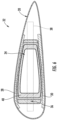
- the rotor blade 20 may also include a joint assembly 32 formed by a longitudinally extending (e.g. span-wise) rigid male structural member 34 that extends through a female structural member 36.
- the male structural member 34 may form part of a shear web of the rotor blade 20 as well as part of the spar caps thereof 28, 30.
- the female structural member 36 may form part of the shear web as well.
- the joint assembly 32 provides structural integrity to the rotor blade 20 (i.e. by acting as the shear web between opposing spar caps 28, 30) and joins adjacent rotor blade segments 26 together as described herein.
- the first rotor blade segment 25 includes the female structural member 36 therein.
- the female structural member 36 defines an internal passageway 45.
- the female structural member 36 has a certain keyed profile that corresponds or matches the cross-sectional profile of the male structural member 34.
- the female structural member 36 may be adhered to the inner skins of the shell components 21, 23 and spar caps 28, 30 using any suitable adhesive material or bonding method.
- the female structural member 36 may be attached directly to the inner skin surfaces of the shell components 21, 23 or may be attached to a separate web that is adhered to the inner skin surfaces for added support and rigidity.
- the male structural member 34 extends from an end face 35 the second blade segment 26 and has a particular cross-sectional profile that generally corresponds to the cross-sectional shape of the internal passageway 45 of the female structural member 36.
- the male and female structural members 34, 36 may take on various shapes and configurations.
- the male structural member 34 corresponds to a beam-like structure and a hollow box beam structure, respectively.
- the internal passageway 45 of the female structural member 36 have a generally box-like cross-sectional profile that corresponds to the profile of the male structural member 34.
- the male structural member 34 may have a hollow square or rectangular configuration, with the spar caps 28, 30 defined by opposite sides of the box beam structure.
- the male structural member 34 may have a hollow beam structure with concave or convex walls extending between the spar caps 28, 30.
- the male and female structural members 34, 36 may be formed of any suitable material conventionally used as internal shear webs for wind turbine blades.
- the male and/or female structural members 34, 36 may be formed of a carbon fiber reinforced matrix or a glass fiber reinforced polymer, or other strong, light-weight material.
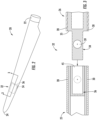
- the female structural member 36 may also include first bore holes 37 on opposing sides thereof. More specifically, as shown, the first bore holes 37 may be aligned in a chord-wise direction. Similarly, as shown in FIGS. 3 , 5 and 6 , the male structural member 34 includes second bore holes 39 on opposing sides thereof that are aligned with the first bore holes 37.
- the joint assembly 32 includes at least chord-wise extending pin 38 extending through the first and second bore holes 37, 39 so as to join the first and second rotor blade segments 25, 26 together at a joint 33.
- the rotor blade 20 may also include at least one span-wise extending pin 48 extending through either or both of the male and female structural members 34, 36 so as to secure the plurality of rotor blade segments 26 to the root ring 35 of the rotor blade 20. More specifically, as shown, each joint 33 may further include at least one bushing 41 for receiving the span-wise extending pin(s) 48 and the chord-wise extending pin(s) 38.
- FIGS. 7 and 9 cross-sectional views of a segmented rotor blade according to conventional construction and according to the present disclosure are illustrated, respectively.
- the male structural member 34 has a constant height from the blade root 22 to the chord-wise extending pin 38.
- the deflected shape of the male structural member 34 contacts the female structural member 36 between the pins 38, 48, which decrease the clearance at the edges of the bushings 41 for the pins 38, 48.
- the male structural member 34 has a height 43 that increases from the blade root 22 of the rotor blade 20 towards the chord-wise extending pin 38. More specifically, as shown, the height 43 of the male structural member 34 increases to a maximum height at the chord-wise extending pin(s) 38. In such embodiments, as shown, the maximum height of the male structural member 34 closes the gap 40 at the chord-wise extending pin 38. Still referring to FIG. 8 , the height 43 of the male structural member 34 of the present disclosure may also decrease from the maximum height at the chord-wise extending pin 38 towards the blade tip 24 of the rotor blade 20.
- the male structural member 34 can contact the female structural member 36 only at the locations of the pins 38, 48.
- the male structural member 34 can be sized such that its deflected profile ( FIG. 10 ) within the female structural member 36 is small enough that the members 34, 36 do not make contact outside of the pins constraining the members 34, 36 together. Due to the arrangement, however, there is no difference in deflection at the pins 38, 48 between the female structural member 36 and the male structural member 34. This allows the height 43 of the male structural member 34 to increase locally at least at the chord-wise extending pin 38, thereby creating more head-room for the pin 38 to occupy space.
- the present disclosure provides many advantages not present in the prior art.
- the joint assembly 32 of the present disclosure provides increased space for the chord-wise extending pin(s) 38.
- the male structural member 34 is more efficient for the same amount of material.
- the joint assembly 32 of the present disclosure allows for longer blade tips.
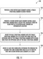
- the method 100 includes providing a first rotor blade segment 25 having a female structural member 36 secured therein.
- the method includes providing a second rotor blade segment 26 having a male structural member 34 having a height 43 that increases from the blade root 22 of the rotor blade 20 towards an intermediate location 31.
- the method 100 includes inserting the male structural member 34 into the female structural member 36 so as to align the first bore holes 37 on opposing sides of the female structural member 36 with second bore holes 39 on opposing sides of the male structural member 36.
- the method 100 include inserting at least one chord-wise extending pin 38 through the aligned first and second bore holes 37, 39 so as to join the first and second rotor blade segments 25, 26 at a joint 33.
- the method 100 also includes aligning the intermediate location 31 of the male structural member 34 with the joint 33.
- the intermediate location 31 corresponds to maximum height of the male structural member 34.
Landscapes
- Engineering & Computer Science (AREA)
- Life Sciences & Earth Sciences (AREA)
- Sustainable Development (AREA)
- Sustainable Energy (AREA)
- Chemical & Material Sciences (AREA)
- Combustion & Propulsion (AREA)
- Mechanical Engineering (AREA)
- General Engineering & Computer Science (AREA)
- Wind Motors (AREA)
Claims (11)
- Segmentiertes Rotorblatt (20) für eine Windkraftanlage (10), umfassend:ein erstes Rotorblattsegment (25), umfassend ein Aufnahmestrukturelement (36), wobei das Aufnahmestrukturelement (36) erste Bohrungen (37) auf gegenüberliegenden Seiten davon umfasst, wobei die ersten Bohrungen (37) in einer Sehnenrichtung aufeinander ausgerichtet sind;ein zweites Rotorblattsegment (26), umfassend ein davon vorstehendes Steckstrukturelement (34), wobei das Steckstrukturelement (34) eine balkenartige Struktur umfasst, die sich in Längsrichtung durch das Aufnahmestrukturelement (36) erstreckt, sodass das erste und das zweite Rotorblattsegment (25, 26) aufeinander ausgerichtet und gekoppelt sind, wobei die balkenartige Struktur des Steckstrukturelements (34) zweite Bohrungen (39) auf gegenüberliegenden Seiten davon umfasst, wobei die zweiten Bohrungen (39) auf die ersten Bohrungen (37) ausgerichtet sind; undmindestens einen sich in Sehnenrichtung erstreckenden Zapfen (38), der sich durch die ersten und die zweiten Bohrungen (37, 39) erstreckt, um das erste und das zweite Rotorblattsegment (25, 26) miteinander zu verbinden, dadurch gekennzeichnet, dass die balkenartige Struktur des Steckstrukturelements (34) eine Höhe (43) umfasst, die von einer Blattwurzel (22) des Rotorblatts (20) in Richtung des mindestens einen sich in Sehnenrichtung erstreckenden Zapfens (38) zunimmt.
- Rotorblatt (20) nach Anspruch 1, wobei die Höhe (43) auf eine maximale Höhe (43) an dem mindestens einen sich in Sehnenrichtung erstreckenden Zapfen (38) zunimmt.
- Rotorblatt (20) nach Anspruch 2, ferner umfassend mindestens einen Spalt (40), der zwischen einer Außenseitenoberfläche (46) des Steckstrukturelements (34) und einer Innenseitenoberfläche (44) des Aufnahmestrukturelements (36) gebildet ist, wobei die maximale Höhe (43) des Steckstrukturelements (34) den Spalt (40) an dem sich in Sehnenrichtung erstreckenden Zapfen (38) schließt.
- Rotorblatt (20) nach Anspruch 2, wobei die Höhe (43) des Streckstrukturelements (34) von der maximalen Höhe (43) in Richtung einer Blattspitze (24) des Rotorblatts (20) abnimmt.
- Rotorblatt (20) nach einem der vorangehenden Ansprüche, ferner umfassend mindestens einen sich in Spannenrichtung erstreckenden Zapfen (48), der sich durch das Steckstrukturelement (34) und/oder das Aufnahmestrukturelement (36) erstreckt, um die Vielzahl von Segmenten des Rotorblatts (20) an einem Wurzelring des Rotorblatts (20) zu befestigen.
- Rotorblatt (20) nach Anspruch 5, wobei das Steckstrukturelement (34) das Aufnahmestrukturelement (36) nur an dem mindestens einen sich in Spannenrichtung erstreckenden Zapfen (48) und dem mindestens einen sich in Sehnenrichtung erstreckenden Zapfen (38) berührt.
- Rotorblatt (20) nach einem der vorangehenden Ansprüche, ferner umfassend mindestens eine Buchse (41) zum jeweiligen Aufnehmen des mindestens einen sich in Spannenrichtung erstreckenden Zapfens (48) und des mindestens einen sich in Sehnenrichtung erstreckenden Zapfens (38).
- Verfahren zum Verbinden einer Vielzahl von Segmenten eines Rotorblatts (20), wobei das Verfahren Folgendes umfasst:Bereitstellen eines ersten Segments (25) des Rotorblatts (20), in dem ein Aufnahmestrukturelement (36) befestigt ist;Bereitstellen eines zweiten Segments (26) des Rotorblatts, von dem sich ein eine balkenartige Struktur umfassendes Steckstrukturelement (34) erstreckt, wobei die balkenartige Struktur des Steckstrukturelements (34) eine Höhe (43) aufweist, die von einer Flügelwurzel (22) des Rotorblatts (20) in Richtung einer Zwischenstelle (31) zunimmt;Einstecken des Steckstrukturelements (34) in das Aufnahmestrukturelement (36), um erste Bohrungen (37) auf gegenüberliegenden Seiten des Aufnahmestrukturelements (36) auf zweite Bohrungen (39) auf gegenüberliegenden Seiten der balkenartigen Struktur des Steckstrukturelements (34) auszurichten; undStecken des mindestens einen sich in Sehnenrichtung erstreckenden Zapfens (38) durch die aufeinander ausgerichteten ersten und zweiten Bohrungen (39), um das erste und das zweite Rotorblattsegment (25, 26) an einer Verbindungsstelle (33) zu verbinden.
- Verfahren nach Anspruch 8, ferner umfassend das Ausrichten der Zwischenstelle (31) des Steckstrukturelements (34) auf die Verbindungsstelle (33), wobei die Zwischenstelle (31) der maximalen Höhe (43) des Steckstrukturelements (34) entspricht.
- Verfahren nach Anspruch 9, wobei mindestens ein Spalt (40) zwischen einer Außenseitenoberfläche (46) des Steckstrukturelements (34) und einer Innenseitenoberfläche (44) des Aufnahmestrukturelements (36) definiert ist, wobei die maximale Höhe (43) des Steckstrukturelements (34) den Spalt (40) an der Verbindungsstelle (33) schließt.
- Verfahren nach Anspruch 10, wobei die Höhe (43) des Streckstrukturelements (34) von der maximalen Höhe (43) in Richtung einer Blattspitze (24) des Rotorblatts (20) abnimmt.
Applications Claiming Priority (2)
| Application Number | Priority Date | Filing Date | Title |
|---|---|---|---|
| US15/670,102 US10563636B2 (en) | 2017-08-07 | 2017-08-07 | Joint assembly for a wind turbine rotor blade |
| PCT/US2018/045476 WO2019032487A1 (en) | 2017-08-07 | 2018-08-07 | JOINT ASSEMBLY FOR A WIND ROTOR BLADE |
Publications (3)
| Publication Number | Publication Date |
|---|---|
| EP3665385A1 EP3665385A1 (de) | 2020-06-17 |
| EP3665385A4 EP3665385A4 (de) | 2021-05-19 |
| EP3665385B1 true EP3665385B1 (de) | 2025-04-02 |
Family
ID=65230983
Family Applications (1)
| Application Number | Title | Priority Date | Filing Date |
|---|---|---|---|
| EP18845276.7A Active EP3665385B1 (de) | 2017-08-07 | 2018-08-07 | Gelenkanordnung für eine windturbinenrotorschaufel |
Country Status (9)
| Country | Link |
|---|---|
| US (1) | US10563636B2 (de) |
| EP (1) | EP3665385B1 (de) |
| CN (1) | CN111051693A (de) |
| CA (1) | CA3072202A1 (de) |
| DK (1) | DK3665385T3 (de) |
| ES (1) | ES3033313T3 (de) |
| MX (1) | MX2020001503A (de) |
| PL (1) | PL3665385T3 (de) |
| WO (1) | WO2019032487A1 (de) |
Families Citing this family (5)
| Publication number | Priority date | Publication date | Assignee | Title |
|---|---|---|---|---|
| US10830207B2 (en) * | 2018-08-28 | 2020-11-10 | General Electric Company | Spar configuration for jointed wind turbine rotor blades |
| US10794359B2 (en) * | 2018-09-24 | 2020-10-06 | General Electric Company | Jointed wind turbine blade with noise reduction tape |
| CN112888852A (zh) * | 2018-10-25 | 2021-06-01 | Lm风力发电公司 | 用于风力涡轮机叶片的雷电防护 |
| WO2020091791A1 (en) * | 2018-11-01 | 2020-05-07 | General Electric Company | Spacer material for reducing a bond gap between a beam structure and a blade shell of a segmented rotor blade |
| US11353002B2 (en) | 2019-01-16 | 2022-06-07 | Roller Bearing Company Of America, Inc. | Multi segment wind turbine blade joint bushing |
Citations (1)
| Publication number | Priority date | Publication date | Assignee | Title |
|---|---|---|---|---|
| EP2957765B1 (de) * | 2014-06-19 | 2017-08-09 | General Electric Company | Windturbinenschaufelspitzengelenk |
Family Cites Families (107)
| Publication number | Priority date | Publication date | Assignee | Title |
|---|---|---|---|---|
| US2503450A (en) | 1945-03-05 | 1950-04-11 | Universal Moulded Products Cor | Airfoil |
| US2456007A (en) | 1945-08-24 | 1948-12-14 | Newman M Marsllius | Index head |
| US3013614A (en) | 1956-03-14 | 1961-12-19 | Haviland H Platt | Rotor blade |
| US2981337A (en) | 1959-09-08 | 1961-04-25 | Hiller Aircraft Corp | Propeller blade |
| US3779487A (en) | 1971-04-19 | 1973-12-18 | L Ashton | Light weight contoured load carrying structure |
| US3771748A (en) | 1972-10-10 | 1973-11-13 | I M Ind Kynock Ltd | Structures |
| US4130380A (en) | 1976-05-13 | 1978-12-19 | Kaiser Heinz W | Wind powered turbine and airfoil construction |
| DE3113079C2 (de) | 1981-04-01 | 1985-11-21 | Messerschmitt-Bölkow-Blohm GmbH, 8000 München | Aerodynamischer Groß-Flügel und Verfahren zu dessen Herstellung |
| US4671470A (en) | 1985-07-15 | 1987-06-09 | Beech Aircraft Corporation | Method for fastening aircraft frame elements to sandwich skin panels covering same using woven fiber connectors |
| FR2624913B1 (fr) | 1987-12-16 | 1990-04-20 | Snecma | Dispositif de fixation a vis d'une piece de revolution sur une bride annulaire de turbomachine |
| US4895491A (en) | 1988-06-17 | 1990-01-23 | Environmental Elements Corp. | Fan blade protection system |
| US5127802A (en) | 1990-12-24 | 1992-07-07 | United Technologies Corporation | Reinforced full-spar composite rotor blade |
| AT398064B (de) | 1992-07-01 | 1994-09-26 | Hoac Austria Flugzeugwerk Wr N | Kunststoff-verbundprofil, insbesondere flügelholm für den flugzeugbau |
| JP2000043796A (ja) | 1998-07-30 | 2000-02-15 | Japan Aircraft Development Corp | 複合材の翼形構造およびその成形方法 |
| US6513757B1 (en) | 1999-07-19 | 2003-02-04 | Fuji Jukogyo Kabushiki Kaisha | Wing of composite material and method of fabricating the same |
| US6287079B1 (en) | 1999-12-03 | 2001-09-11 | Siemens Westinghouse Power Corporation | Shear pin with locking cam |
| DE19962454A1 (de) | 1999-12-22 | 2001-07-05 | Aerodyn Eng Gmbh | Rotorblatt für Windenergieanlagen |
| DE19962989B4 (de) | 1999-12-24 | 2006-04-13 | Wobben, Aloys, Dipl.-Ing. | Rotorblatt für Windenergieanlagen |
| US6520706B1 (en) | 2000-08-25 | 2003-02-18 | Lockheed Martin Corporation | Composite material support structures with sinusoidal webs and method of fabricating same |
| US6863767B2 (en) | 2001-08-23 | 2005-03-08 | Lockheed Martin Corporation | Paste-bond clevis joint |
| US6800956B2 (en) | 2002-01-30 | 2004-10-05 | Lexington Bartlett | Wind power system |
| DK175718B1 (da) | 2002-04-15 | 2005-02-07 | Ssp Technology As | Möllevinge |
| US6945727B2 (en) | 2002-07-19 | 2005-09-20 | The Boeing Company | Apparatuses and methods for joining structural members, such as composite structural members |
| DE10235496B4 (de) | 2002-08-02 | 2015-07-30 | General Electric Co. | Verfahren zum Herstellen eines Rotorblattes, Rotorblatt und Windenergieanlage |
| US6964723B2 (en) | 2002-10-04 | 2005-11-15 | The Boeing Company | Method for applying pressure to composite laminate areas masked by secondary features |
| WO2004076852A2 (en) | 2003-02-28 | 2004-09-10 | Vestas Wind Systems A/S | Method of manufacturing a wind turbine blade, wind turbine blade, front cover and use of a front cover |
| US7244487B2 (en) | 2003-04-24 | 2007-07-17 | Lockheed Martin Corporation | Apparatus, system, and method of joining structural components with a tapered tension bond joint |
| DE10324166B4 (de) | 2003-05-28 | 2005-05-04 | Aloys Wobben | Rotorblattanschluss |
| US7037568B1 (en) | 2003-07-15 | 2006-05-02 | Rogers Terry W | Joining member for mechanically joining a skin to a supporting rib |
| FR2864175B1 (fr) | 2003-12-22 | 2008-03-28 | Airbus | Eolienne |
| JP4580169B2 (ja) | 2004-02-05 | 2010-11-10 | 富士重工業株式会社 | 風車用分割型ブレード及び風車の耐雷装置 |
| EP1584817A1 (de) | 2004-04-07 | 2005-10-12 | Gamesa Eolica, S.A. (Sociedad Unipersonal) | Windturbinenblatt |
| ATE534817T1 (de) | 2004-06-30 | 2011-12-15 | Vestas Wind Sys As | Aus zwei getrennten teilen hergestellte windturbinenflügel |
| GB0415545D0 (en) | 2004-07-12 | 2004-08-11 | Peace Steven | Wind turbine |
| US7258828B2 (en) | 2004-09-03 | 2007-08-21 | Lockheed Martin Corporation | Infusion joining of composite structures |
| ES2249182B1 (es) | 2004-09-14 | 2007-05-01 | Gamesa Eolica S.A. | Viga estructural de la pala de un aerogenerador eolico y proceso de fabricacion de la misma. |
| US7381029B2 (en) | 2004-09-30 | 2008-06-03 | General Electric Company | Multi-piece wind turbine rotor blades and wind turbines incorporating same |
| ES2255454B1 (es) | 2004-12-15 | 2007-07-01 | Gamesa Eolica, S.A. | Sistema pararrayos para pala de aerogenerador. |
| JP4691565B2 (ja) | 2004-12-29 | 2011-06-01 | ヴェスタス ウィンド システムズ アー/エス | 固定部材を有する風力タービンブレードシェル部材を製造する方法および固定部材を有する風力タービンブレード |
| US20060225278A1 (en) | 2005-03-31 | 2006-10-12 | Lin Wendy W | Wind blade construction and system and method thereof |
| ES2265760B1 (es) | 2005-03-31 | 2008-01-16 | GAMESA INNOVATION & TECHNOLOGY, S.L. | Pala para generadores eolicos. |
| US7393488B2 (en) | 2005-05-25 | 2008-07-01 | The Boeing Company | Methods of joining structures and joints formed thereby |
| DE102005026010B4 (de) | 2005-06-07 | 2010-12-30 | Airbus Deutschland Gmbh | Verfahren zur Herstellung einer verstärkten Schale zur Bildung von Teilkomponenten für Luftfahrzeuge |
| DK1754886T3 (da) | 2005-08-17 | 2012-12-17 | Gen Electric | Rotorblad til en vindenergiturbine |
| US7393184B2 (en) | 2005-11-10 | 2008-07-01 | General Electric Company | Modular blades and methods for making same |
| DE102005054594A1 (de) | 2005-11-14 | 2007-05-16 | Daubner & Stommel Gbr | Rotorblatt für eine Windenergieanlage |
| US7427189B2 (en) | 2006-02-13 | 2008-09-23 | General Electric Company | Wind turbine rotor blade |
| US7654799B2 (en) | 2006-04-30 | 2010-02-02 | General Electric Company | Modular rotor blade for a wind turbine and method for assembling same |
| US7810757B2 (en) | 2006-11-02 | 2010-10-12 | The Boeing Company | Mounting device for an aircraft |
| US7753626B2 (en) | 2007-01-18 | 2010-07-13 | Kennametal Inc. | Micro-adjustable differential screw assembly |
| JP5242920B2 (ja) | 2007-01-23 | 2013-07-24 | 株式会社日立製作所 | 風車用分割翼 |
| US7976282B2 (en) | 2007-01-26 | 2011-07-12 | General Electric Company | Preform spar cap for a wind turbine rotor blade |
| US8075275B2 (en) | 2007-09-27 | 2011-12-13 | General Electric Company | Wind turbine spars with jointed shear webs |
| US8221085B2 (en) | 2007-12-13 | 2012-07-17 | General Electric Company | Wind blade joint bonding grid |
| US8171633B2 (en) | 2007-12-19 | 2012-05-08 | General Electric Company | Method for assembling a multi-segment wind turbine blade |
| US8167569B2 (en) | 2007-12-21 | 2012-05-01 | General Electric Company | Structure and method for self-aligning rotor blade joints |
| US8240962B2 (en) | 2007-12-28 | 2012-08-14 | General Electric Company | Integrated shipping fixture and assembly method for jointed wind turbine blades |
| CA2703641A1 (en) | 2008-01-14 | 2009-07-23 | Clipper Windpower, Inc. | A modular rotor blade for a power-generating turbine and a method for assembling a power-generating turbine with modular rotor blades |
| EP2110552B2 (de) | 2008-04-15 | 2018-12-26 | Siemens Aktiengesellschaft | Windturbinenschaufel mit integriertem Blitzableiter und Verfahren zu seiner Herstellung |
| GB0807515D0 (en) | 2008-04-24 | 2008-06-04 | Blade Dynamics Ltd | A wind turbine blade |
| US9765756B2 (en) | 2008-05-07 | 2017-09-19 | Vestas Wind Systems A/S | Sectional blade |
| WO2009155921A1 (en) | 2008-06-23 | 2009-12-30 | Danmarks Tekniske Universitet | A wind turbine blade with angled girders |
| WO2009155920A1 (en) | 2008-06-24 | 2009-12-30 | Danmarks Tekniske Universitet | A reinforced wind turbine blade |
| EP2334932B2 (de) | 2008-08-25 | 2024-05-01 | Vestas Wind Systems A/S | Anordnung und verfahren zur herstellung einer anordnung |
| US20110158788A1 (en) * | 2008-08-31 | 2011-06-30 | Vestas Wind Systems A/S | A sectional blade |
| JP5249684B2 (ja) | 2008-09-04 | 2013-07-31 | 三菱重工業株式会社 | 風車翼 |
| WO2010048370A1 (en) | 2008-10-22 | 2010-04-29 | Vec Industries, L.L.C. | Wind turbine blade and method for manufacturing thereof |
| US8510947B2 (en) | 2008-11-14 | 2013-08-20 | General Electric Company | Turbine blade fabrication |
| US7891947B2 (en) | 2008-12-12 | 2011-02-22 | General Electric Company | Turbine blade and method of fabricating the same |
| US8079820B2 (en) * | 2008-12-18 | 2011-12-20 | General Electric Company | Blade module, a modular rotor blade and a method for assembling a modular rotor blade |
| ES2542869T3 (es) | 2009-01-27 | 2015-08-12 | Vestas Wind Systems A/S | Pala de turbina eólica dividida en secciones |
| US7841835B2 (en) | 2009-02-20 | 2010-11-30 | General Electric Company | Spar cap for wind turbine blades |
| ES2373154B2 (es) | 2009-04-22 | 2012-06-07 | Gamesa Innovation & Technology, S.L. | Sistema de protección de rayos para palas seccionales. |
| US7854594B2 (en) * | 2009-04-28 | 2010-12-21 | General Electric Company | Segmented wind turbine blade |
| US7998303B2 (en) | 2009-05-28 | 2011-08-16 | General Electric Company | Method for assembling jointed wind turbine blade |
| DE102009031947A1 (de) | 2009-07-07 | 2011-01-13 | Nordex Energy Gmbh | Rotorblatt für eine Windenergieanlage und Verfahren zu dessen Herstellung |
| EP2357357B1 (de) | 2009-10-01 | 2016-11-09 | Vestas Wind Systems A/S | Windturbinenschaufel |
| EP2317124B1 (de) | 2009-10-01 | 2018-08-08 | Vestas Wind Systems A/S | Windturbinenschaufel |
| JP5528053B2 (ja) | 2009-10-19 | 2014-06-25 | キヤノン株式会社 | 画像形成装置 |
| DE102009046586B4 (de) | 2009-11-10 | 2012-02-23 | Nordex Energy Gmbh | Blattspitze für ein Rotorblatt einer Windenergieanlage und Verfahren zur Montage der Blattspitze an ein Rotorblatt |
| US9388789B2 (en) | 2009-12-02 | 2016-07-12 | Vestas Wind Systems A/S | Sectional wind turbine blade |
| WO2011070137A1 (en) | 2009-12-11 | 2011-06-16 | Vestas Wind Systems A/S | A sectional blade |
| EP2390498B1 (de) | 2010-05-27 | 2017-02-22 | Siemens Aktiengesellschaft | Windturbinenschaufel mit Beschichtung zum Blitzschutz und Verfahren zur Herstellung der Windturbinenschaufel |
| EP2416005A1 (de) | 2010-08-02 | 2012-02-08 | Siemens Aktiengesellschaft | Anordnung zum Schutz vor Blitzen bei einem Windturbinenblatt |
| US7997874B2 (en) | 2010-08-19 | 2011-08-16 | General Electric Company | Wind turbine rotor blade joint |
| US7976275B2 (en) | 2010-08-30 | 2011-07-12 | General Electric Company | Wind turbine rotor blade assembly having an access window and related methods |
| DE102010040596A1 (de) | 2010-09-10 | 2012-03-15 | Aloys Wobben | Abnehmbare Rotorblattspitze |
| JP4939640B2 (ja) | 2010-10-22 | 2012-05-30 | 三菱重工業株式会社 | 風車回転翼 |
| US7922454B1 (en) * | 2010-10-29 | 2011-04-12 | General Electric Company | Joint design for rotor blade segments of a wind turbine |
| ES2396839B1 (es) | 2010-11-30 | 2014-01-02 | Gamesa Innovation & Technology, S.L. | Sistema pararrayos para pala de aerogenerador con laminados de fibra de carbono. |
| US20110243736A1 (en) | 2010-12-08 | 2011-10-06 | General Electric Company | Joint sleeve for a rotor blade assembly of a wind turbine |
| US8317483B2 (en) | 2010-12-15 | 2012-11-27 | General Electric Company | Wind turbine rotor blade |
| ES2387432B1 (es) | 2011-02-25 | 2013-07-29 | Francisco Javier Garcia Castro | Procedimiento para la fabricación de palas eólicas, palas para hélices, alas o estructuras similares y estructura en forma de pala obtenida mediante dicho procedimiento |
| US8262362B2 (en) | 2011-06-08 | 2012-09-11 | General Electric Company | Wind turbine blade shear web with spring flanges |
| US8393871B2 (en) | 2011-07-19 | 2013-03-12 | General Electric Company | Wind turbine blade shear web connection assembly |
| US8235671B2 (en) | 2011-07-19 | 2012-08-07 | General Electric Company | Wind turbine blade shear web connection assembly |
| US8257048B2 (en) | 2011-07-19 | 2012-09-04 | General Electric Company | Wind turbine blade multi-component shear web with intermediate connection assembly |
| US20120027615A1 (en) | 2011-08-15 | 2012-02-02 | General Electric Company | Rotor blade |
| US20120141287A1 (en) | 2011-08-29 | 2012-06-07 | General Electric Company | Wind turbine rotor blade joint |
| US8517689B2 (en) | 2011-10-13 | 2013-08-27 | General Electric Company | Multi-segment wind turbine rotor blade with span-wise offset joints |
| US8449259B1 (en) | 2012-05-15 | 2013-05-28 | Modular Wind Energy, Inc. | Lightning protection for wind turbine blades, and associated systems and methods |
| GB2521809A (en) | 2013-10-17 | 2015-07-08 | Vestas Wind Sys As | Improvements relating to lightning protection systems for wind turbine blades |
| US9790919B2 (en) | 2014-02-25 | 2017-10-17 | General Electric Company | Joint assembly for rotor blade segments of a wind turbine |
| EP2930350B1 (de) * | 2014-04-11 | 2018-02-14 | Siemens Aktiengesellschaft | Segmentierte Rotorschaufel mit Schraubverbindung |
| FI10797U1 (fi) | 2014-12-04 | 2015-03-10 | Wicetec Oy | Johdinliitos kuparijohtimen kytkemiseksi |
| DE102014118004B3 (de) | 2014-12-05 | 2016-03-31 | Deutsches Zentrum für Luft- und Raumfahrt e.V. | Rotorblatt für Windkraftanlagen |
| EP3144526A1 (de) * | 2015-09-16 | 2017-03-22 | Siemens Aktiengesellschaft | Verbindung für ein segmentiertes windturbinenrotorblatt |
-
2017
- 2017-08-07 US US15/670,102 patent/US10563636B2/en active Active
-
2018
- 2018-08-07 EP EP18845276.7A patent/EP3665385B1/de active Active
- 2018-08-07 CN CN201880058098.2A patent/CN111051693A/zh active Pending
- 2018-08-07 DK DK18845276.7T patent/DK3665385T3/da active
- 2018-08-07 MX MX2020001503A patent/MX2020001503A/es unknown
- 2018-08-07 CA CA3072202A patent/CA3072202A1/en active Pending
- 2018-08-07 PL PL18845276.7T patent/PL3665385T3/pl unknown
- 2018-08-07 ES ES18845276T patent/ES3033313T3/es active Active
- 2018-08-07 WO PCT/US2018/045476 patent/WO2019032487A1/en not_active Ceased
Patent Citations (1)
| Publication number | Priority date | Publication date | Assignee | Title |
|---|---|---|---|---|
| EP2957765B1 (de) * | 2014-06-19 | 2017-08-09 | General Electric Company | Windturbinenschaufelspitzengelenk |
Also Published As
| Publication number | Publication date |
|---|---|
| ES3033313T3 (en) | 2025-08-01 |
| US20190040842A1 (en) | 2019-02-07 |
| CN111051693A (zh) | 2020-04-21 |
| CA3072202A1 (en) | 2019-02-14 |
| PL3665385T3 (pl) | 2025-07-21 |
| EP3665385A1 (de) | 2020-06-17 |
| BR112020002158A2 (pt) | 2020-07-28 |
| MX2020001503A (es) | 2021-04-28 |
| EP3665385A4 (de) | 2021-05-19 |
| US10563636B2 (en) | 2020-02-18 |
| DK3665385T3 (da) | 2025-06-30 |
| WO2019032487A1 (en) | 2019-02-14 |
Similar Documents
| Publication | Publication Date | Title |
|---|---|---|
| EP3631198B1 (de) | Segmentiertes rotorblatt einer windturbine mit einer verbindungsanordnung aus geflanschten buchsen | |
| EP3112671B1 (de) | Modulares windturbinenrotorblatt | |
| US10760545B2 (en) | Joint configuration for a segmented wind turbine rotor blade | |
| EP3665385B1 (de) | Gelenkanordnung für eine windturbinenrotorschaufel | |
| CN102287321B (zh) | 风力涡轮机转子叶片接头 | |
| US7854594B2 (en) | Segmented wind turbine blade | |
| US9605651B2 (en) | Spar assembly for a wind turbine rotor blade | |
| EP3707373B1 (de) | Windturbinenrotorblattverbindungen mit schwimmenden verbindern | |
| CN112867864A (zh) | 用于接合的风力涡轮机叶片的梁帽构造 | |
| EP3894689B1 (de) | Segmentierte rotorschaufel mit maximierter gesamtvorbiegung durch eine erhöhte vorbiegung in einem schaufelspitzensegment davon | |
| EP3874142B1 (de) | Segmentiertes rotorblatt einer windturbine mit einem hohlen, sich in sehnenrichtung erstreckenden stift | |
| EP3899245B1 (de) | Windturbinenlaufschaufelschale mit variierenden fasertypen | |
| US20210396207A1 (en) | Compliant structures for jointed rotor blades | |
| EP3894691B1 (de) | Gelenkrotorschaufel mit einem über ein oder mehrere bauteile abgestützten sich in sehnenrichtung erstreckenden stift | |
| US20230374971A1 (en) | A mechanism for restraining movement of a locking pin | |
| EP3788251B1 (de) | Verbesserte verbindungsanordnung für eine segmentierte windturbinenrotorschaufel | |
| BR112020002158B1 (pt) | Pá de rotor segmentada para uma turbina eólica e método para juntar uma pluralidade de segmentos de pá de rotor |
Legal Events
| Date | Code | Title | Description |
|---|---|---|---|
| STAA | Information on the status of an ep patent application or granted ep patent |
Free format text: STATUS: THE INTERNATIONAL PUBLICATION HAS BEEN MADE |
|
| PUAI | Public reference made under article 153(3) epc to a published international application that has entered the european phase |
Free format text: ORIGINAL CODE: 0009012 |
|
| STAA | Information on the status of an ep patent application or granted ep patent |
Free format text: STATUS: REQUEST FOR EXAMINATION WAS MADE |
|
| 17P | Request for examination filed |
Effective date: 20200207 |
|
| AK | Designated contracting states |
Kind code of ref document: A1 Designated state(s): AL AT BE BG CH CY CZ DE DK EE ES FI FR GB GR HR HU IE IS IT LI LT LU LV MC MK MT NL NO PL PT RO RS SE SI SK SM TR |
|
| AX | Request for extension of the european patent |
Extension state: BA ME |
|
| DAV | Request for validation of the european patent (deleted) | ||
| DAX | Request for extension of the european patent (deleted) | ||
| A4 | Supplementary search report drawn up and despatched |
Effective date: 20210421 |
|
| RIC1 | Information provided on ipc code assigned before grant |
Ipc: F03D 1/06 20060101AFI20210415BHEP Ipc: F03D 13/10 20160101ALI20210415BHEP |
|
| P01 | Opt-out of the competence of the unified patent court (upc) registered |
Effective date: 20230522 |
|
| RAP1 | Party data changed (applicant data changed or rights of an application transferred) |
Owner name: LM WIND POWER A/S |
|
| STAA | Information on the status of an ep patent application or granted ep patent |
Free format text: STATUS: EXAMINATION IS IN PROGRESS |
|
| 17Q | First examination report despatched |
Effective date: 20240201 |
|
| GRAP | Despatch of communication of intention to grant a patent |
Free format text: ORIGINAL CODE: EPIDOSNIGR1 |
|
| STAA | Information on the status of an ep patent application or granted ep patent |
Free format text: STATUS: GRANT OF PATENT IS INTENDED |
|
| INTG | Intention to grant announced |
Effective date: 20241025 |
|
| RAP1 | Party data changed (applicant data changed or rights of an application transferred) |
Owner name: GENERAL ELECTRIC RENOVABLES ESPANA, S.L. |
|
| GRAS | Grant fee paid |
Free format text: ORIGINAL CODE: EPIDOSNIGR3 |
|
| GRAA | (expected) grant |
Free format text: ORIGINAL CODE: 0009210 |
|
| STAA | Information on the status of an ep patent application or granted ep patent |
Free format text: STATUS: THE PATENT HAS BEEN GRANTED |
|
| AK | Designated contracting states |
Kind code of ref document: B1 Designated state(s): AL AT BE BG CH CY CZ DE DK EE ES FI FR GB GR HR HU IE IS IT LI LT LU LV MC MK MT NL NO PL PT RO RS SE SI SK SM TR |
|
| REG | Reference to a national code |
Ref country code: GB Ref legal event code: FG4D |
|
| REG | Reference to a national code |
Ref country code: CH Ref legal event code: EP |
|
| REG | Reference to a national code |
Ref country code: IE Ref legal event code: FG4D |
|
| REG | Reference to a national code |
Ref country code: DE Ref legal event code: R096 Ref document number: 602018080781 Country of ref document: DE |
|
| REG | Reference to a national code |
Ref country code: DK Ref legal event code: T3 Effective date: 20250625 |
|
| REG | Reference to a national code |
Ref country code: ES Ref legal event code: FG2A Ref document number: 3033313 Country of ref document: ES Kind code of ref document: T3 Effective date: 20250801 |
|
| REG | Reference to a national code |
Ref country code: NL Ref legal event code: MP Effective date: 20250402 |
|
| PG25 | Lapsed in a contracting state [announced via postgrant information from national office to epo] |
Ref country code: NL Free format text: LAPSE BECAUSE OF FAILURE TO SUBMIT A TRANSLATION OF THE DESCRIPTION OR TO PAY THE FEE WITHIN THE PRESCRIBED TIME-LIMIT Effective date: 20250402 |
|
| REG | Reference to a national code |
Ref country code: AT Ref legal event code: MK05 Ref document number: 1781476 Country of ref document: AT Kind code of ref document: T Effective date: 20250402 |
|
| PG25 | Lapsed in a contracting state [announced via postgrant information from national office to epo] |
Ref country code: PT Free format text: LAPSE BECAUSE OF FAILURE TO SUBMIT A TRANSLATION OF THE DESCRIPTION OR TO PAY THE FEE WITHIN THE PRESCRIBED TIME-LIMIT Effective date: 20250804 Ref country code: FI Free format text: LAPSE BECAUSE OF FAILURE TO SUBMIT A TRANSLATION OF THE DESCRIPTION OR TO PAY THE FEE WITHIN THE PRESCRIBED TIME-LIMIT Effective date: 20250402 |
|
| PGFP | Annual fee paid to national office [announced via postgrant information from national office to epo] |
Ref country code: ES Payment date: 20250901 Year of fee payment: 8 |
|
| PGFP | Annual fee paid to national office [announced via postgrant information from national office to epo] |
Ref country code: DE Payment date: 20250724 Year of fee payment: 8 Ref country code: DK Payment date: 20250723 Year of fee payment: 8 |
|
| REG | Reference to a national code |
Ref country code: LT Ref legal event code: MG9D |
|
| PG25 | Lapsed in a contracting state [announced via postgrant information from national office to epo] |
Ref country code: GR Free format text: LAPSE BECAUSE OF FAILURE TO SUBMIT A TRANSLATION OF THE DESCRIPTION OR TO PAY THE FEE WITHIN THE PRESCRIBED TIME-LIMIT Effective date: 20250703 Ref country code: NO Free format text: LAPSE BECAUSE OF FAILURE TO SUBMIT A TRANSLATION OF THE DESCRIPTION OR TO PAY THE FEE WITHIN THE PRESCRIBED TIME-LIMIT Effective date: 20250702 |
|
| PGFP | Annual fee paid to national office [announced via postgrant information from national office to epo] |
Ref country code: PL Payment date: 20250724 Year of fee payment: 8 Ref country code: TR Payment date: 20250730 Year of fee payment: 8 |
|
| PG25 | Lapsed in a contracting state [announced via postgrant information from national office to epo] |
Ref country code: BG Free format text: LAPSE BECAUSE OF FAILURE TO SUBMIT A TRANSLATION OF THE DESCRIPTION OR TO PAY THE FEE WITHIN THE PRESCRIBED TIME-LIMIT Effective date: 20250402 |
|
| PGFP | Annual fee paid to national office [announced via postgrant information from national office to epo] |
Ref country code: GB Payment date: 20250724 Year of fee payment: 8 |
|
| PG25 | Lapsed in a contracting state [announced via postgrant information from national office to epo] |
Ref country code: HR Free format text: LAPSE BECAUSE OF FAILURE TO SUBMIT A TRANSLATION OF THE DESCRIPTION OR TO PAY THE FEE WITHIN THE PRESCRIBED TIME-LIMIT Effective date: 20250402 |
|
| PG25 | Lapsed in a contracting state [announced via postgrant information from national office to epo] |
Ref country code: AT Free format text: LAPSE BECAUSE OF FAILURE TO SUBMIT A TRANSLATION OF THE DESCRIPTION OR TO PAY THE FEE WITHIN THE PRESCRIBED TIME-LIMIT Effective date: 20250402 |
|
| PGFP | Annual fee paid to national office [announced via postgrant information from national office to epo] |
Ref country code: FR Payment date: 20250723 Year of fee payment: 8 |
|
| PG25 | Lapsed in a contracting state [announced via postgrant information from national office to epo] |
Ref country code: RS Free format text: LAPSE BECAUSE OF FAILURE TO SUBMIT A TRANSLATION OF THE DESCRIPTION OR TO PAY THE FEE WITHIN THE PRESCRIBED TIME-LIMIT Effective date: 20250702 |
|
| PG25 | Lapsed in a contracting state [announced via postgrant information from national office to epo] |
Ref country code: IS Free format text: LAPSE BECAUSE OF FAILURE TO SUBMIT A TRANSLATION OF THE DESCRIPTION OR TO PAY THE FEE WITHIN THE PRESCRIBED TIME-LIMIT Effective date: 20250802 |
|
| PG25 | Lapsed in a contracting state [announced via postgrant information from national office to epo] |
Ref country code: LV Free format text: LAPSE BECAUSE OF FAILURE TO SUBMIT A TRANSLATION OF THE DESCRIPTION OR TO PAY THE FEE WITHIN THE PRESCRIBED TIME-LIMIT Effective date: 20250402 |
|
| REG | Reference to a national code |
Ref country code: DE Ref legal event code: R097 Ref document number: 602018080781 Country of ref document: DE |
|
| PG25 | Lapsed in a contracting state [announced via postgrant information from national office to epo] |
Ref country code: SM Free format text: LAPSE BECAUSE OF FAILURE TO SUBMIT A TRANSLATION OF THE DESCRIPTION OR TO PAY THE FEE WITHIN THE PRESCRIBED TIME-LIMIT Effective date: 20250402 |
|
| PG25 | Lapsed in a contracting state [announced via postgrant information from national office to epo] |
Ref country code: CZ Free format text: LAPSE BECAUSE OF FAILURE TO SUBMIT A TRANSLATION OF THE DESCRIPTION OR TO PAY THE FEE WITHIN THE PRESCRIBED TIME-LIMIT Effective date: 20250402 |
|
| PG25 | Lapsed in a contracting state [announced via postgrant information from national office to epo] |
Ref country code: EE Free format text: LAPSE BECAUSE OF FAILURE TO SUBMIT A TRANSLATION OF THE DESCRIPTION OR TO PAY THE FEE WITHIN THE PRESCRIBED TIME-LIMIT Effective date: 20250402 |
|
| PG25 | Lapsed in a contracting state [announced via postgrant information from national office to epo] |
Ref country code: SK Free format text: LAPSE BECAUSE OF FAILURE TO SUBMIT A TRANSLATION OF THE DESCRIPTION OR TO PAY THE FEE WITHIN THE PRESCRIBED TIME-LIMIT Effective date: 20250402 Ref country code: RO Free format text: LAPSE BECAUSE OF FAILURE TO SUBMIT A TRANSLATION OF THE DESCRIPTION OR TO PAY THE FEE WITHIN THE PRESCRIBED TIME-LIMIT Effective date: 20250402 |
|
| PG25 | Lapsed in a contracting state [announced via postgrant information from national office to epo] |
Ref country code: IT Free format text: LAPSE BECAUSE OF FAILURE TO SUBMIT A TRANSLATION OF THE DESCRIPTION OR TO PAY THE FEE WITHIN THE PRESCRIBED TIME-LIMIT Effective date: 20250402 |
|
| PLBE | No opposition filed within time limit |
Free format text: ORIGINAL CODE: 0009261 |
|
| STAA | Information on the status of an ep patent application or granted ep patent |
Free format text: STATUS: NO OPPOSITION FILED WITHIN TIME LIMIT |
|
| REG | Reference to a national code |
Ref country code: CH Ref legal event code: L10 Free format text: ST27 STATUS EVENT CODE: U-0-0-L10-L00 (AS PROVIDED BY THE NATIONAL OFFICE) Effective date: 20260211 |
|
| 26N | No opposition filed |
Effective date: 20260105 |
|
| REG | Reference to a national code |
Ref country code: CH Ref legal event code: H13 Free format text: ST27 STATUS EVENT CODE: U-0-0-H10-H13 (AS PROVIDED BY THE NATIONAL OFFICE) Effective date: 20260324 |
|
| PG25 | Lapsed in a contracting state [announced via postgrant information from national office to epo] |
Ref country code: MC Free format text: LAPSE BECAUSE OF FAILURE TO SUBMIT A TRANSLATION OF THE DESCRIPTION OR TO PAY THE FEE WITHIN THE PRESCRIBED TIME-LIMIT Effective date: 20250402 |
|
| PG25 | Lapsed in a contracting state [announced via postgrant information from national office to epo] |
Ref country code: LU Free format text: LAPSE BECAUSE OF NON-PAYMENT OF DUE FEES Effective date: 20250807 |
|
| PG25 | Lapsed in a contracting state [announced via postgrant information from national office to epo] |
Ref country code: CH Free format text: LAPSE BECAUSE OF NON-PAYMENT OF DUE FEES Effective date: 20250831 |