EP3665371B1 - Abgasnachbehandlungssystem und verfahren zur abgasnachbehandlung eines verbrennungsmotors - Google Patents
Abgasnachbehandlungssystem und verfahren zur abgasnachbehandlung eines verbrennungsmotors Download PDFInfo
- Publication number
- EP3665371B1 EP3665371B1 EP18755172.6A EP18755172A EP3665371B1 EP 3665371 B1 EP3665371 B1 EP 3665371B1 EP 18755172 A EP18755172 A EP 18755172A EP 3665371 B1 EP3665371 B1 EP 3665371B1
- Authority
- EP
- European Patent Office
- Prior art keywords
- exhaust gas
- catalytic converter
- way catalytic
- internal combustion
- combustion engine
- Prior art date
- Legal status (The legal status is an assumption and is not a legal conclusion. Google has not performed a legal analysis and makes no representation as to the accuracy of the status listed.)
- Active
Links
- 238000002485 combustion reaction Methods 0.000 title claims description 82
- 238000000034 method Methods 0.000 title claims description 15
- 238000000746 purification Methods 0.000 title claims 10
- 239000007789 gas Substances 0.000 claims description 149
- 230000003197 catalytic effect Effects 0.000 claims description 115
- 239000002245 particle Substances 0.000 claims description 98
- 238000011144 upstream manufacturing Methods 0.000 claims description 31
- 238000010438 heat treatment Methods 0.000 claims description 18
- QVGXLLKOCUKJST-UHFFFAOYSA-N atomic oxygen Chemical compound [O] QVGXLLKOCUKJST-UHFFFAOYSA-N 0.000 claims description 14
- 239000001301 oxygen Substances 0.000 claims description 14
- 229910052760 oxygen Inorganic materials 0.000 claims description 14
- 239000011248 coating agent Substances 0.000 claims description 12
- 238000000576 coating method Methods 0.000 claims description 12
- 239000000446 fuel Substances 0.000 claims description 11
- 238000006243 chemical reaction Methods 0.000 claims description 6
- 239000000523 sample Substances 0.000 description 27
- 230000008929 regeneration Effects 0.000 description 16
- 238000011069 regeneration method Methods 0.000 description 16
- MWUXSHHQAYIFBG-UHFFFAOYSA-N nitrogen oxide Inorganic materials O=[N] MWUXSHHQAYIFBG-UHFFFAOYSA-N 0.000 description 12
- 239000004071 soot Substances 0.000 description 8
- 230000032683 aging Effects 0.000 description 5
- 238000003745 diagnosis Methods 0.000 description 5
- 239000003054 catalyst Substances 0.000 description 4
- 239000003344 environmental pollutant Substances 0.000 description 4
- 231100000719 pollutant Toxicity 0.000 description 4
- 230000001105 regulatory effect Effects 0.000 description 3
- 230000000717 retained effect Effects 0.000 description 3
- 238000009530 blood pressure measurement Methods 0.000 description 2
- 238000010531 catalytic reduction reaction Methods 0.000 description 2
- 229930195733 hydrocarbon Natural products 0.000 description 2
- 150000002430 hydrocarbons Chemical class 0.000 description 2
- 230000003647 oxidation Effects 0.000 description 2
- 238000007254 oxidation reaction Methods 0.000 description 2
- 239000004215 Carbon black (E152) Substances 0.000 description 1
- 230000009286 beneficial effect Effects 0.000 description 1
- 238000007664 blowing Methods 0.000 description 1
- 230000001276 controlling effect Effects 0.000 description 1
- 230000006735 deficit Effects 0.000 description 1
- 230000001419 dependent effect Effects 0.000 description 1
- 238000011161 development Methods 0.000 description 1
- 230000018109 developmental process Effects 0.000 description 1
- 238000010586 diagram Methods 0.000 description 1
- 238000002347 injection Methods 0.000 description 1
- 239000007924 injection Substances 0.000 description 1
- 238000009434 installation Methods 0.000 description 1
- 239000000203 mixture Substances 0.000 description 1
- 239000000126 substance Substances 0.000 description 1
- 238000003878 thermal aging Methods 0.000 description 1
- 239000002918 waste heat Substances 0.000 description 1
Images

Classifications
-
- F—MECHANICAL ENGINEERING; LIGHTING; HEATING; WEAPONS; BLASTING
- F01—MACHINES OR ENGINES IN GENERAL; ENGINE PLANTS IN GENERAL; STEAM ENGINES
- F01N—GAS-FLOW SILENCERS OR EXHAUST APPARATUS FOR MACHINES OR ENGINES IN GENERAL; GAS-FLOW SILENCERS OR EXHAUST APPARATUS FOR INTERNAL COMBUSTION ENGINES
- F01N3/00—Exhaust or silencing apparatus having means for purifying, rendering innocuous, or otherwise treating exhaust
- F01N3/08—Exhaust or silencing apparatus having means for purifying, rendering innocuous, or otherwise treating exhaust for rendering innocuous
- F01N3/10—Exhaust or silencing apparatus having means for purifying, rendering innocuous, or otherwise treating exhaust for rendering innocuous by thermal or catalytic conversion of noxious components of exhaust
- F01N3/101—Three-way catalysts
-
- B—PERFORMING OPERATIONS; TRANSPORTING
- B01—PHYSICAL OR CHEMICAL PROCESSES OR APPARATUS IN GENERAL
- B01D—SEPARATION
- B01D46/00—Filters or filtering processes specially modified for separating dispersed particles from gases or vapours
- B01D46/0027—Filters or filtering processes specially modified for separating dispersed particles from gases or vapours with additional separating or treating functions
-
- B—PERFORMING OPERATIONS; TRANSPORTING
- B01—PHYSICAL OR CHEMICAL PROCESSES OR APPARATUS IN GENERAL
- B01D—SEPARATION
- B01D46/00—Filters or filtering processes specially modified for separating dispersed particles from gases or vapours
- B01D46/66—Regeneration of the filtering material or filter elements inside the filter
- B01D46/80—Chemical processes for the removal of the retained particles, e.g. by burning
- B01D46/84—Chemical processes for the removal of the retained particles, e.g. by burning by heating only
-
- B—PERFORMING OPERATIONS; TRANSPORTING
- B01—PHYSICAL OR CHEMICAL PROCESSES OR APPARATUS IN GENERAL
- B01D—SEPARATION
- B01D53/00—Separation of gases or vapours; Recovering vapours of volatile solvents from gases; Chemical or biological purification of waste gases, e.g. engine exhaust gases, smoke, fumes, flue gases, aerosols
- B01D53/34—Chemical or biological purification of waste gases
- B01D53/92—Chemical or biological purification of waste gases of engine exhaust gases
- B01D53/94—Chemical or biological purification of waste gases of engine exhaust gases by catalytic processes
- B01D53/9445—Simultaneously removing carbon monoxide, hydrocarbons or nitrogen oxides making use of three-way catalysts [TWC] or four-way-catalysts [FWC]
- B01D53/9454—Simultaneously removing carbon monoxide, hydrocarbons or nitrogen oxides making use of three-way catalysts [TWC] or four-way-catalysts [FWC] characterised by a specific device
-
- F—MECHANICAL ENGINEERING; LIGHTING; HEATING; WEAPONS; BLASTING
- F01—MACHINES OR ENGINES IN GENERAL; ENGINE PLANTS IN GENERAL; STEAM ENGINES
- F01N—GAS-FLOW SILENCERS OR EXHAUST APPARATUS FOR MACHINES OR ENGINES IN GENERAL; GAS-FLOW SILENCERS OR EXHAUST APPARATUS FOR INTERNAL COMBUSTION ENGINES
- F01N11/00—Monitoring or diagnostic devices for exhaust-gas treatment apparatus, e.g. for catalytic activity
- F01N11/007—Monitoring or diagnostic devices for exhaust-gas treatment apparatus, e.g. for catalytic activity the diagnostic devices measuring oxygen or air concentration downstream of the exhaust apparatus
-
- F—MECHANICAL ENGINEERING; LIGHTING; HEATING; WEAPONS; BLASTING
- F01—MACHINES OR ENGINES IN GENERAL; ENGINE PLANTS IN GENERAL; STEAM ENGINES
- F01N—GAS-FLOW SILENCERS OR EXHAUST APPARATUS FOR MACHINES OR ENGINES IN GENERAL; GAS-FLOW SILENCERS OR EXHAUST APPARATUS FOR INTERNAL COMBUSTION ENGINES
- F01N13/00—Exhaust or silencing apparatus characterised by constructional features ; Exhaust or silencing apparatus, or parts thereof, having pertinent characteristics not provided for in, or of interest apart from, groups F01N1/00 - F01N5/00, F01N9/00, F01N11/00
- F01N13/009—Exhaust or silencing apparatus characterised by constructional features ; Exhaust or silencing apparatus, or parts thereof, having pertinent characteristics not provided for in, or of interest apart from, groups F01N1/00 - F01N5/00, F01N9/00, F01N11/00 having two or more separate purifying devices arranged in series
- F01N13/0093—Exhaust or silencing apparatus characterised by constructional features ; Exhaust or silencing apparatus, or parts thereof, having pertinent characteristics not provided for in, or of interest apart from, groups F01N1/00 - F01N5/00, F01N9/00, F01N11/00 having two or more separate purifying devices arranged in series the purifying devices are of the same type
-
- F—MECHANICAL ENGINEERING; LIGHTING; HEATING; WEAPONS; BLASTING
- F01—MACHINES OR ENGINES IN GENERAL; ENGINE PLANTS IN GENERAL; STEAM ENGINES
- F01N—GAS-FLOW SILENCERS OR EXHAUST APPARATUS FOR MACHINES OR ENGINES IN GENERAL; GAS-FLOW SILENCERS OR EXHAUST APPARATUS FOR INTERNAL COMBUSTION ENGINES
- F01N3/00—Exhaust or silencing apparatus having means for purifying, rendering innocuous, or otherwise treating exhaust
- F01N3/02—Exhaust or silencing apparatus having means for purifying, rendering innocuous, or otherwise treating exhaust for cooling, or for removing solid constituents of, exhaust
- F01N3/021—Exhaust or silencing apparatus having means for purifying, rendering innocuous, or otherwise treating exhaust for cooling, or for removing solid constituents of, exhaust by means of filters
- F01N3/023—Exhaust or silencing apparatus having means for purifying, rendering innocuous, or otherwise treating exhaust for cooling, or for removing solid constituents of, exhaust by means of filters using means for regenerating the filters, e.g. by burning trapped particles
- F01N3/025—Exhaust or silencing apparatus having means for purifying, rendering innocuous, or otherwise treating exhaust for cooling, or for removing solid constituents of, exhaust by means of filters using means for regenerating the filters, e.g. by burning trapped particles using fuel burner or by adding fuel to exhaust
-
- F—MECHANICAL ENGINEERING; LIGHTING; HEATING; WEAPONS; BLASTING
- F01—MACHINES OR ENGINES IN GENERAL; ENGINE PLANTS IN GENERAL; STEAM ENGINES
- F01N—GAS-FLOW SILENCERS OR EXHAUST APPARATUS FOR MACHINES OR ENGINES IN GENERAL; GAS-FLOW SILENCERS OR EXHAUST APPARATUS FOR INTERNAL COMBUSTION ENGINES
- F01N3/00—Exhaust or silencing apparatus having means for purifying, rendering innocuous, or otherwise treating exhaust
- F01N3/02—Exhaust or silencing apparatus having means for purifying, rendering innocuous, or otherwise treating exhaust for cooling, or for removing solid constituents of, exhaust
- F01N3/021—Exhaust or silencing apparatus having means for purifying, rendering innocuous, or otherwise treating exhaust for cooling, or for removing solid constituents of, exhaust by means of filters
- F01N3/033—Exhaust or silencing apparatus having means for purifying, rendering innocuous, or otherwise treating exhaust for cooling, or for removing solid constituents of, exhaust by means of filters in combination with other devices
- F01N3/035—Exhaust or silencing apparatus having means for purifying, rendering innocuous, or otherwise treating exhaust for cooling, or for removing solid constituents of, exhaust by means of filters in combination with other devices with catalytic reactors, e.g. catalysed diesel particulate filters
-
- F—MECHANICAL ENGINEERING; LIGHTING; HEATING; WEAPONS; BLASTING
- F01—MACHINES OR ENGINES IN GENERAL; ENGINE PLANTS IN GENERAL; STEAM ENGINES
- F01N—GAS-FLOW SILENCERS OR EXHAUST APPARATUS FOR MACHINES OR ENGINES IN GENERAL; GAS-FLOW SILENCERS OR EXHAUST APPARATUS FOR INTERNAL COMBUSTION ENGINES
- F01N3/00—Exhaust or silencing apparatus having means for purifying, rendering innocuous, or otherwise treating exhaust
- F01N3/08—Exhaust or silencing apparatus having means for purifying, rendering innocuous, or otherwise treating exhaust for rendering innocuous
- F01N3/10—Exhaust or silencing apparatus having means for purifying, rendering innocuous, or otherwise treating exhaust for rendering innocuous by thermal or catalytic conversion of noxious components of exhaust
- F01N3/18—Exhaust or silencing apparatus having means for purifying, rendering innocuous, or otherwise treating exhaust for rendering innocuous by thermal or catalytic conversion of noxious components of exhaust characterised by methods of operation; Control
- F01N3/20—Exhaust or silencing apparatus having means for purifying, rendering innocuous, or otherwise treating exhaust for rendering innocuous by thermal or catalytic conversion of noxious components of exhaust characterised by methods of operation; Control specially adapted for catalytic conversion ; Methods of operation or control of catalytic converters
- F01N3/2006—Periodically heating or cooling catalytic reactors, e.g. at cold starting or overheating
- F01N3/2033—Periodically heating or cooling catalytic reactors, e.g. at cold starting or overheating using a fuel burner or introducing fuel into exhaust duct
-
- F—MECHANICAL ENGINEERING; LIGHTING; HEATING; WEAPONS; BLASTING
- F01—MACHINES OR ENGINES IN GENERAL; ENGINE PLANTS IN GENERAL; STEAM ENGINES
- F01N—GAS-FLOW SILENCERS OR EXHAUST APPARATUS FOR MACHINES OR ENGINES IN GENERAL; GAS-FLOW SILENCERS OR EXHAUST APPARATUS FOR INTERNAL COMBUSTION ENGINES
- F01N3/00—Exhaust or silencing apparatus having means for purifying, rendering innocuous, or otherwise treating exhaust
- F01N3/08—Exhaust or silencing apparatus having means for purifying, rendering innocuous, or otherwise treating exhaust for rendering innocuous
- F01N3/10—Exhaust or silencing apparatus having means for purifying, rendering innocuous, or otherwise treating exhaust for rendering innocuous by thermal or catalytic conversion of noxious components of exhaust
- F01N3/24—Exhaust or silencing apparatus having means for purifying, rendering innocuous, or otherwise treating exhaust for rendering innocuous by thermal or catalytic conversion of noxious components of exhaust characterised by constructional aspects of converting apparatus
- F01N3/30—Arrangements for supply of additional air
-
- F—MECHANICAL ENGINEERING; LIGHTING; HEATING; WEAPONS; BLASTING
- F01—MACHINES OR ENGINES IN GENERAL; ENGINE PLANTS IN GENERAL; STEAM ENGINES
- F01N—GAS-FLOW SILENCERS OR EXHAUST APPARATUS FOR MACHINES OR ENGINES IN GENERAL; GAS-FLOW SILENCERS OR EXHAUST APPARATUS FOR INTERNAL COMBUSTION ENGINES
- F01N3/00—Exhaust or silencing apparatus having means for purifying, rendering innocuous, or otherwise treating exhaust
- F01N3/08—Exhaust or silencing apparatus having means for purifying, rendering innocuous, or otherwise treating exhaust for rendering innocuous
- F01N3/10—Exhaust or silencing apparatus having means for purifying, rendering innocuous, or otherwise treating exhaust for rendering innocuous by thermal or catalytic conversion of noxious components of exhaust
- F01N3/24—Exhaust or silencing apparatus having means for purifying, rendering innocuous, or otherwise treating exhaust for rendering innocuous by thermal or catalytic conversion of noxious components of exhaust characterised by constructional aspects of converting apparatus
- F01N3/36—Arrangements for supply of additional fuel
-
- F—MECHANICAL ENGINEERING; LIGHTING; HEATING; WEAPONS; BLASTING
- F01—MACHINES OR ENGINES IN GENERAL; ENGINE PLANTS IN GENERAL; STEAM ENGINES
- F01N—GAS-FLOW SILENCERS OR EXHAUST APPARATUS FOR MACHINES OR ENGINES IN GENERAL; GAS-FLOW SILENCERS OR EXHAUST APPARATUS FOR INTERNAL COMBUSTION ENGINES
- F01N9/00—Electrical control of exhaust gas treating apparatus
-
- F—MECHANICAL ENGINEERING; LIGHTING; HEATING; WEAPONS; BLASTING
- F01—MACHINES OR ENGINES IN GENERAL; ENGINE PLANTS IN GENERAL; STEAM ENGINES
- F01N—GAS-FLOW SILENCERS OR EXHAUST APPARATUS FOR MACHINES OR ENGINES IN GENERAL; GAS-FLOW SILENCERS OR EXHAUST APPARATUS FOR INTERNAL COMBUSTION ENGINES
- F01N2240/00—Combination or association of two or more different exhaust treating devices, or of at least one such device with an auxiliary device, not covered by indexing codes F01N2230/00 or F01N2250/00, one of the devices being
- F01N2240/14—Combination or association of two or more different exhaust treating devices, or of at least one such device with an auxiliary device, not covered by indexing codes F01N2230/00 or F01N2250/00, one of the devices being a fuel burner
-
- F—MECHANICAL ENGINEERING; LIGHTING; HEATING; WEAPONS; BLASTING
- F01—MACHINES OR ENGINES IN GENERAL; ENGINE PLANTS IN GENERAL; STEAM ENGINES
- F01N—GAS-FLOW SILENCERS OR EXHAUST APPARATUS FOR MACHINES OR ENGINES IN GENERAL; GAS-FLOW SILENCERS OR EXHAUST APPARATUS FOR INTERNAL COMBUSTION ENGINES
- F01N2340/00—Dimensional characteristics of the exhaust system, e.g. length, diameter or volume of the apparatus; Spatial arrangements of exhaust apparatuses
- F01N2340/02—Dimensional characteristics of the exhaust system, e.g. length, diameter or volume of the apparatus; Spatial arrangements of exhaust apparatuses characterised by the distance of the apparatus to the engine, or the distance between two exhaust treating apparatuses
-
- F—MECHANICAL ENGINEERING; LIGHTING; HEATING; WEAPONS; BLASTING
- F01—MACHINES OR ENGINES IN GENERAL; ENGINE PLANTS IN GENERAL; STEAM ENGINES
- F01N—GAS-FLOW SILENCERS OR EXHAUST APPARATUS FOR MACHINES OR ENGINES IN GENERAL; GAS-FLOW SILENCERS OR EXHAUST APPARATUS FOR INTERNAL COMBUSTION ENGINES
- F01N2430/00—Influencing exhaust purification, e.g. starting of catalytic reaction, filter regeneration, or the like, by controlling engine operating characteristics
- F01N2430/06—Influencing exhaust purification, e.g. starting of catalytic reaction, filter regeneration, or the like, by controlling engine operating characteristics by varying fuel-air ratio, e.g. by enriching fuel-air mixture
-
- F—MECHANICAL ENGINEERING; LIGHTING; HEATING; WEAPONS; BLASTING
- F01—MACHINES OR ENGINES IN GENERAL; ENGINE PLANTS IN GENERAL; STEAM ENGINES
- F01N—GAS-FLOW SILENCERS OR EXHAUST APPARATUS FOR MACHINES OR ENGINES IN GENERAL; GAS-FLOW SILENCERS OR EXHAUST APPARATUS FOR INTERNAL COMBUSTION ENGINES
- F01N2430/00—Influencing exhaust purification, e.g. starting of catalytic reaction, filter regeneration, or the like, by controlling engine operating characteristics
- F01N2430/08—Influencing exhaust purification, e.g. starting of catalytic reaction, filter regeneration, or the like, by controlling engine operating characteristics by modifying ignition or injection timing
- F01N2430/085—Influencing exhaust purification, e.g. starting of catalytic reaction, filter regeneration, or the like, by controlling engine operating characteristics by modifying ignition or injection timing at least a part of the injection taking place during expansion or exhaust stroke
-
- F—MECHANICAL ENGINEERING; LIGHTING; HEATING; WEAPONS; BLASTING
- F01—MACHINES OR ENGINES IN GENERAL; ENGINE PLANTS IN GENERAL; STEAM ENGINES
- F01N—GAS-FLOW SILENCERS OR EXHAUST APPARATUS FOR MACHINES OR ENGINES IN GENERAL; GAS-FLOW SILENCERS OR EXHAUST APPARATUS FOR INTERNAL COMBUSTION ENGINES
- F01N2560/00—Exhaust systems with means for detecting or measuring exhaust gas components or characteristics
- F01N2560/02—Exhaust systems with means for detecting or measuring exhaust gas components or characteristics the means being an exhaust gas sensor
- F01N2560/025—Exhaust systems with means for detecting or measuring exhaust gas components or characteristics the means being an exhaust gas sensor for measuring or detecting O2, e.g. lambda sensors
-
- F—MECHANICAL ENGINEERING; LIGHTING; HEATING; WEAPONS; BLASTING
- F01—MACHINES OR ENGINES IN GENERAL; ENGINE PLANTS IN GENERAL; STEAM ENGINES
- F01N—GAS-FLOW SILENCERS OR EXHAUST APPARATUS FOR MACHINES OR ENGINES IN GENERAL; GAS-FLOW SILENCERS OR EXHAUST APPARATUS FOR INTERNAL COMBUSTION ENGINES
- F01N2560/00—Exhaust systems with means for detecting or measuring exhaust gas components or characteristics
- F01N2560/14—Exhaust systems with means for detecting or measuring exhaust gas components or characteristics having more than one sensor of one kind
-
- F—MECHANICAL ENGINEERING; LIGHTING; HEATING; WEAPONS; BLASTING
- F01—MACHINES OR ENGINES IN GENERAL; ENGINE PLANTS IN GENERAL; STEAM ENGINES
- F01N—GAS-FLOW SILENCERS OR EXHAUST APPARATUS FOR MACHINES OR ENGINES IN GENERAL; GAS-FLOW SILENCERS OR EXHAUST APPARATUS FOR INTERNAL COMBUSTION ENGINES
- F01N2610/00—Adding substances to exhaust gases
- F01N2610/03—Adding substances to exhaust gases the substance being hydrocarbons, e.g. engine fuel
-
- F—MECHANICAL ENGINEERING; LIGHTING; HEATING; WEAPONS; BLASTING
- F01—MACHINES OR ENGINES IN GENERAL; ENGINE PLANTS IN GENERAL; STEAM ENGINES
- F01N—GAS-FLOW SILENCERS OR EXHAUST APPARATUS FOR MACHINES OR ENGINES IN GENERAL; GAS-FLOW SILENCERS OR EXHAUST APPARATUS FOR INTERNAL COMBUSTION ENGINES
- F01N2900/00—Details of electrical control or of the monitoring of the exhaust gas treating apparatus
- F01N2900/06—Parameters used for exhaust control or diagnosing
- F01N2900/14—Parameters used for exhaust control or diagnosing said parameters being related to the exhaust gas
- F01N2900/1402—Exhaust gas composition
-
- F—MECHANICAL ENGINEERING; LIGHTING; HEATING; WEAPONS; BLASTING
- F01—MACHINES OR ENGINES IN GENERAL; ENGINE PLANTS IN GENERAL; STEAM ENGINES
- F01N—GAS-FLOW SILENCERS OR EXHAUST APPARATUS FOR MACHINES OR ENGINES IN GENERAL; GAS-FLOW SILENCERS OR EXHAUST APPARATUS FOR INTERNAL COMBUSTION ENGINES
- F01N3/00—Exhaust or silencing apparatus having means for purifying, rendering innocuous, or otherwise treating exhaust
- F01N3/02—Exhaust or silencing apparatus having means for purifying, rendering innocuous, or otherwise treating exhaust for cooling, or for removing solid constituents of, exhaust
- F01N3/021—Exhaust or silencing apparatus having means for purifying, rendering innocuous, or otherwise treating exhaust for cooling, or for removing solid constituents of, exhaust by means of filters
- F01N3/023—Exhaust or silencing apparatus having means for purifying, rendering innocuous, or otherwise treating exhaust for cooling, or for removing solid constituents of, exhaust by means of filters using means for regenerating the filters, e.g. by burning trapped particles
- F01N3/025—Exhaust or silencing apparatus having means for purifying, rendering innocuous, or otherwise treating exhaust for cooling, or for removing solid constituents of, exhaust by means of filters using means for regenerating the filters, e.g. by burning trapped particles using fuel burner or by adding fuel to exhaust
- F01N3/0253—Exhaust or silencing apparatus having means for purifying, rendering innocuous, or otherwise treating exhaust for cooling, or for removing solid constituents of, exhaust by means of filters using means for regenerating the filters, e.g. by burning trapped particles using fuel burner or by adding fuel to exhaust adding fuel to exhaust gases
-
- Y—GENERAL TAGGING OF NEW TECHNOLOGICAL DEVELOPMENTS; GENERAL TAGGING OF CROSS-SECTIONAL TECHNOLOGIES SPANNING OVER SEVERAL SECTIONS OF THE IPC; TECHNICAL SUBJECTS COVERED BY FORMER USPC CROSS-REFERENCE ART COLLECTIONS [XRACs] AND DIGESTS
- Y02—TECHNOLOGIES OR APPLICATIONS FOR MITIGATION OR ADAPTATION AGAINST CLIMATE CHANGE
- Y02A—TECHNOLOGIES FOR ADAPTATION TO CLIMATE CHANGE
- Y02A50/00—TECHNOLOGIES FOR ADAPTATION TO CLIMATE CHANGE in human health protection, e.g. against extreme weather
- Y02A50/20—Air quality improvement or preservation, e.g. vehicle emission control or emission reduction by using catalytic converters
-
- Y—GENERAL TAGGING OF NEW TECHNOLOGICAL DEVELOPMENTS; GENERAL TAGGING OF CROSS-SECTIONAL TECHNOLOGIES SPANNING OVER SEVERAL SECTIONS OF THE IPC; TECHNICAL SUBJECTS COVERED BY FORMER USPC CROSS-REFERENCE ART COLLECTIONS [XRACs] AND DIGESTS
- Y02—TECHNOLOGIES OR APPLICATIONS FOR MITIGATION OR ADAPTATION AGAINST CLIMATE CHANGE
- Y02T—CLIMATE CHANGE MITIGATION TECHNOLOGIES RELATED TO TRANSPORTATION
- Y02T10/00—Road transport of goods or passengers
- Y02T10/10—Internal combustion engine [ICE] based vehicles
- Y02T10/12—Improving ICE efficiencies
-
- Y—GENERAL TAGGING OF NEW TECHNOLOGICAL DEVELOPMENTS; GENERAL TAGGING OF CROSS-SECTIONAL TECHNOLOGIES SPANNING OVER SEVERAL SECTIONS OF THE IPC; TECHNICAL SUBJECTS COVERED BY FORMER USPC CROSS-REFERENCE ART COLLECTIONS [XRACs] AND DIGESTS
- Y02—TECHNOLOGIES OR APPLICATIONS FOR MITIGATION OR ADAPTATION AGAINST CLIMATE CHANGE
- Y02T—CLIMATE CHANGE MITIGATION TECHNOLOGIES RELATED TO TRANSPORTATION
- Y02T10/00—Road transport of goods or passengers
- Y02T10/10—Internal combustion engine [ICE] based vehicles
- Y02T10/40—Engine management systems
Definitions
- the invention relates to an exhaust gas aftertreatment system for an internal combustion engine and a method for exhaust gas aftertreatment of an internal combustion engine according to the preambles of the independent claims.
- a method for exhaust gas aftertreatment of an internal combustion engine in the exhaust gas duct of which a particle filter and a three-way catalytic converter are arranged.
- the particle filter is arranged as the first component of the exhaust gas aftertreatment downstream of an outlet of the internal combustion engine.
- a three-way catalytic converter is arranged downstream of the particulate filter.
- the oxygen content in the exhaust gas is increased via a lambda control of the three-way catalytic converter to regenerate the particle filter.
- the DE 10 2010 046 747 A1 discloses an exhaust gas aftertreatment system for an Otto engine and a method for exhaust gas aftertreatment.
- a particle filter is arranged downstream of a three-way catalytic converter, whereby a secondary air system can be provided to regenerate the soot particles retained in the particle filter, which blows fresh air into the exhaust system downstream of the three-way catalytic converter and upstream of the particle filter.
- an exhaust gas aftertreatment system for an internal combustion engine in which an electrically heatable three-way catalytic converter is arranged in an exhaust system and a further three-way catalytic converter is arranged downstream of the electrically heatable three-way catalytic converter. Secondary air can be introduced into the exhaust system to reduce emissions.
- the DE 10 2012 011 603 A1 discloses an internal combustion engine with an exhaust system, wherein an HC adsorber and downstream of the HC adsorber a three-way catalyst is arranged in the exhaust system, downstream of the HC adsorber and upstream of the three-way catalyst, an exhaust gas burner for introducing hot Burner gases in the exhaust duct of the internal combustion engine is provided to the three-way catalytic converter to heat up.
- an exhaust gas burner for introducing hot Burner gases in the exhaust duct of the internal combustion engine is provided to the three-way catalytic converter to heat up.
- an internal combustion engine with an exhaust system in which a three-way catalytic converter can be heated by means of an exhaust gas burner.
- a primary catalytic converter is heated up by the burner until the harmful exhaust gas components can be converted by the primary catalytic converter and a main catalytic converter connected downstream of the primary catalytic converter.
- the DE 10 2013 003 701 A1 discloses a method for controlling a regeneration of a particulate filter of an exhaust system of an externally ignited internal combustion engine, the particulate filter being followed by a catalytic converter designed at least for converting nitrogen oxides. It is provided that an air ratio of the internal combustion engine is set to a lean lambda value during a regeneration of the particle filter and a hydrocarbon is fed to the exhaust gas of the internal combustion engine upstream of the downstream catalytic converter, so that nitrogen oxides are converted in the downstream catalytic converter.
- a regeneration system for a particle filter is known. Fresh air is introduced into the exhaust system upstream of the particle filter with a secondary air pump.
- the current soot load of the particle filter is determined via a control module. If the soot load reaches a defined threshold value, the internal combustion engine is operated with a sub-stoichiometric combustion air ratio and secondary air is simultaneously blown into the exhaust system in order to heat the particle filter.
- the JP H05 33629 A discloses a method for operating a catalytic converter in the underbody position, wherein an exhaust gas burner is supplied with fuel and fresh air at a low catalytic converter temperature, a combustible mixture of fresh air and fuel being ignited by a spark plug on the exhaust gas burner and supplied to the exhaust system. If the catalytic converter reaches a temperature sufficient to convert pollutants, the fuel supply and the fresh air supply for the exhaust gas burner are switched off.
- the object of the invention is to ensure that the particle filter reaches a regeneration temperature in all driving cycles, to improve the aging behavior of the exhaust gas aftertreatment system and to overcome the disadvantages known from the prior art.
- an exhaust gas aftertreatment system for an internal combustion engine with an exhaust system which is connected to an outlet of the internal combustion engine.
- the exhaust system comprises an exhaust gas duct in which, in the flow direction of an exhaust gas from the internal combustion engine, the first emission-reducing component is a particle filter close to the engine, downstream of the particle filter, also in a position close to the engine, a first three-way catalytic converter and downstream of the first three-way catalytic converter another three-way catalytic converter are arranged. Downstream of the particle filter, a burner is provided with which hot exhaust gas is provided for heating at least one of the three-way catalytic converters in the exhaust system.
- an arrangement of the particulate filter and the first three-way catalytic converter close to the engine is an arrangement of the exhaust gas aftertreatment components with an exhaust gas run length of less than 80 cm, in particular less than 50 cm, particularly preferably less than 35 cm from an outlet of the internal combustion engine to understand.
- This enables accelerated heating of the particle filter and the first three-way catalytic converter, in particular after a cold start of the internal combustion engine.
- the position of the particle filter close to the engine means that less waste heat is lost through the walls of the exhaust gas duct, so that, compared to a particle filter in the underbody position of the internal combustion engine, it is easier to reach the oxidation temperature of soot particles retained in the particle filter at the particle filter, which is necessary for regeneration of the particle filter.
- the exhaust gas burner allows a large amount of energy to be introduced into the exhaust system, so that at least one of the three-way catalytic converters reaches its light-off temperature shortly after a cold start and thus enables the efficient conversion of pollutants.
- the particle filter is free from a coating, in particular free from a three-way catalytically active coating or a coating for the selective catalytic reduction of nitrogen oxides, and / or free of an oxygen storage, in particular free of a washcoat with oxygen storage capacity.
- a coating in particular free from a three-way catalytically active coating or a coating for the selective catalytic reduction of nitrogen oxides, and / or free of an oxygen storage, in particular free of a washcoat with oxygen storage capacity.
- an age-related change in the properties of the particle filter can be prevented, so that the particle filter has essentially the same behavior over its lifetime.
- the function of the particle filter and the heated three-way catalytic converter can be monitored by a common pair of lambda probes, the first lambda probe being arranged upstream of the particle filter and the second lambda probe being arranged downstream of the electrically heated three-way catalytic converter.
- the particle filter is arranged as the first exhaust gas aftertreatment component after the exhaust of the internal combustion engine, the particle filter is exposed to high exhaust gas temperatures, especially when the internal combustion engine is operating at full load, which otherwise lead to increased thermal aging of a catalytic coating.
- the particle filter can be designed with fewer cells, as a result of which the thermal mass of the particle filter is reduced and heating of the particle filter is promoted.
- the exhaust gas back pressure is reduced, which means that the flow losses in the exhaust system can be reduced and the efficiency of the internal combustion engine can thus be increased. With otherwise unchanged framework conditions, this can be used to increase performance or reduce consumption.
- the thermal mass of the particle filter can be reduced in this way and the exhaust gas back pressure can be reduced and the ash storage capacity can be increased compared to a coated particle filter.
- the lower thermal mass and the position of the particle filter close to the engine also make it easier to reach the regeneration temperature of the particle filter.
- the exhaust gas burner can be operated with a variable combustion air ratio.
- the exhaust gas burner can compensate for lambda fluctuations, in particular a substoichiometric lambda operation in the cold start phase of the internal combustion engine and thus ensure stoichiometric exhaust gas downstream of the inlet point for the hot burner gases of the exhaust gas burner.
- a stoichiometric exhaust gas is regulated downstream of an inlet point of the exhaust gas burner.
- a stoichiometric exhaust gas enables particularly efficient exhaust gas aftertreatment on the three-way catalytic converters located downstream of the discharge point.
- the internal combustion engine has a secondary air system for introducing secondary air into the exhaust gas duct, an inlet point of the secondary air system being arranged at the outlet of the internal combustion engine or downstream of the outlet and upstream of the particle filter. Secondary air is blown into the hot exhaust ducts of the internal combustion engine, the unburned exhaust gas components reacting exothermically with the secondary air while still in the exhaust duct and thus ensuring that the exhaust gas is heated. The time in which the first three-way catalytic converter has reached its light-off temperature can thus be further shortened.
- the secondary air system can be used to carry out a regeneration of the particle filter and to introduce the oxygen necessary for the regeneration into the exhaust gas duct upstream of the particle filter.
- the operating state of the internal combustion engine can be adjusted accordingly when the particle filter is regenerated, so that the internal combustion engine does not have to be operated with a combustion air ratio that is above stoichiometric in order to enable regeneration of the particle filter.
- an inlet point for the exhaust gases from the exhaust gas burner is formed downstream of the particle filter and upstream of the first three-way catalytic converter.
- An inlet point downstream of the particle filter and upstream of the first three-way catalytic converter close to the engine enables the three-way catalytic converter to be heated to its light-off temperature particularly quickly, since no other components have to be heated up and, in particular, the near the engine is necessary to achieve the light-off temperature of the first three-way catalytic converter.
- a first lambda probe is arranged upstream of the particle filter and a second lambda probe is arranged in the exhaust gas duct downstream of the first (close to the engine) three-way catalytic converter and upstream of the second three-way catalytic converter.
- the second lambda probe can be designed as a step lambda probe in order to reduce costs and thus to provide a qualitative statement about an excess of oxygen in the exhaust gas.
- the second lambda probe can also be used as a Broadband probe are designed to allow quantitative control of the combustion air ratio of the exhaust gas burner.
- a first pressure sensor is arranged upstream of the particle filter and a second pressure sensor is arranged downstream of the particle filter and preferably upstream of the first three-way catalytic converter.
- a pressure sensor pair can be used to carry out a differential pressure measurement across the particle filter, by means of which a loading state of the particle filter can be determined. A regeneration of the particle filter can thus be initiated on the basis of the pressure difference.
- an on-board diagnosis of the particle filter can be carried out.
- a method according to the invention can be used to heat at least one pollutant-reducing exhaust gas aftertreatment component, in particular the first three-way catalytic converter, to a light-off temperature shortly after a cold start of the internal combustion engine, which enables the harmful gaseous exhaust gas components to be efficiently converted.
- the aging resistance of the catalytic coating can be increased, since the first three-way catalytic converter does not get as hot in full-load operation of the internal combustion engine as the particle filter arranged in the first position after the outlet.
- the regeneration of the particle filter is facilitated by the arrangement close to the engine and the disadvantages of a catalytic coating on the particle filter are avoided.
- the method for exhaust gas aftertreatment in a heating phase, one of the three-way catalytic converters or the particle filter, secondary air is introduced into the exhaust-side cylinder head or into the exhaust gas duct downstream of the outlet and upstream of the particle filter in order to heat the catalytic converters or of the particle filter through an exothermic conversion of unburned To support fuel components.
- secondary air By blowing in secondary air, the heat input from the hot exhaust gases from the exhaust gas burner can be supported, as the exothermic reaction in the exhaust gas duct generates additional heat which can be used to heat the three-way catalytic converters and the particle filter.
- FIG. 1 shows a schematic representation of an internal combustion engine 10, the outlet 12 of which is connected to an exhaust system 20.
- the internal combustion engine 10 is designed as a gasoline engine which is externally ignited by means of spark plugs 16 and has a plurality of combustion chambers 14.
- the internal combustion engine 10 is preferably designed as an internal combustion engine 10 charged by means of an exhaust gas turbocharger 30, a turbine 32 of the exhaust gas turbocharger 30 downstream of the outlet 12 and upstream of the first emission-reducing exhaust gas aftertreatment component, in particular upstream of a particle filter 24, is arranged.
- the exhaust system 20 comprises an exhaust gas duct 22 in which, in the flow direction of an exhaust gas through the exhaust gas duct 22, a particle filter 24, downstream of the particle filter 24 a first three-way catalytic converter 26, and further downstream a second three-way catalytic converter 28 are arranged.
- the particle filter 24 and the first three-way catalytic converter 26 are preferably each arranged close to the engine, that is, at a distance of less than 80 cm exhaust gas run length, in particular less than 50 cm exhaust gas run length, from the outlet 12 of the internal combustion engine 10.
- the second three-way catalytic converter 28 is preferably arranged in the underbody position of a motor vehicle and thus in a position remote from the engine, that is, at a distance of more than 100 cm of the exhaust gas run length from the outlet 12 of the internal combustion engine. Downstream of the particle filter 24 and upstream of the first three-way catalytic converter 26, there is an inlet point 38 for hot exhaust gases from an exhaust gas burner 34, via which the first three-way catalytic converter 26, which is arranged downstream of the inlet point 38, is heated regardless of the operating situation of the internal combustion engine 10 can.
- Additional catalytic converters in particular a further three-way catalytic converter, a NOx storage catalytic converter or a catalytic converter for the selective catalytic reduction of nitrogen oxides can also be arranged in the exhaust system 20.
- a first lambda probe 50 is arranged in the exhaust gas duct 22 upstream of the particle filter 24, with which the oxygen content ⁇ 1 of the exhaust gas can be determined downstream of the outlet 12 and upstream of the first exhaust gas aftertreatment component, i.e. the particle filter 24.
- a second lambda probe 52 Downstream of the first three-way catalytic converter 26 and upstream of the second three-way catalytic converter 28, a second lambda probe 52 is arranged in the exhaust gas duct 22, with which the oxygen content ⁇ 2 in the exhaust gas duct 28 downstream of the first three-way catalytic converter 26 and upstream of the second three-way catalyst 28 can be determined.
- the first lambda probe 50 is preferably designed as a broadband lambda probe and is connected to a control device 36 of the internal combustion engine 10 via a first signal line 60.
- the second lambda probe 52 is preferably designed as a jump probe and is connected to the control unit 36 via a second signal line 62.
- the first lambda probe 50 and the second lambda probe 52 form a sensor arrangement with which the combustion air ratio ⁇ of the internal combustion engine 10 can be regulated.
- an on-board diagnosis of the first three-way catalytic converter 26 can take place via the sensor arrangement.
- the exhaust gas burner 34 is via a secondary air system 40 with fresh air and via the fuel system of the internal combustion engine 10 or a separate fuel pump with a Fuel can be supplied.
- the secondary air system 40 includes a secondary air pump 46 which is connected to the exhaust gas burner 34 via a secondary air line 44.
- a secondary air valve 48 is arranged in the secondary air line 44, with which the air supply to the exhaust gas burner 34 can be established and stopped.
- pressure sensors 56, 58 are provided upstream and downstream of the particle filter 24, with which a differential pressure measurement can be carried out across the particle filter 24 to determine the loading state of the particle filter 24.
- an on-board diagnosis of the particle filter 24 can take place via the pressure sensors 56, 58.
- FIG 2 a further embodiment of an internal combustion engine is shown with an exhaust gas aftertreatment system.
- the secondary air system 40 has an additional secondary air line 64 which connects the secondary air pump 46 to an inlet point 42 on an outlet-side cylinder head 18 of the internal combustion engine 10.
- a further secondary air valve 66 is arranged in the additional secondary air line 64 in order to be able to introduce the secondary air into an exhaust gas that is as hot as possible and thus to promote exothermic reactions with unburned fuel components.
- the introduction point 42 can also be formed at points upstream of the particle filter 24 so that the particle filter 24 and the three-way catalytic converters 26, 28 arranged downstream of the particle filter 24 can be supplied with secondary air.
- the exhaust gas of the internal combustion engine 10 is passed through the particle filter 24, the first three-way catalytic converter 26 close to the engine and the second three-way catalytic converter 28 in the underbody position, the soot particles contained in the exhaust gas being filtered out of the exhaust gas flow and the harmful exhaust gas components are converted into harmless exhaust gas components.
- the arrangement of the particulate filter 24 and the first three-way catalytic converter 26 close to the engine enables particularly rapid heating to a light-off temperature after a cold start in order to enable the gaseous pollutants to be efficiently converted as quickly as possible after the cold start .
- the particle filter 24 is preferably uncoated, in particular without a coating with an oxygen storage capacity.
- a diagnosis of the first three-way catalytic converter 26 via the lambda probes 50, 52 is thereby possible. Due to the arrangement of the particle filter 24 as the first component of the exhaust gas aftertreatment, the first three-way catalytic converter 26 is not thermally activated when the internal combustion engine 10 is operating at full load so heavily loaded that the aging of the catalytic coating of the first three-way catalytic converter 26 can be reduced.
- FIG 3 a further embodiment of an internal combustion engine 10 according to the invention is shown.
- the inlet point 38 for the hot exhaust gases of the exhaust gas burner 34 in this embodiment is downstream of the first three-way catalytic converter 26 and upstream of the second three-way catalytic converter 28.
- a third one Lambda probe 54 is provided downstream of the second three-way catalytic converter 28 for regulating the combustion air ratio ⁇ B of the exhaust gas burner 34.
- the second three-way catalytic converter 28 is heated by the exhaust gas burner 34 and thus reaches its light-off temperature T LO shortly after a cold start of the internal combustion engine 10.
- This exemplary embodiment is particularly useful in the case of tightly packed engine compartment configurations in which an arrangement of the exhaust gas burner 34 close to the engine is not possible or only possible with considerable additional effort for reasons of installation space.
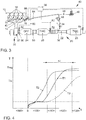
- the temperature profile is shown at several points of the exhaust system 20 when a method according to the invention for exhaust gas aftertreatment is running.
- the temperature T1 immediately downstream of the particle filter 24 is shown in a first curve I.
- the second curve II shows the temperature T2 at the first three-way catalytic converter 26 when the exhaust gas burner 34 is activated.
- the temperature T2 is determined at the center of the component of the first three-way catalytic converter 26.
- the internal combustion engine 10 is started at a starting time S and the exhaust gas burner 34 is started at the same time.
- a first phase ⁇ 100> the particle filter 24 and the first three-way catalytic converter 26 are flowed through by the exhaust gas from the internal combustion engine 10 and heated by the exhaust gas.
- the first three-way catalytic converter 26 is heated up by the hot exhaust gas from the exhaust gas burner 34, the heat from the exhaust gas burner 34 being transferred essentially convectively to the first three-way catalytic converter 26.
- T LO light-off temperature
- a third phase ⁇ 120> the exhaust gas burner 34 is switched off and the temperature of the first three-way catalytic converter 26 becomes catalytic due to the exothermic reactions of the unburned fuel components effective surface of the first three-way catalyst 26 held.
- a fourth operating phase ⁇ 130> both the first three-way catalytic converter 26 and the particle filter 24 have then reached a temperature at which no further heating measures are necessary.
- the third curve shows the temperature T3 of the first three-way catalytic converter 26 if the exhaust gas burner 34 is not activated in any of the phases ⁇ 100>, ⁇ 110> and ⁇ 120>.
- the exhaust gas burner 34 can also be activated in a pre-start phase ⁇ 90> so that the first catalytic converter 26 has already reached its light-off temperature T LO at the start S of the internal combustion engine 10 or the heating phase can be shortened again.
- an exhaust gas aftertreatment system according to the invention and the described method according to the invention can ensure that a regeneration temperature of the particle filter is reached in all driving cycles and the aging behavior of the exhaust gas aftertreatment system is reduced.
Description
- Die Erfindung betrifft ein Abgasnachbehandlungssystem für einen Verbrennungsmotor sowie ein Verfahren zur Abgasnachbehandlung eines Verbrennungsmotors gemäß den Oberbegriffen der unabhängigen Patentansprüche.
- Die kontinuierliche Verschärfung der Abgasgesetzgebung stellt hohe Anforderungen an die Fahrzeughersteller, welche durch entsprechende Maßnahmen zur Reduktion der motorischen Rohemissionen und durch eine entsprechende Abgasnachbehandlung gelöst werden. Mit Einführung der Gesetzgebungsstufe EU6 wird für Ottomotoren ein Grenzwert für eine Partikelanzahl vorgeschrieben, der in vielen Fällen den Einsatz eines Ottopartikelfilters notwendig macht. Solche Rußpartikel entstehen besonders nach einem Kaltstart des Verbrennungsmotors aufgrund einer unvollständigen Verbrennung in Kombination mit einem überstöchiometrischen Verbrennungsluftverhältnis sowie kalter Zylinderwände während des Kaltstarts. Die Kaltstartphase ist somit maßgeblich für die Einhaltung der gesetzlich vorgeschriebenen Partikelgrenzwerte. Im Fahrbetrieb wird ein solcher Ottopartikelfilter weiter mit Ruß beladen. Damit der Abgasgegendruck nicht zu stark ansteigt, muss dieser Ottopartikelfilter kontinuierlich oder periodisch regeneriert werden. Der Anstieg des Abgasgegendrucks kann zu einem Mehrverbrauch des Verbrennungsmotors, Leistungsverlust und einer Beeinträchtigung der Laufruhe bis hin zu Zündaussetzern führen. Um eine thermische Oxidation des im Ottopartikelfilter zurückgehaltenen Rußes mit Sauerstoff durchzuführen, ist ein hinreichend hohes Temperaturniveau in Verbindung mit gleichzeitig vorhandenem Sauerstoff in der Abgasanlage des Ottomotors notwendig. Da moderne Ottomotoren normalerweise ohne Sauerstoffüberschuss mit einem stöchiometrischen Verbrennungsluftverhältnis (λ=1) betrieben werden, sind dazu zusätzliche Maßnahmen erforderlich. Dazu kommen als Maßnahmen beispielsweise eine Temperaturerhöhung durch eine Zündwinkelverstellung, eine zeitweise Magerverstellung des Ottomotors, das Einblasen von Sekundärluft in die Abgasanlage oder eine Kombination dieser Maßnahmen infrage. Bevorzugt wird bislang eine Zündwinkelverstellung in Richtung spät in Kombination mit einer Magerverstellung des Ottomotors angewandt, da dieses Verfahren ohne zusätzliche Bauteile auskommt und in den meisten Betriebspunkten des Ottomotors eine ausreichende Sauerstoffmenge liefern kann.
- Aufgrund der guten Wirkungsgrade beim Ottomotor ist eine Regeneration eines Partikelfilters in Unterbodenposition in bestimmten Betriebssituationen unmöglich, sodass die Regeneration eines Partikelfilters in Unterbodenlage spezieller Fahrzyklen bedarf. Eine motornahe Positionierung des Partikelfilters ist günstig, da dadurch höhere Abgastemperaturen am Partikelfilter vorliegen und das Aufheizen auf eine Regenerationstemperatur erleichtert wird. Ein weiteres Problem bei Partikelfiltern mit einer drei-Wege-katalytisch wirksamen Beschichtung, sogenannten Vier-Wege-Katalysatoren, ist die Tatsache, dass die Beschichtung starke Alterungserscheinungen aufweisen kann, sodass für die Konvertierung der gasförmigen Schadstoffe ein zusätzlicher Drei-Wege-Katalysator in motornaher Lage erforderlich sein kann.
- Aus der
DE 10 2008 036 127 A1 ist ein Verfahren zur Abgasnachbehandlung eines Verbrennungsmotors bekannt, in dessen Abgaskanal ein Partikelfilter und ein Drei-Wege-Katalysator angeordnet sind. Dabei ist der Partikelfilter als erste Komponente der Abgasnachbehandlung stromabwärts eines Auslasses des Verbrennungsmotors angeordnet. Stromabwärts des Partikelfilters ist ein Drei-Wege-Katalysator angeordnet. Dabei wird der Sauerstoffgehalt im Abgas zur Regeneration des Partikelfilters über eine Lambdaregelung des Drei-Wege-Katalysators erhöht. - Die
DE 10 2010 046 747 A1 offenbart ein Abgasnachbehandlungssystem für einen Ottomotor sowie ein Verfahren zur Abgasnachbehandlung. Dabei ist stromabwärts eines Drei-Wege-Katalysators ein Partikelfilter angeordnet, wobei zur Regeneration der im Partikelfilter zurückgehaltenen Rußpartikel ein Sekundärluftsystem bereitgestellt werden kann, welches stromabwärts des Drei-Wege-Katalysators und stromaufwärts des Partikelfilters Frischluft in die Abgasanlage einbläst. - Aus der
DE 10 2012 204 779 A1 ist ein Abgasnachbehandlungssystem für einen Verbrennungsmotor bekannt, bei dem in einer Abgasanlage ein elektrisch beheizbarer Drei-Wege-Katalysator und stromab des elektrisch beheizbaren Drei-Wege-Katalysators ein weiterer Drei-Wege-Katalysator angeordnet sind. Dabei kann zur Emissionsminderung Sekundärluft in die Abgasanlage eingebracht werden. - Die
DE 10 2012 011 603 A1 offenbart einen Verbrennungsmotor mit einer Abgasanlage, wobei in der Abgasanlage ein HC-Adsorber und stromabwärts des HC-Adsorbers ein Drei-Wege-Katalysator angeordnet ist, wobei stromabwärts des HC-Adsorbers und stromaufwärts des Drei-Wege-Katalysators ein Abgasbrenner zur Einleitung von heißen Brennergasen in den Abgaskanal des Verbrennungsmotors vorgesehen ist, um den Drei-Wege-Katalysator aufzuheizen. Dabei können die unverbrannten Kohlenwasserstoffe bei einem Motorstart in dem HC-Adsorber zurückgehalten werden, bis der Drei-Wege-Katalysator oder ein motornaher Startkatalysator ihre Light-Off-Temperatur erreicht haben. - Ferner ist aus der
DE 10 2012 021 573 ein Verbrennungsmotor mit einer Abgasanlage bekannt, bei der ein Drei-Wege-Katalysator mittels eines Abgasbrenners aufheizbar ist. Dabei wird ein Vorkatalysator durch den Brenner aufgeheizt, bis eine Konvertierung der schädlichen Abgaskomponenten durch den Vorkatalysator und einen dem Vorkatalysator nachgeschalteten Hauptkatalysator möglich ist. - Die
DE 10 2013 003 701 A1 offenbart ein Verfahren zur Steuerung einer Regeneration eines Partikelfilters einer Abgasanlage einer fremdgezündeten Brennkraftmaschine, wobei dem Partikelfilter ein zumindest zur Konvertierung von Stickoxiden ausgebildeter Katalysator nachgeschaltet ist. Dabei ist vorgesehen, dass während einer Regeneration des Partikelfilters ein Luftverhältnis der Brennkraftmaschine auf einen mageren Lambdawert eingestellt wird und stromauf des nachgeschalteten Katalysators dem Abgas der Brennkraftmaschine ein Kohlenwasserstoff zugeführt wird, so dass in dem nachgeschalteten Katalysator eine Konvertierung von Stickoxiden erfolgt. - Aus der
US 2011 / 219 752 A1 ist ein Regenerationssystem für einen Partikelfilter bekannt. Dabei wird mit einer Sekundärluftpumpe Frischluft stromaufwärts des Partikelfilters in die Abgasanlage eingebracht. Über ein Kontrollmodul wird die aktuelle Rußbeladung des Partikelfilters ermittelt. Erreicht die Rußbeladung einen definierten Schwellenwert, so wird der Verbrennungsmotor mit einem unterstöchiometrischen Verbrennungsluftverhältnis betrieben und gleichzeitig Sekundärluft in die Abgasanlage eingeblasen, um den Partikelfilter aufzuheizen. - Die
JP H05 33629 A - Aufgabe der Erfindung ist es, in allen Fahrzyklen das Erreichen einer Regenerationstemperatur des Partikelfilters sicherzustellen, das Alterungsverhalten des Abgasnachbehandlungssystems zu verbessern und die aus dem Stand der Technik bekannten Nachteile zu überwinden.
- Erfindungsgemäß wird diese Aufgabe durch ein Abgasnachbehandlungssystem für einen Verbrennungsmotor mit einer Abgasanlage gelöst, welche mit einem Auslass des Verbrennungsmotors verbunden ist. Dabei umfasst die Abgasanlage einen Abgaskanal, in dem in Strömungsrichtung eines Abgases des Verbrennungsmotors durch den Abgaskanal als erste emissionsmindernde Komponente motornah ein Partikelfilter, stromabwärts des Partikelfilters ebenfalls in einer motornahen Position ein erster Drei-Wege-Katalysator und stromabwärts des ersten Drei-Wege-Katalysators ein weiterer Drei-Wege-Katalysator angeordnet sind. Stromabwärts des Partikelfilters ist ein Brenner vorgesehen, mit welchem heißes Abgas zur Erwärmung zumindest eines der Drei-Wege-Katalysatoren in die Abgasanlage vorgesehen ist. Unter einer motornahen Anordnung des Partikelfilters und des ersten Drei-Wege-Katalysators ist in diesem Zusammenhang eine Anordnung der Abgasnachbehandlungskomponenten mit einer Abgaslauflänge von weniger als 80 cm, insbesondere von weniger als 50 cm, besonders bevorzugt von weniger als 35 cm ab einem Auslass des Verbrennungsmotors zu verstehen. Dadurch sind eine beschleunigte Aufheizung des Partikelfilters und des ersten Drei-Wege-Katalysators, insbesondere nach einem Kaltstart des Verbrennungsmotors, möglich. Durch die motornahe Position des Partikelfilters geht weniger Abwärme über die Wände des Abgaskanals verloren, sodass es im Vergleich zu einem Partikelfilter in Unterbodenposition des Verbrennungsmotors leichter ist, am Partikelfilter eine zur Regeneration des Partikelfilters notwendige Oxidationstemperatur von im Partikelfilter zurückgehaltenen Rußpartikeln zu erreichen. Durch den Abgasbrenner kann eine hohe Energiemenge in die Abgasanlage eingebracht werden, wodurch zumindest einer der Drei-Wege-Katalysatoren zeitnah nach einem Kaltstart seine Light-Off-Temperatur erreicht und somit eine effiziente Konvertierung von Schadstoffen ermöglicht. Somit ist eine wesentlich schnellere Erwärmung des Drei-Wege-Katalysators als durch ein elektrisches Heizelement möglich, sodass der Drei-Wege-Katalysator schneller seine Light-Off-Temperatur erreicht.
- Durch die in den abhängigen Ansprüchen aufgeführten Merkmale sind vorteilhafte Verbesserungen und Weiterbildungen des erfindungsgemäßen Abgasnachbehandlungssystems für einen Verbrennungsmotor möglich.
- In bevorzugter Ausgestaltung der Erfindung ist vorgesehen, dass der Partikelfilter frei von einer Beschichtung, insbesondere frei von einer drei-Wege-katalytisch wirksamen Beschichtung oder einer Beschichtung zur selektiven katalytischen Reduktion von Stickoxiden, und/oder frei von einem Sauerstoffspeicher, insbesondere frei von einem Washcoat mit Sauerstoffspeicherfähigkeit, ausgeführt ist. Dadurch kann eine alterungsbedingte Veränderung der Eigenschaften des Partikelfilters verhindert werden, sodass der Partikelfilter über seine Lebenszeit ein im Wesentlichen gleiches Verhalten aufweist. Zudem kann auf diese Weise die Funktion des Partikelfilters und des beheizbaren Drei-Wege-Katalysators durch ein gemeinsames Lambdasondenpaar überwacht werden, wobei die erste Lambdasonde stromaufwärts des Partikelfilters und die zweite Lambdasonde stromabwärts des elektrisch beheizbaren Drei-Wege-Katalysators angeordnet ist. Da der Partikelfilter als erste Abgasnachbehandlungskomponente nach dem Auslass des Verbrennungsmotors angeordnet ist, wird der Partikelfilter insbesondere bei einem Volllastbetrieb des Verbrennungsmotors mit hohen Abgastemperaturen beaufschlagt, welche ansonsten zu einer verstärkten thermischen Alterung einer katalytischen Beschichtung führen. Zudem kann durch den Verzicht auf eine Beschichtung der Partikelfilter mit weniger Zellen ausgeführt werden, wodurch die thermische Masse des Partikelfilters reduziert wird und ein Aufheizen des Partikelfilters begünstigt wird. Zudem wird zusätzlich der Abgasgegendruck reduziert, wodurch die Strömungsverluste in der Abgasanlage reduziert werden können und somit der Wirkungsgrad des Verbrennungsmotors gesteigert werden kann. Dies kann bei ansonsten unveränderten Rahmenbedingungen zu mehr Leistung oder einem verringerten Verbrauch genutzt werden. Zusätzlich können auf diese Art und Weise die thermische Masse des Partikelfilters reduziert und der Abgasgegendruck verringert und die Aschespeicherkapazität gegenüber einem beschichteten Partikelfilter erhöht werden. Durch die geringere thermische Masse und die motornahe Position des Partikelfilters wird zudem das Erreichen der Regenerationstemperatur des Partikelfilters erleichtert.
- Gemäß einer bevorzugten und vorteilhaften Ausführungsform der Erfindung ist vorgesehen, dass der Abgasbrenner mit einem variablen Verbrennungsluftverhältnis betreibbar ist. Dadurch kann der Abgasbrenner Lambdaschwankungen, insbesondere einen unterstöchiometrischen Lambdabetrieb in der Kaltstartphase des Verbrennungsmotors ausgleichen und somit für ein stöchiometrisches Abgas stromabwärts der Einleitstelle für die heißen Brennergase des Abgasbrenners sorgen.
- Besonders bevorzugt ist dabei, wenn stromabwärts einer Einleitstelle des Abgasbrenners ein stöchiometrisches Abgas eingeregelt wird. Durch ein stöchiometrisches Abgas ist eine besonders effiziente Abgasnachbehandlung an den stromabwärts der Einleitstelle liegenden Drei-Wege-Katalysatoren möglich.
- Gemäß einer bevorzugten und vorteilhaften Ausführungsform der Erfindung ist vorgesehen, dass der Verbrennungsmotor ein Sekundärluftsystem zur Einbringung von Sekundärluft in den Abgaskanal aufweist, wobei eine Einleitstelle des Sekundärluftsystems an dem Auslass des Verbrennungsmotors oder stromabwärts des Auslasses und stromaufwärts des Partikelfilters angeordnet ist. Dabei wird Sekundärluft in die heißen Auslasskanäle des Verbrennungsmotors eingeblasen, wobei die unverbrannten Abgaskomponenten mit der Sekundärluft noch in dem Auslasskanal exotherm reagieren und somit für ein Aufheizen des Abgases sorgen. Somit kann die Zeit, in welcher der erste Drei-Wege-Katalysator seine Light-Off-Temperatur erreicht hat, weiter verkürzt werden. Ferner kann das Sekundärluftsystem genutzt werden, um eine Regeneration des Partikelfilters durchzuführen und den für die Regeneration notwendigen Sauerstoff in den Abgaskanal stromaufwärts des Partikelfilters einzubringen. Dadurch kann der Betriebszustand des Verbrennungsmotors bei einer Regeneration des Partikelfilters entsprechend angepasst werden, sodass der Verbrennungsmotor nicht mit einem überstöchiometrischen Verbrennungsluftverhältnis betrieben werden muss, um eine Regeneration des Partikelfilters zu ermöglichen.
- In einer vorteilhaften Verbesserung der Erfindung ist vorgesehen, dass eine Einleitstelle der Abgase des Abgasbrenners stromabwärts des Partikelfilters und stromaufwärts des ersten Drei-Wege-Katalysators ausgebildet ist. Durch eine Einleitstelle stromabwärts des Partikelfilters und stromaufwärts des ersten, motornahen Drei-Wege-Katalysators ist ein besonders schnelles Aufheizen des Drei-Wege-Katalysators auf seine Light-Off-Temperatur möglich, da keine weiteren Bauteile mit aufgeheizt werden müssen und insbesondere keine Durchwärmung des motornahen Partikelfilters zum Erreichen der Light-Off-Temperatur des ersten Drei-Wege-Katalysators notwendig ist.
- Gemäß einer bevorzugten Ausführungsform der Erfindung ist vorgesehen, dass stromaufwärts des Partikelfilters eine erste Lambdasonde und stromabwärts des ersten (motornahen) Drei-Wege-Katalysators und stromaufwärts des zweiten Drei-Wege-Katalysators eine zweite Lambdasonde im Abgaskanal angeordnet sind. Dadurch kann mit einem Lambdasondenpaar sowohl die Lambdaregelung des Verbrennungsmotors als auch die On-Board-Diagnose des beheizbaren Drei-Wege-Katalysators erfolgen, da der unbeschichtete Partikelfilter die Lambdaregelung nicht beeinflusst. Dabei ist die erste Lambdasonde vorzugsweise als Breitbandlambdasonde ausgeführt, um eine quantitative Aussage über den Sauerstoffgehalt im Abgas zu ermöglichen. Die zweite Lambdasonde kann als Sprung-Lambdasonde ausgeführt werden, um die Kosten zu reduzieren und somit eine qualitative Aussage über einen Sauerstoffüberschuss im Abgas zu liefern. Alternativ kann die zweite Lambdasonde auch als Breitbandsonde ausgeführt werden, um eine quantitative Regelung des Verbrennungsluftverhältnisses des Abgasbrenners zu ermöglichen.
- Gemäß einer bevorzugten Ausführungsform der Erfindung ist vorgesehen, dass stromaufwärts des Partikelfilters ein erster Drucksensor und stromabwärts des Partikelfilters und vorzugsweise stromaufwärts des ersten Drei-Wege-Katalysators ein zweiter Drucksensor angeordnet sind. Dadurch kann mit einem Drucksensorpaar eine Differenzdruckmessung über den Partikelfilter ausgeführt werden, über welche ein Beladungszustand des Partikelfilters ermittelt werden kann. Somit kann auf Basis der Druckdifferenz eine Regeneration des Partikelfilters eingeleitet werden. Zudem kann eine On-Board-Diagnose des Partikelfilters durchgeführt werden.
- Erfindungsgemäß wird ein Verfahren zur Abgasnachbehandlung eines Verbrennungsmotors mit einem erfindungsgemäßen Abgasnachbehandlungssystem vorgeschlagen, umfassend folgende Schritte:
- Aufheizen zumindest eines der Drei-Wege-Katalysatoren auf eine Light-Off-Temperatur durch Einleiten von heißem Abgas des Abgasbrenners in die Abgasanlage,
- Beheizen des Partikelfilters, des ersten Drei-Wege-Katalysators und des zweiten Drei-Wege-Katalysators mit dem Abgasstrom des Verbrennungsmotors ab dem Start des Verbrennungsmotors.
- Durch ein erfindungsgemäßes Verfahren kann zumindest eine schadstoffmindernde Abgasnachbehandlungskomponente, insbesondere der erste Drei-Wege-Katalysator, zeitnah nach einem Kaltstart des Verbrennungsmotors auf eine Light-Off-Temperatur aufgeheizt werden, wodurch eine effiziente Konvertierung der schädlichen gasförmigen Abgaskomponenten möglich ist. Zudem kann die Alterungsbeständigkeit der katalytischen Beschichtung erhöht werden, da der erste Drei-Wege-Katalysator in einem Volllastbetrieb des Verbrennungsmotors nicht so heiß wird wie der in erster Position nach dem Auslass angeordnete Partikelfilter. Ferner wird die Regeneration des Partikelfilters durch die motornahe Anordnung erleichtert und die Nachteile einer katalytischen Beschichtung auf dem Partikelfilter vermieden.
- In einer bevorzugten Ausführungsform des Verfahrens zur Abgasnachbehandlung ist vorgesehen, dass in einer Heizphase eines der Drei-Wege-Katalysatoren oder des Partikelfilters Sekundärluft in den auslassseitigen Zylinderkopf oder in den Abgaskanal stromabwärts des Auslasses und stromaufwärts des Partikelfilters eingebracht wird, um das Aufheizen der Katalysatoren oder des Partikelfilters durch eine exotherme Umsetzung von unverbrannten Kraftstoffkomponenten zu unterstützen. Durch das Einblasen von Sekundärluft kann der Wärmeeintrag durch die heißen Abgase des Abgasbrenners unterstützt werden, da durch die exotherme Reaktion im Abgaskanal zusätzliche Wärme entsteht, welche zum Aufheizen der Drei-Wege-Katalysatoren und des Partikelfilters genutzt werden kann.
- Die verschiedenen in dieser Anmeldung genannten Ausführungsformen der Erfindung sind, sofern im Einzelfall nicht anders ausgeführt, mit Vorteil miteinander kombinierbar.
- Die Erfindung wird nachfolgend in Ausführungsbeispielen anhand der zugehörigen Zeichnungen erläutert. Gleiche Bauteile oder Bauteile mit gleicher Funktion sind dabei in den unterschiedlichen Figuren mit gleichen Bezugszeichen gekennzeichnet. Es zeigen:
- Figur 1
- eine erstes Ausführungsbeispiel eines Verbrennungsmotors mit einem erfindungsgemäßen Abgasnachbehandlungssystem;
- Figur 2
- ein weiteres Ausführungsbeispiel eines Verbrennungsmotors mit einem erfindungsgemäßen Abgasnachbehandlungssystem, wobei das Abgasnachbehandlungssystem zusätzlich ein Sekundärluftsystem zur Einbringung von Frischluft in die Abgasanlage aufweist;
- Figur 3
- ein weiteres Ausführungsbeispiel eines Verbrennungsmotors mit einem erfindungsgemäßen Abgasnachbehandlungssystem, wobei der Abgasbrenner stromabwärts des ersten Drei-Wege-Katalysators und stromaufwärts des zweiten Drei-Wege-Katalysators angeordnet ist; und
- Figur 4
- ein Diagramm, in welchem der Temperaturverlauf in der Abgasanlage bei der Durchführung eines erfindungsgemäßen Verfahrens zur Abgasnachbehandlung dargestellt ist.
-
Figur 1 zeigt eine schematische Darstellung eines Verbrennungsmotors 10, dessen Auslass 12 mit einer Abgasanlage 20 verbunden ist. Der Verbrennungsmotor 10 ist als Ottomotor ausgeführt, welcher mittels Zündkerzen 16 fremdgezündet wird und weist mehrere Brennräume 14 auf. Der Verbrennungsmotor 10 ist vorzugsweise als mittels eines Abgasturboladers 30 aufgeladener Verbrennungsmotor 10 ausgeführt, wobei eine Turbine 32 des Abgasturboladers 30 stromabwärts des Auslasses 12 und stromaufwärts der ersten emissionsmindernden Abgasnachbehandlungskomponente, insbesondere stromaufwärts eines Partikelfilters 24, angeordnet ist. Die Abgasanlage 20 umfasst einen Abgaskanal 22, in dem in Strömungsrichtung eines Abgases durch den Abgaskanal 22 ein Partikelfilter 24, stromabwärts des Partikelfilters 24 ein erster Drei-Wege-Katalysator 26, und weiter stromabwärts ein zweiter Drei-Wege-Katalysator 28 angeordnet sind. Der Partikelfilter 24 und der erste Drei-Wege-Katalysator 26 sind dabei vorzugsweise jeweils motornah, das heißt mit einem Abstand von weniger als 80 cm Abgaslauflänge, insbesondere von weniger als 50 cm Abgaslauflänge, ab dem Auslass 12 des Verbrennungsmotors 10 angeordnet. Der zweite Drei-Wege-Katalysator 28 ist vorzugsweise in Unterbodenlage eines Kraftfahrzeuges und somit in einer motorfernen Position, das heißt mit einem Abstand von mehr 100 cm Abgaslauflänge ab dem Auslass 12 des Verbrennungsmotors, angeordnet. Stromabwärts des Partikelfilters 24 und stromaufwärts des ersten Drei-Wege-Katalysators 26 ist eine Einleitstelle 38 für heiße Abgase eines Abgasbrenners 34 vorgesehen, über welche der stromabwärts der Einleitstelle 38 angeordnete erste Drei-Wege-Katalysator 26 unabhängig von der Betriebssituation des Verbrennungsmotors 10 aufgeheizt werden kann. - In der Abgasanlage 20 können zusätzlich weitere Katalysatoren, insbesondere ein weiterer Drei-Wege-Katalysator, ein NOx-Speicherkatalysator oder ein Katalysator zur selektiven katalytischen Reduktion von Stickoxiden angeordnet sein. Stromaufwärts des Partikelfilters 24 ist im Abgaskanal 22 eine erste Lambdasonde 50 angeordnet, mit welcher der Sauerstoffgehalt λ1 des Abgases stromabwärts des Auslasses 12 und stromaufwärts der ersten Abgasnachbehandlungskomponente, also des Partikelfilters 24, ermittelt werden kann. Stromabwärts des ersten Drei-Wege-Katalysators 26 und stromaufwärts des zweiten Drei-Wege-Katalysators 28 ist im Abgaskanal 22 eine zweite Lambdasonde 52 angeordnet, mit welcher der Sauerstoffgehalt λ2 im Abgaskanal 28 stromabwärts des ersten Drei-Wege-Katalysators 26 und stromaufwärts des zweiten Drei-Wege-Katalysators 28 ermittelt werden kann. Die erste Lambdasonde 50 ist vorzugsweise als Breitband-Lambdasonde aufgeführt und über eine erste Signalleitung 60 mit einem Steuergerät 36 des Verbrennungsmotors 10 verbunden. Die zweite Lambdasonde 52 ist vorzugsweise als Sprungsonde ausgeführt und über eine zweite Signalleitung 62 mit dem Steuergerät 36 verbunden. Die erste Lambdasonde 50 und die zweite Lambdasonde 52 bilden dabei eine Sensoranordnung aus, mit welcher das Verbrennungsluftverhältnis λ des Verbrennungsmotors 10 geregelt werden kann. Zusätzlich kann über die Sensoranordnung eine On-Board-Diagnose des ersten Drei-Wege-Katalysators 26 erfolgen.
- Der Abgasbrenner 34 ist über ein Sekundärluftsystem 40 mit Frischluft und über das Kraftstoffsystem des Verbrennungsmotors 10 oder eine separate Kraftstoffpumpe mit einem Kraftstoff versorgbar. Dabei umfasst das Sekundärluftsystem 40 eine Sekundärluftpumpe 46, welche über eine Sekundärluftleitung 44 mit dem Abgasbrenner 34 verbunden ist. In der Sekundärluftleitung 44 ist ein Sekundärluftventil 48 angeordnet, mit welchem die Luftzufuhr zu dem Abgasbrenner 34 hergestellt und unterbunden werden kann. Ferner sind stromaufwärts und stromabwärts des Partikelfilters 24 Drucksensoren 56, 58 vorgesehen, mit welchen eine Differenzdruckmessung über den Partikelfilter 24 zur Ermittlung des Beladungszustands des Partikelfilters 24 durchgeführt werden kann. Zudem kann über die Drucksensoren 56, 58 eine On-Board-Diagnose des Partikelfilters 24 erfolgen.
- In
Figur 2 ist ein weiteres Ausführungsbeispiel eines Verbrennungsmotors mit einem Abgasnachbehandlungssystem dargestellt. Bei im Wesentlichen gleichem Aufbau wie zuFigur 1 ausgeführt, weist das Sekundärluftsystem 40 eine zusätzliche Sekundärluftleitung 64 auf, welche die Sekundärluftpumpe 46 mit einer Einleitstelle 42 an einen auslassseitigen Zylinderkopf 18 des Verbrennungsmotors 10 verbindet. In der zusätzlichen Sekundärluftleitung 64 ist ein weiteres Sekundärluftventil 66 angeordnet, um die Sekundärluft in ein möglichst heißes Abgas einbringen zu können und somit exotherme Reaktionen mit unverbrannten Kraftstoffkomponenten zu begünstigen. Alternativ kann die Einleitstelle 42 auch an Stellen stromaufwärts des Partikelfilters 24 ausgebildet sein, sodass der Partikelfilter 24 und die stromabwärts des Partikelfilters 24 angeordneten Drei-Wege-Katalysatoren 26, 28 mit Sekundärluft versorgt werden können. - Im Betrieb des Verbrennungsmotors 10 wird das Abgas des Verbrennungsmotors 10 durch den Partikelfilter 24, den ersten, motornahen Drei-Wege-Katalysator 26 sowie den zweiten Drei-Wege-Katalysator 28 in Unterbodenposition geleitet, wobei die im Abgas enthaltenen Rußpartikel aus dem Abgasstrom herausgefiltert werden und die schädlichen Abgaskomponenten in unschädliche Abgaskomponenten konvertiert werden. Durch die motornahe Anordnung des Partikelfilters 24 und des ersten Drei-Wege-Katalysators 26 ist nach einem Kaltstart des Verbrennungsmotors 10 eine besonders schnelle Aufheizung auf eine Light-Off-Temperatur möglich, um möglichst schnell nach dem Kaltstart eine effiziente Konvertierung der gasförmigen Schadstoffe zu ermöglichen. Dabei ist der Partikelfilter 24 vorzugsweise unbeschichtet, insbesondere ohne eine Beschichtung mit einer Sauerstoffspeicherfähigkeit, ausgeführt. Dadurch ist eine Diagnose des ersten Drei-Wege-Katalysators 26 über die Lambdasonden 50, 52 möglich. Durch die Anordnung des Partikelfilters 24 als erste Komponente der Abgasnachbehandlung wird bei einem Volllastbetrieb des Verbrennungsmotors 10 der erste Drei-Wege-Katalysator 26 thermisch nicht so stark belastet, sodass die Alterung der katalytischen Beschichtung des ersten Drei-Wege-Katalysators 26 reduziert werden kann.
- In
Figur 3 ist ein weiteres Ausführungsbeispiel eines erfindungsgemäßen Verbrennungsmotors 10 dargestellt. Bei im Wesentlichen gleichem Aufbau wie zuFigur2 ausgeführt, befindet sich die Einleitstelle 38 für die heißen Abgase des Abgasbrenners 34 in diesem Ausführungsbeispiel stromabwärts des ersten Drei-Wege-Katalysators 26 und stromaufwärts des zweiten Drei-Wege-Katalysators 28. Zusätzlich ist stromabwärts des zweiten Drei-Wege-Katalysators 28 eine dritte Lambdasonde 54 zur Regelung des Verbrennungsluftverhältnisses λB des Abgasbrenners 34 vorgesehen. Bei diesem Ausführungsbeispiel wird der zweite Drei-Wege-Katalysator 28 durch den Abgasbrenner 34 beheizt und erreicht somit kurz nach einem Kaltstart des Verbrennungsmotors 10 seine Light-Off-Temperatur TLO. Dieses Ausführungsbeispiel ist insbesondere bei eng bepackten Motorraumkonfigurationen sinnvoll, bei denen eine motornahe Anordnung des Abgasbrenners 34 aus Bauraumgründen nicht oder nur mit erheblichem Zusatzaufwand möglich ist. - In
Figur 4 ist der Temperaturverlauf an mehreren Stellen der Abgasanlage 20 beim Ablauf eines erfindungsgemäßen Verfahrens zur Abgasnachbehandlung dargestellt. Dabei ist in einer ersten Kurve I die Temperatur T1 unmittelbar stromabwärts des Partikelfilters 24 dargestellt. In der zweiten Kurve II ist die Temperatur T2 am ersten Drei-Wege-Katalysator 26 bei aktiviertem Abgasbrenner 34 dargestellt. Die Temperatur T2 wird dazu an der Bauteilmitte des ersten Drei-Wege-Katalysators 26 ermittelt. Dabei wird der Verbrennungsmotor 10 an einem Startzeitpunkt S gestartet und gleichzeitig der Abgasbrenner 34 gestartet. In einer ersten Phase <100> werden der Partikelfilter 24 und der erste Drei-Wege-Katalysator 26 vom Abgas des Verbrennungsmotors 10 durchströmt und durch das Abgas aufgeheizt. Parallel wird der erste Drei-Wege-Katalysator 26 durch das heiße Abgas des Abgasbrenners 34 aufgeheizt, wobei die Wärme von dem Abgasbrenner 34 im Wesentlichen konvektiv auf den ersten Drei-Wege-Katalysator 26 übertragen wird. Hat der erste Drei-Wege-Katalysator 26 seine Light-Off-Temperatur TLO erreicht, erfolgt in einer zweiten Phase <110> ein kombiniertes Beheizen des ersten Drei-Wege-Katalysators 26 aus einem Beheizen über den Abgasbrenner 34 und einem chemischen Beheizen, da ab diesem Zeitpunkt die unverbrannten Abgaskomponenten exotherm an der katalytisch wirksamen Oberfläche des ersten Drei-Wege-Katalysators 26 umgesetzt werden können. Hat der erste Drei-Wege-Katalysator 26 seine Betriebstemperatur erreicht, so wird der Abgasbrenner 34 abgeschaltet. In einer dritten Phase <120> ist der Abgasbrenner 34 abgeschaltet und die Temperatur des ersten Drei-Wege-Katalysators 26 wird durch die exothermen Reaktionen der unverbrannten Kraftstoffkomponenten an der katalytisch wirksamen Oberfläche des ersten Drei-Wege-Katalysators 26 gehalten. In einer vierten Betriebsphase <130> haben dann sowohl der erste Drei-Wege-Katalysator 26 als auch der Partikelfilter 24 eine Temperatur erreicht, bei der keine weiteren Heizmaßnahmen mehr notwendig sind. In der dritten Kurve ist zum Vergleich die Temperatur T3 des ersten Drei-Wege-Katalysators 26 dargestellt, wenn der Abgasbrenner 34 in keiner der Phasen <100>, <110> und <120> aktiviert ist. - Alternativ kann der Abgasbrenner 34 auch schon in einer Vorstartphase <90> aktiviert werden, sodass der erste Katalysator 26 bereits zum Start S des Verbrennungsmotors 10 seine Light-Off-Temperatur TLO erreicht hat oder die Heizphase nochmals verkürzt werden kann.
- Zusammenfassend lässt sich festhalten, dass durch ein erfindungsgemäßes Abgasnachbehandlungssystem und das beschriebene erfindungsgemäße Verfahren in allen Fahrzyklen das Erreichen einer Regenerationstemperatur des Partikelfilters sichergestellt werden kann und das Alterungsverhalten des Abgasnachbehandlungssystems verringert wird.
-
- 10
- Verbrennungsmotor
- 12
- Auslass
- 14
- Brennraum
- 16
- Zündkerze
- 18
- Zylinderkopf
- 20
- Abgasanlage
- 22
- Abgaskanal
- 24
- Partikelfilter
- 26
- erster Drei-Wege-Katalysator
- 28
- zweiter Drei-Wege-Katalysator
- 30
- Abgasturbolader
- 32
- Turbine
- 34
- Abgasbrenner
- 36
- Steuergerät
- 38
- Einleitstelle
- 40
- Sekundärluftsystem
- 42
- Einleitstelle
- 44
- Sekundärluftleitung
- 46
- Sekundärluftpumpe
- 48
- Sekundärluftventil
- 50
- erste Lambdasonde / Breitbandsonde
- 52
- zweite Lambdasonde / Sprungsonde
- 54
- dritte Lambdasonde
- 56
- erster Drucksensor
- 58
- zweiter Drucksensor
- 60
- Signalleitung
- 62
- Signalleitung
- 64
- Sekundärluftleitung
- 66
- Sekundärluftventil
- <90>
- Vorstartphase
- <100>
- Startphase des Verbrennungsmotors
- <110>
- zweite Phase
- <120>
- dritte Phase
- <130>
- vierte Phase
- S
- Start des Verbrennungsmotors
- T
- Temperatur
- T1
- Temperatur
- T2
- Temperatur am ersten Drei-Wege-Katalysator bei aktivem Abgasbrenner
- T3
- Temperatur am ersten Drei-Wege-Katalysator bei deaktiviertem Abgasbrenner
- TLO
- Light-Off-Temperatur des elektrisch beheizbaren Katalysators
- TREG
- Regenerationstemperatur des Partikelfilters
Claims (10)
- Abgasnachbehandlungssystem für einen Verbrennungsmotor (10), mit einer Abgasanlage (20), welche mit einem Auslass (12) des Verbrennungsmotors (10) verbindbar ist, wobei die Abgasanlage (20) einen Abgaskanal (22) umfasst, in dem in Strömungsrichtung eines Abgases des Verbrennungsmotors (10) durch den Abgaskanal (22) als erste emissionsmindernde Komponente motornah ein Partikelfilter (24), stromabwärts des Partikelfilters (24) ebenfalls in einer motornahen Position ein erster Drei-Wege-Katalysator (26) und stromabwärts des ersten Drei-Wege-Katalysators (26) ein weiterer Drei-Wege-Katalysator (28) angeordnet sind, wobei stromabwärts des Partikelfilters (24) ein Abgasbrenner (34) vorgesehen ist, mit welchem heißes Abgas zur Erwärmung zumindest eines der Drei-Wege-Katalysatoren (26, 28) in die Abgasanlage (20) einleitbar ist.
- Abgasnachbehandlungssystem nach Anspruch 1, dadurch gekennzeichnet, dass der Partikelfilter (24) frei von einer Beschichtung und/oder frei von einem Sauerstoffspeicher ausgeführt ist.
- Abgasnachbehandlungssystem nach Anspruch 1 oder 2, dadurch gekennzeichnet, dass der Abgasbrenner (34) mit einem variablen Verbrennungsluftverhältnis (λB) betreibbar ist.
- Abgasnachbehandlungssystem nach Anspruch 3, dadurch gekennzeichnet, dass stromabwärts einer Einleitstelle (38) des Abgasbrenners (34) ein stöchiometrisches Abgas (λ=1) eingeregelt wird.
- Abgasnachbehandlungssystem nach einem der Ansprüche 1 bis 4, dadurch gekennzeichnet, dass der Verbrennungsmotor (10) ein Sekundärluftsystem (40) zur Einbringung von Sekundärluft in den Abgaskanal (22) aufweist, wobei eine Einleitstelle (42) des Sekundärluftsystems (40) an dem Auslass (12) des Verbrennungsmotors (10) oder stromabwärts des Auslasses (12) und stromaufwärts des Partikelfilters (24) angeordnet ist.
- Abgasnachbehandlungssystem nach einem der Ansprüche 1 bis 5, dadurch gekennzeichnet, dass eine Einleitstelle (38) der Abgase des Abgasbrenners (34) stromabwärts des Partikelfilters (24) und stromaufwärts des ersten Drei-Wege-Katalysators (26) ausgebildet ist.
- Abgasnachbehandlungssystem nach einem der Ansprüche 1 bis 6, dadurch gekennzeichnet, dass stromaufwärts des Partikelfilters (24) eine erste Lambdasonde (50) und stromabwärts des ersten Drei-Wege-Katalysators (26) und stromaufwärts des zweiten Drei-Wege-Katalysators (28) eine zweite Lambdasonde (52) im Abgaskanal (22) angeordnet sind.
- Abgasnachbehandlungssystem nach einem der Ansprüche 1 bis 7, dadurch gekennzeichnet, dass stromaufwärts des Partikelfilters (24) ein erster Drucksensor (56) und stromabwärts des Partikelfilters (24) ein zweiter Drucksensor (58) angeordnet sind.
- Verfahren zur Abgasnachbehandlung eines Verbrennungsmotors (10) mit einem Abgasnachbehandlungssystem nach einem der Ansprüche 1 bis 8, umfassend folgende Schritte:- Aufheizen zumindest eines der Drei-Wege-Katalysatoren (26, 28) auf eine Light-Off-Temperatur (TLO) durch Einleiten von heißen Abgasen des Abgasbrenners (34) in die Abgasanlage (20),- Beheizen des Partikelfilters (24), des ersten Drei-Wege-Katalysators (26) und des zweiten Drei-Wege-Katalysators (28) mit dem Abgasstrom des Verbrennungsmotors (10) ab dem Start des Verbrennungsmotors (10).
- Verfahren zur Abgasnachbehandlung nach Anspruch 9, dadurch gekennzeichnet, dass in einer Heizphase eines der Drei-Wege-Katalysatoren (26, 28) oder des Partikelfilters (24) Sekundärluft in den auslassseitigen Zylinderkopf (18) oder in den Abgaskanal (22) stromabwärts des Auslasses (12) und stromaufwärts des Partikelfilter (24) eingebracht wird, um das Aufheizen der Katalysatoren (26, 28) oder des Partikelfilters (24) durch eine exotherme Umsetzung von unverbrannten Kraftstoffkomponenten zu unterstützen.
Applications Claiming Priority (2)
| Application Number | Priority Date | Filing Date | Title |
|---|---|---|---|
| DE102017118215.2A DE102017118215A1 (de) | 2017-08-10 | 2017-08-10 | Abgasnachbehandlungssystem und Verfahren zur Abgasnachbehandlung eines Verbrennungsmotors |
| PCT/EP2018/071602 WO2019030315A1 (de) | 2017-08-10 | 2018-08-09 | Abgasnachbehandlungssystem und verfahren zur abgasnachbehandlung eines verbrennungsmotors |
Publications (2)
| Publication Number | Publication Date |
|---|---|
| EP3665371A1 EP3665371A1 (de) | 2020-06-17 |
| EP3665371B1 true EP3665371B1 (de) | 2020-12-02 |
Family
ID=63207741
Family Applications (1)
| Application Number | Title | Priority Date | Filing Date |
|---|---|---|---|
| EP18755172.6A Active EP3665371B1 (de) | 2017-08-10 | 2018-08-09 | Abgasnachbehandlungssystem und verfahren zur abgasnachbehandlung eines verbrennungsmotors |
Country Status (5)
| Country | Link |
|---|---|
| US (1) | US11193411B2 (de) |
| EP (1) | EP3665371B1 (de) |
| CN (1) | CN110945220A (de) |
| DE (1) | DE102017118215A1 (de) |
| WO (1) | WO2019030315A1 (de) |
Families Citing this family (14)
| Publication number | Priority date | Publication date | Assignee | Title |
|---|---|---|---|---|
| DE102017118215A1 (de) | 2017-08-10 | 2019-02-14 | Volkswagen Ag | Abgasnachbehandlungssystem und Verfahren zur Abgasnachbehandlung eines Verbrennungsmotors |
| DE102018119156A1 (de) * | 2018-08-07 | 2020-02-13 | Volkswagen Aktiengesellschaft | Verfahren und Vorrichtung zur Abgasnachbehandlung eines Verbrennungsmotors |
| WO2020193281A1 (de) * | 2019-03-25 | 2020-10-01 | Vitesco Technologies GmbH | Verfahren und vorrichtung zur regeneration eines beschichteten partikelfilters im abgastrakt eines benzinbetriebenen kraftfahrzeugs |
| DE102019219892A1 (de) * | 2019-03-25 | 2020-10-01 | Vitesco Technologies GmbH | Verfahren und Vorrichtung zur Regeneration eines beschichteten Partikelfilters im Abgastrakt eines benzinbetriebenen Kraftfahrzeugs |
| DE102019117755B4 (de) * | 2019-07-02 | 2023-10-12 | Dr. Ing. H.C. F. Porsche Aktiengesellschaft | Abgasnachbehandlungssystem und Verfahren zur Abgasnachbehandlung eines Verbrennungsmotors |
| DE102019121428A1 (de) | 2019-08-08 | 2021-02-11 | Volkswagen Aktiengesellschaft | Verfahren zum Aufheizen eines Katalysators und Abgasnachbehandlungssystem |
| DE102019006494B4 (de) * | 2019-09-13 | 2024-03-28 | Daimler Truck AG | Abgasanlage für eine Verbrennungskraftmaschine eines Kraftfahrzeugs, Antriebseinrichtung für ein Kraftfahrzeug sowie Kraftfahrzeug |
| KR20220006310A (ko) * | 2020-07-08 | 2022-01-17 | 현대자동차주식회사 | 배출 가스 정화 장치 및 그 제어 방법 |
| CN111997719B (zh) * | 2020-09-07 | 2022-03-01 | 潍柴动力股份有限公司 | 一种三元催化器热管理系统 |
| CN112901317A (zh) * | 2021-03-16 | 2021-06-04 | 安徽江淮汽车集团股份有限公司 | 三元催化器封装结构、发动机组件及汽车 |
| DE102021203097A1 (de) | 2021-03-29 | 2022-09-29 | Volkswagen Aktiengesellschaft | Verfahren zur Abgasnachbehandlung und Abgasnachbehandlungssystem |
| DE102021211939A1 (de) | 2021-10-22 | 2023-04-27 | Volkswagen Aktiengesellschaft | Abgasnachbehandlungssystem für einen Verbrennungsmotor |
| CN115355077B (zh) * | 2022-09-23 | 2024-04-16 | 潍柴动力股份有限公司 | 驻车再生的控制方法、控制装置、可读存储介质及车辆 |
| KR102539410B1 (ko) * | 2022-10-26 | 2023-06-05 | 에이치케이엠엔에스(주) | 배출가스 승온을 이용한 차량 배출가스 저감장치 활성화 방법 |
Family Cites Families (14)
| Publication number | Priority date | Publication date | Assignee | Title |
|---|---|---|---|---|
| JPH0533629A (ja) * | 1991-07-31 | 1993-02-09 | Toyota Motor Corp | 内燃機関の排気通路内燃焼装置 |
| JP5061861B2 (ja) * | 2007-11-21 | 2012-10-31 | トヨタ自動車株式会社 | 内燃機関の制御装置 |
| JP2009215933A (ja) * | 2008-03-10 | 2009-09-24 | Toyota Motor Corp | 内燃機関の制御装置 |
| DE102008036127A1 (de) | 2008-08-01 | 2010-02-04 | Emitec Gesellschaft Für Emissionstechnologie Mbh | Verfahren zum Betrieb einer Abgasanlage mit Lambda-Regelung |
| US8889587B2 (en) * | 2009-08-31 | 2014-11-18 | General Electric Company | Catalyst and method of manufacture |
| US8327628B2 (en) | 2009-09-29 | 2012-12-11 | Ford Global Technologies, Llc | Gasoline particulate filter regeneration and diagnostics |
| US8464523B2 (en) * | 2010-03-12 | 2013-06-18 | GM Global Technology Operations LLC | Targeted particulate matter filter regeneration system |
| US8429899B2 (en) * | 2010-08-09 | 2013-04-30 | GM Global Technology Operations LLC | Target particulate matter filter regeneration and temperature control system |
| US8839605B2 (en) | 2011-03-30 | 2014-09-23 | GM Global Technology Operations LLC | Exhaust methane control systems and methods |
| DE102012011603A1 (de) | 2012-06-12 | 2013-12-12 | Volkswagen Aktiengesellschaft | Abgasanlage und Verfahren zum Betreiben einer solchen |
| DE102012021573A1 (de) | 2012-11-02 | 2014-05-08 | Volkswagen Ag | Verfahren zum Betreiben eines Brenners sowie Abgasanlage mit einem derart betreibbaren Brenner |
| DE102013003701A1 (de) * | 2013-03-04 | 2014-09-04 | Volkswagen Aktiengesellschaft | Verfahren zur Steuerung einer Regeneration eines Partikelfilters sowie einer zur Ausführung des Verfahrens ausgebildete Abgasanlage |
| JP5915623B2 (ja) * | 2013-11-14 | 2016-05-11 | トヨタ自動車株式会社 | 内燃機関の排気浄化システム |
| DE102017118215A1 (de) | 2017-08-10 | 2019-02-14 | Volkswagen Ag | Abgasnachbehandlungssystem und Verfahren zur Abgasnachbehandlung eines Verbrennungsmotors |
-
2017
- 2017-08-10 DE DE102017118215.2A patent/DE102017118215A1/de not_active Withdrawn
-
2018
- 2018-08-09 EP EP18755172.6A patent/EP3665371B1/de active Active
- 2018-08-09 WO PCT/EP2018/071602 patent/WO2019030315A1/de unknown
- 2018-08-09 CN CN201880048180.7A patent/CN110945220A/zh active Pending
-
2020
- 2020-01-28 US US16/774,361 patent/US11193411B2/en active Active
Also Published As
| Publication number | Publication date |
|---|---|
| US20200157995A1 (en) | 2020-05-21 |
| CN110945220A (zh) | 2020-03-31 |
| WO2019030315A1 (de) | 2019-02-14 |
| US11193411B2 (en) | 2021-12-07 |
| EP3665371A1 (de) | 2020-06-17 |
| DE102017118215A1 (de) | 2019-02-14 |
Similar Documents
| Publication | Publication Date | Title |
|---|---|---|
| EP3665371B1 (de) | Abgasnachbehandlungssystem und verfahren zur abgasnachbehandlung eines verbrennungsmotors | |
| EP3502428B1 (de) | Abgasnachbehandlungssystem und verfahren zur abgasnachbehandlung eines verbrennungsmotors | |
| EP3508704B1 (de) | Abgasnachbehandlungssystem und verfahren zur abgasnachbehandlung eines verbrennungsmotors | |
| EP3642460B1 (de) | Abgasnachbehandlungssystem sowie verfahren zur abgasnachbehandlung eines verbrennungsmotors | |
| EP3652420B1 (de) | System und verfahren zur abgasnachbehandlung eines verbrennungsmotors | |
| EP3921520B1 (de) | Abgasnachbehandlungssystem sowie verfahren zur abgasnachbehandlung eines verbrennungsmotors | |
| DE102017205664A1 (de) | Abgasnachbehandlungsvorrichtung und Verfahren zur Abgasnachbehandlung eines Verbrennungsmotors | |
| EP3581771B1 (de) | Abgasnachbehandlungssystem und verfahren zur regeneration eines partikelfilters | |
| DE102016110632B4 (de) | Verfahren zur Regeneration eines Partikelfilters | |
| EP2115277A1 (de) | Verfahren zur regeneration von russfiltern in der abgasanlage eines magermotors und abgasanlage hierfür | |
| EP3604751B1 (de) | Verfahren zur abgasnachbehandlung eines verbrennungsmotors und abgasnachbehandlungssystem | |
| EP3412880A1 (de) | Verfahren zum regenerieren eines partikelfilters in der abgasanlage eines verbrennungsmotors sowie verbrennungsmotor | |
| DE102017115399A1 (de) | Abgasnachbehandlungssystem und Verfahren zur Abgasnachbehandlung eines Verbrennungsmotors | |
| EP3584418B1 (de) | Abgasnachbehandlungssystem und verfahren zur regeneration eines partikelfilters | |
| EP3772576A1 (de) | Verfahren zum aufheizen eines katalysators und abgasnachbehandlungssystem | |
| EP3770386B1 (de) | Abgasnachbehandlungssystem und verfahren zur abgasnachbehandlung eines verbrennungsmotors | |
| DE102017101610A1 (de) | Verfahren zur Reduzierung der Kaltstart-Emissionen bei einem fremdgezündeten Verbrennungsmotor | |
| DE102019109442A1 (de) | Abgasnachbehandlungssystem sowie Verfahren zur Abgasnachbehandlung eines Verbrennungsmotors | |
| DE102017210880A1 (de) | Verfahren zum Aufheizen eines Katalysators in einer Abgasanlage eines Verbrennungsmotors sowie Abgasnachbehandlungssystem | |
| DE102019117755B4 (de) | Abgasnachbehandlungssystem und Verfahren zur Abgasnachbehandlung eines Verbrennungsmotors | |
| DE102018210561B4 (de) | Anordnung einer Brennkraftmaschine mit zwei Stickoxidspeicherkatalysatoren in Kombination mit einem aktiven Katalysator zur selektiven katalytischen Reduktion | |
| DE102017201399A1 (de) | Abgasnachbehandlungssystem | |
| DE102021112904A1 (de) | Verfahren zur Abgasnachbehandlung und Abgasnachbehandlungssystem |
Legal Events
| Date | Code | Title | Description |
|---|---|---|---|
| STAA | Information on the status of an ep patent application or granted ep patent |
Free format text: STATUS: UNKNOWN |
|
| STAA | Information on the status of an ep patent application or granted ep patent |
Free format text: STATUS: THE INTERNATIONAL PUBLICATION HAS BEEN MADE |
|
| PUAI | Public reference made under article 153(3) epc to a published international application that has entered the european phase |
Free format text: ORIGINAL CODE: 0009012 |
|
| STAA | Information on the status of an ep patent application or granted ep patent |
Free format text: STATUS: REQUEST FOR EXAMINATION WAS MADE |
|
| REG | Reference to a national code |
Ref country code: DE Ref legal event code: R079 Ref document number: 502018003202 Country of ref document: DE Free format text: PREVIOUS MAIN CLASS: F01N0003100000 Ipc: F01N0003021000 |
|
| 17P | Request for examination filed |
Effective date: 20200310 |
|
| AK | Designated contracting states |
Kind code of ref document: A1 Designated state(s): AL AT BE BG CH CY CZ DE DK EE ES FI FR GB GR HR HU IE IS IT LI LT LU LV MC MK MT NL NO PL PT RO RS SE SI SK SM TR |
|
| AX | Request for extension of the european patent |
Extension state: BA ME |
|
| GRAP | Despatch of communication of intention to grant a patent |
Free format text: ORIGINAL CODE: EPIDOSNIGR1 |
|
| STAA | Information on the status of an ep patent application or granted ep patent |
Free format text: STATUS: GRANT OF PATENT IS INTENDED |
|
| RIC1 | Information provided on ipc code assigned before grant |
Ipc: F01N 3/36 20060101ALI20200529BHEP Ipc: F01N 3/021 20060101AFI20200529BHEP Ipc: F01N 9/00 20060101ALI20200529BHEP Ipc: F01N 3/025 20060101ALI20200529BHEP Ipc: F01N 3/10 20060101ALI20200529BHEP Ipc: F01N 3/20 20060101ALI20200529BHEP Ipc: F01N 13/00 20100101ALI20200529BHEP |
|
| DAV | Request for validation of the european patent (deleted) | ||
| DAX | Request for extension of the european patent (deleted) | ||
| INTG | Intention to grant announced |
Effective date: 20200707 |
|
| GRAS | Grant fee paid |
Free format text: ORIGINAL CODE: EPIDOSNIGR3 |
|
| GRAA | (expected) grant |
Free format text: ORIGINAL CODE: 0009210 |
|
| STAA | Information on the status of an ep patent application or granted ep patent |
Free format text: STATUS: THE PATENT HAS BEEN GRANTED |
|
| AK | Designated contracting states |
Kind code of ref document: B1 Designated state(s): AL AT BE BG CH CY CZ DE DK EE ES FI FR GB GR HR HU IE IS IT LI LT LU LV MC MK MT NL NO PL PT RO RS SE SI SK SM TR |
|
| REG | Reference to a national code |
Ref country code: GB Ref legal event code: FG4D Free format text: NOT ENGLISH |
|
| REG | Reference to a national code |
Ref country code: CH Ref legal event code: EP Ref country code: AT Ref legal event code: REF Ref document number: 1341165 Country of ref document: AT Kind code of ref document: T Effective date: 20201215 |
|
| REG | Reference to a national code |
Ref country code: DE Ref legal event code: R096 Ref document number: 502018003202 Country of ref document: DE |
|
| REG | Reference to a national code |
Ref country code: IE Ref legal event code: FG4D Free format text: LANGUAGE OF EP DOCUMENT: GERMAN |
|
| PG25 | Lapsed in a contracting state [announced via postgrant information from national office to epo] |
Ref country code: GR Free format text: LAPSE BECAUSE OF FAILURE TO SUBMIT A TRANSLATION OF THE DESCRIPTION OR TO PAY THE FEE WITHIN THE PRESCRIBED TIME-LIMIT Effective date: 20210303 Ref country code: NO Free format text: LAPSE BECAUSE OF FAILURE TO SUBMIT A TRANSLATION OF THE DESCRIPTION OR TO PAY THE FEE WITHIN THE PRESCRIBED TIME-LIMIT Effective date: 20210302 Ref country code: RS Free format text: LAPSE BECAUSE OF FAILURE TO SUBMIT A TRANSLATION OF THE DESCRIPTION OR TO PAY THE FEE WITHIN THE PRESCRIBED TIME-LIMIT Effective date: 20201202 Ref country code: FI Free format text: LAPSE BECAUSE OF FAILURE TO SUBMIT A TRANSLATION OF THE DESCRIPTION OR TO PAY THE FEE WITHIN THE PRESCRIBED TIME-LIMIT Effective date: 20201202 |
|
| REG | Reference to a national code |
Ref country code: NL Ref legal event code: MP Effective date: 20201202 |
|
| PG25 | Lapsed in a contracting state [announced via postgrant information from national office to epo] |
Ref country code: SE Free format text: LAPSE BECAUSE OF FAILURE TO SUBMIT A TRANSLATION OF THE DESCRIPTION OR TO PAY THE FEE WITHIN THE PRESCRIBED TIME-LIMIT Effective date: 20201202 Ref country code: PL Free format text: LAPSE BECAUSE OF FAILURE TO SUBMIT A TRANSLATION OF THE DESCRIPTION OR TO PAY THE FEE WITHIN THE PRESCRIBED TIME-LIMIT Effective date: 20201202 Ref country code: LV Free format text: LAPSE BECAUSE OF FAILURE TO SUBMIT A TRANSLATION OF THE DESCRIPTION OR TO PAY THE FEE WITHIN THE PRESCRIBED TIME-LIMIT Effective date: 20201202 Ref country code: BG Free format text: LAPSE BECAUSE OF FAILURE TO SUBMIT A TRANSLATION OF THE DESCRIPTION OR TO PAY THE FEE WITHIN THE PRESCRIBED TIME-LIMIT Effective date: 20210302 |
|
| PG25 | Lapsed in a contracting state [announced via postgrant information from national office to epo] |
Ref country code: HR Free format text: LAPSE BECAUSE OF FAILURE TO SUBMIT A TRANSLATION OF THE DESCRIPTION OR TO PAY THE FEE WITHIN THE PRESCRIBED TIME-LIMIT Effective date: 20201202 Ref country code: NL Free format text: LAPSE BECAUSE OF FAILURE TO SUBMIT A TRANSLATION OF THE DESCRIPTION OR TO PAY THE FEE WITHIN THE PRESCRIBED TIME-LIMIT Effective date: 20201202 |
|
| REG | Reference to a national code |
Ref country code: LT Ref legal event code: MG9D |
|
| PG25 | Lapsed in a contracting state [announced via postgrant information from national office to epo] |
Ref country code: EE Free format text: LAPSE BECAUSE OF FAILURE TO SUBMIT A TRANSLATION OF THE DESCRIPTION OR TO PAY THE FEE WITHIN THE PRESCRIBED TIME-LIMIT Effective date: 20201202 Ref country code: CZ Free format text: LAPSE BECAUSE OF FAILURE TO SUBMIT A TRANSLATION OF THE DESCRIPTION OR TO PAY THE FEE WITHIN THE PRESCRIBED TIME-LIMIT Effective date: 20201202 Ref country code: SM Free format text: LAPSE BECAUSE OF FAILURE TO SUBMIT A TRANSLATION OF THE DESCRIPTION OR TO PAY THE FEE WITHIN THE PRESCRIBED TIME-LIMIT Effective date: 20201202 Ref country code: SK Free format text: LAPSE BECAUSE OF FAILURE TO SUBMIT A TRANSLATION OF THE DESCRIPTION OR TO PAY THE FEE WITHIN THE PRESCRIBED TIME-LIMIT Effective date: 20201202 Ref country code: PT Free format text: LAPSE BECAUSE OF FAILURE TO SUBMIT A TRANSLATION OF THE DESCRIPTION OR TO PAY THE FEE WITHIN THE PRESCRIBED TIME-LIMIT Effective date: 20210405 Ref country code: RO Free format text: LAPSE BECAUSE OF FAILURE TO SUBMIT A TRANSLATION OF THE DESCRIPTION OR TO PAY THE FEE WITHIN THE PRESCRIBED TIME-LIMIT Effective date: 20201202 Ref country code: LT Free format text: LAPSE BECAUSE OF FAILURE TO SUBMIT A TRANSLATION OF THE DESCRIPTION OR TO PAY THE FEE WITHIN THE PRESCRIBED TIME-LIMIT Effective date: 20201202 |
|
| REG | Reference to a national code |
Ref country code: DE Ref legal event code: R097 Ref document number: 502018003202 Country of ref document: DE |
|
| PG25 | Lapsed in a contracting state [announced via postgrant information from national office to epo] |
Ref country code: IS Free format text: LAPSE BECAUSE OF FAILURE TO SUBMIT A TRANSLATION OF THE DESCRIPTION OR TO PAY THE FEE WITHIN THE PRESCRIBED TIME-LIMIT Effective date: 20210402 |
|
| PLBE | No opposition filed within time limit |
Free format text: ORIGINAL CODE: 0009261 |
|
| STAA | Information on the status of an ep patent application or granted ep patent |
Free format text: STATUS: NO OPPOSITION FILED WITHIN TIME LIMIT |
|
| PG25 | Lapsed in a contracting state [announced via postgrant information from national office to epo] |
Ref country code: AL Free format text: LAPSE BECAUSE OF FAILURE TO SUBMIT A TRANSLATION OF THE DESCRIPTION OR TO PAY THE FEE WITHIN THE PRESCRIBED TIME-LIMIT Effective date: 20201202 Ref country code: IT Free format text: LAPSE BECAUSE OF FAILURE TO SUBMIT A TRANSLATION OF THE DESCRIPTION OR TO PAY THE FEE WITHIN THE PRESCRIBED TIME-LIMIT Effective date: 20201202 |
|
| 26N | No opposition filed |
Effective date: 20210903 |
|
| REG | Reference to a national code |
Ref country code: DE Ref legal event code: R082 Ref document number: 502018003202 Country of ref document: DE |
|
| PG25 | Lapsed in a contracting state [announced via postgrant information from national office to epo] |
Ref country code: DK Free format text: LAPSE BECAUSE OF FAILURE TO SUBMIT A TRANSLATION OF THE DESCRIPTION OR TO PAY THE FEE WITHIN THE PRESCRIBED TIME-LIMIT Effective date: 20201202 Ref country code: SI Free format text: LAPSE BECAUSE OF FAILURE TO SUBMIT A TRANSLATION OF THE DESCRIPTION OR TO PAY THE FEE WITHIN THE PRESCRIBED TIME-LIMIT Effective date: 20201202 |
|
| PG25 | Lapsed in a contracting state [announced via postgrant information from national office to epo] |
Ref country code: ES Free format text: LAPSE BECAUSE OF FAILURE TO SUBMIT A TRANSLATION OF THE DESCRIPTION OR TO PAY THE FEE WITHIN THE PRESCRIBED TIME-LIMIT Effective date: 20201202 |
|
| REG | Reference to a national code |
Ref country code: CH Ref legal event code: PL |
|
| PG25 | Lapsed in a contracting state [announced via postgrant information from national office to epo] |
Ref country code: MC Free format text: LAPSE BECAUSE OF FAILURE TO SUBMIT A TRANSLATION OF THE DESCRIPTION OR TO PAY THE FEE WITHIN THE PRESCRIBED TIME-LIMIT Effective date: 20201202 |
|
| REG | Reference to a national code |
Ref country code: BE Ref legal event code: MM Effective date: 20210831 |
|
| PG25 | Lapsed in a contracting state [announced via postgrant information from national office to epo] |
Ref country code: LI Free format text: LAPSE BECAUSE OF NON-PAYMENT OF DUE FEES Effective date: 20210831 Ref country code: CH Free format text: LAPSE BECAUSE OF NON-PAYMENT OF DUE FEES Effective date: 20210831 |
|
| PG25 | Lapsed in a contracting state [announced via postgrant information from national office to epo] |
Ref country code: IS Free format text: LAPSE BECAUSE OF FAILURE TO SUBMIT A TRANSLATION OF THE DESCRIPTION OR TO PAY THE FEE WITHIN THE PRESCRIBED TIME-LIMIT Effective date: 20210402 Ref country code: LU Free format text: LAPSE BECAUSE OF NON-PAYMENT OF DUE FEES Effective date: 20210809 |
|
| PG25 | Lapsed in a contracting state [announced via postgrant information from national office to epo] |
Ref country code: IE Free format text: LAPSE BECAUSE OF NON-PAYMENT OF DUE FEES Effective date: 20210809 Ref country code: BE Free format text: LAPSE BECAUSE OF NON-PAYMENT OF DUE FEES Effective date: 20210831 |
|
| P01 | Opt-out of the competence of the unified patent court (upc) registered |
Effective date: 20230523 |
|
| PG25 | Lapsed in a contracting state [announced via postgrant information from national office to epo] |
Ref country code: CY Free format text: LAPSE BECAUSE OF FAILURE TO SUBMIT A TRANSLATION OF THE DESCRIPTION OR TO PAY THE FEE WITHIN THE PRESCRIBED TIME-LIMIT Effective date: 20201202 |
|
| PG25 | Lapsed in a contracting state [announced via postgrant information from national office to epo] |
Ref country code: HU Free format text: LAPSE BECAUSE OF FAILURE TO SUBMIT A TRANSLATION OF THE DESCRIPTION OR TO PAY THE FEE WITHIN THE PRESCRIBED TIME-LIMIT; INVALID AB INITIO Effective date: 20180809 |
|
| PGFP | Annual fee paid to national office [announced via postgrant information from national office to epo] |
Ref country code: GB Payment date: 20230822 Year of fee payment: 6 |
|
| PGFP | Annual fee paid to national office [announced via postgrant information from national office to epo] |
Ref country code: FR Payment date: 20230824 Year of fee payment: 6 Ref country code: DE Payment date: 20230831 Year of fee payment: 6 |