EP3665327B1 - Verfahren zur herstellung von papierprodukten unter verwendung eines gemusterten zylinders - Google Patents
Verfahren zur herstellung von papierprodukten unter verwendung eines gemusterten zylinders Download PDFInfo
- Publication number
- EP3665327B1 EP3665327B1 EP18743595.3A EP18743595A EP3665327B1 EP 3665327 B1 EP3665327 B1 EP 3665327B1 EP 18743595 A EP18743595 A EP 18743595A EP 3665327 B1 EP3665327 B1 EP 3665327B1
- Authority
- EP
- European Patent Office
- Prior art keywords
- patterned
- web
- cylinder
- permeable
- patterned surface
- Prior art date
- Legal status (The legal status is an assumption and is not a legal conclusion. Google has not performed a legal analysis and makes no representation as to the accuracy of the status listed.)
- Active
Links
Images


Classifications
-
- D—TEXTILES; PAPER
- D21—PAPER-MAKING; PRODUCTION OF CELLULOSE
- D21H—PULP COMPOSITIONS; PREPARATION THEREOF NOT COVERED BY SUBCLASSES D21C OR D21D; IMPREGNATING OR COATING OF PAPER; TREATMENT OF FINISHED PAPER NOT COVERED BY CLASS B31 OR SUBCLASS D21G; PAPER NOT OTHERWISE PROVIDED FOR
- D21H25/00—After-treatment of paper not provided for in groups D21H17/00 - D21H23/00
- D21H25/005—Mechanical treatment
-
- B—PERFORMING OPERATIONS; TRANSPORTING
- B31—MAKING ARTICLES OF PAPER, CARDBOARD OR MATERIAL WORKED IN A MANNER ANALOGOUS TO PAPER; WORKING PAPER, CARDBOARD OR MATERIAL WORKED IN A MANNER ANALOGOUS TO PAPER
- B31F—MECHANICAL WORKING OR DEFORMATION OF PAPER, CARDBOARD OR MATERIAL WORKED IN A MANNER ANALOGOUS TO PAPER
- B31F1/00—Mechanical deformation without removing material, e.g. in combination with laminating
- B31F1/12—Crêping
-
- D—TEXTILES; PAPER
- D21—PAPER-MAKING; PRODUCTION OF CELLULOSE
- D21F—PAPER-MAKING MACHINES; METHODS OF PRODUCING PAPER THEREON
- D21F11/00—Processes for making continuous lengths of paper, or of cardboard, or of wet web for fibre board production, on paper-making machines
- D21F11/006—Making patterned paper
-
- D—TEXTILES; PAPER
- D21—PAPER-MAKING; PRODUCTION OF CELLULOSE
- D21F—PAPER-MAKING MACHINES; METHODS OF PRODUCING PAPER THEREON
- D21F11/00—Processes for making continuous lengths of paper, or of cardboard, or of wet web for fibre board production, on paper-making machines
- D21F11/06—Processes for making continuous lengths of paper, or of cardboard, or of wet web for fibre board production, on paper-making machines of the cylinder type
-
- D—TEXTILES; PAPER
- D21—PAPER-MAKING; PRODUCTION OF CELLULOSE
- D21F—PAPER-MAKING MACHINES; METHODS OF PRODUCING PAPER THEREON
- D21F11/00—Processes for making continuous lengths of paper, or of cardboard, or of wet web for fibre board production, on paper-making machines
- D21F11/14—Making cellulose wadding, filter or blotting paper
-
- D—TEXTILES; PAPER
- D21—PAPER-MAKING; PRODUCTION OF CELLULOSE
- D21F—PAPER-MAKING MACHINES; METHODS OF PRODUCING PAPER THEREON
- D21F2/00—Transferring continuous webs from wet ends to press sections
-
- D—TEXTILES; PAPER
- D21—PAPER-MAKING; PRODUCTION OF CELLULOSE
- D21F—PAPER-MAKING MACHINES; METHODS OF PRODUCING PAPER THEREON
- D21F5/00—Dryer section of machines for making continuous webs of paper
- D21F5/18—Drying webs by hot air
- D21F5/181—Drying webs by hot air on Yankee cylinder
-
- D—TEXTILES; PAPER
- D21—PAPER-MAKING; PRODUCTION OF CELLULOSE
- D21F—PAPER-MAKING MACHINES; METHODS OF PRODUCING PAPER THEREON
- D21F9/00—Complete machines for making continuous webs of paper
- D21F9/003—Complete machines for making continuous webs of paper of the twin-wire type
-
- D—TEXTILES; PAPER
- D21—PAPER-MAKING; PRODUCTION OF CELLULOSE
- D21H—PULP COMPOSITIONS; PREPARATION THEREOF NOT COVERED BY SUBCLASSES D21C OR D21D; IMPREGNATING OR COATING OF PAPER; TREATMENT OF FINISHED PAPER NOT COVERED BY CLASS B31 OR SUBCLASS D21G; PAPER NOT OTHERWISE PROVIDED FOR
- D21H27/00—Special paper not otherwise provided for, e.g. made by multi-step processes
- D21H27/002—Tissue paper; Absorbent paper
-
- D—TEXTILES; PAPER
- D21—PAPER-MAKING; PRODUCTION OF CELLULOSE
- D21H—PULP COMPOSITIONS; PREPARATION THEREOF NOT COVERED BY SUBCLASSES D21C OR D21D; IMPREGNATING OR COATING OF PAPER; TREATMENT OF FINISHED PAPER NOT COVERED BY CLASS B31 OR SUBCLASS D21G; PAPER NOT OTHERWISE PROVIDED FOR
- D21H27/00—Special paper not otherwise provided for, e.g. made by multi-step processes
- D21H27/02—Patterned paper
Definitions
- Our invention relates to methods for manufacturing paper products such as paper towels and bathroom tissue.
- our invention relates to methods that use a patterned cylinder to mold a paper web during formation of the paper product.
- paper products are formed by depositing a furnish comprising an aqueous slurry of papermaking fibers onto a forming section to form a paper web, and then dewatering the web to form a paper product.
- Various methods and machinery are used to form the paper web and to dewater the web.
- papermaking processes to make tissue and towel products for example, there are many ways to remove water in the processes, each with substantial variability. As a result, the paper products likewise have a large variability in properties.
- FIG. 1 shows an example of a CWP papermaking machine 100.
- Papermaking machine 100 has a forming section 110, which, in this case, is referred to in the art as a crescent former.
- the forming section 110 includes headbox 112 that deposits an aqueous furnish between a forming fabric 114 and a papermaking felt 116, thereby initially forming a nascent web 102.
- the forming fabric 114 is supported by rolls 122, 124, 126, 128.
- the papermaking felt 116 is supported by a forming roll 120.
- the nascent web 102 is transferred by the papermaking felt 116 along a felt run 118 that extends to a press roll 132 where the nascent web 102 is deposited onto a Yankee dryer section 140 in a press nip 130.
- the nascent web 102 is wet-pressed in the press nip 130 concurrently with the transfer to the Yankee dryer section 140.
- the consistency of the web 102 is increased from about twenty percent solids just prior to the press nip 130 to between about thirty percent solids and about fifty percent solids just after the press nip 130.
- the Yankee dryer section 140 comprises, for example, a steam filled drum 142 ("Yankee drum”) and hot air dryer hoods 144, 146 to further dry the web 102.
- the web 102 may be removed from the Yankee drum 142 by a doctor blade 152 where it is then wound on a reel (not shown) to form a parent roll 190.
- a CWP papermaking machine such as papermaking machine 100, typically has low drying costs, and can quickly produce the parent roll 190 at speeds from about three thousand feet per minute to in excess of five thousand feet per minute.
- Papermaking using CWP is a mature process that provides a papermaking machine having high runability and uptime.
- the resulting paper product typically has a low bulk with a corresponding high fiber cost. While this can result in rolled paper products, such as paper towels or toilet paper, having a high sheet count per roll, the paper products generally have a low absorbency and can feel rough to the touch.
- FIG. 2 shows an example of a TAD papermaking machine 200.
- the forming section 230 of this papermaking machine 200 is shown with what is known in the art as a twin-wire forming section and it produces a sheet similar to that produced by the crescent former (forming section 110 of Figure 1 ).
- the furnish is initially supplied in the papermaking machine 200 through a headbox 202.
- the furnish is directed by the headbox 202 into a nip formed between a first forming fabric 204 and a second forming fabric 206, ahead of forming roll 208.
- the first forming fabric 204 and the second forming fabric 206 move in continuous loops and diverge after passing beyond forming roll 208.
- Vacuum elements such as vacuum boxes, or foil elements (not shown) can be employed in the divergent zone to both dewater the sheet and to ensure that the sheet stays adhered to second forming fabric 206.
- the second forming fabric 206 and web 102 pass through an additional dewatering zone 212 in which suction boxes 214 remove moisture from the web 102 and second forming fabric 206, thereby increasing the consistency of the web 102 from, for example, about ten percent solids to about twenty-eight percent solids.
- Hot air may also be used in dewatering zone 212 to improve dewatering.
- the web 102 is then transferred to a through-air drying (TAD) fabric 216 at transfer nip 218, where a shoe 220, for example, presses the TAD fabric 216 against the second forming fabric 206.
- TAD through-air drying
- the shoe 220 is a vacuum shoe that applies a vacuum to assist in the transfer of the web 102 to the TAD fabric 216.
- rush transfer maybe used to transfer the web 102 in transfer nip 218 as well as to structure the web 102. Rush transfer occurs when the second forming fabric 206 travels at a speed that is faster than the TAD fabric 216.
- the fabric 216 carrying the paper web 102 next passes around through-air dryers 222, 224 where hot air is forced through the web to increase the consistency of the paper web 102, from about twenty-eight percent solids to about eighty percent solids.
- the web 102 is then transferred to the Yankee dryer section 140, where the web 102 is further dried.
- the sheet is then doctored off of the Yankee drum 142 by doctor blade 152 and is taken up by a reel (not shown) to form a parent roll (not shown).
- the resulting paper product has a high bulk with corresponding low fiber cost.
- this process is costly to operate because a lot of water is removed by expensive thermal drying.
- the papermaking fibers in a paper product made by TAD typically are not strongly bound, resulting in a paper product that can be weak.
- FIG 3 shows an example of a papermaking machine 300 used for belt or fabric creping. Similar to the CWP papermaking machine 100, shown in Figure 1 , this papermaking machine 300 uses a crescent former, discussed above, as the forming section 110. After leaving the forming section 110, the felt run 118, which is supported on one end by roll 108, extends to a shoe press section 310. Here, the web 102 is transferred from the papermaking felt 116 to a backing roll 312 in a nip formed between the backing roll 312 and a shoe press roll 314. A shoe 316 is used to load the nip and to dewater the web 102 concurrently with the transfer.
- a crescent former discussed above
- the web 102 is then transferred onto a creping belt or fabric 322 in a creping nip 320 by the action of the creping nip 320.
- the creping nip 320 is defined between the backing roll 312 and the creping belt or fabric 322, with the creping belt or fabric 322 being pressed against the backing roll 312 by a creping roll 326.
- the cellulosic fibers of the web 102 are repositioned and oriented.
- the web 102 may tend to stick to the smoother surface of the backing roll 312 relative to the creping belt or fabric 322.
- the backing roll 312 may be a steam heated roll.
- a vacuum box 324 may be used to apply a vacuum to the web 102 in order to increase sheet caliper by pulling the web 102 into the topography of the creping belt or fabric 322.
- the web 102 is deposited on a Yankee drum 142 in the Yankee dryer section 140 in a low intensity press nip 328. As with the CWP papermaking machine 100 shown in Figure 1 , the web 102 is then dried in the Yankee dryer section 140 and then wound on a reel (not shown). While the creping belt 322 imparts desirable bulk and structure to the web 102, the creping belt 322 may be difficult to use. As the creping belt or fabric 322 moves through its travel, the belt bends and flexes, resulting in fatigue of the belt or fabric 322. Thus, the creping belt or fabric 322 is susceptible to fatigue failure. In addition, creping belts and fabrics 322 are custom designed elements with no other commercial analog. They are designed to impart a targeted structure to the paper web, and can be difficult to manufacture, since they are a low volume element and little prior commercial history exists.
- the patterns and types of structures that can be imparted to the web 102 by a woven fabric 322 are limited because of constraints resulting from belt design and construction. Further, the speed of the papermaking machine 300 is slowed by the crepe ratio when the web 102 is rush transferred from the backing roll 312 to the creping belt or fabric 322. The slower exiting web speed leads to lower production speeds as compared to non-belt creped systems. Additionally, such creping belt runs require large amounts of floor space and thus increase the size and complexity of the papermaking machine 300. Furthermore, uniform, reliable sheet transfer to the creping belt or fabric 322 may be challenging to achieve. Accordingly, there is thus a desire to develop methods and apparatuses that are able to achieve the paper qualities comparable to those provided by fabric creping, but without the difficulties of the creping belt.
- EP1541755 A1 disclosing a process for producing tissue webs.
- the process includes the step of partially dewatering a tissue web and then subjecting the web to multiple deflections against fabrics prior to drying the tissue web.
- WO2005/106116A1 discloses a method for the production of a web of tissue paper, comprising the steps of: depositing a layer of an aqueous suspension of papermaking fibers on at least one forming fabric; reducing the water content of said layer until the weight percentage of fiber in said layer is brought up to a first value; wet-embossing said layer in a nip between a pair of embossing rollers; and drying said layer to form a web of tissue paper.
- the present invention suggests a method of making a fibrous sheet according to claim 1.
- the dependent claims relate to advantageous features and embodiments of the invention.
- our invention relates to a method of making a fibrous sheet.
- the method includes forming a nascent web from an aqueous solution of papermaking fibers and moving the nascent web on a transfer surface.
- the method also includes bringing a permeable patterned surface of a patterned cylinder into contact with the nascent web having a consistency from about twenty percent solids to about seventy percent solids.
- the patterned cylinder includes an interior and an exterior.
- the permeable patterned surface (i) is formed on the exterior of patterned cylinder, (ii) has at least one of a plurality of recesses and a plurality of protuberances, and (iii) is permeable to air.
- the method further includes conveying the nascent web between the transfer surface and the permeable patterned surface over an arc length of the permeable patterned surface.
- the arc length forms at least a portion of a molding zone.
- the method still further includes applying a vacuum over at least a portion of the arc length. The vacuum is applied in the interior of the patterned cylinder to cause air to flow through the permeable patterned surface into the interior of the patterned cylinder.
- the method also includes transferring the nascent web from the transfer surface to the permeable patterned surface of the patterned cylinder in the molding zone.
- the vacuum is applied during the transferring of the nascent web from the transfer surface to the permeable patterned surface of the patterned cylinder, such that papermaking fibers of the nascent web are (i) redistributed on the permeable patterned surface and (ii) drawn into the plurality of recesses of the permeable patterned surface in the molding zone to form a molded paper web.
- the method further includes transferring the molded paper web to a pick-up surface, and drying the molded paper web in a drying section to form a fibrous sheet.
- our invention relates to a method of making a fibrous sheet.
- the method includes forming a nascent web from an aqueous solution of papermaking fibers and moving the nascent web on a transfer surface.
- the method also includes bringing a patterned surface of a patterned cylinder into contact with the nascent web having a consistency from about twenty percent solids to about seventy percent solids.
- the patterned surface (i) is formed on the exterior of patterned cylinder and (ii) has at least one of a plurality of recesses and a plurality of protuberances.
- the method further includes conveying the nascent web between the transfer surface and the patterned surface over an arc length of the patterned surface, the arc length forming at least a portion of a molding zone.
- the method still further includes transferring the nascent web from the transfer surface to the patterned surface of the patterned cylinder in the molding zone, such that papermaking fibers of the nascent web are (i) redistributed on the patterned surface and (ii) shaped by at least one of the plurality of recesses and the plurality of protuberances of the patterned surface in the molding zone to form a molded paper web.
- the method further includes transferring the molded paper web to a pick-up surface, and drying the molded paper web in a drying section to form a fibrous sheet.
- our invention relates to a method of making a fibrous sheet.
- the method includes forming a nascent web from an aqueous solution of papermaking fibers.
- the method also includes dewatering the nascent web by moving the nascent web on an outer surface of a steam filled drum to form a dewatered web having a consistency from about thirty percent solids to about sixty percent solids.
- the method further includes applying a vacuum at a molding zone.
- the molding zone is a nip defined between the outer surface of the steam filled drum and a permeable patterned surface of a patterned cylinder.
- the patterned cylinder includes an interior and an exterior.
- the permeable patterned surface (i) is formed on the exterior of patterned cylinder, (ii) has at least one of a plurality of recesses and a plurality of protuberances, and (iii) is permeable to air.
- the method still further includes transferring the dewatered web from the outer surface of the steam filled drum to the permeable patterned surface of the patterned cylinder in the molding zone.
- the vacuum is applied during the transferring of the nascent web from the transfer surface to the permeable patterned surface of the patterned cylinder, such that papermaking fibers of the nascent web are (i) redistributed on the permeable patterned surface and (ii) shaped by at least one of the plurality of recesses and the plurality of protuberances of the permeable patterned surface in the molding zone to form a molded paper web.
- the method includes transferring the molded paper web to a pick-up surface, and drying the molded paper web in a drying section to form a fibrous sheet.
- our invention relates to a method of making a fibrous sheet.
- the method includes forming a nascent web from an aqueous solution of papermaking fibers.
- the method also includes dewatering the nascent web by moving the nascent web on an outer surface of a steam filled drum to form a dewatered web having a consistency from about thirty percent solids to about sixty percent solids.
- the method further includes transferring the dewatered web from the outer surface of the steam filled drum to a patterned surface of a patterned cylinder in a molding zone.
- the molding zone is a nip defined between the outer surface of the steam filled drum and the patterned surface of the patterned cylinder.
- the patterned surface (i) is formed on the exterior of patterned cylinder and (ii) has at least one of a plurality of recesses and a plurality of protuberances.
- papermaking fibers of the nascent web are (i) redistributed on the patterned surface and (ii) shaped by at least one of the plurality of recesses and the plurality of protuberances of the patterned surface in the molding zone to form a molded paper web.
- the method includes transferring the molded paper web to a pick-up surface, and drying the molded paper web in a drying section to form a fibrous sheet.
- Our invention relates to papermaking processes and apparatuses that use a patterned cylinder to produce a paper product.
- paper product encompasses any product incorporating papermaking fibers. This would include, for example, products marketed as paper towels, toilet paper, facial tissues, etc.
- Papermaking fibers include virgin pulps or recycled (secondary) cellulosic fibers, or fiber mixes comprising at least fifty-one percent cellulosic fibers. Such cellulosic fibers may include both wood and non-wood fibers.
- Wood fibers include, for example, those obtained from deciduous and coniferous trees, including softwood fibers, such as northern and southern softwood Kraft fibers, and hardwood fibers, such as eucalyptus, maple, birch, aspen, or the like.
- fibers suitable for making the products of our invention include nonwood fibers, such as cotton fibers or cotton derivatives, abaca, kenaf, sabai grass, flax, esparto grass, straw, jute hemp, bagasse, milkweed floss fibers, and pineapple leaf fibers.
- Additional papermaking fibers could include non-cellulosic substances such as calcium carbonite, titanium dioxide inorganic fillers, and the like, as well as typical manmade fibers like polyester, polypropylene, and the like, which may be added intentionally to the furnish or may be incorporated when using recycled paper in the furnish.
- “Furnishes” and like terminology refers to aqueous compositions including papermaking fibers, and, optionally, wet strength resins, debonders, and the like, for making paper products.
- a variety of furnishes can be used in embodiments of our invention. In some embodiments, furnishes are used according to the specifications described in U.S. Patent No. 8,080,130 .
- the initial fiber and liquid mixture (or furnish) that is dried to a finished product in a papermaking process will be referred to as a "web,” “paper web,” a “cellulosic sheet,” and/or a “fibrous sheet.”
- the finished product may also be referred to as a cellulosic sheet and/or a fibrous sheet.
- other modifiers may variously be used to describe the web at a particular point in the papermaking machine or process.
- the web may also be referred to as a "nascent web,” a “moist nascent web,” a “molded web,” a “dewatered web,” and a "dried web.”
- machine direction (MD) and “cross machine direction” (CD) will be used in accordance with their well understood meaning in the art. That is, the MD of a fabric or other structure refers to the direction that the structure moves on a papermaking machine in a papermaking process, while CD refers to a direction crossing the MD of the structure. Similarly, when referencing paper products, the MD of the paper product refers to the direction on the product that the product moved on the papermaking machine in the papermaking process, and the CD of the product refers to the direction crossing the MD of the product.
- FIG 4A shows a papermaking machine 400 used to create a paper web according to a first preferred embodiment of our invention.
- the forming section 110 of the papermaking machine 400 shown in Figure 4A is a crescent former similar to the forming section 110 discussed above and shown in Figures 1 and 3 .
- Other suitable forming sections may, however, be used.
- An example of such an alternative forming section is a twin-wire forming section 230, shown in Figure 2 .
- downstream of the twin-wire forming section the rest of the components of such a papermaking machine may be configured and arranged in a similar manner to that of papermaking machine 400.
- Another example of a papermaking machine with a twin-wire forming section can be seen in, U.S. Patent Application Pub. No. 2010/0186913 .
- nascent web 102 As the nascent web 102 leaves the forming section 110, it is transferred along a felt run 118 and subsequently transferred to a patterned surface 422 of a patterned cylinder 420.
- the nascent web 102 is cylinder creped and molded on the patterned cylinder 420 to form a molded web 102, as will be discussed further below.
- the nascent web 102 may be cylinder creped and molded when it is wet and the fibers are mobile, such as at consistencies from about twenty percent solids to about seventy percent solids.
- the nascent web 102 may be cylinder creped and molded without significant dewatering occurring after the forming section 110 and before the patterned cylinder 420, in which case, the nascent web 102 is preferably cylinder creped and molded at a consistency from about twenty percent solids to about thirty-five percent solids.
- the preferable consistency of the nascent web 102 may, however, vary depending upon the desired application.
- a dewatering section 410 may be used to dewater the nascent web 102 upstream of the patterned cylinder 420.
- the dewatering section 410 increases the solids content of the nascent web 102 to form a moist nascent web 102.
- the preferable consistency of the moist nascent web 102 may vary depending upon the desired application.
- the nascent web 102 is dewatered to form a moist nascent web 102 having a consistency preferably between about thirty percent solids to about sixty percent solids, and more preferably between about forty percent solids to about fifty-five percent solids.
- the nascent web 102 is dewatered as it is moved on the papermaking felt 116.
- the dewatering section 410 shown in Figure 4A uses a shoe press roll 412 to dewater the nascent web 102.
- the shoe 414 of the shoe press roll 412 presses the nascent web 102 and papermaking felt 116 against a backing roll 416 to remove water from the nascent web 102.
- Suitable press rolls 412 include, for example, a ViscoNip® press made by Valmet of Espoo, Finland, or the press described in U.S. Patent No. 6,248,210 .
- nascent web 102 may be dewatered using any suitable method known in the art including, for example, a roll press or a displacement press as described in U.S. Patent No. 6,161,303 and No. 6,416,631 , for example.
- the nascent web 102 is moved by a transfer surface to a molding zone 430.
- the transfer surface is the papermaking felt 116.
- the patterned surface 422 of the patterned cylinder 420 is brought into contact with the nascent web 102 in the molding zone 430, as the nascent web 102 is moved on the papermaking felt 116.
- the patterned surface 422 may include a plurality of recesses (or cells) 424 that are formed on a shell 426 of the patterned cylinder 420.
- Figure 4B is a detail view showing detail 4B of the shell 426 of the patterned cylinder 420 with a plurality of recesses 424.
- the patterned surface 422 may also include a plurality of protuberances 425, as shown in Figure 4C .
- the patterned surface 422 may also include both cells 424 and protuberances 425, as shown in Figure 4D .
- the cells 424 may be formed using any suitable method including, for example, laser engraving, and may have any suitable pattern.
- the protuberances 425 may result from the laser engraving or be formed similarly to the way male embossing elements are formed on an embossing roller.
- the shell 426 may be designed as a sleeve allowing for different shells 426, having, for example, different patterns to be used on the patterned cylinder 420.
- the cells 424 and protuberances 425 may have any suitable depth or height, respectively, they are preferably from about ten-thousandths of an inch (mils) to about fifty mils.
- the cells 424 and protuberances 425 need not be uniform in either pattern or depth and height.
- the patterned surface 422 may impart both a background pattern and a signature pattern to the web 102.
- the patterned cylinder 420 is positioned with respect to the papermaking felt 116 such that the papermaking felt 116 presses the nascent web 102 into the patterned surface 422 of the patterned cylinder 420, and in particular the cells 424.
- the nascent web 102 is pressed and conveyed between the papermaking felt 116 and the permeable patterned surface 422 over an arc length of the permeable patterned surface 422, as opposed to being pressed and molded in a nip, for example.
- Suitable press loads may be from about 55 to about 221 kPa (about eight pounds per square inch gauge (psig) to about thirty-two psig).
- a vacuum may also be applied in the molding zone 430.
- the shell 426 of the patterned cylinder 420 includes a plurality of channels 428 that allows the patterned surface 422, and in particular the cells 424, to communicate with the interior of the patterned cylinder 420.
- the permeable shell 426 may also be used with the combination of cells 424 and protuberances 425.
- the patterned surface 422 is permeable and is also referred to herein as a permeable patterned surface 422.
- the density and geometry of the channels 428 in the shell 426 of the patterned cylinder 420 are preferably designed so that the shell 426 maintains suitable structural rigidity to withstand the operational conditions of the patterned cylinder 420, such as loads applied to the shell 426, and still provide relatively uniform vacuum or air pressure at the patterned surface 422, as will be discussed further below.
- the shell 426 is rotatable about a stationary vacuum box 432 that is positioned on the interior of the patterned cylinder 420.
- a stationary vacuum box 432 Any suitable construction for the vacuum box 432 may be used, including the vacuum box shown and described for use in the molding roll of commonly assigned published International Application No. WO 2017/139123 , No. WO 2017/139124 , and No. WO 2017/139125 .
- the vacuum box 432 extends under at least a portion of the arc length over which the nascent web 102 is conveyed between the papermaking felt 116 and the permeable patterned surface 422. In this embodiment, the vacuum box 432 begins at or just before the location where the permeable patterned surface 422 initially comes into contact with the nascent web 102 and extends beyond the point where the papermaking felt 116 separates from the paper web 102.
- a vacuum is established in the vacuum box 432 and is used to draw a fluid, such as air, through the channels 428 of the shell 426, creating a vacuum in the molding zone 430.
- the vacuum in the molding zone 430 draws the paper web 102 onto the permeable patterned surface 422 of the patterned cylinder 420 and, in particular, into the plurality of cells 424.
- the vacuum thus molds the paper web 102 and reorients the papermaking fibers in the paper web 102 to have variable and patterned fiber orientations.
- the paper web 102 is also transferred from the papermaking fabric 116 to the permeable patterned surface 422 of the patterned cylinder 420 in the molding zone 430.
- a first transfer nip 434 is formed between a support roll 436, supporting the papermaking fabric 116, and the patterned cylinder 420. As the papermaking fabric 116 and the permeable patterned surface 422 exit the first transfer nip 434, they diverge, and the paper web 102 remains on the permeable patterned surface 422 of the patterned cylinder 420.
- the vacuum box 432 preferably extends and draws a vacuum beyond the first transfer nip 434 to assist in holding the paper web 102 on the permeable patterned surface 422, instead of following the papermaking felt 116.
- the first transfer nip 434 may also be loaded at a higher pressure than the loads imparted by the papermaking fabric 116 upstream of the first transfer nip 434 to assist in transferring the web 102.
- the vacuum drawn by the vacuum box 432 is preferably set to achieve a desired depth of fiber penetration into the cells 424 of the permeable patterned surface 422 and to achieve consistent transfer of the paper web 102 from the papermaking felt 116 to the permeable patterned surface 422.
- the vacuum is from about 17 to about 85 kPa (about five inches of mercury to about twenty-five inches of mercury).
- the nascent web 102 may be transferred from the papermaking fabric 116 to the patterned cylinder 420 by a rush transfer.
- the patterned cylinder 420 is traveling at a slower speed than the papermaking fabric 116 and thus the paper web 102.
- the web 102 is creped by the speed differential and the degree of creping is often referred to as the creping ratio.
- the creping ratio is often proportional to the degree of bulk in the sheet, but inversely proportional to the throughput of the papermaking machine 400 and thus yield of the papermaking machine 400.
- the velocity of the paper web 102 on the papermaking felt 116 may preferably be from about one thousand feet per minute to about six thousand five hundred feet per minute. More preferably velocity of the paper web 102 on the papermaking felt 116 is as fast as the process allows, which is typically limited by the drying section 450. For higher bulk product where a slower papermaking machine speeds can be accommodated, a higher creping ratio is used.
- the molded paper web 102 is conveyed to a second transfer nip 440, where the molded paper web 102 is transferred from the permeable patterned surface 422 of the patterned cylinder 420 to a pick-up surface.
- the pick-up surface is a pick-up fabric 442, although other suitable pick-up surfaces may be used including a belt or a roll for example.
- the second transfer nip 440 may be formed between the patterned cylinder 420 and a support roll 444, supporting the pick-up fabric 442.
- the patterned cylinder 420 may also have a blow box 446 at the second transfer nip 440 where the web 102 is transferred from the permeable patterned surface 422 to the pick-up fabric 442.
- Any suitable construction for the blow box 446 may be used, including the blow box shown and described for use in the molding roll of commonly assigned published International Application No. WO 2017/139123 , No. WO 2017/139124 , and No. WO 2017/139125 .
- Positive air pressure may be exerted from the blow box 446 through the channels 428 and permeable patterned surface 422 of patterned cylinder 420.
- the positive air pressure facilitates the transfer of the molded web 102 at second transfer nip 440 by pushing the web 102 away from the permeable patterned surface 422 and towards the pick-up fabric 442.
- the pressure in the blow box 446 is set at a level sufficient to achieve consistent transfer of the molded web 102 to the pick-up fabric 442 and low enough to avoid inducing defects into the web 102 because the of air from the blow box 446. There should be enough pressure drop across the web 102 to cause it to release from the permeable patterned surface 422.
- the blow box 446 may preferably extend and blow air beyond the second transfer nip 440 to assist in retaining the molded web 102 on the pick-up fabric 442, instead of following the permeable patterned surface 422 of the patterned cylinder 420.
- the pick-up fabric support roll 444 is a vacuum pick-up roll.
- the vacuum pick-up roll 444 includes a vacuum box 448 to apply a vacuum at the second transfer nip 440.
- the vacuum applied by the vacuum pick-up roll 444 further assists in transferring the molded web 102 from the permeable patterned surface 422 to the pick-up fabric 442.
- the vacuum box 448 of the vacuum pick-up roll 444 may preferably extend and draw a vacuum beyond the second transfer nip 440 to assist in holding the molded web 102 on the pick-up fabric 442, instead of following the permeable patterned surface 422 of the patterned cylinder 420.
- a speed differential between the patterned cylinder 420 and the pick-up fabric 442 may also be used to assist in transferring the molded web 102 from the patterned cylinder 420 to the pick-up fabric 442.
- the web 102 is creped at a ratio of about twenty percent to about two hundred percent, and more preferably from about sixty percent to about one hundred fifteen percent.
- the total creping ratio can be calculated by adding the creping ratios in each nip and controlled to achieve the preferred creping ratios discussed above.
- the molded web 102 is transferred by the pick-up fabric 442 to a drying section 450 where the web 102 is further dried to a consistency of about ninety-five percent solids.
- the drying section 450 may principally comprise a Yankee dryer section 140.
- the Yankee dryer section 140 includes, for example, a steam filled drum 142 ("Yankee drum") that is used to dry the web 102.
- hot air from wet end hood 144 and dry end hood 146 is directed against the web 102 to further dry the web 102 as the web 102 is conveyed on the Yankee drum 142.
- the web 102 is deposited on the surface of the Yankee drum 142 at a nip 452.
- a creping adhesive may be applied to the surface of the Yankee drum 142 to help the web 102 adhere to the Yankee drum 142.
- the web 102 may be removed from the Yankee drum 142 by a doctor blade 152 where it is then wound on a reel (not shown) to form a parent roll.
- the reel may be operated slower than the Yankee drum 142 at steady-state in order to impart a further crepe to the web 102.
- the permeable patterned surface 422 of the patterned cylinder 420 may require cleaning. Papermaking fibers and other substances may be retained on the patterned surface 422 and, in particular, the cells 424 and channels 428. At any one time during operation, only a portion of the patterned surface 422 is contacting and molding the paper web 102. In the arrangement of rolls shown in Figure 4A , about half of the circumference of the patterned cylinder 420 is contacting the paper web 102 and the other half is not. The portion of the patterned surface 422 not contacting the paper web 102 is referred to herein as a "free surface" of the patterned surface 422.
- a cleaning section 460 may be constructed inside the patterned cylinder 420 in the section of the patterned cylinder 420 having the free surface.
- An advantage of the permeable patterned surface 422 is that cleaning devices may be placed on the interior of the molding roll to clean the patterned surface 422 and, in particular, the cells 424 and channels 428 by directing a cleaning solution or cleaning medium outward.
- One suitable cleaning device may be a shower 462 located in the patterned cylinder 420.
- the shower 462 may spray water and/or a cleaning solution (as the cleaning medium) outward through the channels 428 and permeable patterned surface 422 to clean them.
- Other suitable cleaning devices may include, for example, a blow box (not shown) or an air knife (not shown) that forces pressurized air (as the cleaning medium) though the channels 428 and permeable patterned surface 422.
- Figure 5 shows a second preferred embodiment of our invention.
- the moist nascent web 102 preferably has a consistency between about twenty percent solids to about thirty-five percent solids, more preferably, between about twenty percent solids to about thirty percent solids.
- a non-compactive drying process may be used in order to preserve as much of the structure imparted to the web 102 during molding as possible.
- One suitable non-compactive drying process is the use of TAD.
- the moist nascent web 102 may thus be molded over a range of consistencies extending from about twenty percent solids to about seventy percent solids.
- Figure 5 shows an example papermaking machine 500 of the second embodiment using a TAD drying section 530, along with the patterned cylinder 420 discussed above with reference to Figure 4A .
- the forming section 510 is a twin wire forming section, similar to that discussed above with respect to Figure 2 .
- the web 102 is then transferred from the second forming fabric 206 to a transfer fabric 512 at transfer nip 514, where a shoe 516 presses the transfer fabric 512 against the second forming fabric 206.
- the shoe 516 may be a vacuum shoe that applies a vacuum to assist in the transfer of the web 102 to the transfer fabric 512.
- the web 102 is then transferred by the transfer fabric 512 to the molding zone 430, where web 102 is molded and transferred from the transfer fabric to the permeable patterned surface 422 of the patterned cylinder 420, as discussed above with reference to Figure 4A .
- the molded web 102 is then transferred from the patterned cylinder 420 to a drying section 530 at the second transfer nip 440.
- the pick-up surface is a through-air drying fabric 216.
- a vacuum may be applied to assist in the transfer of the web 102 from the patterned cylinder 420 to the through-air drying fabric 216 using a vacuum shoe 522 in the second transfer nip 440.
- the fabric 216 carrying the paper web 102 next passes around through-air dryers 222, 224 where hot air is forced through the web 102 to increase the consistency of the paper web 102, to about eighty percent solids.
- the web 102 is then transferred to the Yankee dryer section 140, where the web 102 is further dried and, after being removed from the Yankee dryer section 140 by doctor blade 152, is taken up by a reel (not shown) to form a parent roll (not shown).
- the nascent web 102 may be minimally dewatered with a separate dewatering zone 212.
- the dewatering zone 212 is a vacuum dewatering zone in which suction boxes 214 remove moisture from the web 102 to achieve desirable consistencies of about twenty percent solids and about thirty-five percent solids before the sheet reaches molding zone 430. Hot air may also be used in dewatering zone 212 to improve dewatering.
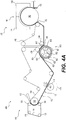
- FIG. 6 shows an example papermaking machine 600 of a third embodiment of our invention.
- a molding nip 610 formed between the patterned cylinder 420 and a Yankee drum 142, and a moist nascent web 102 is molded by the patterned cylinder 420 to form a molded web 102 in the molding nip 610.
- the nascent web 102 is formed similarly to the CWP papermaking machine 100 described above with reference to Figure 1 (additional features of the Yankee drying section 140 are also discussed in the first embodiment with reference to Figure 4 and drying section 450).
- the press nip 130 and Yankee dryer section 140 are used to dewater the web 102 to form a moist nascent web 102.
- the moist nascent web 102 will have a consistency from about thirty percent solids to about sixty percent solids, and more preferably from about forty percent solids to about fifty-five percent solids, as it enters the molding nip 610.
- the moist nascent web 102 is transferred from the Yankee drum 142 to the patterned cylinder 420 in the molding nip 610.
- the moist nascent web 102 may be transferred from the Yankee drum 142 to the patterned cylinder 420 by a rush transfer.
- the moist nascent web 102 is creped at a ratio of about twenty percent to about two hundred percent, and more preferably from about sixty percent to about one hundred fifteen percent.
- the patterned surface 422 of the patterned cylinder 420 may be permeable to allow a vacuum to be drawn by a vacuum box 432 in the molding nip 610 to assist both in transfer and molding of the web 102.
- a permeable patterned surface 422 is used, other features such as the blow box 446 and cleaning section 460 may also be used.
- the molded web 102 is transferred from the patterned cylinder 420 to a drying section 620 to form a dried web 102.
- a non-compactive drying process such as a the TAD drying section 530 shown and described above in the second embodiment with reference to Figure 5 , is used to avoid altering the imparted pattern to the molded web 102.
- the molded web 102 may be transferred to the TAD fabric 216 in the second transfer nip 440 described above in the second embodiment with reference to Figure 5 .
- the dried web 102 is removed from the TAD fabric 216 where it is then wound on a reel (not shown) to form a parent roll 190.
- Multiple patterned cylinders 420 may be used in the embodiments discussed above to mold and impart a pattern to the nascent (moist nascent) web 102.
- a first, background pattern may be imparted by a first patterned cylinder 420 and then a second, signature pattern may be superimposed over the background pattern by a second patterned cylinder 420.
- both patterned cylinders 420 may be located upstream of the drying section (450, 530, 620, respectively) and process the web 102 without intermediate drying between the two patterned cylinders 420, resulting in both patterns being imparted to the web 102 at similar consistencies.
- Another variation using two patterned cylinders 420 may be a combination of the first embodiment and the third embodiment.
- the first patterned cylinder 420 may be located and operated as described in the first embodiment with reference to Figure 4 .
- the Yankee drum 142 and the second patterned cylinder 420 may be operated as described in the third embodiment with reference to Figure 6 .
- the molded web 102 may then be dried to form a dried web 102 as described in the third embodiment with reference to Figure 6 .
- the papermaking machine employing this variation will be configured such that both the first and second patterns are imparted to the same surface of the paper web 102.
- This invention can be used to produce desirable paper products, such as paper towels and bath tissue.
- this invention is applicable to the paper products industry.
Landscapes
- Engineering & Computer Science (AREA)
- Mechanical Engineering (AREA)
- Paper (AREA)
Claims (15)
- Verfahren zur Herstellung einer Faserplatte, wobei das Verfahren Folgendes umfasst:(a) Bilden einer naszierenden Bahn (102) aus einer wässrigen Lösung von Papierherstellungsfasern;(b) Bewegen der naszierenden Bahn (102) auf eine Übertragungsfläche (116);(c) In-Kontakt-Bringen einer gemusterten Fläche (422) eines gemusterten Zylinders (420) mit der naszierenden Bahn (102), die eine Konsistenz von ungefähr zwanzig Prozent Feststoffen bis ungefähr siebzig Prozent Feststoffen aufweist, wobei die gemusterte Fläche (422) (i) auf der Außenseite des gemusterten Zylinders (420) gebildet ist und (ii) mindestens eine einer Vielzahl von Aussparungen (424) und einer Vielzahl von Vorsprüngen (425) aufweist;(d) Transportieren der naszierenden Bahn (102) zwischen der Übertragungsfläche (116) und der gemusterten Fläche (422) über eine Bogenlänge der gemusterten Fläche (422), wobei die Bogenlänge mindestens einen Abschnitt eines Formungsbereichs (430) bildet;(e) Übertragen der naszierenden Bahn (102) von der Übertragungsfläche (116) auf die gemusterte Fläche (422) des gemusterten Zylinders (420) im Formungsbereich (430), so dass die Papierherstellungsfasern der naszierenden Bahn (102) (i) auf der gemusterten Fläche (422) neu verteilt und (ii) durch mindestens eine der Vielzahl von Aussparungen (424) und die Vielzahl von Vorsprüngen (425) der gemusterten Fläche (422) im Formungsbereich (430) gestaltet sind, um eine geformte Papierbahn (102) zu bilden;(f) Übertragen der geformten Papierbahn (102) auf eine Aufnahmefläche (442, 216); und(g) Trocknen der geformten Papierbahn (102) in einem Trocknungsabschnitt (450, 530, 620), um eine Faserplatte zu bilden.
- Verfahren nach Anspruch 1, wobei im Schritt des In-Kontakt-Bringens einer gemusterten Fläche (422) eines gemusterten Zylinders (420) mit der naszierenden Bahn (102) die naszierende Bahn (102) eine Konsistenz von ungefähr zwanzig Prozent Feststoffen bis ungefähr fünfunddreißig Prozent Feststoffen aufweist.
- Verfahren nach Anspruch 1, weiter umfassend Entwässern der naszierenden Bahn (102), um eine entwässerte Bahn zu bilden.
- Verfahren nach Anspruch 3, wobei der Entwässerungsschritt das Entwässern der naszierenden Bahn (102) unter Verwendung von einem einer Schuhpresse, einer Rollpresse, einer Vakuumentwässerung, einer Verschiebungspresse und thermischem Trocknen umfasst, und
wobei der Entwässerungsschritt vor dem Schritt des Übertragens der naszierenden Bahn (102) auf die durchlässige gemusterte Fläche (422) des gemusterten Zylinders (420) erfolgt. - Verfahren nach Anspruch 3, wobei die entwässerte Bahn eine Konsistenz von ungefähr dreißig Prozent Feststoffen bis ungefähr sechzig Prozent Feststoffen aufweist.
- Verfahren nach Anspruch 1, wobei der Transportierschritt das Pressen der naszierenden Bahn (102) in die gemusterte Fläche (422) des gemusterten Zylinders (420) beinhaltet, und
wobei die naszierende Bahn (102) mit einer Kraft von ungefähr einhundertsechsundfünfzig kPa (ungefähr acht Pfund psig) bis ungefähr dreihundertzweiundzwanzig kPa (ungefähr zweiunddreißig Pfund psig) gepresst wird. - Verfahren nach Anspruch 1, weiter umfassend:(h) Bewegen der Übertragungsfläche (116) mit einer Übertragungsflächengeschwindigkeit; und(i) Drehen der gemusterten Fläche (422) des gemusterten Zylinders (420) mit einer Zylindergeschwindigkeit, wobei die Übertragungsflächengeschwindigkeit schneller als die Zylindergeschwindigkeit ist.
- Verfahren nach Anspruch 1, weiter umfassend Anwenden eine Vakuums auf einen Vakuumbereich, wobei das Vakuum angewendet wird, um die geformte Bahn (102) von der gemusterten Fläche (422) des gemusterten Zylinders (420) auf die Aufnahmefläche (216) zu ziehen, wobei die geformte Bahn (102) von der gemusterten Fläche (422) des gemusterten Zylinders (420) auf die Aufnahmefläche (216) im Vakuumbereich übertragen wird, vorzugsweise die Aufnahmefläche (216) ein Gewebe oder einen Gürtel umfasst und das Vakuum durch eine Saugrolle angewendet wird.
- Verfahren nach Anspruch 1, weiter umfassend:(h) Drehen der durchlässigen gemusterten Fläche (422) des gemusterten Zylinders (420) mit einer Zylindergeschwindigkeit; und(i) Bewegen der Aufnahmefläche (442, 216) mit einer Aufnahmeflächengeschwindigkeit, wobei die Zylindergeschwindigkeit schneller als die Aufnahmeflächengeschwindigkeit ist.
- Verfahren nach Anspruch 1, wobei der Trocknungsabschnitt (450, 530) einen Yankee-Zylinder (140) und ein Durchluft-Trocknungsgewebe umfasst, und das Durchluft-Trocknungsgewebe (216) die Aufnahmefläche ist, und
wobei der Trocknungsschritt das Trocknen der geformten Papierbahn (102) unter Verwendung des Yankee-Zylinders (140) beinhaltet. - Verfahren nach Anspruch 1, wobei die gemusterte Fläche (422) eine durchlässige gemusterte Fläche (422) ist, wobei die durchlässige gemusterte Fläche (422) durchlässig für Luft ist, und
wobei der gemusterte Zylinder (420) eine Innenseite beinhaltet, vorzugsweise wobei das Verfahren weiter das Anwenden eines Vakuums über mindestens einen Abschnitt der Bogenlänge umfasst, wobei das Vakuum in der Innenseite des gemusterten Zylinders (420) angewendet wird, um zu verursachen, dass Luft durch die durchlässige gemusterte Fläche (422) in die Innenseite des gemusterten Zylinders (420) strömt. - Verfahren nach Anspruch 11, wobei das Vakuum von ungefähr siebzehn kPa (ungefähr fünf Zoll Quecksilbersäule) bis ungefähr fünfundachtzig kPa (ungefähr fünfundzwanzig Zoll Quecksilbersäule) beträgt.
- Verfahren nach Anspruch 11, weiter umfassend Anwenden von Luftüberdruck in der Innenseite des gemusterten Zylinders (420), um zu verursachen, dass Luft durch die durchlässige gemusterte Fläche (422) des gemusterten Zylinders (420) weg von der Innenseite des gemusterten Zylinders (420) in einer radialen Richtung strömt, wobei der Luftüberdruck angewendet wird, um die geformte Papierbahn (102) weg von der durchlässigen gemusterten Fläche (422) zu übertragen.
- Verfahren nach Anspruch 13, wobei der Luftüberdruck während der Übertragung der geformten Bahn (102) auf die Aufnahmefläche (442, 216) angewendet wird.
- Verfahren nach Anspruch 11, weiter umfassend Reinigen der durchlässigen gemusterten Fläche (422) des gemusterten Zylinders (420) an einer freien Fläche des gemusterten Zylinders (420) durch Richten eines Reinigungsmediums durch die durchlässige gemusterte Fläche (422) weg von der Innenseite des gemusterten Zylinders (420) in einer radialen Richtung der Formungsrolle, wobei das Reinigungsmedium mindestens eines von Luft, Wasser und einer Reinigungslösung beinhaltet.
Priority Applications (2)
| Application Number | Priority Date | Filing Date | Title |
|---|---|---|---|
| EP21184030.1A EP3913138B1 (de) | 2017-08-08 | 2018-07-27 | Verfahren zur herstellung von papierprodukten unter verwendung eines gemusterten zylinders |
| PL18743595T PL3665327T3 (pl) | 2017-08-08 | 2018-07-27 | Sposoby wytwarzania wyrobów papierowych przy użyciu wzorzystego cylindra |
Applications Claiming Priority (3)
| Application Number | Priority Date | Filing Date | Title |
|---|---|---|---|
| US201762542378P | 2017-08-08 | 2017-08-08 | |
| US16/023,451 US10697120B2 (en) | 2017-08-08 | 2018-06-29 | Methods of making paper products using a patterned cylinder |
| PCT/IB2018/055644 WO2019030603A1 (en) | 2017-08-08 | 2018-07-27 | METHODS OF MANUFACTURING PAPER PRODUCTS USING A STRUCTURED ROLL |
Related Child Applications (2)
| Application Number | Title | Priority Date | Filing Date |
|---|---|---|---|
| EP21184030.1A Division EP3913138B1 (de) | 2017-08-08 | 2018-07-27 | Verfahren zur herstellung von papierprodukten unter verwendung eines gemusterten zylinders |
| EP21184030.1A Division-Into EP3913138B1 (de) | 2017-08-08 | 2018-07-27 | Verfahren zur herstellung von papierprodukten unter verwendung eines gemusterten zylinders |
Publications (2)
| Publication Number | Publication Date |
|---|---|
| EP3665327A1 EP3665327A1 (de) | 2020-06-17 |
| EP3665327B1 true EP3665327B1 (de) | 2021-09-01 |
Family
ID=65271085
Family Applications (2)
| Application Number | Title | Priority Date | Filing Date |
|---|---|---|---|
| EP18743595.3A Active EP3665327B1 (de) | 2017-08-08 | 2018-07-27 | Verfahren zur herstellung von papierprodukten unter verwendung eines gemusterten zylinders |
| EP21184030.1A Active EP3913138B1 (de) | 2017-08-08 | 2018-07-27 | Verfahren zur herstellung von papierprodukten unter verwendung eines gemusterten zylinders |
Family Applications After (1)
| Application Number | Title | Priority Date | Filing Date |
|---|---|---|---|
| EP21184030.1A Active EP3913138B1 (de) | 2017-08-08 | 2018-07-27 | Verfahren zur herstellung von papierprodukten unter verwendung eines gemusterten zylinders |
Country Status (15)
| Country | Link |
|---|---|
| US (2) | US10697120B2 (de) |
| EP (2) | EP3665327B1 (de) |
| JP (1) | JP7219749B2 (de) |
| KR (1) | KR20200035939A (de) |
| CN (1) | CN110914495B (de) |
| BR (1) | BR112020002491A2 (de) |
| CA (1) | CA3064165A1 (de) |
| CL (1) | CL2020000285A1 (de) |
| ES (2) | ES2892309T3 (de) |
| FI (1) | FI3913138T3 (de) |
| HU (1) | HUE055949T2 (de) |
| MX (1) | MX2020001250A (de) |
| PL (1) | PL3665327T3 (de) |
| RU (1) | RU2768672C2 (de) |
| WO (1) | WO2019030603A1 (de) |
Families Citing this family (7)
| Publication number | Priority date | Publication date | Assignee | Title |
|---|---|---|---|---|
| JP6989511B2 (ja) * | 2016-02-08 | 2022-01-05 | ジーピーシーピー アイピー ホールディングス エルエルシー | モールディングロールを使用して紙製品を作製する方法 |
| KR20180114109A (ko) | 2016-02-08 | 2018-10-17 | 쥐피씨피 아이피 홀딩스 엘엘씨 | 성형 롤을 이용한 종이 제품의 제조 방법 |
| JP6930987B2 (ja) | 2016-02-08 | 2021-09-01 | ジーピーシーピー アイピー ホールディングス エルエルシー | 紙製品を作製するためのモールディングロール |
| US10697120B2 (en) * | 2017-08-08 | 2020-06-30 | Gpcp Ip Holdings Llc | Methods of making paper products using a patterned cylinder |
| IT202000020926A1 (it) | 2020-09-03 | 2022-03-03 | A Celli Paper Spa | Pressa a scarpa per carta e relativo metodo |
| JP7156652B1 (ja) * | 2021-11-24 | 2022-10-19 | 川之江造機株式会社 | 微細繊維シート製造装置 |
| WO2025111535A1 (en) * | 2023-11-22 | 2025-05-30 | Curt G. Joa, Inc. | Multi-piece transfer system assembly for use in manufacturing absorbent products |
Family Cites Families (30)
| Publication number | Priority date | Publication date | Assignee | Title |
|---|---|---|---|---|
| US3104197A (en) | 1959-06-29 | 1963-09-17 | Crown Zellerbach Corp | Extensible paper and the process of producing the same |
| JPS527306A (en) | 1975-07-08 | 1977-01-20 | Nippon Steel Corp | Method of cooling sintering cake |
| US4608108A (en) | 1982-11-08 | 1986-08-26 | The Celotex Corporation | Wet-end molding method and molded product |
| US4698257A (en) | 1982-11-08 | 1987-10-06 | The Celotex Corporation | Wet-end molded product |
| CA1213768A (en) | 1982-11-08 | 1986-11-12 | Celotex Corporation (The) | Wet-end molding method and molded product |
| US5411636A (en) | 1993-05-21 | 1995-05-02 | Kimberly-Clark | Method for increasing the internal bulk of wet-pressed tissue |
| US5704101A (en) | 1995-06-05 | 1998-01-06 | Kimberly-Clark Worldwide, Inc. | Creped and/or apertured webs and process for producing the same |
| JP3628467B2 (ja) * | 1997-02-28 | 2005-03-09 | 花王株式会社 | 嵩高紙製造装置及びそれを用いた嵩高紙の製造方法 |
| US6161303A (en) | 1998-10-29 | 2000-12-19 | Voith Sulzer Papiertechnik Patent Gmbh | Pressing apparatus having chamber end sealing |
| US6416631B1 (en) | 1998-10-29 | 2002-07-09 | Voith Sulzer Papiertechnik Patent Gmbh | Pressing apparatus having semipermeable membrane |
| US6248210B1 (en) | 1998-11-13 | 2001-06-19 | Fort James Corporation | Method for maximizing water removal in a press nip |
| CA2308050A1 (en) * | 1999-05-12 | 2000-11-12 | International Paper Company | Method and apparatus for dewatering a suction papermaking roll |
| JP3703711B2 (ja) | 2000-11-27 | 2005-10-05 | ユニ・チャーム株式会社 | 不織布の製造方法および製造装置 |
| US7494563B2 (en) | 2002-10-07 | 2009-02-24 | Georgia-Pacific Consumer Products Lp | Fabric creped absorbent sheet with variable local basis weight |
| US7789995B2 (en) | 2002-10-07 | 2010-09-07 | Georgia-Pacific Consumer Products, LP | Fabric crepe/draw process for producing absorbent sheet |
| US7442278B2 (en) | 2002-10-07 | 2008-10-28 | Georgia-Pacific Consumer Products Lp | Fabric crepe and in fabric drying process for producing absorbent sheet |
| US8398820B2 (en) | 2002-10-07 | 2013-03-19 | Georgia-Pacific Consumer Products Lp | Method of making a belt-creped absorbent cellulosic sheet |
| HK1079828B (en) | 2002-10-07 | 2009-04-30 | Gpcp Ip Holdings Llc | Process for making a creped cellulosic sheet |
| US7662257B2 (en) | 2005-04-21 | 2010-02-16 | Georgia-Pacific Consumer Products Llc | Multi-ply paper towel with absorbent core |
| US6855227B2 (en) | 2003-01-31 | 2005-02-15 | Voith Paper Patent Gmbh | Paper machine and method of dewatering a fiber web using displacement pressing and through air drying |
| US7186317B2 (en) | 2003-12-12 | 2007-03-06 | Kimberly-Clark Worldwide, Inc. | Method for producing soft bulky tissue |
| US8293072B2 (en) | 2009-01-28 | 2012-10-23 | Georgia-Pacific Consumer Products Lp | Belt-creped, variable local basis weight absorbent sheet prepared with perforated polymeric belt |
| ITFI20040102A1 (it) | 2004-04-29 | 2004-07-29 | Guglielmo Biagiotti | Metodo e dispositivo per la produzione di carta tissue |
| US7503998B2 (en) * | 2004-06-18 | 2009-03-17 | Georgia-Pacific Consumer Products Lp | High solids fabric crepe process for producing absorbent sheet with in-fabric drying |
| ITFI20050218A1 (it) | 2005-10-20 | 2007-04-21 | Guglielmo Biagiotti | Perfezionamenti ai metodi e dispositivi per la produzione di carte tissue e velo di carta da questi derivante |
| US8080130B2 (en) | 2008-02-01 | 2011-12-20 | Georgia-Pacific Consumer Products Lp | High basis weight TAD towel prepared from coarse furnish |
| JP6989511B2 (ja) | 2016-02-08 | 2022-01-05 | ジーピーシーピー アイピー ホールディングス エルエルシー | モールディングロールを使用して紙製品を作製する方法 |
| JP6930987B2 (ja) | 2016-02-08 | 2021-09-01 | ジーピーシーピー アイピー ホールディングス エルエルシー | 紙製品を作製するためのモールディングロール |
| KR20180114109A (ko) | 2016-02-08 | 2018-10-17 | 쥐피씨피 아이피 홀딩스 엘엘씨 | 성형 롤을 이용한 종이 제품의 제조 방법 |
| US10697120B2 (en) * | 2017-08-08 | 2020-06-30 | Gpcp Ip Holdings Llc | Methods of making paper products using a patterned cylinder |
-
2018
- 2018-06-29 US US16/023,451 patent/US10697120B2/en not_active Expired - Fee Related
- 2018-07-27 PL PL18743595T patent/PL3665327T3/pl unknown
- 2018-07-27 RU RU2019138529A patent/RU2768672C2/ru active
- 2018-07-27 ES ES18743595T patent/ES2892309T3/es active Active
- 2018-07-27 HU HUE18743595A patent/HUE055949T2/hu unknown
- 2018-07-27 CA CA3064165A patent/CA3064165A1/en active Pending
- 2018-07-27 BR BR112020002491-0A patent/BR112020002491A2/pt active Search and Examination
- 2018-07-27 EP EP18743595.3A patent/EP3665327B1/de active Active
- 2018-07-27 WO PCT/IB2018/055644 patent/WO2019030603A1/en not_active Ceased
- 2018-07-27 EP EP21184030.1A patent/EP3913138B1/de active Active
- 2018-07-27 MX MX2020001250A patent/MX2020001250A/es unknown
- 2018-07-27 JP JP2020502125A patent/JP7219749B2/ja active Active
- 2018-07-27 ES ES21184030T patent/ES2961723T3/es active Active
- 2018-07-27 FI FIEP21184030.1T patent/FI3913138T3/fi active
- 2018-07-27 CN CN201880047614.1A patent/CN110914495B/zh not_active Expired - Fee Related
- 2018-07-27 KR KR1020207000798A patent/KR20200035939A/ko not_active Abandoned
-
2020
- 2020-01-31 CL CL2020000285A patent/CL2020000285A1/es unknown
- 2020-04-17 US US16/851,181 patent/US11105044B2/en not_active Expired - Fee Related
Also Published As
| Publication number | Publication date |
|---|---|
| WO2019030603A1 (en) | 2019-02-14 |
| ES2892309T3 (es) | 2022-02-03 |
| ES2961723T3 (es) | 2024-03-13 |
| US20190048525A1 (en) | 2019-02-14 |
| RU2019138529A (ru) | 2021-09-10 |
| RU2019138529A3 (de) | 2021-09-10 |
| MX2020001250A (es) | 2020-03-20 |
| US10697120B2 (en) | 2020-06-30 |
| CA3064165A1 (en) | 2019-02-14 |
| EP3913138A1 (de) | 2021-11-24 |
| US20200240082A1 (en) | 2020-07-30 |
| HUE055949T2 (hu) | 2022-01-28 |
| FI3913138T3 (fi) | 2023-10-04 |
| BR112020002491A2 (pt) | 2020-07-28 |
| CL2020000285A1 (es) | 2020-09-11 |
| CN110914495A (zh) | 2020-03-24 |
| US11105044B2 (en) | 2021-08-31 |
| JP2020530074A (ja) | 2020-10-15 |
| CN110914495B (zh) | 2022-04-01 |
| EP3665327A1 (de) | 2020-06-17 |
| EP3913138B1 (de) | 2023-09-13 |
| RU2768672C2 (ru) | 2022-03-24 |
| KR20200035939A (ko) | 2020-04-06 |
| PL3665327T3 (pl) | 2021-11-08 |
| JP7219749B2 (ja) | 2023-02-08 |
Similar Documents
| Publication | Publication Date | Title |
|---|---|---|
| US11105044B2 (en) | Methods of making paper products using a patterned cylinder | |
| US11802375B2 (en) | Molding roll for making paper products | |
| US11732416B2 (en) | Method of making a molded paper web | |
| US11035077B2 (en) | Methods of making paper products using a molding roll |
Legal Events
| Date | Code | Title | Description |
|---|---|---|---|
| STAA | Information on the status of an ep patent application or granted ep patent |
Free format text: STATUS: UNKNOWN |
|
| STAA | Information on the status of an ep patent application or granted ep patent |
Free format text: STATUS: THE INTERNATIONAL PUBLICATION HAS BEEN MADE |
|
| PUAI | Public reference made under article 153(3) epc to a published international application that has entered the european phase |
Free format text: ORIGINAL CODE: 0009012 |
|
| STAA | Information on the status of an ep patent application or granted ep patent |
Free format text: STATUS: REQUEST FOR EXAMINATION WAS MADE |
|
| 17P | Request for examination filed |
Effective date: 20200305 |
|
| AK | Designated contracting states |
Kind code of ref document: A1 Designated state(s): AL AT BE BG CH CY CZ DE DK EE ES FI FR GB GR HR HU IE IS IT LI LT LU LV MC MK MT NL NO PL PT RO RS SE SI SK SM TR |
|
| AX | Request for extension of the european patent |
Extension state: BA ME |
|
| DAV | Request for validation of the european patent (deleted) | ||
| DAX | Request for extension of the european patent (deleted) | ||
| GRAP | Despatch of communication of intention to grant a patent |
Free format text: ORIGINAL CODE: EPIDOSNIGR1 |
|
| STAA | Information on the status of an ep patent application or granted ep patent |
Free format text: STATUS: GRANT OF PATENT IS INTENDED |
|
| INTG | Intention to grant announced |
Effective date: 20210317 |
|
| GRAS | Grant fee paid |
Free format text: ORIGINAL CODE: EPIDOSNIGR3 |
|
| GRAA | (expected) grant |
Free format text: ORIGINAL CODE: 0009210 |
|
| STAA | Information on the status of an ep patent application or granted ep patent |
Free format text: STATUS: THE PATENT HAS BEEN GRANTED |
|
| AK | Designated contracting states |
Kind code of ref document: B1 Designated state(s): AL AT BE BG CH CY CZ DE DK EE ES FI FR GB GR HR HU IE IS IT LI LT LU LV MC MK MT NL NO PL PT RO RS SE SI SK SM TR |
|
| REG | Reference to a national code |
Ref country code: GB Ref legal event code: FG4D |
|
| REG | Reference to a national code |
Ref country code: CH Ref legal event code: EP Ref country code: AT Ref legal event code: REF Ref document number: 1426375 Country of ref document: AT Kind code of ref document: T Effective date: 20210915 |
|
| REG | Reference to a national code |
Ref country code: DE Ref legal event code: R096 Ref document number: 602018022896 Country of ref document: DE |
|
| REG | Reference to a national code |
Ref country code: FI Ref legal event code: FGE |
|
| REG | Reference to a national code |
Ref country code: IE Ref legal event code: FG4D |
|
| REG | Reference to a national code |
Ref country code: SE Ref legal event code: TRGR |
|
| REG | Reference to a national code |
Ref country code: NL Ref legal event code: FP |
|
| REG | Reference to a national code |
Ref country code: LT Ref legal event code: MG9D |
|
| REG | Reference to a national code |
Ref country code: HU Ref legal event code: AG4A Ref document number: E055949 Country of ref document: HU |
|
| PG25 | Lapsed in a contracting state [announced via postgrant information from national office to epo] |
Ref country code: NO Free format text: LAPSE BECAUSE OF FAILURE TO SUBMIT A TRANSLATION OF THE DESCRIPTION OR TO PAY THE FEE WITHIN THE PRESCRIBED TIME-LIMIT Effective date: 20211201 Ref country code: LT Free format text: LAPSE BECAUSE OF FAILURE TO SUBMIT A TRANSLATION OF THE DESCRIPTION OR TO PAY THE FEE WITHIN THE PRESCRIBED TIME-LIMIT Effective date: 20210901 Ref country code: BG Free format text: LAPSE BECAUSE OF FAILURE TO SUBMIT A TRANSLATION OF THE DESCRIPTION OR TO PAY THE FEE WITHIN THE PRESCRIBED TIME-LIMIT Effective date: 20211201 Ref country code: RS Free format text: LAPSE BECAUSE OF FAILURE TO SUBMIT A TRANSLATION OF THE DESCRIPTION OR TO PAY THE FEE WITHIN THE PRESCRIBED TIME-LIMIT Effective date: 20210901 Ref country code: HR Free format text: LAPSE BECAUSE OF FAILURE TO SUBMIT A TRANSLATION OF THE DESCRIPTION OR TO PAY THE FEE WITHIN THE PRESCRIBED TIME-LIMIT Effective date: 20210901 |
|
| REG | Reference to a national code |
Ref country code: ES Ref legal event code: FG2A Ref document number: 2892309 Country of ref document: ES Kind code of ref document: T3 Effective date: 20220203 |
|
| PG25 | Lapsed in a contracting state [announced via postgrant information from national office to epo] |
Ref country code: LV Free format text: LAPSE BECAUSE OF FAILURE TO SUBMIT A TRANSLATION OF THE DESCRIPTION OR TO PAY THE FEE WITHIN THE PRESCRIBED TIME-LIMIT Effective date: 20210901 Ref country code: GR Free format text: LAPSE BECAUSE OF FAILURE TO SUBMIT A TRANSLATION OF THE DESCRIPTION OR TO PAY THE FEE WITHIN THE PRESCRIBED TIME-LIMIT Effective date: 20211202 |
|
| PG25 | Lapsed in a contracting state [announced via postgrant information from national office to epo] |
Ref country code: IS Free format text: LAPSE BECAUSE OF FAILURE TO SUBMIT A TRANSLATION OF THE DESCRIPTION OR TO PAY THE FEE WITHIN THE PRESCRIBED TIME-LIMIT Effective date: 20220101 Ref country code: SM Free format text: LAPSE BECAUSE OF FAILURE TO SUBMIT A TRANSLATION OF THE DESCRIPTION OR TO PAY THE FEE WITHIN THE PRESCRIBED TIME-LIMIT Effective date: 20210901 Ref country code: SK Free format text: LAPSE BECAUSE OF FAILURE TO SUBMIT A TRANSLATION OF THE DESCRIPTION OR TO PAY THE FEE WITHIN THE PRESCRIBED TIME-LIMIT Effective date: 20210901 Ref country code: RO Free format text: LAPSE BECAUSE OF FAILURE TO SUBMIT A TRANSLATION OF THE DESCRIPTION OR TO PAY THE FEE WITHIN THE PRESCRIBED TIME-LIMIT Effective date: 20210901 Ref country code: PT Free format text: LAPSE BECAUSE OF FAILURE TO SUBMIT A TRANSLATION OF THE DESCRIPTION OR TO PAY THE FEE WITHIN THE PRESCRIBED TIME-LIMIT Effective date: 20220103 Ref country code: EE Free format text: LAPSE BECAUSE OF FAILURE TO SUBMIT A TRANSLATION OF THE DESCRIPTION OR TO PAY THE FEE WITHIN THE PRESCRIBED TIME-LIMIT Effective date: 20210901 Ref country code: AL Free format text: LAPSE BECAUSE OF FAILURE TO SUBMIT A TRANSLATION OF THE DESCRIPTION OR TO PAY THE FEE WITHIN THE PRESCRIBED TIME-LIMIT Effective date: 20210901 |
|
| REG | Reference to a national code |
Ref country code: DE Ref legal event code: R097 Ref document number: 602018022896 Country of ref document: DE |
|
| PLBE | No opposition filed within time limit |
Free format text: ORIGINAL CODE: 0009261 |
|
| STAA | Information on the status of an ep patent application or granted ep patent |
Free format text: STATUS: NO OPPOSITION FILED WITHIN TIME LIMIT |
|
| PG25 | Lapsed in a contracting state [announced via postgrant information from national office to epo] |
Ref country code: DK Free format text: LAPSE BECAUSE OF FAILURE TO SUBMIT A TRANSLATION OF THE DESCRIPTION OR TO PAY THE FEE WITHIN THE PRESCRIBED TIME-LIMIT Effective date: 20210901 |
|
| 26N | No opposition filed |
Effective date: 20220602 |
|
| PG25 | Lapsed in a contracting state [announced via postgrant information from national office to epo] |
Ref country code: SI Free format text: LAPSE BECAUSE OF FAILURE TO SUBMIT A TRANSLATION OF THE DESCRIPTION OR TO PAY THE FEE WITHIN THE PRESCRIBED TIME-LIMIT Effective date: 20210901 |
|
| PG25 | Lapsed in a contracting state [announced via postgrant information from national office to epo] |
Ref country code: MC Free format text: LAPSE BECAUSE OF FAILURE TO SUBMIT A TRANSLATION OF THE DESCRIPTION OR TO PAY THE FEE WITHIN THE PRESCRIBED TIME-LIMIT Effective date: 20210901 |
|
| REG | Reference to a national code |
Ref country code: CH Ref legal event code: PL |
|
| REG | Reference to a national code |
Ref country code: AT Ref legal event code: UEP Ref document number: 1426375 Country of ref document: AT Kind code of ref document: T Effective date: 20210901 |
|
| REG | Reference to a national code |
Ref country code: BE Ref legal event code: MM Effective date: 20220731 |
|
| PG25 | Lapsed in a contracting state [announced via postgrant information from national office to epo] |
Ref country code: LU Free format text: LAPSE BECAUSE OF NON-PAYMENT OF DUE FEES Effective date: 20220727 Ref country code: LI Free format text: LAPSE BECAUSE OF NON-PAYMENT OF DUE FEES Effective date: 20220731 Ref country code: CH Free format text: LAPSE BECAUSE OF NON-PAYMENT OF DUE FEES Effective date: 20220731 |
|
| PG25 | Lapsed in a contracting state [announced via postgrant information from national office to epo] |
Ref country code: BE Free format text: LAPSE BECAUSE OF NON-PAYMENT OF DUE FEES Effective date: 20220731 |
|
| P01 | Opt-out of the competence of the unified patent court (upc) registered |
Effective date: 20230528 |
|
| PG25 | Lapsed in a contracting state [announced via postgrant information from national office to epo] |
Ref country code: IE Free format text: LAPSE BECAUSE OF NON-PAYMENT OF DUE FEES Effective date: 20220727 |
|
| PGFP | Annual fee paid to national office [announced via postgrant information from national office to epo] |
Ref country code: NL Payment date: 20230614 Year of fee payment: 6 Ref country code: IT Payment date: 20230612 Year of fee payment: 6 Ref country code: FR Payment date: 20230620 Year of fee payment: 6 |
|
| PGFP | Annual fee paid to national office [announced via postgrant information from national office to epo] |
Ref country code: SE Payment date: 20230613 Year of fee payment: 6 Ref country code: PL Payment date: 20230616 Year of fee payment: 6 |
|
| PGFP | Annual fee paid to national office [announced via postgrant information from national office to epo] |
Ref country code: TR Payment date: 20230726 Year of fee payment: 6 Ref country code: GB Payment date: 20230608 Year of fee payment: 6 Ref country code: FI Payment date: 20230712 Year of fee payment: 6 Ref country code: ES Payment date: 20230808 Year of fee payment: 6 Ref country code: CZ Payment date: 20230718 Year of fee payment: 6 Ref country code: AT Payment date: 20230626 Year of fee payment: 6 |
|
| PGFP | Annual fee paid to national office [announced via postgrant information from national office to epo] |
Ref country code: HU Payment date: 20230626 Year of fee payment: 6 Ref country code: DE Payment date: 20230531 Year of fee payment: 6 |
|
| PG25 | Lapsed in a contracting state [announced via postgrant information from national office to epo] |
Ref country code: MK Free format text: LAPSE BECAUSE OF FAILURE TO SUBMIT A TRANSLATION OF THE DESCRIPTION OR TO PAY THE FEE WITHIN THE PRESCRIBED TIME-LIMIT Effective date: 20210901 Ref country code: CY Free format text: LAPSE BECAUSE OF FAILURE TO SUBMIT A TRANSLATION OF THE DESCRIPTION OR TO PAY THE FEE WITHIN THE PRESCRIBED TIME-LIMIT Effective date: 20210901 |
|
| PG25 | Lapsed in a contracting state [announced via postgrant information from national office to epo] |
Ref country code: MT Free format text: LAPSE BECAUSE OF FAILURE TO SUBMIT A TRANSLATION OF THE DESCRIPTION OR TO PAY THE FEE WITHIN THE PRESCRIBED TIME-LIMIT Effective date: 20210901 |
|
| REG | Reference to a national code |
Ref country code: DE Ref legal event code: R119 Ref document number: 602018022896 Country of ref document: DE |
|
| REG | Reference to a national code |
Ref country code: SE Ref legal event code: EUG |
|
| REG | Reference to a national code |
Ref country code: NL Ref legal event code: MM Effective date: 20240801 |
|
| REG | Reference to a national code |
Ref country code: AT Ref legal event code: MM01 Ref document number: 1426375 Country of ref document: AT Kind code of ref document: T Effective date: 20240727 |
|
| GBPC | Gb: european patent ceased through non-payment of renewal fee |
Effective date: 20240727 |
|
| PG25 | Lapsed in a contracting state [announced via postgrant information from national office to epo] |
Ref country code: DE Free format text: LAPSE BECAUSE OF NON-PAYMENT OF DUE FEES Effective date: 20250201 |
|
| PG25 | Lapsed in a contracting state [announced via postgrant information from national office to epo] |
Ref country code: NL Free format text: LAPSE BECAUSE OF NON-PAYMENT OF DUE FEES Effective date: 20240801 Ref country code: FI Free format text: LAPSE BECAUSE OF NON-PAYMENT OF DUE FEES Effective date: 20240727 |
|
| PG25 | Lapsed in a contracting state [announced via postgrant information from national office to epo] |
Ref country code: HU Free format text: LAPSE BECAUSE OF NON-PAYMENT OF DUE FEES Effective date: 20240728 |
|
| PG25 | Lapsed in a contracting state [announced via postgrant information from national office to epo] |
Ref country code: AT Free format text: LAPSE BECAUSE OF NON-PAYMENT OF DUE FEES Effective date: 20240727 |
|
| PG25 | Lapsed in a contracting state [announced via postgrant information from national office to epo] |
Ref country code: FR Free format text: LAPSE BECAUSE OF NON-PAYMENT OF DUE FEES Effective date: 20240731 Ref country code: CZ Free format text: LAPSE BECAUSE OF NON-PAYMENT OF DUE FEES Effective date: 20240727 |
|
| PG25 | Lapsed in a contracting state [announced via postgrant information from national office to epo] |
Ref country code: GB Free format text: LAPSE BECAUSE OF NON-PAYMENT OF DUE FEES Effective date: 20240727 |
|
| PG25 | Lapsed in a contracting state [announced via postgrant information from national office to epo] |
Ref country code: IT Free format text: LAPSE BECAUSE OF NON-PAYMENT OF DUE FEES Effective date: 20240727 |
|
| REG | Reference to a national code |
Ref country code: ES Ref legal event code: FD2A Effective date: 20250901 |
|
| PG25 | Lapsed in a contracting state [announced via postgrant information from national office to epo] |
Ref country code: ES Free format text: LAPSE BECAUSE OF NON-PAYMENT OF DUE FEES Effective date: 20240728 |
|
| PG25 | Lapsed in a contracting state [announced via postgrant information from national office to epo] |
Ref country code: SE Free format text: LAPSE BECAUSE OF NON-PAYMENT OF DUE FEES Effective date: 20240728 |
|
| PG25 | Lapsed in a contracting state [announced via postgrant information from national office to epo] |
Ref country code: PL Free format text: LAPSE BECAUSE OF NON-PAYMENT OF DUE FEES Effective date: 20240727 |