EP3664550B1 - Datenübertragungsverfahren und -vorrichtung - Google Patents
Datenübertragungsverfahren und -vorrichtung Download PDFInfo
- Publication number
- EP3664550B1 EP3664550B1 EP18855840.7A EP18855840A EP3664550B1 EP 3664550 B1 EP3664550 B1 EP 3664550B1 EP 18855840 A EP18855840 A EP 18855840A EP 3664550 B1 EP3664550 B1 EP 3664550B1
- Authority
- EP
- European Patent Office
- Prior art keywords
- time
- frequency resource
- resource element
- modulation symbol
- interleaving
- Prior art date
- Legal status (The legal status is an assumption and is not a legal conclusion. Google has not performed a legal analysis and makes no representation as to the accuracy of the status listed.)
- Active
Links
Images


Classifications
-
- H—ELECTRICITY
- H04—ELECTRIC COMMUNICATION TECHNIQUE
- H04L—TRANSMISSION OF DIGITAL INFORMATION, e.g. TELEGRAPHIC COMMUNICATION
- H04L1/00—Arrangements for detecting or preventing errors in the information received
- H04L1/004—Arrangements for detecting or preventing errors in the information received by using forward error control
- H04L1/0056—Systems characterized by the type of code used
- H04L1/0071—Use of interleaving
-
- H—ELECTRICITY
- H04—ELECTRIC COMMUNICATION TECHNIQUE
- H04L—TRANSMISSION OF DIGITAL INFORMATION, e.g. TELEGRAPHIC COMMUNICATION
- H04L27/00—Modulated-carrier systems
- H04L27/0008—Modulated-carrier systems arrangements for allowing a transmitter or receiver to use more than one type of modulation
-
- H—ELECTRICITY
- H04—ELECTRIC COMMUNICATION TECHNIQUE
- H04L—TRANSMISSION OF DIGITAL INFORMATION, e.g. TELEGRAPHIC COMMUNICATION
- H04L1/00—Arrangements for detecting or preventing errors in the information received
- H04L1/004—Arrangements for detecting or preventing errors in the information received by using forward error control
- H04L1/0041—Arrangements at the transmitter end
- H04L1/0043—Realisations of complexity reduction techniques, e.g. use of look-up tables
-
- H—ELECTRICITY
- H04—ELECTRIC COMMUNICATION TECHNIQUE
- H04L—TRANSMISSION OF DIGITAL INFORMATION, e.g. TELEGRAPHIC COMMUNICATION
- H04L5/00—Arrangements affording multiple use of the transmission path
- H04L5/003—Arrangements for allocating sub-channels of the transmission path
- H04L5/0048—Allocation of pilot signals, i.e. of signals known to the receiver
- H04L5/0051—Allocation of pilot signals, i.e. of signals known to the receiver of dedicated pilots, i.e. pilots destined for a single user or terminal
-
- H—ELECTRICITY
- H04—ELECTRIC COMMUNICATION TECHNIQUE
- H04W—WIRELESS COMMUNICATION NETWORKS
- H04W72/00—Local resource management
- H04W72/04—Wireless resource allocation
- H04W72/044—Wireless resource allocation based on the type of the allocated resource
- H04W72/0446—Resources in time domain, e.g. slots or frames
-
- H—ELECTRICITY
- H04—ELECTRIC COMMUNICATION TECHNIQUE
- H04W—WIRELESS COMMUNICATION NETWORKS
- H04W72/00—Local resource management
- H04W72/04—Wireless resource allocation
- H04W72/044—Wireless resource allocation based on the type of the allocated resource
- H04W72/0453—Resources in frequency domain, e.g. a carrier in FDMA
-
- H—ELECTRICITY
- H04—ELECTRIC COMMUNICATION TECHNIQUE
- H04W—WIRELESS COMMUNICATION NETWORKS
- H04W72/00—Local resource management
- H04W72/20—Control channels or signalling for resource management
- H04W72/23—Control channels or signalling for resource management in the downlink direction of a wireless link, i.e. towards a terminal
-
- H—ELECTRICITY
- H04—ELECTRIC COMMUNICATION TECHNIQUE
- H04W—WIRELESS COMMUNICATION NETWORKS
- H04W76/00—Connection management
- H04W76/20—Manipulation of established connections
- H04W76/27—Transitions between radio resource control [RRC] states
-
- H—ELECTRICITY
- H04—ELECTRIC COMMUNICATION TECHNIQUE
- H04W—WIRELESS COMMUNICATION NETWORKS
- H04W80/00—Wireless network protocols or protocol adaptations to wireless operation
- H04W80/02—Data link layer protocols
-
- H—ELECTRICITY
- H04—ELECTRIC COMMUNICATION TECHNIQUE
- H04L—TRANSMISSION OF DIGITAL INFORMATION, e.g. TELEGRAPHIC COMMUNICATION
- H04L1/00—Arrangements for detecting or preventing errors in the information received
- H04L1/0001—Systems modifying transmission characteristics according to link quality, e.g. power backoff
- H04L1/0009—Systems modifying transmission characteristics according to link quality, e.g. power backoff by adapting the channel coding
-
- H—ELECTRICITY
- H04—ELECTRIC COMMUNICATION TECHNIQUE
- H04L—TRANSMISSION OF DIGITAL INFORMATION, e.g. TELEGRAPHIC COMMUNICATION
- H04L1/00—Arrangements for detecting or preventing errors in the information received
- H04L1/004—Arrangements for detecting or preventing errors in the information received by using forward error control
- H04L1/0075—Transmission of coding parameters to receiver
Definitions
- This application relates to the communications field, and in particular, to a data transmission method and a device.
- a transmission time interval transmission time interval
- transport block transport block
- TB transport block
- Steps such as cyclic redundancy check (cyclic redundancy check, CRC) bit addition, code block segmentation (code block segmentation), channel coding (channel coding), rate matching (rate matching), and symbol modulation (modulation) are performed on information bits of a TB.
- symbols obtained through modulation are mapped onto scheduled time-frequency resources.
- interleaving the symbols obtained through modulation is considered as a feasible method.
- an existing method for interleaving the symbols obtained through modulation is relatively complex. Consequently, data demodulation performance is affected.
- CN102082600A provides a relay link downlink control information configuration method, a transmission base station, a relay station and a method.
- the transmission method comprises the following steps: the base station transmits a relay link physical downlink control channel on N1 continuously or discretely distributed control channel units while sending downlink control information to the relay station; each control channel unit comprises N2 resource unit groups, and each resource unit group comprises N3 effective resource units; or each control channel unit comprises N4 effective resource units.
- US8254245B2 discloses a method for transmitting a downlink control channel in a mobile communication system and a method for mapping the control channel to physical resources using a block interleaver are provided.
- information bits are modulated to generate one or more modulation symbols according to a specific modulation scheme, the modulation symbols are interleaved using a block interleaver, and the interleaved modulated symbols are mapped to resource elements allocated for transmission of at least one control channel in a subframe, thereby transmitting the at least one control channel.
- This application provides a data transmission method and a device according to the independent claims, to reduce complexity of interleaving modulation symbols.
- a data transmission method includes:
- one or a limited quantity of specific sizes of the time-frequency resource element group can be determined by being agreed on in the protocol or based on the transmission parameter. Therefore, computational complexity during chip processing can be simplified, and a prior-art problem of high complexity caused by interleaving performed by using a code block (code block, CB) as a unit can be resolved.
- code block code block
- the transmit end device may be a network device, or may be a terminal device.
- the transmit end device is a terminal device, and a receive end device is a network device.
- the transmit end device is a network device, and the receive end device is a terminal device.
- the to-be-transmitted modulation symbol sequence may be a modulation symbol sequence of a layer.
- the modulation symbol sequence may be a modulation symbol sequence obtained after layer mapping, or may be a modulation symbol sequence obtained, before layer mapping, through grouping based on layer mapping before layer mapping.
- the time-frequency resource element corresponds to a minimum interleaving unit.
- modulation symbols carried on a time-frequency resource element are consecutive modulation symbols in the modulation symbol sequence.
- one time-frequency resource element includes two REs
- one modulation symbol group includes two modulation symbols.
- a modulation symbol group carried on the time-frequency resource element includes two modulation symbols
- the two modulation symbols carried on the two REs are two consecutive modulation symbols in the to-be-transmitted modulation symbol sequence after interleaving processing.
- the size of the time-frequency resource element group may indicate a size of the interleaving unit.
- modulation symbols carried on one interleaving unit namely, one time-frequency resource element group
- one time-frequency resource element group includes five time-frequency resource elements, and correspondingly, the time-frequency resource element group is configured to carry five modulation symbol groups.
- the to-be-transmitted modulation symbol sequence includes 24 consecutive modulation symbol sequence groups, namely, a modulation symbol group #1 to a modulation symbol group #24.
- the five modulation symbol groups carried on the time-frequency resource element group are inconsecutive modulation symbol groups.
- the five modulation symbol groups are five completely inconsecutive modulation symbol groups, for example, the modulation symbol group #1, the modulation symbol group #5, the modulation symbol group #9, the modulation symbol group #13, and the modulation symbol group #18.
- five modulation symbol groups carried on one interleaving unit may include partially consecutive modulation symbol groups, but the five modulation symbol groups are not completely consecutive.
- the five modulation symbol groups include the modulation symbol group #1, the modulation symbol group #2, the modulation symbol group #8, the modulation symbol group 9, and the modulation symbol group #18.
- the bit sequence is a bit sequence of each layer that is obtained after code block concatenation and before modulation, to be specific, by grouping, based on layer mapping after modulation, bit sequences that are before modulation.
- the plurality of time-frequency resource element groups include all or some frequency domain resources on at least one orthogonal frequency division multiplexing (orthogonal frequency division multiplexing, OFDM) symbol.
- the at least one OFDM symbol may be one OFDM symbol, two OFDM symbols, ..., or 14 OFDM symbols.
- the frequency domain resource is a frequency domain resource within a scheduling bandwidth range. It should be understood that a frequency domain bandwidth on the OFDM symbol may be configured by a network device or preset in a system. This is not limited in this first aspect.
- the frequency domain bandwidth on the OFMD symbol may include at least two subcarriers, for example, include 12 subcarriers, 24 subcarriers, or 36 subcarriers. This first aspect is not limited thereto.
- the frequency domain resource bandwidth on the OFDM symbol is 36 subcarriers.
- the plurality of time-frequency resource element groups may include all the frequency domain resources on the at least one OFDM symbol, to be specific, 36 subcarriers; or may include some frequency domain resources, for example, 24 subcarriers, 12 subcarriers, or 8 subcarriers. This embodiment of this application is not limited thereto.
- the size of the time-frequency resource element group may be agreed on in the protocol.
- the size of the interleaving unit is agreed on in the protocol.
- the transmit end device may perform interleaving processing based on the interleaving unit specified in the protocol, unlike the prior art in which a CB size is determined through calculation and then interleaving is performed.
- a receive end may also directly perform de-interleaving processing based on the interleaving unit specified in the protocol. Therefore, in this first aspect, interleaving complexity can be reduced, and system performance can be improved.
- the size of the time-frequency resource element group is determined based on the transmission parameter, where the transmission parameter includes at least one of the following parameters: a scheduling bandwidth, a delay spread, and a moving speed of a terminal device.
- the method further includes: determining, by the transmit end device based on a preset correspondence between the transmission parameter and the size of the time-frequency resource element group, a size of the time-frequency resource element group that corresponds to a current transmission parameter.
- the size of the time-frequency resource element group is determined based on the transmission parameter, where the transmission parameter includes at least one of the following parameters: the scheduling bandwidth, the delay spread, and the moving speed of the terminal device.
- the transmit end device is a network device
- the receive end device is a terminal device
- the method further includes:
- the transmit end device is a terminal device
- the receive end device is a network device
- the method further includes: receiving, by the transmit end device, interleaving indication information sent by the receive end device, where the interleaving indication information indicates the size of the time-frequency resource group.
- the network device determines the size of the time-frequency resource group based on the transmission parameter, and the network device sends the interleaving indication information to the terminal device by using signaling, where the interleaving indication information indicates the size of the time-frequency resource group.
- the network device may flexibly determine, based on the transmission parameter, the size of the time-frequency resource group that corresponds to the transmission parameter, and can determine different sizes of the time-frequency resource group based on different values of the parameter, to meet interleaving requirements in different scenarios.
- the interleaving indication information is sent by using radio resource control RRC signaling, a media access control control element MAC-CE, or downlink control information DCI.
- the modulation symbol sequence includes a modulation symbol of a data transport block and a modulation symbol of a reference signal included in a scheduling resource corresponding to the data transport block, and the time-frequency resource element group is a physical time-frequency resource element group.
- the physical time-frequency resource element may be used to carry the modulation symbol of the data transmission block, and may also be used to carry the modulation symbol of the reference signal.
- a relatively large interleaving unit may be used for interleaving.
- the relatively large interleaving unit is used, so that after interleaving, a location of the reference signal remains unchanged, and can be prevented from being affected.
- all OFDM symbols may be interleaved by using a same interleaving solution, so that implementation complexity is low.
- the modulation symbol sequence includes only a modulation symbol of a data transport block
- the time-frequency resource element group is a logical time-frequency resource element group
- the logical time-frequency resource element group includes a time-frequency resource element that is of a physical time-frequency resource and that is configured to carry only the modulation symbol of the data transport block
- the physical time-frequency resource includes the time-frequency resource element used to carry the modulation symbol of the data transport block and a time-frequency resource element used to carry a modulation symbol of a reference signal included in a scheduling resource corresponding to the data transport block.
- a modulation symbol sequence may not include the modulation symbol of the reference signal, but include only a modulation symbol of a data transport block.
- the plurality of time-frequency resource groups configured to carry the to-be-transmitted modulation symbol sequence are logical time-frequency resource element groups, and the logical time-frequency resource element group includes a time-frequency resource element that is of a physical time-frequency resource and that is configured to carry only the modulation symbol of the data transport block
- the reference signal is skipped, and modulation symbols of the data transport block are interleaved in the logical resource element group without being affected by the reference signal.
- a base station and UE are very clear about a location of a pilot frequency, implementation complexity is low.
- the modulation symbol sequence includes only a modulation symbol of a data transport block, and the time-frequency resource element group is a physical time-frequency resource element group.
- a relatively small interleaving unit is used for interleaving.
- the relatively small interleaving unit is used, so that an interleaving depth can be increased, and a diversity gain can be increased.
- all OFDM symbols may be interleaved by using a same interleaving solution, and in this embodiment of this application, the relatively small interleaving unit is used, so that the interleaving depth can be increased, and the diversity gain can be increased.
- the modulation symbol sequence includes a first modulation symbol sequence and a second modulation symbol sequence.
- the plurality of time-frequency resource element groups include a first time-frequency resource element group set and a second time-frequency resource element group set.
- the first time-frequency resource element group set is used to carry the first modulation symbol sequence.
- the second time-frequency resource element group set is used to carry the second modulation symbol sequence.
- the first time-frequency resource element group set includes at least two first time-frequency resource element groups.
- the first time-frequency resource element group includes N 1 first time-frequency resource elements, where N 1 is an integer greater than or equal to 2.
- the second time-frequency resource element group set includes at least two second time-frequency resource element groups.
- the second time-frequency resource element group includes N 2 second time-frequency resource elements, where N 2 is an integer greater than or equal to 2.
- One first time-frequency resource element is used to carry one first modulation symbol group.
- One second time-frequency resource element is used to carry one second modulation symbol group.
- a quantity of resource elements REs included in the first time-frequency resource element is different from that of resource elements REs included in the second time-frequency resource element.
- the performing, by the transmit end device, interleaving processing on the modulation symbol sequence by using the time-frequency resource element group as an interleaving unit, to obtain an order in which the modulation symbol sequence is mapped onto the plurality of time-frequency resource element groups includes: performing, by the transmit end device, interleaving processing on the first modulation symbol sequence by using the first time-frequency resource element group as an interleaving unit, and performing interleaving processing on the second modulation symbol sequence by using the second time-frequency resource element group as an interleaving unit, to obtain a first order in which the first modulation symbol sequence is mapped onto the first time-frequency resource element group set and a second order in which the second modulation symbol sequence is mapped onto the second time-frequency resource element group set, where a plurality of consecutive first modulation symbol groups in the first modulation symbol sequence are mapped onto the at least two first time-frequency resource element groups in the first time-frequency resource element group set, and a plurality of consecutive second modulation symbol groups in the second modulation symbol sequence are
- a relatively large interleaving unit such as the second time-frequency resource element may be used for a resource part that carries the reference signal
- a relatively small interleaving unit such as the first time-frequency resource element may be used for a resource part that does not carry the reference signal.
- interleaving processing is separately performed independently on two modulation symbol sequences, to obtain the first order and the second order in which the two modulation symbol sequences are respectively mapped onto the first time-frequency resource element group set and the second time-frequency resource element group set. Therefore, in this embodiment of this application, sizes of two resource element groups are set, so that it can be ensured that a maximum interleaving depth is obtained as much as possible through interleaving performed under a premise that a reference signal is included. Because the base station and the UE are very clear about the location of the pilot frequency, implementation complexity is still quite low.
- a data transmission method includes:
- one or a limited quantity of specific sizes of the time-frequency resource element group can be determined by being agreed on in the protocol or based on the transmission parameter. Therefore, computational complexity during chip processing can be simplified, and a prior-art problem of high complexity caused by interleaving performed by using a CB as a unit can be resolved.
- the data transmission method described from the perspective of the receive end device in the second aspect corresponds to the data transmission method described from the perspective of the transmit end device in the first aspect.
- the data transmission method described from the perspective of the receive end device in the second aspect corresponds to the data transmission method described from the perspective of the transmit end device in the first aspect.
- the modulation symbol sequence includes a modulation symbol of a data transport block and a modulation symbol of a reference signal included in a scheduling resource corresponding to the data transport block, and the time-frequency resource element group is a physical time-frequency resource element group.
- the modulation symbol sequence includes only a modulation symbol of a data transport block
- the time-frequency resource element group is a logical time-frequency resource element group
- the logical time-frequency resource element group includes a time-frequency resource element that is of a physical time-frequency resource and that is configured to carry only the modulation symbol of the data transport block
- the physical time-frequency resource includes the time-frequency resource element used to carry the modulation symbol of the data transport block and a time-frequency resource element used to carry a modulation symbol of a reference signal included in a scheduling resource corresponding to the data transport block.
- the modulation symbol sequence includes a first modulation symbol sequence and a second modulation symbol sequence
- the plurality of time-frequency resource element groups include a first time-frequency resource element group set and a second time-frequency resource element group set
- the first time-frequency resource element group set is used to carry the first modulation symbol sequence
- the second time-frequency resource element group set is used to carry the second modulation symbol sequence
- the first time-frequency resource element group set includes at least two first time-frequency resource element groups
- the first time-frequency resource element group includes N 1 first time-frequency resource elements
- N 1 is an integer greater than or equal to 2
- the second time-frequency resource element group set includes at least two second time-frequency resource element groups
- the second time-frequency resource element group includes N 2 second time-frequency resource elements
- N 2 is an integer greater than or equal to 2
- one first time-frequency resource element is used to carry one first modulation symbol group
- one second time-frequency resource element is used to carry one second modulation symbol group
- the performing, by the receive end device by using the time-frequency resource element group as an interleaving unit, de-interleaving processing on the modulation symbols transmitted by using the plurality of time-frequency resource element groups, to obtain the modulation symbol sequence includes: performing, by the receive end device by using the first time-frequency resource element group as an interleaving unit, de-interleaving processing on modulation symbols carried on the first time-frequency resource element group set, and performing, by using the second time-frequency resource element group as an interleaving unit, de-interleaving processing on modulation symbols carried on the second time-frequency resource element group set, to obtain the first modulation symbol sequence and the second modulation symbol sequence.
- the size of the time-frequency resource element group is determined based on the transmission parameter, where the transmission parameter includes at least one of the following parameters: a scheduling bandwidth, a delay spread, and a moving speed of a terminal device.
- the method further includes: determining, by the receive end device based on a preset correspondence between the transmission parameter and the size of the time-frequency resource element group, a size of the time-frequency resource element group that corresponds to a current transmission parameter.
- the size of the time-frequency resource element group is determined based on the transmission parameter, where the transmission parameter includes at least one of the following parameters: the scheduling bandwidth, the delay spread, and the moving speed of the terminal device.
- the method further includes:
- the receive end device is a terminal device
- the transmit end device is a network device
- the method further includes: receiving, by the receive end device, interleaving indication information sent by the transmit end device, where the interleaving indication information indicates the size of the time-frequency resource group.
- the interleaving indication information is sent by using radio resource control RRC signaling, a media access control control element MAC-CE, or downlink control information DCI.
- the plurality of time-frequency resource element groups include all or some frequency domain resources on at least one OFDM symbol.
- an interleaving method includes:
- the method before the generating, by a network device, interleaving indication information, the method further includes: determining, by the network device, the size of the interleaving unit based on a transmission parameter, where the transmission parameter includes at least one of the following parameters: a scheduling bandwidth, a delay spread, and a moving speed of a terminal device.
- the sending, by the network device, the interleaving indication information includes: sending, by the network device, the interleaving indication information by using radio resource control RRC signaling, a media access control control element MAC-CE, or downlink control information DCI.
- the network device may flexibly determine, based on the transmission parameter, a size of the time-frequency resource group that corresponds to the transmission parameter, and can determine different sizes of the time-frequency resource group based on different values of the parameter, to meet interleaving requirements in different scenarios, and a prior-art problem of high complexity caused by interleaving performed by using a CB as a unit can be resolved.
- an interleaving method includes:
- the receiving, by a terminal device, interleaving indication information includes: receiving, by the terminal device, the interleaving indication information sent by a network device by using radio resource control RRC signaling, a media access control control element MAC-CE, or downlink control information DCI.
- the network device may flexibly determine, based on a transmission parameter, a size of the time-frequency resource group that corresponds to the transmission parameter, and can determine different sizes of the time-frequency resource group based on different values of the parameter, to meet interleaving requirements in different scenarios, and a prior-art problem of high complexity caused by interleaving performed by using a CB as a unit can be resolved.
- an interleaving method includes:
- one or a limited quantity of specific sizes of the time-frequency resource element group can be determined by being agreed on in the protocol or based on the transmission parameter. Therefore, computational complexity during chip processing can be simplified, and a prior-art problem of high complexity caused by interleaving performed by using a CB as a unit can be resolved.
- a transmit end device includes modules or units configured to perform the method according to any one of the first aspect or the possible implementations of the first aspect, or modules or units configured to perform the communication method according to any one of the fifth aspect or the possible implementations of the fifth aspect.
- the transmit end device is a terminal device, and during downlink transmission, the transmit end device is a network device.
- a receive end device includes modules or units configured to perform the communication method according to any one of the second aspect or the possible implementations of the second aspect, or modules or units configured to perform the communication method according to any one of the sixth aspect or the possible implementations of the sixth aspect.
- the receive end device is a network device, and during downlink transmission, the receive end device is a terminal device.
- a network device includes modules or units configured to perform the method according to any one of the third aspect or the possible implementations of the third aspect.
- a terminal device includes modules or units configured to perform the communication method according to any one of the fourth aspect or the possible implementations of the fourth aspect.
- a terminal device includes a transceiver, a processor, and a memory.
- the processor is configured to control the transceiver to send and receive signals
- the memory is configured to store a computer program
- the processor is configured to invoke the computer program from the memory and run the computer program, so that the terminal device performs the method, performed by the terminal device, in the first aspect to the sixth aspect and the possible implementations of the first aspect to the sixth aspect.
- a network device includes a transceiver, a processor, and a memory.
- the processor is configured to control the transceiver to send and receive signals
- the memory is configured to store a computer program
- the processor is configured to invoke the computer program from the memory and run the computer program, so that the network device performs the method, performed by the network device, in the first aspect to the sixth aspect and the possible implementations of the first aspect to the sixth aspect.
- the network device may be implemented by using a chip.
- the terminal device may be implemented by using a chip.
- a computer program product includes a computer program (also referred to as code or an instruction).
- a computer program also referred to as code or an instruction.
- a computer is enabled to perform the method according to any one of the first aspect to the sixth aspect or the possible implementations of the first aspect to the sixth aspect.
- a computer readable medium stores a computer program (also referred to as code or an instruction).
- a computer program also referred to as code or an instruction.
- the computer program When the computer program is run on a computer, the computer is enabled to perform the method according to any one of the first aspect to the sixth aspect or the possible implementations of the first aspect to the sixth aspect.
- GSM global system for mobile communications
- CDMA code division multiple access
- WCDMA wideband code division multiple access
- GPRS general packet radio service
- LTE long term evolution
- FDD frequency division duplex
- TDD time division duplex
- UMTS universal mobile telecommunications system
- WiMAX worldwide interoperability for microwave access
- WiMAX worldwide interoperability for microwave access
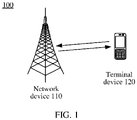
- FIG. 1 shows a communications system 100 to which the aspects of this application are applied.
- the communications system 100 may be any one of the foregoing communications systems.
- the communications system 100 may include at least one network device 110 and at least one terminal device 120.
- Each network device 1100 may provide communication coverage for a particular geographic area, and may communicate with the terminal device 120 (for example, UE) located in the coverage area (a cell).
- the terminal device in aspects of this application may be user equipment, an access terminal, a subscriber unit, a subscriber station, a mobile station, a mobile console, a remote station, a remote terminal, a mobile device, a user terminal, a terminal, a wireless communications device, a user agent, a user apparatus, or the like.
- the terminal device may alternatively be a cellular phone, a cordless phone, a session initiation protocol (session initiation protocol, SIP) phone, a wireless local loop (wireless local loop, WLL) station, a personal digital assistant (personal digital assistant, PDA), a handheld device having a wireless communication function, a computing device, another processing device connected to a wireless modem, a vehicle-mounted device, a wearable device, a terminal device in a future 5G network, a terminal device in a future evolved public land mobile network (public land mobile network, PLMN), or the like. This is not limited in the aspects of this application.
- the network device in aspects of this application may be a device configured to communicate with the terminal device.
- the network device may be a base transceiver station (base transceiver station, BTS) in the global system for mobile communications (global system of mobile communication, GSM) system or code division multiple access (code division multiple access, CDMA), or may be a NodeB (node B, NB) in the WCDMA system, or may be an evolved NodeB (evolutional node B, eNB or eNodeB) in the LTE system, or a radio controller in a cloud radio access network (cloud radio access network, CRAN).
- BTS base transceiver station
- GSM global system of mobile communication
- CDMA code division multiple access
- NodeB node B
- NB evolved NodeB
- evolutional node B, eNB or eNodeB evolved NodeB
- cloud radio access network cloud radio access network
- the network device may be a relay node, an access point, a vehicle-mounted device, a wearable device, a network-side device in the future 5G network, a network device in the future evolved public land mobile network (public land mobile network, PLMN), or the like.
- PLMN public land mobile network
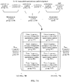
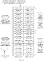
- FIG. 2 shows main steps of a data processing process performed before data is sent by using an OFDM symbol.
- steps such as CRC addition, code block segmentation, channel coding, rate matching, and symbol modulation are performed on data from an upper layer (for example, a MAC layer) undergoes, and finally modulated symbols are mapped onto a time-frequency resource for sending.
- an upper layer for example, a MAC layer
- OFDM transmission is multi-carrier transmission, and in the OFDM transmission, each modulation signal is limited to relatively narrow bandwidth. Therefore, when the OFDM transmission experiences a frequency selective channel condition, some modulation signals are completely in a frequency band with quite low instantaneous signal strength. If these signals all belong to a same decoding unit, bit errors of the signals may be beyond an error correction capability of forward error correcting code (forward error correction, FEC). Consequently, an entire transport block cannot be correctly received.
- FEC forward error correcting code
- modulation symbols are usually interleaved by using a code block (CB) as a unit.
- CB code block
- modulation symbols generated through modulation are first mapped onto a layer, then mapped onto a frequency domain, finally mapped onto a time domain, and interleaved in the mapping process, so that an effect of decentralized distribution of data of a same CB in frequency domain is achieved.
- data of one CB may be centralized on a time-domain symbol or consecutive time-domain symbols. This helps a receive end perform fast demodulation.
- one CB includes 10 modulation symbols.
- a distribution case of modulation symbols of CBs in the three OFDM symbols before interleaving is that the first 10 REs in an OFDM symbol 1 correspond to a CB 1, the last two REs correspond to a CB 2, and so on.
- an interleaving range is in each OFDM symbol.
- the first five REs and the seventh to the eleventh REs in the interleaved OFDM symbol 1 correspond to the CB 1
- the sixth RE and the twelfth RE correspond to the CB 2, and so on. It can be learned from FIG.
- the embodiments of this application skillfully provide an interleaving method, so that all OFDM symbols use one or two same interleaving solutions, to reduce interleaving complexity and improve system performance.
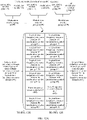
- FIG. 4 is a schematic flowchart of a data interleaving method according to an aspect of this application from the perspective of device interaction. The method shown in FIG. 4 includes the following steps.
- a transmit end device obtains a to-be-transmitted modulation symbol sequence in a plurality of time-frequency resource element groups.
- the time-frequency resource element group includes N time-frequency resource elements, N is an integer greater than or equal to 2, the time-frequency resource element includes at least one resource element (resource element, RE), one time-frequency resource element is used to carry one modulation symbol group, one modulation symbol group includes at least one modulation symbol, and a size of the time-frequency resource element group is agreed on in a protocol, or a size of the time-frequency resource element group is determined based on a transmission parameter.
- resource element resource element
- the transmit end device may be a network device, or may be a terminal device.
- the transmit end device is a terminal device, and a receive end device is a network device.
- the transmit end device is a network device, and the receive end device is a terminal device.
- the to-be-transmitted modulation symbol sequence may be a modulation symbol sequence of a layer.
- the modulation symbol sequence may be a modulation symbol sequence obtained after layer mapping, or may be a modulation symbol sequence obtained, before layer mapping, through grouping based on layer mapping. This aspect of this application is not limited thereto.
- the time-frequency resource element corresponds to a minimum interleaving unit.
- modulation symbols carried on one time-frequency resource element are consecutive modulation symbols in the modulation symbol sequence.
- one time-frequency resource element includes two REs, and correspondingly, one modulation symbol group includes two modulation symbols.
- a modulation symbol group carried on the time-frequency resource element includes two modulation symbols, and the two modulation symbols carried on the two REs are two consecutive modulation symbols in the to-be-transmitted modulation symbol sequence after interleaving processing.
- the size of the time-frequency resource element group may indicate a size of the interleaving unit.
- modulation symbols carried on one interleaving unit namely, one time-frequency resource element group
- one time-frequency resource element group includes five time-frequency resource elements, and correspondingly, the time-frequency resource element group is configured to carry five modulation symbol groups.
- the to-be-transmitted modulation symbol sequence includes 24 consecutive modulation symbol sequence groups, namely, a modulation symbol group #1 to a modulation symbol group #24.
- the five modulation symbol groups carried on the time-frequency resource element group are inconsecutive modulation symbol groups.
- the five modulation symbol groups are five completely inconsecutive modulation symbol groups, for example, the modulation symbol group #1, the modulation symbol group #5, the modulation symbol group #9, the modulation symbol group #13, and the modulation symbol group #18.
- five modulation symbol groups carried on one interleaving unit may include partially consecutive modulation symbol groups, but the five modulation symbol groups are not completely consecutive.
- the five modulation symbol groups include the modulation symbol group #1, the modulation symbol group #2, the modulation symbol group #8, the modulation symbol group 9, and the modulation symbol group #18.
- the plurality of time-frequency resource element groups may include all or some frequency domain resources on at least one OFDM symbol.
- the at least one OFDM symbol may be one OFDM symbol, two OFDM symbols, ..., or 14 OFDM symbols.
- the frequency domain resource is a frequency domain resource within a scheduling bandwidth range.
- a frequency domain bandwidth on the OFDM symbol may be configured by a network device or preset in a system. This is not limited in this aspect of this application.
- the frequency domain bandwidth on the OFMD symbol may include at least two subcarriers, for example, include 12 sub carriers, 24 sub carriers, or 36 subcarriers. This aspect of this application is not limited thereto.
- the frequency domain resource bandwidth on the OFDM symbol is 36 subcarriers.
- the plurality of time-frequency resource element groups may include all frequency domain resources on the at least one OFDM symbol, to be specific, 36 subcarriers; or may include some frequency domain resources, for example, 24 subcarriers, 12 subcarriers, or 8 subcarriers. This aspect of this application is not limited thereto.
- a plurality of time-frequency resource elements include all frequency domain resources, for example, 12 subcarriers, on two OFDM symbols, namely, an OFDM symbol #1 and an OFDM symbol #2.
- One resource element includes one RE
- one modulation symbol group includes one modulation symbol
- the 24 REs are sequentially a resource element #1, a resource element #2, ..., and a resource element #24.
- the modulation symbol sequence includes 24 modulation symbol groups, to be specific, a modulation symbol group #1, a modulation symbol group #2, ..., and a modulation symbol group #24.
- the modulation symbol sequence when transmission is performed without interleaving, the modulation symbol sequence, to be specific, the modulation symbol group #1 to the modulation symbol group #24, may be respectively carried by using the time-frequency resource element #1 to the time-frequency resource element #24.
- the size of the time-frequency resource element group may be agreed on in the protocol.
- the size of the interleaving unit is agreed on in the protocol.
- the transmit end device may perform interleaving processing based on the interleaving unit specified in the protocol, unlike the prior art in which a CB size is determined through calculation and then interleaving is performed.
- a receive end may also directly perform de-interleaving processing based on the interleaving unit specified in the protocol. Therefore, in this aspect of this application, interleaving complexity can be reduced, and system performance can be improved.
- time-frequency resource element groups may be agreed on for all service types in the protocol, or different sizes of the time-frequency resource element groups may be agreed on for different service types in the protocol. This is not limited in this aspect of this application.
- the size of the time-frequency resource element group may be determined based on the transmission parameter.
- the transmission parameter includes at least one of the following parameters: a scheduling bandwidth, a delay spread, and a moving speed of a terminal device.
- the size of the time-frequency resource element group may be determined based on the transmission parameter in a plurality of manners.
- the following uses examples for description.
- Both the transmit end device and the receive end device pre-store a correspondence between a plurality of values of the transmission parameter and a plurality of sizes of the time-frequency resource element group. For example, if the transmission parameter is a bandwidth, the correspondence may be shown in Table 1.
- the transmit end device and the receive end device may determine, based on the preset correspondence, a size of the time-frequency resource element group that corresponds to a current transmission parameter. For example, when the transmission parameter is a scheduling bandwidth, the transmit end device and the receive end device may determine, by looking up Table 1 based on a current value of the scheduling bandwidth, for example, a second scheduling bandwidth, that the size of the time-frequency resource group is a second size of the time-frequency resource group.
- Table 1 shows a one-to-one correspondence between the transmission parameters and the time-frequency resource groups.
- this embodiment of this application is not limited thereto.
- the plurality of values of the transmission parameter may correspond to a same size of the time-frequency resource group.
- Table 1 Value of a scheduling bandwidth Size of a time-frequency resource group First scheduling bandwidth First size of the time-frequency resource group
- Second scheduling bandwidth Second size of the time-frequency resource group ... ...
- the network device determines the size of the time-frequency resource group based on the transmission parameter, and the network device sends interleaving indication information to the terminal device by using signaling, where the interleaving indication information indicates the size of the time-frequency resource group.
- the network device may flexibly determine, based on the transmission parameter, the size of the time-frequency resource group that corresponds to the transmission parameter, and can determine different sizes of the time-frequency resource group based on different values of the parameter, to meet interleaving requirements in different scenarios.
- the time-frequency resource element group has only one or a limited quantity of specific sizes regardless of being agreed on in the protocol or being determined based on the transmission parameter. Therefore, computational complexity during chip processing is greatly simplified, and a prior-art problem of high complexity caused by interleaving performed by using a CB as a unit is resolved.
- the signaling may be radio resource control RRC signaling, a media access control control element MAC-CE, downlink control information DCI, or the like.
- RRC radio resource control
- MAC-CE media access control control element
- DCI downlink control information
- the network device does not need to send additional signaling to the terminal to indicate the size of the time-frequency resource group. Therefore, signaling overheads can be reduced in the first manner.
- the second manner neither a receive end nor a transmit end needs to pre-store the correspondence. Therefore, in the second manner, space occupied by pre-stored data in a device can be reduced.
- the transmit end device performs interleaving processing on the modulation symbol sequence by using the time-frequency resource element group as an interleaving unit, to obtain an order in which the modulation symbol sequence is mapped onto the plurality of time-frequency resource element groups.
- N consecutive modulation symbol groups in the modulation symbol sequence are mapped onto at least two of the plurality of time-frequency resource element groups.
- the interleaving processing may be performed in a plurality of manners, provided that after the interleaving processing, a plurality of (referred to as M below, where M is an integer greater than or equal to 2) consecutive modulation symbol groups in the modulation symbol sequence are mapped onto at least two of the plurality of time-frequency resource element groups.
- M a plurality of (referred to as M below, where M is an integer greater than or equal to 2) consecutive modulation symbol groups in the modulation symbol sequence are mapped onto at least two of the plurality of time-frequency resource element groups.
- modulation symbol groups on one interleaving unit namely, one time-frequency resource element group
- This is not specifically limited in this aspect of this application.
- a value of M is not limited in this aspect of this application, provided that the value of M is greater than or equal to 2.
- a value range of M may be different.
- M 2, 3, 4, 5, 6, or the like.
- M may be equal to N, or M may be equal to Z/N, where Z represents a total quantity of modulation symbol groups in the modulation symbol sequence. This aspect of this application is not limited thereto.
- FIG. 6A and FIG. 6B show a result of interleaving the corresponding modulation symbol sequence in FIG. 5 in one manner.
- N 4
- an interleaving processing manner shown in FIG. 6A and FIG. 6B is mapping the modulation symbol sequence sequentially onto the first time-frequency resource elements (namely, the first REs) in the resource element group #1 to the resource element group #6, the second time-frequency resource elements in the resource element group #1 to the resource element group #6, the third time-frequency resource elements in the resource element group #1 to the resource element group #6, and the fourth time-frequency resource elements in the resource element group #1 to the resource element group #6 from the modulation symbol group #1 to the modulation symbol group #24.
- the result obtained after the interleaving processing is shown in FIG. 6A and FIG. 6B .
- FIG. 7A and FIG. 7B show a result of interleaving the corresponding modulation symbol sequence in FIG. 5 in another manner.
- N 4
- an interleaving processing manner shown in FIG. 7A and FIG. 7B is sequentially dividing, from the modulation symbol group #1 to the modulation symbol group #24, the modulation symbol sequence into six group sets by using N modulation symbol groups as a group set, to be specific, the modulation symbol group #1 to the modulation symbol group #4 are a group set #1, the modulation symbol group #5 to the modulation symbol 8 are a group set #2, ..., then sequentially selecting the first modulation symbol group in each group set, the second modulation symbol group in each group, ..., and the fourth modulation symbol group in each group from the group set #1 to a group set #6, and sequentially mapping the modulation symbol groups onto the time-frequency resource element #1 to the time-frequency resource element #24 in the selection order.
- the result obtained after the interleaving processing is shown in FIG. 7A and FIG. 7A and FIG
- FIG. 7A and FIG. 7B show the case in which the modulation symbol sequence is sequentially divided into six group sets by using N modulation symbol groups as a group set.
- FIG. 6A , FIG. 6B , FIG. 8A , and FIG. 8B show only three interleaving manners in which the modulation symbol group is used as an interleaving unit. During actual application, interleaving may be performed by using the modulation symbol group as an interleaving unit in a plurality of manners. This aspect of this application is not limited thereto.
- one time-frequency resource element may include a resource block including K consecutive subcarriers on L OFDM symbols, where L is an integer greater than or equal to 1, and K is an integer greater than or equal to 1.
- the modulation symbol group includes L ⁇ K modulation symbols of the data transmission block.
- one time-frequency resource may include K REs on the OFDM symbol.
- a value of K may be 2, 3, 4, 14, 24, or the like. This aspect of this application is not limited thereto.
- FIG. 5 to FIG. 7B show cases in which the interleaving unit is one RE.
- a modulation symbol mapped onto a time-frequency resource includes a reference signal (for example, a CSI-RS) used for channel estimation or a reference signal (for example, a DMRS) used for demodulation.
- a time-frequency resource location of a reference signal is fixed. Therefore, if there are reference signals, and if interleaving is still performed by using the RE as an interleaving unit, locations of the reference signals are disrupted. Consequently, the receive end cannot perform channel estimation or data demodulation, and network performance is affected.
- a relatively large interleaving unit may be used for interleaving, so that after interleaving, a location of the reference signal remains unchanged, and further the foregoing problem can be resolved.
- one time-frequency resource element includes a resource block including 12 subcarriers on at least one OFDM symbol.
- one time-frequency resource element includes a resource block including 12 subcarriers on one OFDM symbol.
- one time-frequency resource element includes 12 consecutive REs on one OFDM symbol. That is, a frequency domain bandwidth of one time-frequency resource element is the same as a frequency domain width of one RB.
- a location of a reference signal in the RB is fixed.
- a relative location of the reference signals on a frequency domain resource corresponding to the RB does not change by setting the interleaving unit, namely, the 12 REs, to be the same as the frequency domain width of the RB. Therefore, the foregoing problem that the locations of the reference signals are disrupted when there are reference signals can be resolved.
- a distribution interval of reference signals in frequency domain in NR may be p ⁇ 12, where p is an integer greater than 1.
- a quantity of subcarriers that are on the at least one OFDM symbol and that are included in the time-frequency resource element should also be correspondingly adjusted.
- the quantity of the subcarriers that are on the at least one OFDM symbol and that are included in the time-frequency resource element is a multiple of p ⁇ 12.
- the modulation symbol sequence may include a modulation symbol of a data transport block and a modulation symbol of a reference signal included in a scheduling resource corresponding to the data transport block, and the time-frequency resource element group is a physical time-frequency resource element group.
- a physical time-frequency resource element may be used to carry the modulation symbol of the data transmission block, and may also be used to carry the modulation symbol of the reference signal.
- the interleaving method in Case 1 may be obtained provided that the time-frequency resource element in FIG. 5 to FIG. 8B is replaced with 12 consecutive REs on an OFDM symbol, and the modulation symbol group is replaced with 12 consecutive modulation symbols in consecutive modulation symbol sequences. To avoid repetition, details are not described herein again.
- the relatively large interleaving unit is used, so that the location of the reference signal can be prevented from being affected.
- all OFDM symbols may be interleaved by using a same interleaving solution, so that implementation complexity is low.
- a relatively small interleaving unit is used for interleaving.
- the relatively small interleaving unit is used, so that an interleaving depth can be increased, and a diversity gain can be increased.
- one time-frequency resource element is set to include one RE, two REs, three REs, or the like.
- the aspect of this application is not limited thereto.
- the modulation symbol sequence includes only a modulation symbol of a data transport block, and the time-frequency resource element group is a physical time-frequency resource element group.
- the interleaving method in Case 2 may be obtained provided that the time-frequency resource element in FIG. 5 to FIG. 8B is replaced with the time-frequency resource element in Case 2, and the modulation symbol group is replaced with a modulation symbol group in Case 2. To avoid repetition, details are not described herein again.
- all OFDM symbols may be interleaved by using a same interleaving solution, and in this aspect of this application, the relatively small interleaving unit is used, so that the interleaving depth can be increased, and the diversity gain can be increased.
- modulation symbols of the reference signal may not be interleaved.
- the modulation symbol sequence may not include the modulation symbol of the reference signal, but include only a modulation symbol of a data transport block.
- the plurality of time-frequency resource groups configured to carry the to-be-transmitted modulation symbol sequence is a logical time-frequency resource element group
- the logical time-frequency resource element group includes a time-frequency resource element that is of a physical time-frequency resource and that is configured to carry only the modulation symbol of the data transport block
- the physical time-frequency resource includes the time-frequency resource element used to carry the modulation symbol of the data transport block and a time-frequency resource element used to carry a modulation symbol of a reference signal included in a scheduling resource corresponding to the data transport block.
- the physical time-frequency resource includes all frequency domain resources, namely, 12 subcarriers, that are on two OFDM symbols, namely, an OFDM #1 and an OFDM #2 and that are configured to carry a data modulation symbol and the reference signal.
- the time-frequency resource element #5, the time-frequency resource element #9, the time-frequency resource element #17, and the time-frequency resource element #21 that correspond to a subcarrier 5 and a subcarrier 9 are configured to carry the RS.
- a resource to be specific, a plurality of time-frequency resource elements, configured to carry the modulation symbol sequence, includes only all frequency-domain resources, namely, 10 of the foregoing 12 subcarriers, namely, subcarriers 1 to 4, 6 to 8, and 10 to 12, that are on the OFDM #1 and the OFDM#2 and that are configured to carry the data modulation symbol.
- a time-frequency resource element includes one RE
- a modulation symbol group includes one modulation symbol
- Each logical time-frequency resource element group includes the time-frequency resource element that is of the physical time-frequency resource and that is configured to carry only the modulation symbol of the data transport block.
- the time-frequency resource element included in the logical time-frequency resource element group may be referred to as a logical time-frequency resource element, and the 20 logical time-frequency resource elements (namely, 20 REs) in the four logical time-frequency resource element groups may be sequentially numbered to obtain a logical time-frequency resource element #1 to a logical time-frequency resource element #20. Therefore, as shown in FIG. 9 and FIG. 10 , a correspondence between the logical time-frequency resource elements in FIG. 10 and the time-frequency resource elements of the physical time-frequency resource in FIG.
- the modulation symbol sequence includes only the modulation symbol of the data transmission block.
- the modulation symbol sequence includes 20 modulation symbol groups, namely, a modulation symbol group #1, a modulation symbol group #2, ..., and a modulation symbol group #20.
- Table 5 Number of a time-frequency resource element (physical time-frequency resource element) Number of a logical time-frequency resource element 1 1 2 2 3 3 4 4 5 None 6 5 7 6 8 7 9 None 10 8 11 9 12 10 13 11 14 12 15 13 16 14 17 None 18 15 19 16 20 17 21 None 22 18 23 19 24 20
- resource elements may be numbered in an order of first subcarriers and then OFDM symbols, or may be numbered in an order of first OFDM symbols and then subcarriers. This aspect of this application is not limited thereto.
- the modulation symbol sequence to be specific, the modulation symbol group #1 to the modulation symbol group #20, may be respectively carried by using the logical time-frequency resource element #1 to the logical time-frequency resource element #20.
- FIG. 11A and FIG. 11B show a result of interleaving the corresponding modulation symbol sequence in FIG. 10 in one manner.
- N 5
- a logical time-frequency resource element includes one RE
- 11B is mapping the modulation symbol sequence sequentially onto the first logical time-frequency resource elements (namely, the first REs) in the logical time-frequency resource element group #1 to the logical time-frequency resource element group #4, the second logical time-frequency resource elements in the logical time-frequency resource element group #1 to the logical time-frequency resource element group #4, the third logical time-frequency resource elements in the logical time-frequency resource element group #1 to the logical time-frequency resource element group #4, the fourth logical time-frequency resource elements in the logical time-frequency resource element group #1 to the logical time-frequency resource element group #4, and the fifth logical time-frequency resource elements in the logical time-frequency resource element group #1 to the logical time-frequency resource element group #4 from the modulation symbol group #1 to the modulation symbol group #20.
- a result obtained after the interleaving processing is shown in FIG. 11A and FIG. 11B .
- FIG. 12A and FIG. 12B show a result of interleaving the corresponding modulation symbol sequence in FIG. 10 in another manner.
- N 5
- a logical time-frequency resource element includes one RE
- the modulation symbol group #1 to the modulation symbol group #20 is dividing, from the modulation symbol group #1 to the modulation symbol group #20, the modulation symbol sequence into four group sets by using N modulation symbol groups as a group set, to be specific, the modulation symbol group #1 to the modulation symbol group #5 are a group set #1, the modulation symbol group #6 to the modulation symbol 10 are a group set #2, ..., then sequentially selecting the first modulation symbol group in each group set, the second modulation symbol group in each group, ..., and the fifth modulation symbol group in each group from the group set #1 to a group set #4, and sequentially mapping the modulation symbol groups onto the logical time-frequency resource element #1 to the logical time-frequency resource element #20 in the selection order. Specifically, a result obtained after the interleaving processing is shown in FIG. 12A and FIG. 12B .
- the five consecutive modulation symbol groups namely, the consecutive modulation symbol group #1 to the consecutive modulation symbol group #5 are respectively mapped onto the logical time-frequency resource element group #1, the logical time-frequency resource element group #1, the logical time-frequency resource element group #2, the logical time-frequency resource element group #3, and the logical time-frequency resource element group #4.
- FIG. 12A and FIG. 12B show a case in which the modulation symbol sequence is divided into four group sets by using N modulation symbol groups as a group set.
- Table 8 shows an order in which the modulation symbols are mapped onto the plurality of logical time-frequency resource element groups after interleaving processing is performed on the modulation symbol sequence in FIG. 13A and FIG. 13B .
- Table 8 shows an order in which the modulation symbols are mapped onto the plurality of logical time-frequency resource element groups after interleaving processing is performed on the modulation symbol sequence in FIG. 13A and FIG. 13B .
- the four consecutive modulation symbol groups namely, the modulation symbol group #1 to the modulation symbol group #4 are respectively mapped onto the first logical time-frequency resource element in the logical time-frequency resource element group #1 to the logical time-frequency resource element group #4.
- FIG. 11A , FIG. 11B , FIG. 13A , and FIG. 13B show only three interleaving manners in which the modulation symbol group is used as an interleaving unit. During actual application, interleaving may be performed by using the modulation symbol group as an interleaving unit in a plurality of manners. This aspect of this application is not limited thereto.
- the reference signal is skipped, and modulation symbols of the data transport block are interleaved in the logical resource element group without being affected by the reference signal.
- a base station and UE are very clear about a location of a pilot frequency, implementation complexity is low.
- a relatively large interleaving unit such as a second time-frequency resource element may be used for a resource part that carries the reference signal
- a relatively small interleaving unit such as a first time-frequency resource element may be used for a resource part that does not carry the reference signal.
- the modulation symbol sequence includes a first modulation symbol sequence and a second modulation symbol sequence
- the plurality of time-frequency resource element groups include a first time-frequency resource element group set and a second time-frequency resource element group set
- the first time-frequency resource element group set is used to carry the first modulation symbol sequence
- the second time-frequency resource element group set is used to carry the second modulation symbol sequence
- the first time-frequency resource element group set includes at least two first time-frequency resource element groups
- the first time-frequency resource element group includes N 1 first time-frequency resource elements
- N 1 is an integer greater than or equal to 2
- the second time-frequency resource element group set includes at least two second time-frequency resource element groups
- the second time-frequency resource element group includes N 2 second time-frequency resource elements
- N 2 is an integer greater than or equal to 2
- one first time-frequency resource element is used to carry one first modulation symbol group
- one second time-frequency resource element is used to carry one second modulation symbol group, where a quantity of resource elements REs included
- An interleaving processing process may include: performing, by the transmit end device, interleaving processing on the first modulation symbol sequence by using the first time-frequency resource element group as an interleaving unit, and performing interleaving processing on the second modulation symbol sequence by using the second time-frequency resource element group as an interleaving unit, to obtain a first order in which the first modulation symbol sequence is mapped onto the first time-frequency resource element group set and a second order in which the second modulation symbol sequence is mapped onto the second time-frequency resource element group set, where a plurality of consecutive first modulation symbol groups in the first modulation symbol sequence are mapped onto the at least two first time-frequency resource element groups in the first time-frequency resource element group set, and a plurality of consecutive second modulation symbol groups in the second modulation symbol sequence are mapped onto the at least two second time-frequency resource element groups in the second time-frequency resource element group set.
- the first modulation symbol sequence is a front part of the modulation symbol sequence, and does not include a modulation symbol of the reference signal, the first modulation symbol sequence includes a plurality of first modulation symbol groups, and the first time-frequency resource element group set is used to transmit the first modulation symbol sequence; and the second modulation symbol sequence is a latter part of the modulation symbol sequence, and includes both the modulation symbol of the reference signal and a data modulation symbol, the second modulation symbol sequence includes a plurality of second modulation symbol groups, and the second time-frequency resource element group set is used to transmit the second modulation symbol sequence.
- a relatively small interleaving unit namely, the first time-frequency resource element
- the first time-frequency resource element includes one RE, two REs, three REs, or the like. This embodiment of this application is not limited thereto.
- one second time-frequency resource element includes a resource block including 12 subcarriers on at least one OFDM symbol.
- one second time-frequency resource element includes a resource block including 12 subcarriers on one OFDM symbol.
- one second time-frequency resource element includes 12 consecutive REs on one OFDM symbol. That is, a frequency domain bandwidth of one second time-frequency resource element is the same as a frequency domain width of one RB.
- a location of a reference signal in the RB is fixed. Therefore, after interleaving processing, a relative location of the reference signal on a frequency domain resource corresponding to the RB does not change by setting the interleaving unit, namely, the 12 REs, to be the same as the frequency domain width of the RB. Therefore, a problem caused by disruption of the locations of the reference signals can be avoided.
- a distribution interval of reference signals in frequency domain in NR may be p ⁇ 12, where p is an integer greater than 1.
- a quantity of subcarriers that are on the at least one OFDM symbol and that are included in the second time-frequency resource element should also be correspondingly adjusted.
- the quantity of the subcarriers that are on the at least one OFDM symbol and that are included in the second time-frequency resource element is a multiple of p ⁇ 12.
- a value of the size N 1 of the first time-frequency resource element group and a value of the size N 2 of the second time-frequency resource element group may be the same or different.
- This aspect of this application is not limited thereto.
- a protocol may agree on the value, or a network device determines the value, and indicates the value to a terminal device by using signaling.
- the protocol may separately agree on the two values, or the network device determines the two values, and indicates the two values to the terminal device by using signaling.
- the protocol may agree on a relationship between the two values, for example, a ratio of or a difference between the two values.
- the protocol may agree on a value of only one of the two values, and a receive end and a transmit end may determine the other value based on the relationship between the two values.
- the network device determines only a value, and indicates the value, and the receive end and the transmit end may determine the other value based on the value and a relationship between the two values.
- the solution in Case 2 may be used.
- the solutions in Case 1, Case 3, and Case 4 may be used.
- the solutions in Case 1 and Case 4 may be used; or when a reference signal needs to be transmitted, and a modulation symbol of the reference signal does not participate in interleaving, the solution in Case 3 may be used.
- the size of the interleaving unit may be flexibly determined depending on whether a reference signal is transmitted on a time-frequency resource, so that requirements in different transmission scenarios can be met.
- the transmit end device sends the modulation symbol sequence in the order in which the modulation symbol sequence is mapped onto the plurality of time-frequency resource element groups.
- the modulation symbol sequence before the modulation symbol sequence is sent, other processing may be further performed on the modulation symbol sequence.
- the modulation symbol is precoded. This aspect of this application is not limited thereto.
- the receive end device de-interleaves the modulation symbols, to obtain the modulation symbol sequence.
- the receive end device may de-interleave the modulation symbols based on the size of the interleaving unit (namely, the time-frequency resource element group), to obtain the modulation symbol sequence. Further, the receive end device may perform other decoding processing on the modulation symbols, to obtain data sent by the transmit end. For a specific decoding process, refer to descriptions in an existing standard, and details are not described herein again.
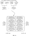
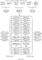
- FIG. 14 is a schematic flowchart of a data interleaving method according to another aspect of this application from the perspective of device interaction.
- the method 1400 shown in FIG. 14 includes the following steps.
- a network device generates interleaving indication information, where the interleaving indication information is used to indicate a size of an interleaving unit, and the interleaving unit is a time-frequency resource element group or a modulation symbol group.
- the interleaving unit is the time-frequency resource element group
- modulation symbols carried on one interleaving unit namely, one time-frequency resource element group
- the interleaving unit is the modulation symbol group
- modulation symbols in one interleaving unit that is, one modulation symbol group
- the method may further include: before the network device generates the interleaving indication information, determining, by the network device, the size of the interleaving unit based on a transmission parameter, where the transmission parameter includes at least one of the following parameters: a scheduling bandwidth, a delay spread, and a moving speed of a terminal device.
- the network device sends the interleaving indication information.
- the network device may send the indication information by using radio resource control RRC signaling, a media access control control element MAC-CE, or downlink control information DCI.
- RRC signaling a radio resource control RRC signaling
- MAC-CE media access control control element
- DCI downlink control information
- the terminal device receives the interleaving indication information.
- the terminal device determines the size of the interleaving unit based on the indication information.
- the terminal device may determine the size of the interleaving unit.
- a transmit end device (which may be a network device or a terminal device) may perform interleaving processing on the to-be-sent modulation symbol sequence by using the interleaving unit, and send modulation symbols on which interleaving processing is performed.
- a receive end device may perform de-interleaving processing on the modulation symbols based on the interleaving unit, to obtain the modulation symbol sequence.
- an interleaving process refers to the foregoing description for the interleaving method in the method in FIG. 4 to FIG. 13B . To avoid repetition, details are not described herein again.
- the interleaving process in this aspect of this application refer to an interleaving process in the prior art. This aspect of this application is not limited thereto.
- the network device may flexibly determine, based on the transmission parameter, a size of the time-frequency resource group that corresponds to the transmission parameter, and can determine different sizes of the time-frequency resource group based on different values of the parameter, to meet interleaving requirements in different scenarios, and a prior-art problem of high complexity caused by interleaving performed by using a CB as a unit can be resolved.
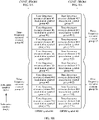
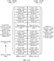
- FIG. 15 is a schematic flowchart of a data interleaving method according to another aspect of this application from the perspective of device interaction.
- the method 1500 shown in FIG. 15 includes the following steps.
- a transmit end device performs interleaving processing on a to-be-sent modulation symbol sequence by using an interleaving unit, to obtain an interleaving result, where a size of the interleaving unit is agreed on in a protocol or is determined based on a transmission parameter, and the interleaving unit is a time-frequency resource element group or a modulation symbol group.
- the transmit end device sends the modulation symbol sequence based on the interleaving result.
- the receive end device performs de-interleaving process on received modulation symbols by using the interleaving unit, to obtain the modulation symbol sequence.
- a size of the time-frequency resource element group may be agreed on in the protocol.
- the size of the interleaving unit is agreed on in the protocol.
- the transmit end device may perform interleaving processing based on the interleaving unit specified in the protocol, unlike the prior art in which a CB size is determined through calculation and then interleaving is performed.
- a receive end may also directly perform de-interleaving processing based on the interleaving unit specified in the protocol. Therefore, in this aspect of this application, interleaving complexity can be reduced, and system performance can be improved.
- the size of the time-frequency resource element group may be agreed on in the protocol.
- the size of the interleaving unit is agreed on in the protocol.
- the transmit end device may perform interleaving processing based on the interleaving unit specified in the protocol, unlike the prior art in which a CB size is determined through calculation and then interleaving is performed.
- a receive end may also directly perform de-interleaving processing based on the interleaving unit specified in the protocol. Therefore, in this aspect of this application, interleaving complexity can be reduced, and system performance can be improved.
- Both the transmit end device and the receive end device pre-store a correspondence between a plurality of values of the transmission parameter and a plurality of sizes of the time-frequency resource element group. For example, if the transmission parameter is a bandwidth, the correspondence may be shown in Table 1.
- the transmit end device and the receive end device may determine, based on the preset correspondence, a size of the time-frequency resource element group that corresponds to a current transmission parameter. For example, when the transmission parameter is a scheduling bandwidth, a transmit end and a receive end may determine, by looking up Table 1 based on a current value of the scheduling bandwidth, for example, a second scheduling bandwidth, that the size of the time-frequency resource group is a second size of the time-frequency resource group.
- the transmit end device and the receive end device may flexibly determine, based on the transmission parameter, the size of the time-frequency resource group that corresponds to the transmission parameter, and can determine different sizes of the time-frequency resource group based on different values of the parameter, to meet interleaving requirements in different scenarios, and a prior-art problem of high complexity caused by interleaving performed by using a CB as a unit can be resolved.
- FIG. 16 is a schematic structural diagram of a terminal device according to an aspect of this application.
- the terminal device is applicable to the system shown in FIG. 1 .
- FIG. 16 shows only main components of the terminal device.
- the terminal device 10 includes a processor, a memory, a control circuit, an antenna, and an input/output apparatus.
- the processor is mainly configured to: process a communication protocol and communication data, control the entire terminal device, execute a software program, and process data of the software program, for example, configured to support the terminal device in performing the actions described in the foregoing method embodiment, for example, performing interleaving processing on a modulation symbol sequence by using a time-frequency resource element group as an interleaving unit during uplink transmission, to obtain an order in which the modulation symbol sequence is mapped onto the plurality of time-frequency resource element groups, and sending the modulation symbol sequence in the order in which the modulation symbol sequence is mapped onto the plurality of time-frequency resource element groups; and performing de-interleaving processing on received modulation symbols by using the time-frequency resource element group as an interleaving unit when downlink data is received, to obtain the modulation symbol sequence.
- the memory is mainly configured to store the software program and data.
- the control circuit is mainly configured to perform conversion between a baseband signal and a radio frequency signal and process the radio frequency signal.
- the control circuit, together with the antenna, may also be referred to as a transceiver that is mainly configured to send and receive a radio frequency signal in an electromagnetic wave form.
- the input/output apparatus such as a touchscreen, a display, or a keyboard, is mainly configured to: receive data input by a user, and output data to the user.
- the processor may read a software program in a storage unit, explain and execute an instruction of the software program, and process data of the software program.
- the processor performs baseband processing on the to-be-sent data, and then outputs a baseband signal to a radio frequency circuit.
- the radio frequency circuit performs radio frequency processing on the baseband signal, and then sends a radio frequency signal in an electromagnetic wave form by using the antenna.
- the radio frequency circuit receives a radio frequency signal by using the antenna, converts the radio frequency signal into a baseband signal, and outputs the baseband signal to the processor.
- the processor converts the baseband signal into data, and processes the data.
- FIG. 16 shows only one memory and one processor.
- the terminal device may include a plurality of processors and a plurality of memories.
- the memory may also be referred to as a storage medium, a storage device, or the like. This is not limited in this aspect of this application.
- the processor may include a baseband processor and a central processing unit.
- the baseband processor is mainly configured to process the communication protocol and the communication data
- the central processing unit is mainly configured to: control the entire terminal device, execute the software program, and process the data of the software program.
- the processor in FIG. 16 may integrate functions of the baseband processor and the central processing unit.
- the baseband processor and the central processing unit may be independent processors, and interconnected by using a technology such as a bus.
- the terminal device may include a plurality of baseband processors to adapt to different network standards, the terminal device may include a plurality of central processing units to improve a processing capability of the terminal device, and components of the terminal device may be connected by using various buses.
- the baseband processor may also be expressed as a baseband processing circuit or a baseband processing chip.
- the central processing unit may also be expressed as a central processing circuit or a central processing chip.
- a function of processing the communication protocol and the communication data may be embedded into the processor, or may be stored in the storage unit in a form of the software program.
- the processor executes the software program to implement a baseband processing function.
- a control circuit and an antenna that has transmitting and receiving functions may be considered as a transceiver unit 101 of the terminal device 10, for example, configured to support the terminal device in performing the transmitting and receiving functions performed by the terminal device in the method embodiments shown in FIG. 1 to FIG. 15 .
- a processor having a processing function is considered as a processing unit 102 of the terminal device 10.
- the terminal device 10 includes the transceiver unit 101 and the processing unit 102.
- the transceiver unit may also be referred to as a transceiver, a transceiver, a transceiver apparatus, or the like.
- a device configured to implement a receiving function in the transceiver unit 101 may be considered as a receiving unit, and a device configured to implement the transmitting function in the transceiver unit 101 may be considered as a transmitting unit.
- the transceiver unit 101 includes the receiving unit and the transmitting unit.
- the receiving unit may also be referred to as a receiver, an input port, a receiver circuit, or the like.
- the transmitting unit may be referred to as a transmitter, a transmitter, a transmitter circuit, or the like.
- the processor 102 may be configured to execute an instruction stored in the memory, to control the transceiver unit 101 to receive a signal and/or send a signal, to complete a function of the terminal device in the foregoing method aspects.
- the function of the transceiver unit 101 is implemented by using a transceiver circuit or a transceiver-dedicated chip.
- FIG. 17 is a schematic structural diagram of a network device according to an aspect of this application, for example, may be a schematic structural diagram of a base station.
- the base station may be applied to the system shown in FIG. 1 , to perform a function of the network device in the foregoing method aspects.
- the base station 20 includes one or more radio frequency units such as remote radio units (remote radio unit, RRU) 201 and one or more baseband units (baseband unit, BBU) (which may also be referred to as digital units, digital unit, DU) 202.
- RRU remote radio unit
- BBU baseband unit
- the RRU 201 may be referred to as a transceiver unit, a transceiver, a transceiver circuit, a transceiver, or the like, and may include at least one antenna 2011 and radio frequency unit 2012.
- the RRU 201 is mainly configured to: send and receive a radio frequency signal, and perform conversion between the radio frequency signal and a baseband signal, for example, configured to send a modulation symbol to a terminal device.
- the BBU 202 is mainly configured to perform baseband processing, control the base station, and so on.
- the RRU 201 and the BBU 202 may be physically disposed together, or may be physically separated, namely, a distributed base station.
- the BBU 202 is a control center of the base station, or may be referred to as a processing unit, and is mainly configured to complete baseband processing functions such as channel coding, multiplexing, modulation, and spectrum spreading.
- the BBU (the processing unit) may be configured to control the base station to perform an operation procedure related to the network device in the foregoing method aspects.
- the BBU 202 may include one or more boards, and a plurality of boards may jointly support a radio access network (such as an LTE network) having single access standard, or may separately support radio access networks (for example, an LTE network, a 5G network, or another network) having different access standards.
- the BBU 202 further includes a memory 2021 and a processor 2022.
- the memory 2021 is configured to store a necessary instruction and data.
- the processor 2022 is configured to control the base station to perform a necessary action, for example, is configured to control the base station to perform the operation procedure related to the network device in the foregoing method aspects.
- the memory 2021 and the processor 2022 may serve the one or more boards. In other words, a memory and a processor may be independently disposed on each board. Alternatively, the plurality of boards may share a same memory and a same processor. In addition, a necessary circuit may be further disposed on each board.
- FIG. 18 is a schematic structural diagram of a communications apparatus 1800.
- the apparatus 1800 may be configured to implement the methods described in the foregoing method aspects. Refer to the descriptions in the foregoing method aspects.
- the communications apparatus 1800 may be a chip, a network device (for example, a base station), a terminal device, or the like.
- the communications apparatus 1800 includes one or more processors 1801.
- the processor 1801 may be a general purpose processor, a dedicated processor, or the like. It should be understood that when the processor 1801 is a dedicated processor, an instruction may not be required, and an integrated logic circuit of hardware in the processor completes the methods in the foregoing aspects.
- the processor may be an application-specific integrated circuit (ASIC) or the like.
- the processor 1801 may alternatively be, for example, a general purpose processor.
- the communications apparatus 1800 may include one or more memories 1802.
- the memory stores an instruction 1804, and the instruction may be run on the processor, so that the communications apparatus 1800 performs the methods described in the foregoing method aspects.
- the memory may further store data.
- the processor may further store an instruction and/or data.
- the processor and the memory may be disposed separately, or may be integrated together.
- the processor includes a central processing unit (central processing unit, CPU), a network processor (network processor, NP), a microprocessor, and the like.
- the processor may alternatively be a digital signal processor (DSP), a field programmable gate array (FPGA), another programmable logic device, a discrete gate or a transistor logic device, a discrete hardware component, any conventional processor, or the like.
- DSP digital signal processor
- FPGA field programmable gate array
- FPGA field programmable gate array
- This aspect of this application is not limited thereto.
- the processor 1801 may be a baseband processor or a central processing unit.
- the baseband processor may be configured to process a communication protocol and communication data
- the central processing unit may be configured to: control the communications apparatus (for example, the base station, the terminal, or the chip), execute a software program, and process data of the software program.
- the communications apparatus may include a transceiver unit, configured to input (receive) and output (send) a signal.
- the communications apparatus may be a chip, and the transceiver unit may be an input and/or output circuit or a communications interface of the chip.
- the chip may be used for a terminal, a base station, or another network device.
- the communications apparatus may be a terminal, a base station, or another network device, and the transceiver unit may be a transceiver, a radio frequency chip, or the like.
- the communications apparatus 1800 includes the one or more processors 1801.
- the one or more processors 1801 may implement the methods performed by the network device or the terminal device in the aspects shown in FIG. 1 and FIG. 15 .
- the communications apparatus 1800 includes a means (means) that obtains modulation symbols, a means (means) that is configured to perform interleaving processing on the modulation symbols, and a means (means) that is configured to send the interleaved modulation symbols.
- Functions of performing interleaving processing on the modulation symbols and sending the interleaved modulation symbols may be implemented by using the one or more processors.
- the modulation symbols may be obtained and interleaving processing may be performed on the modulation symbols.
- the interleaved modulation symbols are sent by using a transceiver, an input/output circuit, or an interface of a chip.
- the communications apparatus 1800 includes a means (means) configured to receive modulation symbols and a means (means) configured to de-interleave the modulation symbols.
- the modulation symbols may be received by using the transceiver, the input/output circuit, or the interface of the chip, and the modulation symbols are de-interleaved by using the one or more processors.
- the processor 1801 may further implement another function.
- the processor 1801 may be general purpose processor.
- the processor 1801 may include an instruction 1803.
- the instruction may be run on the processor, so that the communications apparatus 1800 performs the method described in the foregoing method aspects.
- the communications apparatus 1800 may further include a circuit.
- the circuit may implement a function in the foregoing method embodiments.
- the communications apparatus 1800 may further include a transceiver unit 1805 and an antenna 1806.
- the processor 1801 may be referred to as a processing unit, and controls the communications apparatus (the terminal device or the network device).
- the transceiver unit 1805 may be referred to as a transceiver, a transceiver circuit, a transceiver, or the like, and is configured to implement a transmitting and receiving function of the communications apparatus by using the antenna 1806.
- An aspect of this application further provides a communications system, including the foregoing network device and terminal device.
- the processor may be a CPU, or may be another general purpose processor, a digital signal processor (DSP), an application-specific integrated circuit (ASIC), a field programmable gate array (FPGA) or another programmable logic device, a discrete gate or transistor logic device, a discrete hardware component, or the like.
- DSP digital signal processor
- ASIC application-specific integrated circuit
- FPGA field programmable gate array
- the general purpose processor may be a microprocessor, or the processor may be any conventional processor or the like.
- a memory may include a read-only memory and a random access memory, and provide an instruction and data to the processor.
- a part of the memory may further include a non-volatile random access memory.
- a bus system may further include a power bus, a control bus, a status signal bus, and the like, in addition to a data bus.
- a power bus may further include a power bus, a control bus, a status signal bus, and the like, in addition to a data bus.
- various types of buses in the figure are marked as the bus system.
- steps in the foregoing methods can be implemented by using an integrated logical circuit of hardware in the processor, or by using instructions in a form of software.
- the steps of the method disclosed with reference to the aspects of this application may be directly performed by a hardware processor, or may be performed by using a combination of the hardware in the processor and a software module.
- the software module may be located in a mature storage medium in the art, for example, a random access memory, a flash memory, a read-only memory, a programmable read-only memory, an electrically erasable programmable memory, or a register.
- the storage medium is located in the memory, and the processor reads information in the memory and completes the steps in the foregoing methods in combination with hardware of the processor. To avoid repetition, details are not described herein again.
- a and/or B may represent the following three cases: Only A exists, both A and B exist, and only B exists.
- sequence numbers of the foregoing processes do not mean execution sequences in various aspects of this application.
- the execution sequences of the processes should be determined according to functions and internal logic of the processes, and should not be construed as any limitation on the implementation processes of the aspects of this application.
- the disclosed system, apparatus, and method may be implemented in other manners.
- the described apparatus aspect is merely an example.
- the unit division is merely logical function division and may be other division in actual implementation.
- a plurality of units or components may be combined or integrated into another system, or some features may be ignored or not performed.
- the displayed or discussed mutual couplings or direct couplings or communication connections may be implemented by using some interfaces.
- the indirect couplings or communication connections between the apparatuses or units may be implemented in electronic, mechanical, or other forms.
- the units described as separate parts may or may not be physically separate, and parts displayed as units may or may not be physical units, may be located in one position, or may be distributed on a plurality of network units. Some or all of the units may be selected based on actual requirements to achieve the objectives of the solutions of the aspects.
- the aspects may be implemented by using software, hardware, firmware, or any combination thereof.
- the aspects may be implemented completely or partially in a form of a computer program product.
- the computer program product includes one or more computer instructions (programs).
- programs When the computer program instructions (programs) are loaded and executed on a computer, the procedure or functions according to the aspects of this application are all or partially generated.
- the computer may be a general-purpose computer, a dedicated computer, a computer network, or other programmable apparatuses.
- the computer instructions may be stored in a computer-readable storage medium or may be transmitted from a computer-readable storage medium to another computer-readable storage medium.
- the computer instructions may be transmitted from a website, computer, server, or data center to another website, computer, server, or data center in a wired (for example, a coaxial cable, an optical fiber, or a digital subscriber line (DSL)) or wireless (for example, infrared, radio, or microwave) manner.
- the computer-readable storage medium may be any usable medium accessible by a computer, or a data storage device, such as a server or a data center, integrating one or more usable media.
- the usable medium may be a magnetic medium (for example, a floppy disk, a hard disk, or a magnetic tape), an optical medium (for example, a DVD), a semiconductor medium (for example, a solid-state drive solid state disk (SSD)), or the like.
- a magnetic medium for example, a floppy disk, a hard disk, or a magnetic tape
- an optical medium for example, a DVD
- a semiconductor medium for example, a solid-state drive solid state disk (SSD)
Landscapes
- Engineering & Computer Science (AREA)
- Signal Processing (AREA)
- Computer Networks & Wireless Communication (AREA)
- Mobile Radio Communication Systems (AREA)
- Detection And Prevention Of Errors In Transmission (AREA)
Claims (4)
- Datenübertragungsverfahren, das Folgendes umfasst:Erhalten (410), durch eine Übertragungsendvorrichtung, einer zu übertragenden Modulationssymbolsequenz in mehreren Zeit-Frequenz-Ressourcenelementgruppen, wobei die Zeit-Frequenz-Ressourcenelementgruppe N Zeit-Frequenz-Ressourcenelemente umfasst, N eine ganze Zahl größer als oder gleich 2 ist, das Zeit-Frequenz-Ressourcenelement wenigstens ein Ressourcenelement (RE) umfasst, ein Zeit-Frequenz-Ressourcenelement verwendet wird, um eine Modulationssymbolgruppe zu tragen, eine Modulationssymbolgruppe wenigstens ein Modulationssymbol umfasst, und eine Größe der Zeit-Frequenz-Ressourcenelementgruppe in einem Protokoll vereinbart wird, oder eine Größe der Zeit-Frequenz-Ressourcenelementgruppe basierend auf einem Übertragungsparameter bestimmt wird;Durchführen (420), durch die Übertragungsendvorrichtung, einer Verschachtelungsverarbeitung an der Modulationssymbolsequenz durch Verwenden der Zeit-Frequenz-Ressourcenelementgruppe als eine Verschachtelungseinheit, um eine Reihenfolge zu erhalten, in der die Modulationssymbolsequenz auf die mehreren Zeit-Frequenz-Ressourcenelementgruppen abgebildet wird, wobei mehrere aufeinanderfolgende Modulationssymbolgruppen in der Modulationssymbolsequenz auf wenigstens zwei der mehreren Zeit-Frequenz-Ressourcenelementgruppen abgebildet werden; undSenden (430), durch die Übertragungsendvorrichtung, der Modulationssymbolsequenz in der Reihenfolge, in der die Modulationssymbolsequenz auf die mehreren Zeit-Frequenz-Ressourcenelementgruppen abgebildet wird, wobeidie Modulationssymbolsequenz eine erste Modulationssymbolsequenz und eine zweite Modulationssymbolsequenz umfasst, die mehreren Zeit-Frequenz-Ressourcenelementgruppen einen ersten Zeit-Frequenz-Ressourcenelementgruppensatz und einen zweiten Zeit-Frequenz-Ressourcenelementgruppensatz umfassen, der erste Zeit-Frequenz-Ressourcenelementgruppensatz verwendet wird, um die erste Modulationssymbolsequenz zu tragen, der zweite Zeit-Frequenz-Ressourcenelementgruppensatz verwendet wird, um die zweite Modulationssymbolsequenz zu tragen, der erste Zeit-Frequenz-Ressourcenelementgruppensatz wenigstens zwei erste Zeit-Frequenz-Ressourcenelementgruppen umfasst, die erste Zeit-Frequenz-Ressourcenelementgruppe N1 erste Zeit-Frequenz-Ressourcenelemente umfasst, N1 eine ganze Zahl größer als oder gleich 2 ist, die zweite Zeit-Frequenz-Ressourcenelementgruppe wenigstens zwei zweite Zeit-Frequenz-Ressourcenelementgruppen umfasst, die zweite Zeit-Frequenz-Ressourcenelementgruppe N2 zweite Zeit-Frequenz-Ressourcenelemente umfasst, N2 eine ganze Zahl größer als oder gleich 2 ist, ein erstes Zeit-Frequenz-Ressourcenelement verwendet wird, um eine erste Modulationssymbolgruppe zu tragen, und ein zweites Zeit-Frequenz-Ressourcenelement verwendet wird, um eine zweite Modulationssymbolgruppe zu tragen, wobei eine Anzahl von Ressourcenelementen (REs), die in dem ersten Zeit-Frequenz-Ressourcenelement enthalten sind, sich von der von Ressourcenelementen (REs) unterscheidet, die in dem zweiten Zeit-Frequenz-Ressourcenelement enthalten sind; unddas Durchführen, durch die Übertragungsendvorrichtung, der Verschachtelungsverarbeitung an der Modulationssymbolsequenz durch Verwenden der Zeit-Frequenz-Ressourcenelementgruppe als eine Verschachtelungseinheit, um eine Reihenfolge zu erhalten, in der die Modulationssymbolsequenz auf die mehreren Zeit-Frequenz-Ressourcenelementgruppen abgebildet wird, Folgendes umfasst:
Durchführen, durch die Übertragungsendvorrichtung, der Verschachtelungsverarbeitung an der ersten Modulationssymbolsequenz durch Verwenden der ersten Zeit-Frequenz-Ressourcenelementgruppe als eine Verschachtelungseinheit und Durchführen der Verschachtelungsverarbeitung an der zweiten Modulationssymbolsequenz durch Verwenden der zweiten Zeit-Frequenz-Ressourcenelementgruppe als eine Verschachtelungseinheit, um eine erste Reihenfolge, in der die erste Modulationssymbolsequenz auf den ersten Zeit-Frequenz-Ressourcenelementgruppensatz abgebildet wird, und eine zweite Reihenfolge zu erhalten, in der die zweite Modulationssymbolsequenz auf die zweite Zeit-Frequenz-Ressourcenelementgruppe abgebildet wird, wobei mehrere aufeinanderfolgende erste Modulationssymbolgruppen in der ersten Modulationssymbolsequenz auf die wenigstens zwei ersten Zeit-Frequenz-Ressourcenelementgruppen in dem ersten Zeit-Frequenz-Ressourcenelementgruppensatz abgebildet werden und mehrere aufeinanderfolgende zweite Modulationssymbolgruppen in der zweiten Modulationssymbolsequenz auf die wenigstens zwei zweiten Zeit-Frequenz-Ressourcenelementgruppen in dem zweiten Zeit-Frequenz-Ressourcenelementgruppensatz abgebildet werden. - Übertragungsendvorrichtung, die Folgendes umfasst:eine Verarbeitungseinheit, die für Folgendes konfiguriert ist: Erhalten einer zu übertragenden Modulationssymbolsequenz in mehreren Zeit-Frequenz-Ressourcenelementgruppen, wobei die Zeit-Frequenz-Ressourcenelementgruppe N Zeit-Frequenz-Ressourcenelemente umfasst, N eine ganze Zahl größer als oder gleich 2 ist, das Zeit-Frequenz-Ressourcenelement wenigstens ein Ressourcenelement (RE) umfasst, ein Zeit-Frequenz-Ressourcenelement verwendet wird, um eine Modulationssymbolgruppe zu tragen, eine Modulationssymbolgruppe wenigstens ein Modulationssymbol umfasst, und eine Größe der Zeit-Frequenz-Ressourcenelementgruppe in einem Protokoll vereinbart wird, oder eine Größe der Zeit-Frequenz-Ressourcenelementgruppe basierend auf einem Übertragungsparameter bestimmt wird; undDurchführen der Verschachtelungsverarbeitung der Modulationssymbolsequenz durch Verwenden der Zeit-Frequenz-Ressourcenelementgruppe als eine Verschachtelungseinheit, um eine Reihenfolge zu erhalten, in der die Modulationssymbolsequenz auf die mehreren Zeit-Frequenz-Ressourcenelementgruppen abgebildet wird, wobei mehrere aufeinanderfolgende Modulationssymbolgruppen in der Modulationssymbolsequenz auf wenigstens zwei der mehreren Zeit-Frequenz-Ressourcenelementgruppen abgebildet werden; undeine Transceivereinheit, die konfiguriert ist, um die Modulationssymbolsequenz in der Reihenfolge zu senden, in der die Modulationssymbolsequenz auf die mehreren Zeit-Frequenz-Ressourcenelementgruppen abgebildet wird, wobeidie Modulationssymbolsequenz eine erste Modulationssymbolsequenz und eine zweite Modulationssymbolsequenz umfasst, die mehreren Zeit-Frequenz-Ressourcenelementgruppen einen ersten Zeit-Frequenz-Ressourcenelementgruppensatz und einen zweiten Zeit-Frequenz-Ressourcenelementgruppensatz umfassen, der erste Zeit-Frequenz-Ressourcenelementgruppensatz verwendet wird, um die erste Modulationssymbolsequenz zu tragen, der zweite Zeit-Frequenz-Ressourcenelementgruppensatz verwendet wird, um die zweite Modulationssymbolsequenz zu tragen, der erste Zeit-Frequenz-Ressourcenelementgruppensatz wenigstens zwei erste Zeit-Frequenz-Ressourcenelementgruppen umfasst, die erste Zeit-Frequenz-Ressourcenelementgruppe N1 erste Zeit-Frequenz-Ressourcenelemente umfasst, N1 eine ganze Zahl größer als oder gleich 2 ist, die zweite Zeit-Frequenz-Ressourcenelementgruppe wenigstens zwei zweite Zeit-Frequenz-Ressourcenelementgruppen umfasst, die zweite Zeit-Frequenz-Ressourcenelementgruppe N2 zweite Zeit-Frequenz-Ressourcenelemente umfasst, N2 eine ganze Zahl größer als oder gleich 2 ist, ein erstes Zeit-Frequenz-Ressourcenelement verwendet wird, um eine erste Modulationssymbolgruppe zu tragen, und ein zweites Zeit-Frequenz-Ressourcenelement verwendet wird, um eine zweite Modulationssymbolgruppe zu tragen, wobei eine Anzahl von Ressourcenelementen (REs), die in dem ersten Zeit-Frequenz-Ressourcenelement enthalten sind, sich von der von Ressourcenelementen (REs) unterscheidet, die in dem zweiten Zeit-Frequenz-Ressourcenelement enthalten sind, wobeidie Verarbeitungseinheit speziell für Folgendes konfiguriert ist: Durchführen der Verschachtelungsverarbeitung an der ersten Modulationssymbolsequenz durch Verwenden der ersten Zeit-Frequenz-Ressourcenelementgruppe als eine Verschachtelungseinheit und Durchführen der Verschachtelungsverarbeitung an der zweiten Modulationssymbolsequenz durch Verwenden der zweiten Zeit-Frequenz-Ressourcenelementgruppe als eine Verschachtelungseinheit, um eine erste Reihenfolge, in der die erste Modulationssymbolsequenz auf den ersten Zeit-Frequenz-Ressourcenelementgruppensatz abgebildet wird, und eine zweite Reihenfolge zu erhalten, in der die zweite Modulationssymbolsequenz auf die zweite Zeit-Frequenz-Ressourcenelementgruppe abgebildet wird, wobei mehrere aufeinanderfolgende erste Modulationssymbolgruppen in der ersten Modulationssymbolsequenz auf die wenigstens zwei ersten Zeit-Frequenz-Ressourcenelementgruppen in dem ersten Zeit-Frequenz-Ressourcenelementgruppensatz abgebildet werden und mehrere aufeinanderfolgende zweite Modulationssymbolgruppen in der zweiten Modulationssymbolsequenz auf die wenigstens zwei zweiten Zeit-Frequenz-Ressourcenelementgruppen in dem zweiten Zeit-Frequenz-Ressourcenelementgruppensatz abgebildet werden.
- Computerlesbares Speichermedium, das ein Computerprogramm umfasst, wobei, wenn das Computerprogramm auf der Übertragungsendvorrichtung nach Anspruch 2 abläuft, die Übertragungsendvorrichtung veranlasst wird, das Verfahren nach Anspruch 1 durchzuführen.
- Computerprogrammprodukt, wobei, wenn das Computerprogrammprodukt durch die Übertragungsendvorrichtung nach Anspruch 2 ausgeführt wird, die Übertragungsendvorrichtung veranlasst wird, das Verfahren nach Anspruch 1 zu implementieren.
Applications Claiming Priority (2)
| Application Number | Priority Date | Filing Date | Title |
|---|---|---|---|
| CN201710841935.6A CN109525359B (zh) | 2017-09-18 | 2017-09-18 | 数据传输的方法和设备 |
| PCT/CN2018/104205 WO2019052388A1 (zh) | 2017-09-18 | 2018-09-05 | 数据传输的方法和设备 |
Publications (3)
| Publication Number | Publication Date |
|---|---|
| EP3664550A1 EP3664550A1 (de) | 2020-06-10 |
| EP3664550A4 EP3664550A4 (de) | 2020-09-09 |
| EP3664550B1 true EP3664550B1 (de) | 2022-08-24 |
Family
ID=65722427
Family Applications (1)
| Application Number | Title | Priority Date | Filing Date |
|---|---|---|---|
| EP18855840.7A Active EP3664550B1 (de) | 2017-09-18 | 2018-09-05 | Datenübertragungsverfahren und -vorrichtung |
Country Status (4)
| Country | Link |
|---|---|
| US (1) | US11251997B2 (de) |
| EP (1) | EP3664550B1 (de) |
| CN (1) | CN109525359B (de) |
| WO (1) | WO2019052388A1 (de) |
Families Citing this family (16)
| Publication number | Priority date | Publication date | Assignee | Title |
|---|---|---|---|---|
| CN109219149B (zh) * | 2017-07-08 | 2020-05-22 | 上海朗帛通信技术有限公司 | 一种被用于动态调度的用户设备、基站中的方法和装置 |
| CN111769899B (zh) * | 2019-03-30 | 2021-10-01 | 华为技术有限公司 | 确定传输资源的方法及装置 |
| US20200351070A1 (en) * | 2019-05-02 | 2020-11-05 | Mediatek Singapore Pte. Ltd. | Low papr computer generated sequence pairing |
| WO2020101742A1 (en) | 2019-06-03 | 2020-05-22 | Futurewei Technologies, Inc. | Transmitting signals using optical lens as a beamformer |
| WO2020163881A2 (en) * | 2019-06-03 | 2020-08-13 | Futurewei Technologies, Inc. | Apparatus and methods for receiving signals using optical lens as a beamformer |
| WO2021248428A1 (en) * | 2020-06-12 | 2021-12-16 | Qualcomm Incorporated | Time domain interleaving for physical shared channel communications |
| WO2022141326A1 (zh) * | 2020-12-30 | 2022-07-07 | 华为技术有限公司 | 交织、解交织方法及装置 |
| CN115277340B (zh) * | 2021-04-30 | 2024-04-19 | 维沃移动通信有限公司 | 数据传输方法、装置、设备及存储介质 |
| WO2023165776A1 (en) * | 2022-03-02 | 2023-09-07 | Nokia Technologies Oy | Timing error correction in positioning of terminal device |
| CN117318879A (zh) * | 2022-06-22 | 2023-12-29 | 大唐移动通信设备有限公司 | 数据传输方法、设备、装置及存储介质 |
| CN119011102A (zh) * | 2023-05-22 | 2024-11-22 | 维沃软件技术有限公司 | 信号传输方法、装置、信号发送设备及信号接收设备 |
| CN119496563A (zh) * | 2023-08-15 | 2025-02-21 | 华为技术有限公司 | 一种信号处理方法及相关装置 |
| CN121548962A (zh) * | 2023-09-26 | 2026-02-17 | 华为技术有限公司 | 一种信息处理方法及装置 |
| CN119945615A (zh) * | 2023-11-01 | 2025-05-06 | 大唐移动通信设备有限公司 | 数据传输方法、装置、终端、网络设备和存储介质 |
| WO2025138141A1 (zh) * | 2023-12-29 | 2025-07-03 | Oppo广东移动通信有限公司 | 无线通信的方法及通信设备 |
| CN120454928A (zh) * | 2024-02-08 | 2025-08-08 | 华为技术有限公司 | 一种通信方法及通信装置 |
Family Cites Families (13)
| Publication number | Priority date | Publication date | Assignee | Title |
|---|---|---|---|---|
| BRPI0810979A2 (pt) * | 2007-04-27 | 2015-07-21 | Lg Electronics Inc | Método para transmissão de canal de controle em sistema de comunicação móvel |
| CN101330487B (zh) * | 2007-06-19 | 2012-04-04 | 华为技术有限公司 | 一种符号交织方法、装置及终端设备 |
| CN102082600A (zh) * | 2009-12-01 | 2011-06-01 | 中兴通讯股份有限公司 | 中继链路下行控制信息配置方法及传输基站、中继站与方法 |
| CN102904665A (zh) * | 2011-07-25 | 2013-01-30 | 华为技术有限公司 | 一种控制信道的传输方法、装置和系统 |
| US20130294318A1 (en) * | 2012-05-03 | 2013-11-07 | Qualcomm Incorporated | Efficient update of tmgi list in lte embms |
| WO2013183975A1 (ko) * | 2012-06-08 | 2013-12-12 | 엘지전자 주식회사 | 무선통신 시스템에서 상향링크 제어 신호 전송 방법 및 장치 |
| CN103580834B (zh) * | 2012-07-31 | 2018-06-22 | 中兴通讯股份有限公司 | ePDCCH发送、接收方法及装置、基站、用户设备 |
| US9832001B2 (en) * | 2013-06-21 | 2017-11-28 | Sharp Kabushiki Kaisha | Terminal device, base station, communication system, and communication method |
| US11743897B2 (en) * | 2013-12-20 | 2023-08-29 | Qualcomm Incorporated | Techniques for configuring uplink channels in unlicensed radio frequency spectrum bands |
| CN105656596B (zh) * | 2014-11-14 | 2019-07-19 | 电信科学技术研究院 | 一种进行数据传输的方法和设备 |
| CN105812107B (zh) | 2014-12-31 | 2019-12-06 | 中兴通讯股份有限公司 | Ofdma系统中数据包处理方法及装置 |
| WO2017135799A1 (en) * | 2016-02-05 | 2017-08-10 | Samsung Electronics Co., Ltd. | Multiple access method, and corresponding transmission method, receiver and transmitter |
| KR20250026384A (ko) * | 2017-06-16 | 2025-02-25 | 주식회사 윌러스표준기술연구소 | 무선 통신 시스템에서 데이터 채널 및 제어 채널의 송수신 방법, 장치, 및 시스템 |
-
2017
- 2017-09-18 CN CN201710841935.6A patent/CN109525359B/zh active Active
-
2018
- 2018-09-05 EP EP18855840.7A patent/EP3664550B1/de active Active
- 2018-09-05 WO PCT/CN2018/104205 patent/WO2019052388A1/zh not_active Ceased
-
2020
- 2020-03-18 US US16/822,781 patent/US11251997B2/en active Active
Also Published As
| Publication number | Publication date |
|---|---|
| US11251997B2 (en) | 2022-02-15 |
| EP3664550A4 (de) | 2020-09-09 |
| WO2019052388A1 (zh) | 2019-03-21 |
| CN109525359B (zh) | 2022-03-11 |
| EP3664550A1 (de) | 2020-06-10 |
| CN109525359A (zh) | 2019-03-26 |
| US20200220752A1 (en) | 2020-07-09 |
Similar Documents
| Publication | Publication Date | Title |
|---|---|---|
| EP3664550B1 (de) | Datenübertragungsverfahren und -vorrichtung | |
| KR102153971B1 (ko) | 크로스 캐리어 스케줄링을 위한 물리 하향링크 제어 채널들의 제어 채널 요소들의 획득 | |
| US12376125B2 (en) | Communication method and communication apparatus | |
| US10938531B2 (en) | Data transmission method, network device, and terminal device | |
| KR102445177B1 (ko) | 다운링크 제어 정보(dci)의 전송 방법, 장치 및 네트워크 기기 | |
| EP3606242B1 (de) | Datenübertragungsverfahren und -vorrichtung | |
| CN110574433B (zh) | 在无线网络上发送测量报告的方法和装置 | |
| US11962526B2 (en) | Method for obtaining quantity of resource elements in communication process and related apparatus | |
| CN106464626B (zh) | 一种基带单元bbu与远端射频单元rru之间的数据传输方法和装置 | |
| CN108632011B (zh) | 用于进行数据传输的方法和装置 | |
| US20180352545A1 (en) | User terminal, radio base station and radio communication method | |
| CN108632009A (zh) | 无线通信的方法和装置 | |
| KR20170101914A (ko) | 정보 송신 방법, 장치 및 기기 | |
| CN111435892B (zh) | 接收数据的方法和装置 | |
| CN119422415A (zh) | 发信号通知参考音调与数据音调之间的功率偏移 | |
| US20250358049A1 (en) | Data transmission method, device and apparatus, and storage medium | |
| US12580680B2 (en) | Interleaver design for noncoherent reed muller codes | |
| US20250240121A1 (en) | Code block bundle-based interleaving for frequency diversity | |
| WO2025049037A1 (en) | Resource allocation indication in unrestricted bandwidth part | |
| CN118339789A (zh) | 关于概率整形的指示 | |
| WO2016170477A1 (en) | Providing information regarding transport formats based on aclr and/or evm and related methods and communication nodes |
Legal Events
| Date | Code | Title | Description |
|---|---|---|---|
| STAA | Information on the status of an ep patent application or granted ep patent |
Free format text: STATUS: THE INTERNATIONAL PUBLICATION HAS BEEN MADE |
|
| PUAI | Public reference made under article 153(3) epc to a published international application that has entered the european phase |
Free format text: ORIGINAL CODE: 0009012 |
|
| STAA | Information on the status of an ep patent application or granted ep patent |
Free format text: STATUS: REQUEST FOR EXAMINATION WAS MADE |
|
| 17P | Request for examination filed |
Effective date: 20200306 |
|
| AK | Designated contracting states |
Kind code of ref document: A1 Designated state(s): AL AT BE BG CH CY CZ DE DK EE ES FI FR GB GR HR HU IE IS IT LI LT LU LV MC MK MT NL NO PL PT RO RS SE SI SK SM TR |
|
| AX | Request for extension of the european patent |
Extension state: BA ME |
|
| A4 | Supplementary search report drawn up and despatched |
Effective date: 20200812 |
|
| RIC1 | Information provided on ipc code assigned before grant |
Ipc: H04L 1/00 20060101ALI20200806BHEP Ipc: H04W 72/04 20090101AFI20200806BHEP |
|
| DAV | Request for validation of the european patent (deleted) | ||
| DAX | Request for extension of the european patent (deleted) | ||
| GRAP | Despatch of communication of intention to grant a patent |
Free format text: ORIGINAL CODE: EPIDOSNIGR1 |
|
| STAA | Information on the status of an ep patent application or granted ep patent |
Free format text: STATUS: GRANT OF PATENT IS INTENDED |
|
| INTG | Intention to grant announced |
Effective date: 20220408 |
|
| GRAS | Grant fee paid |
Free format text: ORIGINAL CODE: EPIDOSNIGR3 |
|
| GRAA | (expected) grant |
Free format text: ORIGINAL CODE: 0009210 |
|
| STAA | Information on the status of an ep patent application or granted ep patent |
Free format text: STATUS: THE PATENT HAS BEEN GRANTED |
|
| AK | Designated contracting states |
Kind code of ref document: B1 Designated state(s): AL AT BE BG CH CY CZ DE DK EE ES FI FR GB GR HR HU IE IS IT LI LT LU LV MC MK MT NL NO PL PT RO RS SE SI SK SM TR |
|
| REG | Reference to a national code |
Ref country code: CH Ref legal event code: EP |
|
| REG | Reference to a national code |
Ref country code: DE Ref legal event code: R096 Ref document number: 602018039824 Country of ref document: DE |
|
| REG | Reference to a national code |
Ref country code: IE Ref legal event code: FG4D |
|
| REG | Reference to a national code |
Ref country code: AT Ref legal event code: REF Ref document number: 1514570 Country of ref document: AT Kind code of ref document: T Effective date: 20220915 |
|
| REG | Reference to a national code |
Ref country code: LT Ref legal event code: MG9D |
|
| REG | Reference to a national code |
Ref country code: NL Ref legal event code: MP Effective date: 20220824 |
|
| PG25 | Lapsed in a contracting state [announced via postgrant information from national office to epo] |
Ref country code: SE Free format text: LAPSE BECAUSE OF FAILURE TO SUBMIT A TRANSLATION OF THE DESCRIPTION OR TO PAY THE FEE WITHIN THE PRESCRIBED TIME-LIMIT Effective date: 20220824 Ref country code: RS Free format text: LAPSE BECAUSE OF FAILURE TO SUBMIT A TRANSLATION OF THE DESCRIPTION OR TO PAY THE FEE WITHIN THE PRESCRIBED TIME-LIMIT Effective date: 20220824 Ref country code: PT Free format text: LAPSE BECAUSE OF FAILURE TO SUBMIT A TRANSLATION OF THE DESCRIPTION OR TO PAY THE FEE WITHIN THE PRESCRIBED TIME-LIMIT Effective date: 20221226 Ref country code: NO Free format text: LAPSE BECAUSE OF FAILURE TO SUBMIT A TRANSLATION OF THE DESCRIPTION OR TO PAY THE FEE WITHIN THE PRESCRIBED TIME-LIMIT Effective date: 20221124 Ref country code: NL Free format text: LAPSE BECAUSE OF FAILURE TO SUBMIT A TRANSLATION OF THE DESCRIPTION OR TO PAY THE FEE WITHIN THE PRESCRIBED TIME-LIMIT Effective date: 20220824 Ref country code: LV Free format text: LAPSE BECAUSE OF FAILURE TO SUBMIT A TRANSLATION OF THE DESCRIPTION OR TO PAY THE FEE WITHIN THE PRESCRIBED TIME-LIMIT Effective date: 20220824 Ref country code: LT Free format text: LAPSE BECAUSE OF FAILURE TO SUBMIT A TRANSLATION OF THE DESCRIPTION OR TO PAY THE FEE WITHIN THE PRESCRIBED TIME-LIMIT Effective date: 20220824 Ref country code: FI Free format text: LAPSE BECAUSE OF FAILURE TO SUBMIT A TRANSLATION OF THE DESCRIPTION OR TO PAY THE FEE WITHIN THE PRESCRIBED TIME-LIMIT Effective date: 20220824 |
|
| REG | Reference to a national code |
Ref country code: AT Ref legal event code: MK05 Ref document number: 1514570 Country of ref document: AT Kind code of ref document: T Effective date: 20220824 |
|
| PG25 | Lapsed in a contracting state [announced via postgrant information from national office to epo] |
Ref country code: PL Free format text: LAPSE BECAUSE OF FAILURE TO SUBMIT A TRANSLATION OF THE DESCRIPTION OR TO PAY THE FEE WITHIN THE PRESCRIBED TIME-LIMIT Effective date: 20220824 Ref country code: IS Free format text: LAPSE BECAUSE OF FAILURE TO SUBMIT A TRANSLATION OF THE DESCRIPTION OR TO PAY THE FEE WITHIN THE PRESCRIBED TIME-LIMIT Effective date: 20221224 Ref country code: HR Free format text: LAPSE BECAUSE OF FAILURE TO SUBMIT A TRANSLATION OF THE DESCRIPTION OR TO PAY THE FEE WITHIN THE PRESCRIBED TIME-LIMIT Effective date: 20220824 Ref country code: GR Free format text: LAPSE BECAUSE OF FAILURE TO SUBMIT A TRANSLATION OF THE DESCRIPTION OR TO PAY THE FEE WITHIN THE PRESCRIBED TIME-LIMIT Effective date: 20221125 |
|
| REG | Reference to a national code |
Ref country code: DE Ref legal event code: R119 Ref document number: 602018039824 Country of ref document: DE |
|
| PG25 | Lapsed in a contracting state [announced via postgrant information from national office to epo] |
Ref country code: SM Free format text: LAPSE BECAUSE OF FAILURE TO SUBMIT A TRANSLATION OF THE DESCRIPTION OR TO PAY THE FEE WITHIN THE PRESCRIBED TIME-LIMIT Effective date: 20220824 Ref country code: RO Free format text: LAPSE BECAUSE OF FAILURE TO SUBMIT A TRANSLATION OF THE DESCRIPTION OR TO PAY THE FEE WITHIN THE PRESCRIBED TIME-LIMIT Effective date: 20220824 Ref country code: ES Free format text: LAPSE BECAUSE OF FAILURE TO SUBMIT A TRANSLATION OF THE DESCRIPTION OR TO PAY THE FEE WITHIN THE PRESCRIBED TIME-LIMIT Effective date: 20220824 Ref country code: DK Free format text: LAPSE BECAUSE OF FAILURE TO SUBMIT A TRANSLATION OF THE DESCRIPTION OR TO PAY THE FEE WITHIN THE PRESCRIBED TIME-LIMIT Effective date: 20220824 Ref country code: CZ Free format text: LAPSE BECAUSE OF FAILURE TO SUBMIT A TRANSLATION OF THE DESCRIPTION OR TO PAY THE FEE WITHIN THE PRESCRIBED TIME-LIMIT Effective date: 20220824 Ref country code: AT Free format text: LAPSE BECAUSE OF FAILURE TO SUBMIT A TRANSLATION OF THE DESCRIPTION OR TO PAY THE FEE WITHIN THE PRESCRIBED TIME-LIMIT Effective date: 20220824 |
|
| REG | Reference to a national code |
Ref country code: CH Ref legal event code: PL |
|
| REG | Reference to a national code |
Ref country code: BE Ref legal event code: MM Effective date: 20220930 |
|
| PG25 | Lapsed in a contracting state [announced via postgrant information from national office to epo] |
Ref country code: SK Free format text: LAPSE BECAUSE OF FAILURE TO SUBMIT A TRANSLATION OF THE DESCRIPTION OR TO PAY THE FEE WITHIN THE PRESCRIBED TIME-LIMIT Effective date: 20220824 Ref country code: MC Free format text: LAPSE BECAUSE OF FAILURE TO SUBMIT A TRANSLATION OF THE DESCRIPTION OR TO PAY THE FEE WITHIN THE PRESCRIBED TIME-LIMIT Effective date: 20220824 Ref country code: EE Free format text: LAPSE BECAUSE OF FAILURE TO SUBMIT A TRANSLATION OF THE DESCRIPTION OR TO PAY THE FEE WITHIN THE PRESCRIBED TIME-LIMIT Effective date: 20220824 |
|
| PG25 | Lapsed in a contracting state [announced via postgrant information from national office to epo] |
Ref country code: LU Free format text: LAPSE BECAUSE OF NON-PAYMENT OF DUE FEES Effective date: 20220905 Ref country code: AL Free format text: LAPSE BECAUSE OF FAILURE TO SUBMIT A TRANSLATION OF THE DESCRIPTION OR TO PAY THE FEE WITHIN THE PRESCRIBED TIME-LIMIT Effective date: 20220824 |
|
| PLBE | No opposition filed within time limit |
Free format text: ORIGINAL CODE: 0009261 |
|
| STAA | Information on the status of an ep patent application or granted ep patent |
Free format text: STATUS: NO OPPOSITION FILED WITHIN TIME LIMIT |
|
| PG25 | Lapsed in a contracting state [announced via postgrant information from national office to epo] |
Ref country code: LI Free format text: LAPSE BECAUSE OF NON-PAYMENT OF DUE FEES Effective date: 20220930 Ref country code: IE Free format text: LAPSE BECAUSE OF NON-PAYMENT OF DUE FEES Effective date: 20220905 Ref country code: FR Free format text: LAPSE BECAUSE OF NON-PAYMENT OF DUE FEES Effective date: 20221024 Ref country code: DE Free format text: LAPSE BECAUSE OF NON-PAYMENT OF DUE FEES Effective date: 20230401 Ref country code: CH Free format text: LAPSE BECAUSE OF NON-PAYMENT OF DUE FEES Effective date: 20220930 |
|
| 26N | No opposition filed |
Effective date: 20230525 |
|
| PG25 | Lapsed in a contracting state [announced via postgrant information from national office to epo] |
Ref country code: SI Free format text: LAPSE BECAUSE OF FAILURE TO SUBMIT A TRANSLATION OF THE DESCRIPTION OR TO PAY THE FEE WITHIN THE PRESCRIBED TIME-LIMIT Effective date: 20220824 |
|
| PG25 | Lapsed in a contracting state [announced via postgrant information from national office to epo] |
Ref country code: BE Free format text: LAPSE BECAUSE OF NON-PAYMENT OF DUE FEES Effective date: 20220930 |
|
| PG25 | Lapsed in a contracting state [announced via postgrant information from national office to epo] |
Ref country code: CY Free format text: LAPSE BECAUSE OF FAILURE TO SUBMIT A TRANSLATION OF THE DESCRIPTION OR TO PAY THE FEE WITHIN THE PRESCRIBED TIME-LIMIT Effective date: 20220824 |
|
| PG25 | Lapsed in a contracting state [announced via postgrant information from national office to epo] |
Ref country code: MK Free format text: LAPSE BECAUSE OF FAILURE TO SUBMIT A TRANSLATION OF THE DESCRIPTION OR TO PAY THE FEE WITHIN THE PRESCRIBED TIME-LIMIT Effective date: 20220824 Ref country code: IT Free format text: LAPSE BECAUSE OF FAILURE TO SUBMIT A TRANSLATION OF THE DESCRIPTION OR TO PAY THE FEE WITHIN THE PRESCRIBED TIME-LIMIT Effective date: 20220824 Ref country code: HU Free format text: LAPSE BECAUSE OF FAILURE TO SUBMIT A TRANSLATION OF THE DESCRIPTION OR TO PAY THE FEE WITHIN THE PRESCRIBED TIME-LIMIT; INVALID AB INITIO Effective date: 20180905 |
|
| PG25 | Lapsed in a contracting state [announced via postgrant information from national office to epo] |
Ref country code: BG Free format text: LAPSE BECAUSE OF FAILURE TO SUBMIT A TRANSLATION OF THE DESCRIPTION OR TO PAY THE FEE WITHIN THE PRESCRIBED TIME-LIMIT Effective date: 20220824 |
|
| PG25 | Lapsed in a contracting state [announced via postgrant information from national office to epo] |
Ref country code: MT Free format text: LAPSE BECAUSE OF FAILURE TO SUBMIT A TRANSLATION OF THE DESCRIPTION OR TO PAY THE FEE WITHIN THE PRESCRIBED TIME-LIMIT Effective date: 20220824 |
|
| PGFP | Annual fee paid to national office [announced via postgrant information from national office to epo] |
Ref country code: GB Payment date: 20250731 Year of fee payment: 8 |
|
| PG25 | Lapsed in a contracting state [announced via postgrant information from national office to epo] |
Ref country code: TR Free format text: LAPSE BECAUSE OF FAILURE TO SUBMIT A TRANSLATION OF THE DESCRIPTION OR TO PAY THE FEE WITHIN THE PRESCRIBED TIME-LIMIT Effective date: 20220824 |