EP3664381A1 - Analysetool zur auswertung von bedarfs- und aufzeichnungsdaten von beleuchtungsanlagen - Google Patents
Analysetool zur auswertung von bedarfs- und aufzeichnungsdaten von beleuchtungsanlagen Download PDFInfo
- Publication number
- EP3664381A1 EP3664381A1 EP19214040.8A EP19214040A EP3664381A1 EP 3664381 A1 EP3664381 A1 EP 3664381A1 EP 19214040 A EP19214040 A EP 19214040A EP 3664381 A1 EP3664381 A1 EP 3664381A1
- Authority
- EP
- European Patent Office
- Prior art keywords
- data
- building installation
- building
- installation
- planning
- Prior art date
- Legal status (The legal status is an assumption and is not a legal conclusion. Google has not performed a legal analysis and makes no representation as to the accuracy of the status listed.)
- Granted
Links
Images













Classifications
-
- H—ELECTRICITY
- H04—ELECTRIC COMMUNICATION TECHNIQUE
- H04L—TRANSMISSION OF DIGITAL INFORMATION, e.g. TELEGRAPHIC COMMUNICATION
- H04L12/00—Data switching networks
- H04L12/28—Data switching networks characterised by path configuration, e.g. LAN [Local Area Networks] or WAN [Wide Area Networks]
- H04L12/2803—Home automation networks
- H04L12/2823—Reporting information sensed by appliance or service execution status of appliance services in a home automation network
Definitions
- the present invention relates generally to the field of building installation systems, which means in particular lighting systems and, if appropriate, further additional building technology in the building, in areas close to the building and in the outside areas of the building.
- the invention relates to an analysis tool which is used to evaluate data that is collected before, during and after the installation of the building system.
- the object of the present invention is to provide a consulting and analysis tool for systems in building technology which supports the planning and operation of a plant for building technology.
- the object is achieved by a method for computer-aided evaluation of demand and recording data on the building installation according to claim 1, as well as by a computer program according to claim 14 and a network according to claim 15.
- An advantage of the computer-aided evaluation method of the present invention is that a single computer-aided tool is used over the entire life cycle of a building installation system, that is to say before the installation is started up to the end of operation, in order to record the requirement data and to record the operating data .
- This is computer-aided by software that queries the necessary planning data via a user interface.
- sensor measurements can already be made at the planning stage. For example, lighting conditions can be caused by daylight in the area of the planned building installation, typical movement patterns of people and motor vehicles in the area of building installation, and temperature and Environmental influences are recorded.
- All this planning data is analyzed and therefore useful specifications for the building furnishings are determined. These specifications are saved and compared with the sensor data from sensors that are installed as part of the system and continuously record and transmit measurement data while the system is running. From this it can advantageously be checked during the operation of the system whether the system also meets the previously defined specifications. Furthermore, changes can be reacted to while the system is operating. If, for example, it is determined that the average temperature in a production hall is higher than originally planned or the switch-on times of a luminaire triggered by a motion sensor are much longer than originally planned, the building installations can be changed accordingly after the initial installation. All necessary results of the analysis are available to the operator of the system as well as to the manufacturer of the system and the customer service staff, since they are preferably stored in a data file in a cloud database.
- the sensors collect at least some of the following measurement data: ambient conditions, in particular temperature, humidity and / or mechanical vibration; Illuminance, in particular the illuminance generated by daylight and / or artificial light; Movement data of people and / or motor vehicles that are in the area of building installation; Stability of a supply network; and signal quality of data communication devices.
- This data is usually taken into account when planning a building installation. Recording the data therefore enables monitor the proper operation of the system. In some cases, the data is recorded anyway in order to ensure the ongoing operation of the system. For example, movement data of people and motor vehicles are recorded in order to switch lights on or off. A special feature, however, is that this data is also recorded in order to monitor the correct operation of the system.
- an ambient temperature is much higher than originally planned. In that case, a premature failure of the corresponding building system can be expected. From the movement data, which is collected anyway, for example to switch the lighting system on and off, it can be determined whether the switching frequency is higher than planned. Even then, the system is likely to fail prematurely and must therefore be replaced earlier. In the event of disturbances in the stability of the supply network or disturbances in the signal quality in the necessary data communication, the emergency programs provided for the building equipment may need to be adapted to the changed situation.
- the analysis comprises a comparison of environmental conditions recorded with the sensor with a maximum range of the corresponding environmental conditions specified in the planning data for the relevant location of the sensor.
- This data is not only used to predict the premature failure of building installation devices. They can also be used by the manufacturer of the system to ward off recourse claims from the operator if the information provided by the operator of the system was incorrect before installation.
- the analyzing comprises comparing the energy consumption of the Building installation or parts thereof with a maximum energy consumption of the building installation or the relevant parts of the building installation specified in the planning data.
- the systematic evaluation of the energy consumption of individual energy consumers in the building installation or parts of the building installation enables efficient energy management to be carried out. It can be analyzed where technically more complex solutions for the use of daylight are profitable. However, it can also be determined that the operating times originally specified by the operator of the system are exceeded, so that it can be understood why the system has an excessive total energy consumption.
- the analysis comprises determining a malfunction of a component of the building installation, in particular a failure of a component of the building installation. If a malfunction is detected, the corresponding spare part can be ordered directly. There is no need for time-consuming troubleshooting on site.
- the method provides, after the analysis, to generate an electronic notification which is sent to an operator of the building installation, to a manufacturer of the building installation and / or to a service technician for the building installation.
- the electronically generated message to the operator, manufacturer and service technician can each have different contents.
- the information relevant for the operator, the manufacturer and the service technician is quite different. While the operator of the system wants to know in particular whether the system corresponds to the previously If the specified specifications work properly, it is important for the manufacturer whether the system is also operated in accordance with previously specified planning data. It is important for the service technician to receive direct information about upcoming maintenance work and the necessary ordering information for parts of the system to be replaced.
- At least one of the electronic notifications comprises a recommendation for the replacement of a component of the building technology and / or a change in a service interval of a component of the building technology.
- the notification comprises an identification of the type and / or the location of the relevant component.
- the notification comprises an indication that a sensor at least temporarily includes a deviation of the measured environmental conditions from the maximum range specified in the planning data.
- the analysis comprises a statistical analysis of sensor data in order to determine the occurrence of measurement data outside of a statistical bandwidth.
- the analysis of the statistical deviations can include a self-learning process, so that a bandwidth on which the statistical evaluation is based is adapted over the ongoing operation of the building installation on the basis of the previous measurement data.
- a statistical evaluation of the data can be used to determine a reason for a malfunction. If, for example, a motion sensor constantly reports apparently too frequent movements and at the same time a higher temperature is determined by a ventilation device, it can be concluded that the temperature of the ventilation device causes a malfunction in the motion detector.
- the quality of such errors, determined by statistical evaluation can be continuously improved through the self-learning process.
- the system itself recognizes which atypical measurement data from sensors is likely to result in a malfunction of a neighboring device in order to warn earlier of a failure of the device in question.
- the planning data, the specifications, the sensor data, the results of the analysis and / or the notifications sent are stored in a single data file.
- An advantage of this embodiment is that all data are recorded in a data file over the entire life cycle. This increases the possibility of determining error predictions from statistical data, as previously stated. Furthermore, the necessary data, which can substantiate such claims for the operator or the manufacturer of the systems, are available at any time to claim warranty claims or to prevent claims for recourse. Furthermore, in the event of a dismantling or partial dismantling of the system, all information is still contained that enables the system components to be properly disposed of or, if necessary, the building installation components to be recycled.
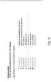
- FIG. 1a to 1i describes a user interface which, according to an embodiment of the invention, a building installation can be used to collect planning data before the installation is set up.
- a consulting tool gradually requests data for planning a lighting installation in a building.
- the project data such as the address and contact details of the customer (see Figure 1a ) asked what type of buildings should be equipped with lighting equipment (see Figure 1b ).
- the dimensions of the rooms are determined (see Figure 1c ) and the necessary protection class of the lights (see Figure 1d ) queried.
- further features are determined which relate to the automatic switching of the luminaire, for example by means of daylight threshold switching and by motion detection.
- the software automatically determines a proposal for the lighting devices in the building in question and their arrangement within the building (see Figure 1f ) and outputs a potential energy saving potential to be achieved (see Figure 1g ).
- the determined data are stored in a project file and can be called up in this file under the project name (see Figures 1h and 1i ). It is important to note that the data once recorded is saved permanently and is retained over the entire life cycle of the system. The data file therefore enables the relevant technical data to be documented beyond the planning phase. During the planning phase, the data collected during the consultation as well as any further data lock measurements and all information relevant to the planning can be included in the planning.
- each piece of equipment is assigned a unique identifier in accordance with the planning program.
- the equipment identification is also automatically saved in the data file. They can be used in the next step of the ordering phase of the system.
- a parts list is preferably created from the data file, which includes the exact details of the number and type of the lighting devices required and, if appropriate, further sensors or other building technology.
- a connection to an ERP system can be established automatically.
- a description of the scope of services can also be output. It lists all products, systems, functions, warranty services and installation and commissioning services. The data is visible to both the customer of the system and the provider.
- Possible dates for service are automatically coordinated after the order. All available service employees are automatically selected using a calendar. This enables optimal utilization of the staff.
- All relevant information for the parameterization of the system can also be read from the data file.
- the previously specified switch-on and switch-off times as well as run-on times and dimming levels can be saved on the relevant product.
- the operating devices can check themselves and report a current error status, which is also stored in the data file.
- suitable measures can be taken by service technicians. Defective equipment can be replaced directly. Examples of the acquisition of measured value data that indicate an error are in the Figures 2a to 2c shown.
- the measured values can include, in particular, the signal quality of the control data and the stability of the supply voltage.
- Appropriate measures are suggested if events outside of a target are detected. These measures can be sent directly to a service technician in the form of an electronic notification.
- these measures are also stored in the project file (so-called IQ project file) and are preferably stored in a cloud database.
- the system determines measurement data during operation with sensors within the system, for example temperatures, in particular the temperature of the component itself, the ambient temperature and temperature fluctuations (see Figures 3a to 3c ).
- the measured temperatures are preferably evaluated directly on the relevant network component in order to draw conclusions about possible problems. If a temperature range outside a specified specification is determined, a possible problem is pointed out on the one hand and a possible loss of guarantee if the component fails, on the other hand. All data is stored in the project file, so that both the customer of the system and the manufacturer can demonstrate whether an error that has occurred can be traced back to an operation of the relevant component outside of its specification.
- the project file can be used to determine the delivery status of the defective component in order to determine whether changes have been made by the customer. If a change has been made by the customer without the manufacturer's authorization, this information is useful to: to check the justification of the complaint.
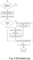
- a flow chart of this computer-aided method is in Figure 8 shown.
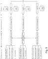
- Figure 9 an example is shown how a parameterization can be carried out with regard to run-on times, standby times and fading times on lighting components.
- the type of objects, the speed of the objects, the length of time the objects stay at a location and the distinction between movements of people and vehicles are recorded from motion sensors.
- follow-up times, standby times and fading times can be calculated from the data and a decision can be made as to whether a manual change of the parameterization is necessary.
- the determined parameterizations which may have been manually edited, are stored in the project file.
- Figure 10 shows an example of how it can be determined from the project file whether changes should be made to the installed sensors.
- the data stored in the planning in the project file is analyzed in order to determine a selection of the sensors, for example for environmental influences, interference, motion sensors, light sensor profiles and temperature profiles, and the necessary sensor products are selected. These are compared with the data available in the planning file of the project file in order to make a sensor selection.
- the method, the computer program and the network of the invention can be used in many areas.
- the network components can be installed in many places, e.g. on or in another component of a building installation, in a false ceiling, a concrete ceiling, a light wall, in the ground or concrete. Any form of structure, including residential and Office buildings, production halls and streets and paths.
- the area of application can relate to the renovation of existing systems or new buildings.
- the components can be installed inside the building or outside the building.
Landscapes
- Engineering & Computer Science (AREA)
- Automation & Control Theory (AREA)
- Computer Networks & Wireless Communication (AREA)
- Signal Processing (AREA)
- Management, Administration, Business Operations System, And Electronic Commerce (AREA)
Abstract

Description
- Die vorliegende Erfindung betrifft allgemein das Gebiet von Gebäudeinstallationsanlagen, worunter insbesondere Beleuchtungsanlagen sowie ggf. weitere zusätzliche Gebäudetechnik im Gebäude, in gebäudenahen Bereichen sowie in Außenbereichen des Gebäudes, verstanden wird. Insbesondere betrifft die Erfindung ein Analysetool, welches dazu dient, Daten, die vor, während und nach der Installation der Gebäudeanlage erhoben werden, auszuwerten.
- Gebäudeinstallationen, einschließlich der Beleuchtungstechnik, benötigen für größere Bauvorhaben eine umfangreiche Planung. Während des Lebenszyklus der Anlage sind laufende Wartungs-und Reparaturarbeiten die Regel. Schließlich stellt bei einem Rückbau der Gebäude sogar die Entsorgung ein kompliziertes Unterfangen dar, zu welchem die spezifischen Anlagenparameter bekannt sein müssen. Derzeit sind viele nicht miteinander vernetze Arbeitsschritte notwendig, um das unterschiedliche Wissen für die Planung der Gebäudetechnik, die Wartung und Entsorgung durchzuführen. Ein Problem besteht bereits darin, dass viel Wissen und Information zu einer Anlage über den laufenden Betrieb verloren geht und viel Klärungsbedarf zwischen den einzelnen Personen, welche die Anlage planen und betreiben, notwendig ist. Die Folge sind zeitaufwendige Notizen während der anfänglichen Planungsphase. Wenn die Anlage nicht so funktioniert, wie sie soll, sind häufig auch Streitigkeiten zwischen dem Hersteller der Anlage und dem Betreiber der Anlage zu erwarten. Wenn keine lückenlose Dokumentation der Anlage während des Betriebs vorliegt, ist häufig nicht zu klären, ob ein Planungsfehler oder ein Fehler beim Betrieb der Anlage vorlag. Schließlich ist sogar die Entsorgung der Anlage schwierig, weil nach Erreichen der Lebensdauer der Anlage häufig keine Dokumentation mehr vorhanden ist, um feststellen zu können, welche Komponenten verbaut worden sind und wie diese fachgerecht zu entsorgen sind.
- Aufgabe der vorliegenden Erfindung ist es, ein Beratungs- und Analysetool für Systeme der Gebäudetechnik bereitzustellen, welches die Planung und den Betrieb einer Anlage zur Gebäudetechnik unterstützt.
- Gelöst wird die Aufgabe durch ein Verfahren zur computergestützten Auswertung von Bedarfs- und Aufzeichngungsdaten an der Gebäudeinstallation gemäß Anspruch 1, sowie durch ein Computerprogramm nach Anspruch 14 und ein Netzwerk nach Anspruch 15.
- Ein Vorteil des computergestützten Auswertungsverfahrens der vorliegenden Erfindung besteht darin, dass über den gesamten Lebenszyklus einer Anlage der Gebäudeinstallation, d.h. bereits vor Beginn der Installation der Anlage bis zum Ende des Betriebes ein einzelnes computergestütztes Tool verwendet wird, um die Bedarfsdaten zu erfassen und die Betriebsdaten aufzuzeichnen. Dazu ist vorgesehen, dass alle Bedarfsdaten bereits vor Einrichten der Anlage erfasst werden und daraus die Spezifikationen für die Gebäudeinstallation ermittelt werden. Dies erfolgt computergestützt durch eine Software, welche die notwendigen Planungsdaten über ein Benutzerschnittstelle geführt abfragt. Zusätzlich können bereits Sensormessungen in dem Planungsstadium vorgenommen werden. Beispielsweise können Lichtverhältnisse durch Tageslicht im Bereich der geplanten Gebäudeinstallation, typische Bewegungsmuster von Personen und Kraftfahrzeugen im Bereich der Gebäudeinstallation sowie Temperatur- und Umwelteinflüsse aufgezeichnet werden. Alle diese Planungsdaten werden analysiert und darum sinnvolle Spezifikationen für die Gebäudeeinrichtung ermittelt. Diese Spezifikationen werden gespeichert und während des laufenden Betriebs der Anlage mit Sensordaten von Sensoren, die als Teil der Anlage installiert sind und laufend Messdaten aufzeichnen und weitergeben, verglichen. Daraus kann in vorteilhafter Weise während des Betriebs der Anlage überprüft werden, ob die Anlage auch die vorher definierten Spezifikationen erfüllt. Ferner kann während des Betriebs der Anlage auch auf Änderungen reagiert werden. Wenn beispielsweise festgestellt wird, dass die Durchschnittstemperatur in einer Produktionshalle höher als ursprünglich geplant ist oder die durch einen Bewegungssensor ausgelösten Einschaltzeiten einer Leuchte viel größer ist als ursprünglich geplant war, können entsprechend die Gebäudeinstallationen nach der Erstinstallation verändert werden. Alle notwendigen Ergebnisse der Analyse stehen sowohl dem Betreiber der Anlage als auch dem Hersteller der Anlage sowie den Kundendienstmitarbeitern zur Verfügung, da sie in einem Datenfile vorzugsweise in einer Datenbank einer Cloud gespeichert werden.
- Gemäß einer bevorzugten Ausführungsform erheben die Sensoren wenigstens einige der folgenden Messdaten: Umgebungsbedingungen, insbesondere Temperatur, Feuchtigkeit und/oder mechanische Erschütterung; Beleuchtungsstärke, insbesondere die durch Tageslicht und/oder künstliches Licht erzeugte Beleuchtungsstärke; Bewegungsdaten von Personen und/oder Kraftfahrzeugen, die sich im Bereich der Gebäudeinstallation aufhalten; Stabilität eines Versorgungsnetzwerkes; und Signalqualität von Datenkommunikationseinrichtungen. Diese Daten werden üblicherweise zur Planung einer Gebäudeinstallation berücksichtigt. Das Aufzeichnen der Daten ermöglicht es daher, den ordnungsgemäßen Betrieb der Anlage zu überwachen. Teilweise werden die Daten ohnehin aufgezeichnet, um den laufenden Betrieb der Anlage zu gewährleisten. Beispielsweise werden Bewegungsdaten von Personen und Kraftfahrzeugen erfasst, um Leuchten ein- bzw. auszuschalten. Eine Besonderheit besteht jedoch darin, dass diese Daten auch erfasst werden, um den ordnungsgemäßen Betrieb der Anlage zu überwachen. Beispielsweise kann festgestellt werden, dass eine Umgebungstemperatur viel höher ist, als ursprünglich geplant war. Dann ist mit einem vorzeitigen Ausfall der entsprechenden Gebäudeanlage zu rechnen. Aus den Bewegungsdaten, welche ohnehin erhoben werden, um z.B. Beleuchtungsanlage ein- und auszuschalten, kann ermittelt werden, ob die Schaltfrequenz höher als geplant ist. Auch dann ist mit einem vorzeitigen Ausfall der Anlage zu rechnen und müssen daher früher ausgetauscht werden. Bei Störungen der Stabilität des Versorgungsnetzwerkes oder bei Störungen der Signalqualität bei der notwendigen Datenkommunikation sind ggf. die für die Gebäudeeinrichtung vorgesehenen Notprogramme an die veränderte Situation anzupassen.
- Gemäß einer bevorzugten Ausführungsform umfasst das Analysieren ein Vergleichen von mit dem Sensor erhobenen Umgebungsbedingungen mit einem in den Planungsdaten für den betreffenden Ort des Sensors spezifizierten maximalen Bereich der entsprechenden Umgebungsbedingungen. Die Erhebung dieser Daten dient nicht nur dazu, um einen vorzeitigen Ausfall von Geräten der Gebäudeinstallation vorherzusagen. Sie können auch vom Hersteller der Anlage benutzt werden, um Regressansprüche vom Betreiber abzuwehren, wenn die Angaben des Betreibers der Anlage vor Installation nicht korrekt waren.
- Gemäß einer bevorzugten Ausführungsform umfasst das Analysieren ein Vergleichen des Energieverbrauchs der Gebäudeinstallation oder Teilen von dieser mit einem in den Planungsdaten spezifizierten maximalen Energieverbrauch der Gebäudeinstallation oder der betreffenden Teile der Gebäudeinstallation. Die systematische Auswertung des Energieverbrauchs von einzelnen Energieverbrauchern der Gebäudeinstallation oder Teilen der Gebäudeinstallation ermöglicht es, ein effizientes Energiemanagement zu betreiben. Es kann analysiert werden, wo technisch aufwendigere Lösungen zur Nutzung des Tageslichts rentabel sind. Allerdings kann auch festgestellt werden, dass die vom Betreiber der Anlage ursprünglich festgelegten Betriebszeiten überschritten werden, so dass nachvollzogen werden kann, warum die Anlage einen zu hohen Gesamtenergieverbrauch aufweist.
- Gemäß einer bevorzugten Ausführungsform umfasst das Analysieren ein Feststellen einer Fehlfunktion einer Komponente der Gebäudeinstallation, insbesondere einem Ausfall einer Komponente der Gebäudeinstallation. Bei einer detektierten Fehlfunktion kann direkt das entsprechende Ersatzteil bestellt werden. Eine aufwendige Fehlersuche vor Ort entfällt.
- Gemäß einer bevorzugten Ausführungsform sieht das Verfahren nach dem Analysieren vor, eine elektronische Benachrichtigung zu erzeugen, welche an einen Betreiber der Gebäudeinstallation, an einen Hersteller der Gebäudeinstallation und/oder an einen Servicetechniker für die Gebäudeinstallation versendet wird. Insbesondere kann die elektronisch erzeugte Nachricht an den Betreiber, Hersteller und Servicetechniker jeweils unterschiedliche Inhalte aufweisen. Die für den Betreiber, den Hersteller und den Servicetechniker relevanten Informationen sind durchaus unterschiedlich. Während der Betreiber der Anlage insbesondere wissen möchte, ob die Anlage entsprechend der vorher festgestellten Spezifikationen störungsfrei arbeitet, ist für den Hersteller wichtig, ob die Anlage auch entsprechend vorhergehend festgelegten Planungsdaten betrieben wird. Für den Servicetechniker ist es wichtig, direkt Informationen über anstehende Wartungsarbeiten und die notwendigen Bestellinformationen für auszutauschende Teile der Anlage zu erhalten.
- Gemäß einer bevorzugten Ausführungsform umfasst wenigstens eine der elektronischen Benachrichtigungen eine Empfehlung für den Austausch einer Komponente der Gebäudetechnik und/oder eine Veränderung eines Serviceintervalls einer Komponente der Gebäudetechnik.
- Gemäß einer bevorzugten Ausführungsform umfasst die Benachrichtigung eine Identifikation des Typs und/oder des Ortes der betreffenden Komponente.
- Gemäß einer bevorzugten Ausführungsform umfasst die Benachrichtigung einen Hinweis darauf, dass ein Sensor wenigstens zeitweise eine Abweichung der gemessenen Umgebungsbedingungen von dem in den Planungsdaten spezifizierten maximalen Bereich umfasst.
- Gemäß einer bevorzugten Ausführungsform umfasst das Analysieren eine statistische Analyse von Sensordaten, um das Auftreten von Messdaten außerhalb einer statistischen Bandbreite festzustellen. Das Analysieren der statistischen Abweichungen kann einen Selbstlernprozess beinhalten, so dass eine der statistischen Auswertung zu Grunde gelegte Bandbreite über den laufenden Betrieb der Gebäudeinstallation auf Grundlage der vorhergehenden Messdaten angepasst wird. Beispielsweise kann durch eine statistische Auswertung der Daten, ein Grund für eine Fehlfunktion festgestellt werden. Wenn beispielsweise ein Bewegungssensor ständig scheinbar viel zu häufige Bewegungen meldet und gleichzeitig in dem selben Zeitraum eine höhere Temperatur durch ein Belüftungsgerät festgestellt wird, kann daraus geschlossen werden, dass die Temperatur des Belüftungsgerätes eine Fehlfunktion in dem Bewegungsmelder hervorruft. Die Qualität einer solchen, durch statistische Auswertung festgestellten Fehler, kann durch den Selbstlernprozess laufend verbessert werden. Das System erkennt selbst, welche atypischen Messdaten von Sensoren voraussichtlich eine Fehlfunktion eines benachbarten Gerätes zur Folge haben, um vor einem Ausfall des betreffenden Gerätes früher zu warnen.
- Gemäß einer bevorzugten Ausführungsform werden die Planungsdaten, die Spezifikationen, die Sensordaten, die Ergebnisse des Analysierens und/oder die versandten Benachrichtigungen in einem einzelnen Datenfile gespeichert. Ein Vorteil dieser Ausführungsform besteht darin, dass alle Daten über den gesamten Lebenszyklus in einem Datenfile lückenlos aufgezeichnet werden. Dadurch erhöht sich die Möglichkeit, Fehlervorhersagen aus statistischen Daten zu ermitteln, wie vorhergehend ausgeführt. Ferner sind zur Forderung von Garantieansprüchen oder zur Abwehr von Regressansprüchen die notwendigen Daten, welche derartige Ansprüche für den Betreiber bzw. den Hersteller der Anlagen belegen können, jederzeit verfügbar. Ferner sind bei einem Rückbau oder einem Teilrückbau der Anlage noch alle Informationen enthalten, die ein fachgerechtes Entsorgen der Systemkomponenten oder ggf. ein Recycling der Komponenten der Gebäudeinstallation ermöglichen. Wenn beispielsweise festgestellt wird, dass ein Teil der Gebäudeinstallation aufgrund des Abrisses des Gebäudes bereits zurückgebaut werden muss, lange bevor die Lebenserwartung der Geräte erreicht ist, ist es möglich, auch eine Weiterverwendung der Geräte zu planen. Fernern sind alle Informationen über den Typ der verbauten Geräte gespeichert, so dass jederzeit ein geeignetes Ersatzgerät wiederbeschafft werden kann.
- Weitere Vorteile und Merkmale der vorliegenden Erfindung werden aus der nachfolgenden Beschreibung bevorzugter Ausführungsformen deutlich, die in Verbindung mit den beigefügten Figuren gegeben wird. In den Figuren ist Folgendes dargestellt:
- Figuren 1a bis 1i
- zeigen Benutzerschnittstellen einer Software zur Erhebung von Planungsdaten einer Gebäudeinstallation, und
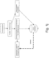
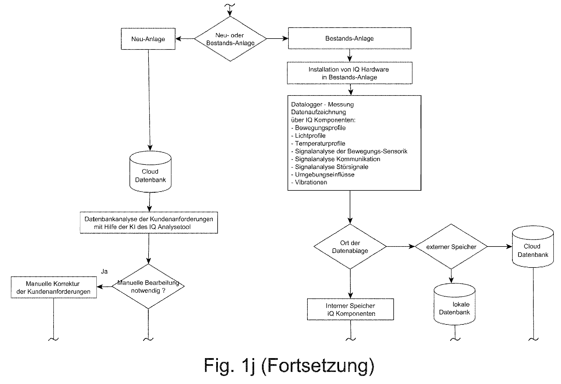
- Figur 1j
- zeigt ein Ablaufdiagramm einer Software zur Erhebung der Planungsdaten in einer Neu- und Bestandsanlage.
- Figuren 2a bis 2c
- zeigen Ablaufdiagramme einer Software zum Analysieren von Sensordaten betreffend die Signalqualität an Schnittstellen.
- Figuren 3a bis 3c
- zeigen Ablaufdiagramme einer Software betreffend das Analysieren von Temperaturprofilen.
- Figur 4
- zeigt ein Ablaufdiagramm einer Software zur Analyse von Störsignalen.
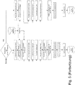
- Figur 5
- zeigt ein Ablaufdiagramm einer Software zur Analyse von Daten aus Orts- und Bewegungssensoren.
- Figur 6
- zeigt ein Ablaufdiagramm eine Software zur Analyse von Daten aus Sensoren, welche Bewegungseinflüsse messen.
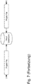
- Figur 7
- zeigt ein Ablaufdiagramm einer Software zur Aufzeichnung von Messwerten einer Vielzahl von Sensoren.
- Figur 8
- zeigt ein Ablaufdiagramm einer Software zur Behandlung von Kundenreklamationen.
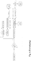
- Figur 9
- zeigt ein Ablaufdiagramm einer Software zur Verarbeitung von Daten aus Bewegungssensoren.
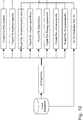
- Figur 10
- zeigt ein Ablaufdiagramm einer Software zur Sensorauswahl.
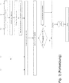
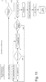
- Figur 11
- zeigt ein Ablaufdiagramm einer Software zur Analyse von Daten aus Objekterkennungs- und Bewegungssensoren.
- Bezugnehmend auf die
Figuren 1a bis 1i wird eine Benutzerschnittstelle beschrieben, die gemäß einer Ausführungsform der Erfindung zur Erhebung von Planungsdaten eine Gebäudeinstallation vor Einrichtung der Installation verwendet werden kann. Ein Beratungs-Tool fragt schrittweise Daten für die Planung einer Beleuchtungsinstallation in einem Gebäude ab. In dem vorliegenden Beispiel wird nach Erfassung der Projektdaten, wie die Adresse und die Kontaktdaten des Kunden (sieheFigur 1a ) abgefragt, welche Art von Gebäuden mit Beleuchtungseinrichtungen ausgerüstet werden sollen (sieheFigur 1b ). Im nächsten Schritt wird die Bemaßung der Räume festgelegt (sieheFigur 1c ) und die notwendige Schutzklasse der Leuchten (sieheFigur 1d ) abgefragt. Schließlich werden noch weitere Merkmale festgelegt, welche die automatische Schaltung der Leuchte, z.B. durch Tageslicht-Schwellwertschaltung und durch Bewegungserfassung, betreffen. Darin werden auch die Nachlaufzeiten sowie die Dimm-Level für die Leuchte festgelegt (sieheFigur 1e ). Auf Grundlage dieser Rahmenparameter ermittelt die Software automatisch einen Vorschlag für die Beleuchtungseinrichtungen in dem betreffenden Gebäude und deren Anordnung innerhalb des Gebäudes (sieheFigur 1f ) und gibt ein voraussichtlich zu erzielendes Energie-Einsparpotenzial aus (sieheFigur 1g ). Die ermittelten Daten werden in einem Projekt-File abgelegt und sind in diesem File unter der Projektbezeichnung abrufbar (sieheFiguren 1h und1i ). Wichtig ist dabei anzumerken, dass die einmal erfassten Daten dauerhaft gespeichert werden und über den gesamten Lebenszyklus der Anlage erhalten bleiben. Das Datenfile ermöglicht daher eine Dokumentation der relevanten technischen Daten über die Planungsphase hinaus. Während der Planungsphase können die bei der Beratung erhobenen Daten sowie ggf. weiter Datenlocker-Messungen und sämtliche Informationen, die für die Planung relevant sind, in die Planung einbezogen werden. Ferner ist berücksichtigt, dass auch Informationen aus anderen Daten-Files von bereits durchgeführten Projekten zur manuellen oder automatischen Planung herbeigezogen werden können. Hierzu werden alle notwendigen Informationen aus einer Datenbank, welche das Daten-File speichert, von allen an dem Projekt beteiligten Personen bezogen. Ein Ablaufdiagramm eines Computerprogramms, welches zur Erhebung der Planungsdaten in einer Neu- und Bestandsanlage verwendet werden kann, ist inFigur 1j dargestellt. Die Speicherung des Daten-Files kann erfolgen, wie in der deutschen Patentanmeldung mit dem Titel "Projektfile für Beleuchtungsanlagen" der gleichen Anmelderin mit demselben Anmeldetag beschrieben ist. Nach Bedarf ist auch eine Übersetzung in eine andere Sprache möglich, so dass die Bearbeitung auch an einem anderen Standort oder in einem anderen Land stattfinden kann. - Bei der Planung werden entsprechend dem Planungsprogramm jedem Betriebsmittel eine eindeutige Kennzeichnung zugewiesen. Auch die Betriebsmittelkennzeichnung wird in dem Datenfile automatisch gespeichert. Sie können im nächsten Schritt der Bestellphase der Anlage Verwendung finden. Vorzugsweise wird aus dem Daten-File eine Stückliste erstellt, welche die exakten Angaben der Anzahl und des Typs der benötigten Beleuchtungseinrichtungen sowie ggf. weitere Sensorik oder anderer Gebäudetechnik umfasst. Eine Verbindung zu einem Warenwirtschafts-System kann automatisch hergestellt werden. Ferner kann eine Beschreibung des Leistungsumfangs ausgegeben werden. Darin sind alle Produkte, Anlagen, Funktionen, Garantieleistungen und Montage- und Betriebnahmeleistungen aufgelistet. Die Daten sind sowohl für den Kunden der Anlage als auch für den Anbieter ersichtlich.
- Erfolgt die Bestellung der Produkte aus dem Angebot, werden alle relevanten Daten bei Bedarf an das Warenwirtschaftssystem exportiert, um alle relevanten Einkaufs- und Beschaffungsinformationen zu bekommen. Alle darin abgelegten Informationen zu Produkten und Einstellungen ggf. notwendigen Inbetriebnahme-Dienstleistungen sind auf einen Blick ersichtlich.
- Automatisch nach der Bestellung werden mögliche Termine für Service-Dienstleistungen abgestimmt. Alle verfügbaren Service-Mitarbeiter werden automatisch mit Hilfe eines Kalenders ausgesucht. Eine optimale Auslastung des Personals wird dadurch ermöglicht.
- Während der Produktion der Produkte der Gebäudeinstallation werden alle notwendigen Daten aus dem Daten-File ausgelesen und die Produkte können beispielsweise mit einem Aufkleber entsprechen markiert werden. Jedes Produkt und sein späterer Installationsort ist damit eindeutig identifizierbar.
- Aus dem Daten-File können ferner alle relevanten Informationen zur Parametrisierung der Anlage abgelesen werden. Beispielsweise können die vorher spezifizierten An- und Ausschaltzeiten sowie Nachlaufzeiten und Dimm-Level an dem betreffenden Produkt gespeichert werden.
- Dies erleichtert die Montage der Produkte durch einen Servicetechniker vor Ort. Aus der Identifikation des Produkts kann unmittelbar auf dem Montageort geschlossen werden. Falls vor oder während der Installation der Anlage noch Änderungen vorgenommen werden, werden diese ebenfalls in dem Daten-File erfasst, so dass auch später jederzeit nachvollziehbar ist, welche Produkte an welchem Ort installiert worden sind.
- Nach Inbetriebnahme der Anlage können sich die Betriebsgeräte selbst überprüfen und einen aktuellen Fehlerzustand melden, welcher ebenfalls in das Daten-File abgelegt wird. Auf diese Weise können geeignete Maßnahmen durch Servicetechniker ergriffen werden. Ein Austausch eines defekten Betriebsmittel kann direkt erfolgen. Beispiele für die Erfassung von Messwertdaten, welche auf einen Fehler schließen lassen, sind in den
Figuren 2a bis 2c dargestellt. Die Messwerte können insbesondere die Signalqualität der Steuerdaten sowie die Stabilität der Versorgungsspannung umfassen. Bei Feststellen von Ereignissen außerhalb einer Vorgabe werden geeignete Maßnahmen vorgeschlagen. Diese Maßnahmen können in Form einer elektronischen Benachrichtigung direkt an einen Servicetechniker übermittelt werden. Ferner werden auch diese Maßnahmen in dem Projekt-File (sogenanntes IQ-Projekt-File) gespeichert und vorzugsweise in einer Cloud-Datenbank abgelegt. - Ferner werden von der Anlage im laufenden Betrieb mit Sensoren innerhalb der Anlage Messdaten ermittelt, z.B. Temperaturen, insbesondere die Temperatur der Komponente selbst, die Umgebungstemperatur sowie Temperaturschwankungen (siehe
Figuren 3a bis 3c ). Die gemessenen Temperaturen werden vorzugsweise direkt an der betreffenden Netzwerkkomponente ausgewertet, um auf mögliche Probleme Rückschlüsse zu ziehen. Wenn ein Temperaturbereich außerhalb einer vorgegebenen Spezifikation festgestellt wird, wird einerseits auf ein mögliches Problem hingewiesen und andererseits auch auf einen möglichen Garantieverlust bei Ausfall der Komponente aufmerksam gemacht. Alle Daten werden in dem Projekt-File abgelegt, so dass sowohl für den Kunden der Anlage als auch für den Hersteller nachweisbar ist, ob ein aufgetretener Fehler auf einen Betrieb der betreffenden Komponente außerhalb ihrer Spezifikation zurückzuführen ist. - Beispiele für die Fehlererfassung aus auffälligen Messwerten sind in
Figur 4 in Hinblick auf Störsignale, inFigur 5 in Hinblick auf Meldungen von Bewegungssensoren und inFigur 6 in Hinblick auf Umgebungsbedingungen, insbesondere Luftfeuchtigkeit und flüchtige organische Verbindungen (VOC), beschrieben. - Eine Übersicht von erfassten Messwerten ist in
Figur 7 dargestellt. - Im Falle einer Kundenreklamation kann aus dem Projekt-File ermittelt werden, wie der Auslieferungszustand der fehlerhaften Komponente war, um festzustellen, ob kundenseitig Änderungen vorgenommen worden sind. Falls kundenseitig eine Änderung vorgenommen worden ist, ohne dass diese vom Hersteller autorisiert war, ist diese Information nützlich, um die Berechtigung der Reklamation zu prüfen. Ein Ablaufdiagramm dieses computergestützten Verfahrens ist in
Figur 8 dargestellt. - In
Figur 9 ist ein Beispiel gezeigt, wie eine Parametrisierung im Hinblick auf Nachlaufzeiten, Standby-Zeiten und Fading-Zeiten an Beleuchtungskomponenten erfolgen kann. Dazu werden aus Bewegungssensoren die Art der Objekte, die Geschwindigkeit der Objekte, die Verweildauer der Objekte an einem Ort und Unterscheidung zwischen Personen- und Fahrzeugbewegungen erfasst. Aus den Daten können Nachlaufzeiten, Standby-Zeiten und Fading-Zeiten berechnet werden, sowie entschieden werden, ob eine manuelle Änderung der Parametrisierung notwendig ist. Die ermittelten und ggf. manuell nachbearbeiteten Parametrisierungen werden in dem Projekt-File abgelegt. -
Figur 10 zeigt ein Beispiel, wie aus dem Projekt-File ermittelt werden kann, ob Änderungen an der installierten Sensorik vorgenommen werden sollen. Es werden die aus der Planung im Projekt-File abgelegten Daten analysiert, um eine Auswahl der Sensoren z.B. für Umgebungseinflüsse, Störeinflüsse, Bewegungssensoren, Lichtsensorprofile und Temperaturprofile ermittelt und die notwendigen Sensorprodukte ausgewählt. Diese werden abgeglichen mit den in der Planungsdatei des Projekt-Fils vorhandenen Daten, um eine Sensorauswahl zu treffen. - Mögliche Anwendung finden das Verfahren, das Computerprogramm und das Netzwerk der Erfindung in vielen Bereichen. Die Netzwerkkomponenten lassen sich an vielen Orten verbauen, z.B. an oder in einer anderen Komponente einer Gebäudeinstallation, in einer Abhängdecke, einer Betondecke, einer Leuchtbauwand, im Erdreich oder Beton. Als Gebäude in dieser Anmeldung werden jede Form von Bauwerken bezeichnet, einschließlich Wohn- und Bürohäusern, Produktionshallen sowie Straßen und Wege. Der Einsatzbereich kann die Sanierung von Bestandsanlagen oder den Neubau betreffen. Die Komponenten können innerhalb der Gebäude oder im Außenbereich der Gebäude verbaut werden.
Claims (15)
- Verfahren zur computergestützten Auswertung von Bedarfs-und Aufzeichnungsdaten einer Gebäudeinstallation, insbesondere einer Beleuchtungsanlage, umfassend
vor Einrichtung einer Gebäudeinstallation Erhebung von Planungsdaten für die Gebäudeinstallation;
Ermitteln von Spezifikationen der Gebäudeinstallation aus den Planungsdaten;
nach Einrichten der Gebäudeinstallation, Aufzeichnen von Sensordaten aus Sensoren, welche Bestandteile der Gebäudeinstallation sind; und
Analysieren der Sensordaten zum Feststellen, ob die ermittelten Spezifikationen bei Betreiben der Gebäudeinstallation eingehalten werden. - Verfahren nach Anspruch 1, wobei die Sensoren wenigstens einige der folgenden Messdaten erheben:Umgebungsbedingungen, insbesondere Temperatur, Feuchtigkeit und/oder mechanische Erschütterung;Beleuchtungsstärke, insbesondere die durch Tageslicht und/oder künstliches Licht erzeugte Beleuchtungsstärke; Bewegungsdaten von Personen und Kraftfahrzeugen, die sich im Bereich der Gebäudeinstallation aufhalten; Stabilität eines Versorgungsnetzwerkes; undSignalqualität von Datenkommunikationseinrichtungen.
- Verfahren nach einem der vorhergehenden Ansprüche, wobei das Analysieren ein Vergleichen von mit dem Sensor erhobenen Umgebungsbedingungen mit einem in den Planungsdaten für den betreffenden Ort des Sensors spezifizierten maximalen Bereich der entsprechenden Umgebungsbedingungen umfasst.
- Verfahren nach einem der vorhergehenden Ansprüche, wobei das Analysieren ein Vergleichen des Energieverbrauchs der Gebäudeinstallation oder Teilen von dieser mit einem in den Planungsdaten spezifizierten maximalen Energieverbrauch der Gebäudeinstallation oder der betreffenden Teile der Gebäudeinstallation umfasst.
- Verfahren nach einem der vorhergehenden Ansprüche, wobei das Analysieren ein Feststellen einer Fehlfunktion einer Komponente der Gebäudeinstallation, insbesondere einen Ausfall einer Komponente der Gebäudeinstallation, umfasst.
- Verfahren nach einem der vorhergehenden Ansprüche, wobei das Verfahren nach dem Analysieren vorsieht, eine elektronische Benachrichtigung zu erzeugen, welche an einen Betreiber der Gebäudeinstallation, an einen Hersteller der Gebäudeinstallation und/oder an einen Servicetechniker für die Gebäudeinstallation versendet wird.
- Verfahren nach Anspruch 6, wobei die elektronisch erzeugte Nachricht an den Betreiber, Hersteller und Servicetechniker jeweils unterschiedliche Inhalte aufweist.
- Verfahren nach Anspruch 6 oder 7, wobei wenigstens eine der elektronischen Benachrichtigungen eine Empfehlung für den Austausch einer Komponente der Gebäudetechnik und/oder eine Veränderung eines Serviceintervalls einer Komponente der Gebäudetechnik umfasst.
- Verfahren nach Anspruch 8, wobei die Benachrichtigung eine Identifikation des Typs und/oder des Ortes der betreffenden Komponente umfasst.
- Verfahren nach einem der Ansprüche 6 bis 9 mit Rückbezug auf Anspruch 3, wobei die Benachrichtigung einen Hinweis darauf umfasst, dass ein Sensor wenigstens zeitweise eine Abweichung der gemessenen Umgebungsbedingungen von dem in den Planungsdaten spezifizierten maximalen Bereich umfasst.
- Verfahren nach einem der vorhergehenden Ansprüche, wobei das Analysieren eine statistische Analyse von Sensordaten umfasst, um das Auftreten von Messdaten außerhalb einer statistischen Bandbreite festzustellen.
- Verfahren nach Anspruch 11, wobei das Analysieren der statistischen Abweichungen einen Selbstlernprozess beinhaltet, so dass eine der statistischen Auswertung zu Grunde gelegte Bandbreite über den laufenden Betrieb der Gebäudeinstallation auf Grundlage der vorhergehenden Messdaten angepasst wird.
- Verfahren nach einem der vorhergehenden Ansprüche, wobei die Planungsdaten, die Spezifikationen, die Sensordaten, die Ergebnisse des Analysierens und/oder bei Rückbezug auf einen der Ansprüche 6 bis 12 die versandten Benachrichtigungen in einem einzelnen Datenfile gespeichert werden.
- Computerprogramm, welches Anweisungen umfasst, die, wenn sie auf einem Computer ausgeführt werden, ein Verfahren nach einem der vorhergehenden Ansprüche durchführt.
- Netzwerk aus mehreren Netzwerkkomponenten, wobei die Gebäudeinstallation Teil der Netzwerkkomponenten ist und das Netzwerk dazu eingerichtet ist, ein Verfahren nach einem der Ansprüche 1 bis 13 durchzuführen.
Priority Applications (1)
| Application Number | Priority Date | Filing Date | Title |
|---|---|---|---|
| SI201930274T SI3664381T1 (sl) | 2018-12-06 | 2019-12-06 | Analizno orodje za ovrednotenje podatkov v zvezi s potrebami in beleženjem za instalacije za razsvetljavo |
Applications Claiming Priority (2)
| Application Number | Priority Date | Filing Date | Title |
|---|---|---|---|
| DE102018009603 | 2018-12-06 | ||
| DE102019103896.0A DE102019103896A1 (de) | 2018-12-06 | 2019-02-15 | Analysetool zur Auswertung von Bedarfs- und Aufzeichnungsdaten von Beleuchtungsanlagen |
Publications (2)
| Publication Number | Publication Date |
|---|---|
| EP3664381A1 true EP3664381A1 (de) | 2020-06-10 |
| EP3664381B1 EP3664381B1 (de) | 2022-06-15 |
Family
ID=68808120
Family Applications (1)
| Application Number | Title | Priority Date | Filing Date |
|---|---|---|---|
| EP19214040.8A Active EP3664381B1 (de) | 2018-12-06 | 2019-12-06 | Analysetool zur auswertung von bedarfs- und aufzeichnungsdaten von beleuchtungsanlagen |
Country Status (4)
| Country | Link |
|---|---|
| EP (1) | EP3664381B1 (de) |
| DK (1) | DK3664381T3 (de) |
| PL (1) | PL3664381T3 (de) |
| SI (1) | SI3664381T1 (de) |
Citations (4)
| Publication number | Priority date | Publication date | Assignee | Title |
|---|---|---|---|---|
| US20160212576A1 (en) * | 2011-02-22 | 2016-07-21 | Asoka Usa Corporation | Sensor having an integrated zigbee® device for communication with zigbee® enabled appliances to control and monitor zigbee® enabled appliances |
| US20170038753A1 (en) * | 2014-04-25 | 2017-02-09 | Philips Lighting Holding B.V. | System and method for maintaining building automation system performance |
| DE102016110456A1 (de) * | 2016-03-29 | 2017-10-05 | Abb Ag | Verfahren und Vorrichtung zur Kommissionierung eines Gebäudeautomationssystem |
| EP3308227A1 (de) * | 2015-06-10 | 2018-04-18 | Johnson Controls Technology Company | Gebäudeautomationssystem mit intelligenten kommunikationssteuergeräten für gebäudeausrüstungen |
-
2019
- 2019-12-06 PL PL19214040.8T patent/PL3664381T3/pl unknown
- 2019-12-06 DK DK19214040.8T patent/DK3664381T3/da active
- 2019-12-06 EP EP19214040.8A patent/EP3664381B1/de active Active
- 2019-12-06 SI SI201930274T patent/SI3664381T1/sl unknown
Patent Citations (4)
| Publication number | Priority date | Publication date | Assignee | Title |
|---|---|---|---|---|
| US20160212576A1 (en) * | 2011-02-22 | 2016-07-21 | Asoka Usa Corporation | Sensor having an integrated zigbee® device for communication with zigbee® enabled appliances to control and monitor zigbee® enabled appliances |
| US20170038753A1 (en) * | 2014-04-25 | 2017-02-09 | Philips Lighting Holding B.V. | System and method for maintaining building automation system performance |
| EP3308227A1 (de) * | 2015-06-10 | 2018-04-18 | Johnson Controls Technology Company | Gebäudeautomationssystem mit intelligenten kommunikationssteuergeräten für gebäudeausrüstungen |
| DE102016110456A1 (de) * | 2016-03-29 | 2017-10-05 | Abb Ag | Verfahren und Vorrichtung zur Kommissionierung eines Gebäudeautomationssystem |
Also Published As
| Publication number | Publication date |
|---|---|
| PL3664381T3 (pl) | 2022-09-12 |
| EP3664381B1 (de) | 2022-06-15 |
| DK3664381T3 (da) | 2022-09-19 |
| SI3664381T1 (sl) | 2022-10-28 |
Similar Documents
| Publication | Publication Date | Title |
|---|---|---|
| EP1628899B1 (de) | Verfahren und vorrichtung zur wartung einer aufzugs- oder fahrtreppenanlage | |
| EP3077878B1 (de) | Computer-implementiertes verfahren und system zur automatischen überwachung und statusermittlung ganzer prozessabschnitte in einer process unit | |
| DE112017000687T5 (de) | Geräteverwaltungsvorrichtung, Geräteverwaltungssystem, computerlesbares Medium und Geräteverwaltunsverfahren | |
| EP2864847B1 (de) | Überwachung einer ersten ausrüstung einer technischen anlage zur herstellung eines produkts | |
| DE102017203836A1 (de) | Verfahren und System zum Bestimmen einer erwarteten Lebensdauer eines elektrischen Betriebsmittels | |
| EP3699704B1 (de) | System und verfahren zum überprüfen von systemanforderungen von cyber-physikalischen systemen | |
| EP3602146B1 (de) | Verfahren und vorrichtung zur ermittlung der wahrscheinlichkeit für einen schimmelpilz- und/oder feuchteschaden in einem gebäude | |
| DE102008012097B4 (de) | Überwachungseinrichtung für den Betrieb von Schaltschrankgeräten | |
| DE102019103896A1 (de) | Analysetool zur Auswertung von Bedarfs- und Aufzeichnungsdaten von Beleuchtungsanlagen | |
| DE102013226186A1 (de) | Verfahren zur Instandhaltung von Betriebsmitteln großtechnischer Anlagen oder Fabrikationsstätten | |
| DE102009038351A1 (de) | Verfahren zur automatischen Erkennung und Darstellung des Betriebs, und der Arbeits- und Funktionsweise von gebäudetechnischen und/oder produktionstechnischen Anlagen im Hinblick auf deren Energieeffizienz | |
| EP3664381B1 (de) | Analysetool zur auswertung von bedarfs- und aufzeichnungsdaten von beleuchtungsanlagen | |
| WO2011000367A1 (de) | Verfahren und vorrichtung zur vereinfachten fehlerverarbeitung an einer werkzeugmaschine | |
| EP3623890A1 (de) | Verfahren zum überwachen von mehreren verfahrenstechnischen anlagen | |
| EP2492701A1 (de) | Verfahren und Vorrichtung zum Testen einer Windturbinenanlage | |
| DE3601665A1 (de) | Verfahren zur ermittlung der optimalen betriebsdauer wenigstens einer stromverbrauchenden lichtquelle, insbesondere einer leuchtstoffroehre | |
| EP3664012A1 (de) | Projektfile für beleuchtungsanlagen | |
| WO2017114592A1 (de) | Verfahren zur überprüfung der reagierfähigkeit eines sensors unter berücksichtigung des neuzustands | |
| EP2778414B1 (de) | Messwertstandardisierung | |
| EP3217766B1 (de) | Verfahren zum betrieb eines leuchtmittels | |
| EP3664380B1 (de) | Upgradbares stufenkonzept für beleuchtungssysteme | |
| EP0309829A1 (de) | Verfahren und Vorrichtung zur Überwachung der mechanischen Integrität einer Komponente | |
| DE102018201838A1 (de) | Verfahren zum Einrichten und Überwachen einer Anlage | |
| DE10030305A1 (de) | Verfahren und System zur Optimierung der Instandhaltung von Fahrwegen, insbesondere von Gleisanlagen | |
| EP3633476B1 (de) | Verfahren, vorrichtung und system zum übertragen von maschineninformationen an eine serviceeinrichtung |
Legal Events
| Date | Code | Title | Description |
|---|---|---|---|
| PUAI | Public reference made under article 153(3) epc to a published international application that has entered the european phase |
Free format text: ORIGINAL CODE: 0009012 |
|
| STAA | Information on the status of an ep patent application or granted ep patent |
Free format text: STATUS: THE APPLICATION HAS BEEN PUBLISHED |
|
| AK | Designated contracting states |
Kind code of ref document: A1 Designated state(s): AL AT BE BG CH CY CZ DE DK EE ES FI FR GB GR HR HU IE IS IT LI LT LU LV MC MK MT NL NO PL PT RO RS SE SI SK SM TR |
|
| AX | Request for extension of the european patent |
Extension state: BA ME |
|
| STAA | Information on the status of an ep patent application or granted ep patent |
Free format text: STATUS: REQUEST FOR EXAMINATION WAS MADE |
|
| 17P | Request for examination filed |
Effective date: 20201207 |
|
| RBV | Designated contracting states (corrected) |
Designated state(s): AL AT BE BG CH CY CZ DE DK EE ES FI FR GB GR HR HU IE IS IT LI LT LU LV MC MK MT NL NO PL PT RO RS SE SI SK SM TR |
|
| GRAP | Despatch of communication of intention to grant a patent |
Free format text: ORIGINAL CODE: EPIDOSNIGR1 |
|
| STAA | Information on the status of an ep patent application or granted ep patent |
Free format text: STATUS: GRANT OF PATENT IS INTENDED |
|
| INTG | Intention to grant announced |
Effective date: 20220105 |
|
| GRAS | Grant fee paid |
Free format text: ORIGINAL CODE: EPIDOSNIGR3 |
|
| GRAA | (expected) grant |
Free format text: ORIGINAL CODE: 0009210 |
|
| STAA | Information on the status of an ep patent application or granted ep patent |
Free format text: STATUS: THE PATENT HAS BEEN GRANTED |
|
| AK | Designated contracting states |
Kind code of ref document: B1 Designated state(s): AL AT BE BG CH CY CZ DE DK EE ES FI FR GB GR HR HU IE IS IT LI LT LU LV MC MK MT NL NO PL PT RO RS SE SI SK SM TR |
|
| REG | Reference to a national code |
Ref country code: CH Ref legal event code: EP Ref country code: GB Ref legal event code: FG4D Free format text: NOT ENGLISH |
|
| REG | Reference to a national code |
Ref country code: IE Ref legal event code: FG4D Free format text: LANGUAGE OF EP DOCUMENT: GERMAN |
|
| REG | Reference to a national code |
Ref country code: DE Ref legal event code: R096 Ref document number: 502019004642 Country of ref document: DE |
|
| REG | Reference to a national code |
Ref country code: AT Ref legal event code: REF Ref document number: 1499062 Country of ref document: AT Kind code of ref document: T Effective date: 20220715 |
|
| REG | Reference to a national code |
Ref country code: NL Ref legal event code: FP |
|
| REG | Reference to a national code |
Ref country code: DK Ref legal event code: T3 Effective date: 20220914 Ref country code: NO Ref legal event code: T2 Effective date: 20220615 |
|
| REG | Reference to a national code |
Ref country code: FI Ref legal event code: FGE |
|
| REG | Reference to a national code |
Ref country code: SE Ref legal event code: TRGR |
|
| REG | Reference to a national code |
Ref country code: LT Ref legal event code: MG9D |
|
| REG | Reference to a national code |
Ref country code: GR Ref legal event code: EP Ref document number: 20220401532 Country of ref document: GR Effective date: 20221010 |
|
| PG25 | Lapsed in a contracting state [announced via postgrant information from national office to epo] |
Ref country code: LT Free format text: LAPSE BECAUSE OF FAILURE TO SUBMIT A TRANSLATION OF THE DESCRIPTION OR TO PAY THE FEE WITHIN THE PRESCRIBED TIME-LIMIT Effective date: 20220615 Ref country code: HR Free format text: LAPSE BECAUSE OF FAILURE TO SUBMIT A TRANSLATION OF THE DESCRIPTION OR TO PAY THE FEE WITHIN THE PRESCRIBED TIME-LIMIT Effective date: 20220615 Ref country code: BG Free format text: LAPSE BECAUSE OF FAILURE TO SUBMIT A TRANSLATION OF THE DESCRIPTION OR TO PAY THE FEE WITHIN THE PRESCRIBED TIME-LIMIT Effective date: 20220915 |
|
| PG25 | Lapsed in a contracting state [announced via postgrant information from national office to epo] |
Ref country code: RS Free format text: LAPSE BECAUSE OF FAILURE TO SUBMIT A TRANSLATION OF THE DESCRIPTION OR TO PAY THE FEE WITHIN THE PRESCRIBED TIME-LIMIT Effective date: 20220615 Ref country code: LV Free format text: LAPSE BECAUSE OF FAILURE TO SUBMIT A TRANSLATION OF THE DESCRIPTION OR TO PAY THE FEE WITHIN THE PRESCRIBED TIME-LIMIT Effective date: 20220615 |
|
| PG25 | Lapsed in a contracting state [announced via postgrant information from national office to epo] |
Ref country code: SM Free format text: LAPSE BECAUSE OF FAILURE TO SUBMIT A TRANSLATION OF THE DESCRIPTION OR TO PAY THE FEE WITHIN THE PRESCRIBED TIME-LIMIT Effective date: 20220615 Ref country code: SK Free format text: LAPSE BECAUSE OF FAILURE TO SUBMIT A TRANSLATION OF THE DESCRIPTION OR TO PAY THE FEE WITHIN THE PRESCRIBED TIME-LIMIT Effective date: 20220615 Ref country code: RO Free format text: LAPSE BECAUSE OF FAILURE TO SUBMIT A TRANSLATION OF THE DESCRIPTION OR TO PAY THE FEE WITHIN THE PRESCRIBED TIME-LIMIT Effective date: 20220615 Ref country code: PT Free format text: LAPSE BECAUSE OF FAILURE TO SUBMIT A TRANSLATION OF THE DESCRIPTION OR TO PAY THE FEE WITHIN THE PRESCRIBED TIME-LIMIT Effective date: 20221017 Ref country code: ES Free format text: LAPSE BECAUSE OF FAILURE TO SUBMIT A TRANSLATION OF THE DESCRIPTION OR TO PAY THE FEE WITHIN THE PRESCRIBED TIME-LIMIT Effective date: 20220615 Ref country code: EE Free format text: LAPSE BECAUSE OF FAILURE TO SUBMIT A TRANSLATION OF THE DESCRIPTION OR TO PAY THE FEE WITHIN THE PRESCRIBED TIME-LIMIT Effective date: 20220615 Ref country code: CZ Free format text: LAPSE BECAUSE OF FAILURE TO SUBMIT A TRANSLATION OF THE DESCRIPTION OR TO PAY THE FEE WITHIN THE PRESCRIBED TIME-LIMIT Effective date: 20220615 |
|
| PG25 | Lapsed in a contracting state [announced via postgrant information from national office to epo] |
Ref country code: IS Free format text: LAPSE BECAUSE OF FAILURE TO SUBMIT A TRANSLATION OF THE DESCRIPTION OR TO PAY THE FEE WITHIN THE PRESCRIBED TIME-LIMIT Effective date: 20221015 |
|
| REG | Reference to a national code |
Ref country code: DE Ref legal event code: R097 Ref document number: 502019004642 Country of ref document: DE |
|
| PG25 | Lapsed in a contracting state [announced via postgrant information from national office to epo] |
Ref country code: AL Free format text: LAPSE BECAUSE OF FAILURE TO SUBMIT A TRANSLATION OF THE DESCRIPTION OR TO PAY THE FEE WITHIN THE PRESCRIBED TIME-LIMIT Effective date: 20220615 |
|
| PLBE | No opposition filed within time limit |
Free format text: ORIGINAL CODE: 0009261 |
|
| STAA | Information on the status of an ep patent application or granted ep patent |
Free format text: STATUS: NO OPPOSITION FILED WITHIN TIME LIMIT |
|
| 26N | No opposition filed |
Effective date: 20230316 |
|
| PGFP | Annual fee paid to national office [announced via postgrant information from national office to epo] |
Ref country code: IT Payment date: 20221231 Year of fee payment: 4 |
|
| PG25 | Lapsed in a contracting state [announced via postgrant information from national office to epo] |
Ref country code: LU Free format text: LAPSE BECAUSE OF NON-PAYMENT OF DUE FEES Effective date: 20221206 |
|
| PG25 | Lapsed in a contracting state [announced via postgrant information from national office to epo] |
Ref country code: IE Free format text: LAPSE BECAUSE OF NON-PAYMENT OF DUE FEES Effective date: 20221206 |
|
| PG25 | Lapsed in a contracting state [announced via postgrant information from national office to epo] |
Ref country code: HU Free format text: LAPSE BECAUSE OF FAILURE TO SUBMIT A TRANSLATION OF THE DESCRIPTION OR TO PAY THE FEE WITHIN THE PRESCRIBED TIME-LIMIT; INVALID AB INITIO Effective date: 20191206 |
|
| PG25 | Lapsed in a contracting state [announced via postgrant information from national office to epo] |
Ref country code: CY Free format text: LAPSE BECAUSE OF FAILURE TO SUBMIT A TRANSLATION OF THE DESCRIPTION OR TO PAY THE FEE WITHIN THE PRESCRIBED TIME-LIMIT Effective date: 20220615 |
|
| PG25 | Lapsed in a contracting state [announced via postgrant information from national office to epo] |
Ref country code: MK Free format text: LAPSE BECAUSE OF FAILURE TO SUBMIT A TRANSLATION OF THE DESCRIPTION OR TO PAY THE FEE WITHIN THE PRESCRIBED TIME-LIMIT Effective date: 20220615 |
|
| PG25 | Lapsed in a contracting state [announced via postgrant information from national office to epo] |
Ref country code: MC Free format text: LAPSE BECAUSE OF FAILURE TO SUBMIT A TRANSLATION OF THE DESCRIPTION OR TO PAY THE FEE WITHIN THE PRESCRIBED TIME-LIMIT Effective date: 20220615 |
|
| PG25 | Lapsed in a contracting state [announced via postgrant information from national office to epo] |
Ref country code: MC Free format text: LAPSE BECAUSE OF FAILURE TO SUBMIT A TRANSLATION OF THE DESCRIPTION OR TO PAY THE FEE WITHIN THE PRESCRIBED TIME-LIMIT Effective date: 20220615 |
|
| PG25 | Lapsed in a contracting state [announced via postgrant information from national office to epo] |
Ref country code: MT Free format text: LAPSE BECAUSE OF FAILURE TO SUBMIT A TRANSLATION OF THE DESCRIPTION OR TO PAY THE FEE WITHIN THE PRESCRIBED TIME-LIMIT Effective date: 20220615 |
|
| PG25 | Lapsed in a contracting state [announced via postgrant information from national office to epo] |
Ref country code: BG Free format text: LAPSE BECAUSE OF FAILURE TO SUBMIT A TRANSLATION OF THE DESCRIPTION OR TO PAY THE FEE WITHIN THE PRESCRIBED TIME-LIMIT Effective date: 20220615 |
|
| PG25 | Lapsed in a contracting state [announced via postgrant information from national office to epo] |
Ref country code: BG Free format text: LAPSE BECAUSE OF FAILURE TO SUBMIT A TRANSLATION OF THE DESCRIPTION OR TO PAY THE FEE WITHIN THE PRESCRIBED TIME-LIMIT Effective date: 20220615 |
|
| PG25 | Lapsed in a contracting state [announced via postgrant information from national office to epo] |
Ref country code: TR Free format text: LAPSE BECAUSE OF FAILURE TO SUBMIT A TRANSLATION OF THE DESCRIPTION OR TO PAY THE FEE WITHIN THE PRESCRIBED TIME-LIMIT Effective date: 20220615 |
|
| REG | Reference to a national code |
Ref country code: CH Ref legal event code: U11 Free format text: ST27 STATUS EVENT CODE: U-0-0-U10-U11 (AS PROVIDED BY THE NATIONAL OFFICE) Effective date: 20260101 |
|
| PGFP | Annual fee paid to national office [announced via postgrant information from national office to epo] |
Ref country code: GB Payment date: 20251218 Year of fee payment: 7 |
|
| PGFP | Annual fee paid to national office [announced via postgrant information from national office to epo] |
Ref country code: NO Payment date: 20251216 Year of fee payment: 7 |
|
| PGFP | Annual fee paid to national office [announced via postgrant information from national office to epo] |
Ref country code: AT Payment date: 20251215 Year of fee payment: 7 |
|
| PGFP | Annual fee paid to national office [announced via postgrant information from national office to epo] |
Ref country code: FI Payment date: 20251216 Year of fee payment: 7 Ref country code: DK Payment date: 20251217 Year of fee payment: 7 |
|
| PGFP | Annual fee paid to national office [announced via postgrant information from national office to epo] |
Ref country code: NL Payment date: 20251217 Year of fee payment: 7 Ref country code: FR Payment date: 20251217 Year of fee payment: 7 |
|
| PGFP | Annual fee paid to national office [announced via postgrant information from national office to epo] |
Ref country code: GR Payment date: 20251215 Year of fee payment: 7 Ref country code: BE Payment date: 20251223 Year of fee payment: 7 |
|
| PGFP | Annual fee paid to national office [announced via postgrant information from national office to epo] |
Ref country code: SE Payment date: 20251217 Year of fee payment: 7 |
|
| PGFP | Annual fee paid to national office [announced via postgrant information from national office to epo] |
Ref country code: PL Payment date: 20251120 Year of fee payment: 7 |
|
| PGFP | Annual fee paid to national office [announced via postgrant information from national office to epo] |
Ref country code: SI Payment date: 20251124 Year of fee payment: 7 |
|
| PGFP | Annual fee paid to national office [announced via postgrant information from national office to epo] |
Ref country code: DE Payment date: 20251222 Year of fee payment: 7 |
|
| PGFP | Annual fee paid to national office [announced via postgrant information from national office to epo] |
Ref country code: CH Payment date: 20260101 Year of fee payment: 7 |