EP3663964A1 - Verfahren zur aufnahme von fingervenenbildern - Google Patents
Verfahren zur aufnahme von fingervenenbildern Download PDFInfo
- Publication number
- EP3663964A1 EP3663964A1 EP17920381.5A EP17920381A EP3663964A1 EP 3663964 A1 EP3663964 A1 EP 3663964A1 EP 17920381 A EP17920381 A EP 17920381A EP 3663964 A1 EP3663964 A1 EP 3663964A1
- Authority
- EP
- European Patent Office
- Prior art keywords
- finger
- finger vein
- sensor
- infrared light
- infrared
- Prior art date
- Legal status (The legal status is an assumption and is not a legal conclusion. Google has not performed a legal analysis and makes no representation as to the accuracy of the status listed.)
- Granted
Links
Images


Classifications
-
- G—PHYSICS
- G06—COMPUTING OR CALCULATING; COUNTING
- G06V—IMAGE OR VIDEO RECOGNITION OR UNDERSTANDING
- G06V40/00—Recognition of biometric, human-related or animal-related patterns in image or video data
- G06V40/10—Human or animal bodies, e.g. vehicle occupants or pedestrians; Body parts, e.g. hands
-
- G—PHYSICS
- G02—OPTICS
- G02B—OPTICAL ELEMENTS, SYSTEMS OR APPARATUS
- G02B5/00—Optical elements other than lenses
- G02B5/08—Mirrors
-
- G—PHYSICS
- G06—COMPUTING OR CALCULATING; COUNTING
- G06V—IMAGE OR VIDEO RECOGNITION OR UNDERSTANDING
- G06V10/00—Arrangements for image or video recognition or understanding
- G06V10/10—Image acquisition
- G06V10/12—Details of acquisition arrangements; Constructional details thereof
- G06V10/14—Optical characteristics of the device performing the acquisition or on the illumination arrangements
- G06V10/143—Sensing or illuminating at different wavelengths
-
- G—PHYSICS
- G06—COMPUTING OR CALCULATING; COUNTING
- G06V—IMAGE OR VIDEO RECOGNITION OR UNDERSTANDING
- G06V10/00—Arrangements for image or video recognition or understanding
- G06V10/10—Image acquisition
- G06V10/12—Details of acquisition arrangements; Constructional details thereof
- G06V10/14—Optical characteristics of the device performing the acquisition or on the illumination arrangements
- G06V10/147—Details of sensors, e.g. sensor lenses
-
- G—PHYSICS
- G06—COMPUTING OR CALCULATING; COUNTING
- G06V—IMAGE OR VIDEO RECOGNITION OR UNDERSTANDING
- G06V40/00—Recognition of biometric, human-related or animal-related patterns in image or video data
- G06V40/10—Human or animal bodies, e.g. vehicle occupants or pedestrians; Body parts, e.g. hands
- G06V40/14—Vascular patterns
-
- G—PHYSICS
- G07—CHECKING-DEVICES
- G07C—TIME OR ATTENDANCE REGISTERS; REGISTERING OR INDICATING THE WORKING OF MACHINES; GENERATING RANDOM NUMBERS; VOTING OR LOTTERY APPARATUS; ARRANGEMENTS, SYSTEMS OR APPARATUS FOR CHECKING NOT PROVIDED FOR ELSEWHERE
- G07C9/00—Individual registration on entry or exit
- G07C9/00174—Electronically operated locks; Circuits therefor; Nonmechanical keys therefor, e.g. passive or active electrical keys or other data carriers without mechanical keys
- G07C9/00563—Electronically operated locks; Circuits therefor; Nonmechanical keys therefor, e.g. passive or active electrical keys or other data carriers without mechanical keys using personal physical data of the operator, e.g. finger prints, retinal images, voicepatterns
-
- G—PHYSICS
- G07—CHECKING-DEVICES
- G07C—TIME OR ATTENDANCE REGISTERS; REGISTERING OR INDICATING THE WORKING OF MACHINES; GENERATING RANDOM NUMBERS; VOTING OR LOTTERY APPARATUS; ARRANGEMENTS, SYSTEMS OR APPARATUS FOR CHECKING NOT PROVIDED FOR ELSEWHERE
- G07C9/00—Individual registration on entry or exit
- G07C9/00174—Electronically operated locks; Circuits therefor; Nonmechanical keys therefor, e.g. passive or active electrical keys or other data carriers without mechanical keys
- G07C9/00896—Electronically operated locks; Circuits therefor; Nonmechanical keys therefor, e.g. passive or active electrical keys or other data carriers without mechanical keys specially adapted for particular uses
- G07C9/00912—Electronically operated locks; Circuits therefor; Nonmechanical keys therefor, e.g. passive or active electrical keys or other data carriers without mechanical keys specially adapted for particular uses for safes, strong-rooms, vaults or the like
-
- G—PHYSICS
- G06—COMPUTING OR CALCULATING; COUNTING
- G06V—IMAGE OR VIDEO RECOGNITION OR UNDERSTANDING
- G06V40/00—Recognition of biometric, human-related or animal-related patterns in image or video data
- G06V40/10—Human or animal bodies, e.g. vehicle occupants or pedestrians; Body parts, e.g. hands
- G06V40/12—Fingerprints or palmprints
- G06V40/1341—Sensing with light passing through the finger
Definitions
- the present disclosure generally relates to user authentication, and more particularly to several finger vein sensors that provide better finger vein pattern, and are contamination resistant.
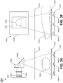
- the finger vein sensor 400 includes a sensor body 401, a finger vein pattern sensing surface 405, and an infrared light-emitting diode (LED) 409.
- the infrared light-emitting diode (LED) 409 irradiates infrared light on a finger 407 and generates finger vein pattern on the finger vein pattern sensing surface 405.
- the finger vein pattern sensing surface 405 captures the finger vein pattern for user authentication.
- the finger vein pattern sensing surface 405 is relatively small compared to the size of the finger 407.
- the finger 407 often touches the finger vein pattern sensing surface 405, and any contamination on the surface of the finger 407 may distort the finger vein pattern of the finger 407 captured, which may cause authentication errors. Additionally, the sensor body 401 defines a small space 403 above the finger vein pattern sensing surface 405. If the space 403 has water on it, the finger vein sensor 400 will fail. Therefore, the conventional finger vein sensors are widely used only in indoor applications.
- the present disclosure relates to a finger vein sensor.
- the finger vein sensor includes: an image sensor, and an infrared light source.
- the image sensor captures at least one infrared image of finger vein pattern of a finger of a target human.
- the image sensor faces down in a vertical direction and is positioned at the top of the finger vein sensor.
- the infrared light source may include includes a predetermined number of infrared light-emitting diodes (LED), a predetermined number of infrared light bulbs, and/or any other infrared light sources.
- the infrared LED and the infrared light bulbs may be arranged in one or more rows and one or more columns and positioned at the bottom of the finger vein sensor.
- the finger is positioned between the infrared light source and the image sensor.
- the infrared light from the infrared light source irradiates the finger vertically from the bottom to generate the infrared image of finger vein pattern of the finger on the image sensor, and the image sensor captures the infrared image of finger vein pattern of the finger.
- the present disclosure relates to a finger vein sensor.
- the finger vein sensor includes: an image sensor, an infrared light source, and an optical reflector.
- the image sensor captures at least one infrared image of finger vein pattern of a finger of a target human.
- the image sensor faces the target human in a horizontal direction and is positioned at the top of the finger vein sensor.
- the infrared light source includes a predetermined number of infrared light-emitting diodes (LED), a predetermined number of infrared light bulbs, and/or any other infrared light sources.
- the infrared LED and the infrared light bulbs may be arranged in one or more rows and one or more columns and positioned at the bottom of the finger vein sensor.
- the optical reflector includes a reflecting mirror, a triangular reflecting glass, or any other optical reflecting devices.
- the optical reflector is positioned between the image sensor and the infrared light source for reflecting the vertically oriented infrared image of finger vein pattern of the finger to the horizontally oriented image sensor.
- the finger is positioned between the infrared light source and the image sensor, the infrared light from the infrared light source irradiates the finger vertically from the bottom to generate the infrared image of finger vein pattern of the finger in a vertical direction, and the infrared image of finger vein pattern of the finger is reflected by the optical reflector and captured by the horizontally oriented image sensor.
- the present disclosure relates to a finger vein sensor.
- the finger vein sensor includes: an image sensor, an infrared light source, and an optical reflector.
- the image sensor captures at least one infrared image of finger vein pattern of a finger of a target human.
- the image sensor is positioned on the top right side of the finger vein sensor facing the center of the finger vein sensor in a horizontal direction.
- the image sensor is positioned on the top left side of the finger vein sensor facing the center of the finger vein sensor in a horizontal direction.
- the infrared light source includes a predetermined number of infrared light-emitting diodes (LED), a predetermined number of infrared light bulbs, and/or any other infrared light sources.
- the infrared LED and the infrared light bulbs may be arranged in one or more rows and one or more columns and positioned at the bottom of the finger vein sensor.
- the optical reflector includes a reflecting mirror, a triangular reflecting glass, or any other optical reflecting devices. The optical reflector is positioned between the image sensor and the infrared light source for reflecting the vertically oriented infrared image of finger vein pattern of the finger to the horizontally oriented image sensor.
- the finger is positioned between the infrared light source and the image sensor, the infrared light from the infrared light source irradiates the finger vertically from the bottom to generate the infrared image of finger vein pattern of the finger in a vertical direction, and the infrared image of finger vein pattern of the finger is reflected by the optical reflector and captured by the horizontally oriented image sensor.
- the finger vein sensor may include a lens positioned between the finger and the image sensor, and an infrared filter positioned between the lens and the image sensor for improving quality of the infrared image of finger vein pattern of the finger.
- the finger vein sensor may also include a finger vein sensor enclosure.
- the finger vein sensor enclosure includes a lower compartment, and an upper compartment.
- the infrared light source is positioned in the lower compartment.
- the image sensor and the lens are positioned in the upper compartment.
- an upper surface of the lower compartment forms the transparent finger resting surface.
- a lower surface of the upper compartment is a transparent surface.
- phrase at least one of A, B, and C should be construed to mean a logical (A or B or C), using a non-exclusive logical OR. It should be understood that one or more steps within a method may be executed in different order (or conconventionally) without altering the principles of the present disclosure.
- the conventional finger vein sensor 400 has, among other things, following disadvantages.
- the finger vein pattern sensing surface 405 is relatively small compared to the size of the finger 407. Therefore, only a small portion of the finger vein pattern is captured for user authentication.
- the finger 407 often touches the finger vein pattern sensing surface 405, and any contamination on the surface of the finger 407 may distort the finger vein pattern of the finger 407 captured, which may cause authentication errors.
- the sensor body 401 defines a small space 403 above the finger vein pattern sensing surface 405. If the space 403 has water on it, the finger vein sensor 400 will fail.
- the present disclosure discloses several new improvements that will increase the size of the finger vein pattern images, that will eliminate authentication error caused by sensor surface contamination, and that will prevent authentication failures caused by moisture or water on the sensor surface.
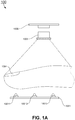
- the present disclosure relates to a finger vein sensor 100.
- the finger vein sensor 100 includes: an image sensor 1006, and an infrared light source 1001.
- the infrared light source 1001 may include includes a predetermined number of infrared light-emitting diodes (LEDs), a predetermined number of infrared light bulbs, and/or any other infrared light sources.
- the infrared light source 1001 includes a first infrared LED 10011, a second infrared LED 10012, and a third infrared LED 10013.
- the infrared LED or the infrared light bulbs may be arranged in one or more rows and one or more columns and positioned at the bottom of the finger vein sensor 100. These three LEDs as shown in FIGS.
- the infrared light source 1001 may include more than one columns of infrared LEDs (not shown in FIGS. 1A and 1B ). Such infrared light source 1001 provides high intensity and evenly distributed infrared light to penetrate a finger 1004 of a target human and generates large size finger vein pattern images with more clarity.
- the image sensor 1006 captures at least one infrared image of finger vein pattern of the finger 1004.
- the image sensor 1006 faces down in a vertical direction and is positioned at the top of the finger vein sensor 100.
- the finger 1004 is positioned between the infrared light source 1001 and the image sensor 1006.
- the infrared light from the infrared light source 1001 irradiates the finger 1004 vertically from the bottom to generate the infrared image of finger vein pattern of the finger 1004 on the image sensor 1006, and the image sensor 1006 then captures the infrared image of finger vein pattern of the finger 1004.
- the finger vein sensor 100 may include a transparent finger resting surface 1002 for resting the finger 1004.
- This transparent finger resting surface 1002 allows the user to rest the finger 1004 on it and generates a steady finger vein pattern image at a fixed location. It prevents inconsistency when the finger 1004 moves up and down.
- the finger vein sensor 100 may also include a lens 1005.
- the lens 1005 is positioned between the finger 1004 and the image sensor 1006.
- the lens 1005 is adjusted to focus on the finger vein pattern generated above the transparent finger resting surface 1002.
- the combination of the lens 1005 and the transparent finger resting surface 1002 allows the image sensor 1006 to capture consistent finger vein pattern images and improve quality of the infrared image of finger vein pattern of the finger 1004.
- the finger vein sensor 100 may also include an infrared filter 1007.
- the infrared filter 1007 may be placed between the lens 1005 and the image sensor 1006.
- the infrared filter 1007 allows infrared lights to pass and eliminates light interference from any lights other than infrared light. Therefore, the application of the infrared filter 1007 also improves the quality of the infrared image of finger vein pattern of the finger 1004.
- the finger vein sensor 100 may also include a finger vein sensor enclosure 1003 as shown in FIG. 1B .
- the finger vein sensor enclosure 1003 includes a lower compartment, and an upper compartment.
- the infrared light source 1001 is positioned in the lower compartment and provides infrared light through the transparent finger resting surface 1002 vertically from the lower compartment.
- the lens 1005, the infrared filter 1007 and the image sensor 1006 are positioned in the upper compartment.
- a lower surface 10031 of the upper compartment is a transparent surface to allow the image sensor 1006 to capture the finger vein pattern image of the finger 1004 formed above the transparent finger resting surface 1002.
- the configuration of the finger vein sensor 100 creates larger size finger vein pattern images than the conventional finger vein sensors.
- Conventional finger vein sensor allows user to touch the image forming surface of the finger vein sensor, any contamination on the image forming surface of the finger vein sensor will be captured by the conventional vein sensor and it will cause authentication errors.
- the finger vein sensor 100 prevents such errors from happening. Any contaminations such as dirt on the surface of the finger 1004, the dirt accumulated on the transparent finger resting surface 1002, or finger prints left on the transparent finger resting surface 1002 will not be captured by the image sensor 1006.
- the water stains or water accumulated on the transparent finger resting surface 1002 will not cause any authentication errors because the water will be transparent and will not distort the finger vein pattern of the finger 1004.
- the image sensor 1006 should have sufficient distance from the finger 1004 resting on the transparent finger resting surface 1002 because of the straight infrared light path from the bottom to the top of the finger vein sensor enclosure 1003. This may cause the finger vein sensor enclosure 1003 to become tall. In order to shorten the height of the finger vein sensor enclosure 1003, a few more exemplary embodiments of finger vein sensors are described as following. In certain embodiments, the straight infrared light path from the bottom to the top of the finger vein sensor enclosure 1003 may be reflected by an optical reflector to become a horizontal infrared light path.
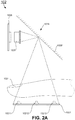
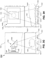
- the present disclosure relates to a finger vein sensor 102.
- the finger vein sensor 102 includes: an image sensor 1026, an infrared light source 1021, and an optical reflector 1028.
- the infrared light source 1021 may include includes a predetermined number of infrared light-emitting diodes (LEDs), a predetermined number of infrared light bulbs, and/or any other infrared light sources. As shown in the side view of the finger vein sensor 102, the infrared light source 1021 includes a first infrared LED 10211, a second infrared LED 10212, and a third infrared LED 10213. The infrared LED or the infrared light bulbs may be arranged in one or more rows and one or more columns and positioned at the bottom of the finger vein sensor 102. These three LEDs as shown in FIGS.
- LEDs infrared light-emitting diodes
- the infrared light source 1021 may include more than one columns of infrared LEDs (not shown in FIGS. 2A through 2D ).
- Such infrared light source 1021 provides high intensity and evenly distributed infrared light to penetrate a finger 1024 of a target human and generates large size finger vein pattern images with more clarity.
- the image sensor 1026 captures at least one infrared image of finger vein pattern of the finger 1024.
- the image sensor 1026 faces the target human in a horizontal direction and is positioned at the top of the finger vein sensor 102.
- the finger 1024 is positioned between the infrared light source 1021 and the image sensor 1026.
- the infrared light from the infrared light source 1021 irradiates the finger 1024 vertically from the bottom to generate the infrared image of finger vein pattern of the finger 1024.
- the optical reflector 1028 includes a reflecting mirror 10281 as shown in FIGS. 2A and 2B , a triangular reflecting glass 10282 as shown in FIGS.
- the optical reflector 1028 is positioned between the image sensor 1026 and the infrared light source 1021 for reflecting the vertically oriented infrared image of finger vein pattern of the finger 1024 to the horizontally oriented image sensor 1026.
- the finger 1024 is positioned between the infrared light source 1021 and the image sensor 1026, the infrared light from the infrared light source 1021 irradiates the finger 1024 vertically from the bottom to generate the infrared image of finger vein pattern of the finger 1024 in a vertical direction, and the infrared image of finger vein pattern of the finger 1024 is reflected by the optical reflector 1028 and captured by the horizontally oriented image sensor 1026.
- the finger vein sensor 102 may include a transparent finger resting surface 1022 for resting the finger 1024.
- This transparent finger resting surface 1022 allows the user to rest the finger 1024 on it and generates a steady finger vein pattern image at a fixed location. It prevents inconsistency when the finger 1024 moves up and down.
- the finger vein sensor 102 may also include a lens 1025.
- the lens 1025 is positioned between the finger 1024 and the image sensor 1026.
- the lens 1025 is adjusted to focus on the finger vein pattern generated above the transparent finger resting surface 1022.
- the combination of the lens 1025 and the transparent finger resting surface 1022 allows the image sensor 1026 to capture consistent finger vein pattern images and improve quality of the infrared image of finger vein pattern of the finger 1024.
- the finger vein sensor 102 may also include an infrared filter 1027.
- the infrared filter 1027 may be placed between the lens 1025 and the image sensor 1026.
- the infrared filter 1027 allows infrared lights to pass and eliminates light interference from any lights other than infrared light. Therefore, the application of the infrared filter 1027 also improves the quality of the infrared image of finger vein pattern of the finger 1024.
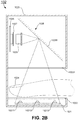
- the finger vein sensor 102 may also include a finger vein sensor enclosure 1023 as shown in FIGS. 2B and 2D .
- the finger vein sensor enclosure 1023 includes a lower compartment, and an upper compartment.
- the infrared light source 1021 is positioned in the lower compartment and provides infrared light through the transparent finger resting surface 1022 vertically from the lower compartment.
- the lens 1025, the infrared filter 1027 and the image sensor 1026 are positioned horizontally in the upper compartment.
- a lower surface 10231 of the upper compartment is a transparent surface to allow the image sensor 1026 to capture the finger vein pattern image of the finger 1024 formed above the transparent finger resting surface 1022.
- the vertical finger vein pattern image of the finger 1024 is reflected by the optical reflector 1028 and turned to a horizontal finger vein pattern image of the finger 1024 to be captured by the horizontally oriented image sensor 1026.
- the vertically generated finger vein pattern of the finger 1024 may be reflected by the optical reflector 1028 and captured by the horizontally oriented image sensor 1026 positioned on either side of the finger vein sensor 102.
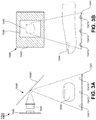
- the present disclosure relates to a finger vein sensor 104.
- the finger vein sensor 104 includes: an image sensor 1046, an infrared light source 1041, and an optical reflector 1048.
- the image sensor 1046 captures at least one infrared image of finger vein pattern of a finger 1044 of a target human.
- the image sensor 1046 is positioned on the top right side of the finger vein sensor 104 facing the center of the finger vein sensor 104 in a horizontal direction. In another embodiment, the image sensor 1046 is positioned on the top left side of the finger vein sensor 104 facing the center of the finger vein sensor 104 in a horizontal direction.
- the infrared light source 1041 may include includes a predetermined number of infrared light-emitting diodes (LEDs), a predetermined number of infrared light bulbs, and/or any other infrared light sources.
- the infrared light source 1041 includes a first infrared LED 10411, a second infrared LED 10412, and a third infrared LED 10413.
- the infrared light source 1041 includes the third infrared LED 10413, a fourth infrared LED 10414, and a fifth infrared LED 10415.
- the infrared LED or the infrared light bulbs may be arranged in three rows and three columns and positioned at the bottom of the finger vein sensor 104.
- Such infrared light source 1041 provides high intensity and evenly distributed infrared light to penetrate the finger 1044 of the target human and generates large size finger vein pattern images with more clarity.
- the optical reflector 1048 includes a reflecting mirror 10481, as shown in FIGS. 3A through 3D , a triangular reflecting glass 10482, as shown in FIGS. 3E through 3H , or any other optical reflecting devices (not shown in FIGS. 3A through 3H ).
- the optical reflector 1048 is positioned between the image sensor 1046 and the infrared light source 1041 for reflecting the vertically oriented infrared image of finger vein pattern of the finger 1044 to the horizontally oriented image sensor 1046.
- the finger 1044 is positioned between the infrared light source 1041 and the image sensor 1046, the infrared light from the infrared light source 1041 irradiates the finger 1044 vertically from the bottom to generate the infrared image of finger vein pattern of the finger 1044 in a vertical direction, and the vertically oriented infrared image of finger vein pattern of the finger 1044 is reflected by the optical reflector 1048 and captured by the horizontally oriented image sensor 1046.
- the finger vein sensor 104 may include a transparent finger resting surface 1042 for resting the finger 1044.
- This transparent finger resting surface 1042 allows the user to rest the finger 1044 on it and generates a steady finger vein pattern image at a fixed location. It prevents inconsistency when the finger 1044 moves up and down.
- the finger vein sensor 104 may also include a lens 1045.
- the lens 1045 is positioned between the finger 1044 and the image sensor 1046.
- the lens 1045 is adjusted to focus on the finger vein pattern generated above the transparent finger resting surface 1042.
- the combination of the lens 1045 and the transparent finger resting surface 1042 allows the image sensor 1046 to capture consistent finger vein pattern images and improve quality of the infrared image of finger vein pattern of the finger 1044.
- the finger vein sensor 104 may also include an infrared filter 1047.
- the infrared filter 1047 may be placed between the lens 1045 and the image sensor 1046.
- the infrared filter 1047 allows infrared lights to pass and eliminates light interference from any lights other than infrared light. Therefore, the application of the infrared filter 1047 also improves the quality of the infrared image of finger vein pattern of the finger 1044.
- the finger vein sensor 104 may also include a finger vein sensor enclosure 1043 as shown in FIGS. 3C, 3D , 3G, and 3H .
- the finger vein sensor enclosure 1043 includes a lower compartment, and an upper compartment.
- the infrared light source 1041 is positioned in the lower compartment and provides infrared light through the transparent finger resting surface 1042 vertically from the lower compartment.
- the lens 1045, the infrared filter 1047 and the image sensor 1046 are positioned horizontally in the upper compartment.
- a lower surface 10431 of the upper compartment is a transparent surface to allow the image sensor 1046 to capture the finger vein pattern image of the finger 1044 formed above the transparent finger resting surface 1042.
- the vertical finger vein pattern image of the finger 1044 is reflected by the optical reflector 1048 and turned to a horizontal finger vein pattern image of the finger 1044 to be captured by the horizontally oriented image sensor 1046.
Landscapes
- Engineering & Computer Science (AREA)
- Physics & Mathematics (AREA)
- General Physics & Mathematics (AREA)
- Multimedia (AREA)
- Theoretical Computer Science (AREA)
- Human Computer Interaction (AREA)
- Health & Medical Sciences (AREA)
- General Health & Medical Sciences (AREA)
- Vascular Medicine (AREA)
- Optics & Photonics (AREA)
- Measurement Of The Respiration, Hearing Ability, Form, And Blood Characteristics Of Living Organisms (AREA)
- Image Input (AREA)
Applications Claiming Priority (2)
| Application Number | Priority Date | Filing Date | Title |
|---|---|---|---|
| CN201710648612 | 2017-08-01 | ||
| PCT/CN2017/109780 WO2019024306A1 (zh) | 2017-08-01 | 2017-11-07 | 手指静脉图像采集装置 |
Publications (4)
| Publication Number | Publication Date |
|---|---|
| EP3663964A1 true EP3663964A1 (de) | 2020-06-10 |
| EP3663964A4 EP3663964A4 (de) | 2021-05-05 |
| EP3663964C0 EP3663964C0 (de) | 2026-02-25 |
| EP3663964B1 EP3663964B1 (de) | 2026-02-25 |
Family
ID=65232233
Family Applications (1)
| Application Number | Title | Priority Date | Filing Date |
|---|---|---|---|
| EP17920381.5A Active EP3663964B1 (de) | 2017-08-01 | 2017-11-07 | Verfahren zur aufnahme von fingervenenbildern |
Country Status (8)
| Country | Link |
|---|---|
| US (2) | US20200151480A1 (de) |
| EP (1) | EP3663964B1 (de) |
| JP (1) | JP2020529695A (de) |
| KR (1) | KR20200035954A (de) |
| CN (5) | CN109791606A (de) |
| MY (1) | MY204073A (de) |
| SG (1) | SG11202000573VA (de) |
| WO (5) | WO2019024306A1 (de) |
Families Citing this family (12)
| Publication number | Priority date | Publication date | Assignee | Title |
|---|---|---|---|---|
| CN111767758B (zh) * | 2019-04-01 | 2026-03-24 | 恩智浦美国有限公司 | 手指静脉识别系统 |
| CN110175500B (zh) * | 2019-04-03 | 2024-01-19 | 平安科技(深圳)有限公司 | 指静脉比对方法、装置、计算机设备及存储介质 |
| CN109977926A (zh) * | 2019-04-23 | 2019-07-05 | 珠海格力电器股份有限公司 | 一种指静脉识别装置、智能门锁及智能开锁方法 |
| CN110688932B (zh) * | 2019-09-20 | 2025-01-24 | 威海华菱光电股份有限公司 | 静脉识别方法和装置 |
| CN111339911B (zh) * | 2020-02-24 | 2023-07-04 | 浙江大华技术股份有限公司 | 一种手指特征识别装置 |
| CN111563475A (zh) * | 2020-05-18 | 2020-08-21 | 广州微盾科技股份有限公司 | 自适应平面式静脉采集设备、方法及存储介质 |
| JP2022014681A (ja) * | 2020-07-07 | 2022-01-20 | インターマン株式会社 | 感染防止機能付き生体認証装置 |
| CN112101332B (zh) * | 2020-11-23 | 2021-02-19 | 北京圣点云信息技术有限公司 | 一种基于3d指静脉的特征提取和比对方法及装置 |
| CN112883356B (zh) * | 2021-03-31 | 2024-04-23 | 中国工商银行股份有限公司 | 一种身份认证方法、装置及设备 |
| KR102894568B1 (ko) * | 2021-06-10 | 2025-12-03 | 에코스솔루션(주) | 비접촉 생체 인증 장치 |
| CN113780236B (zh) * | 2021-09-26 | 2025-04-11 | 盛视科技股份有限公司 | 静脉图像采集方法、采集系统及采集装置 |
| EP4526787A1 (de) * | 2022-05-20 | 2025-03-26 | Advanced Elemental Technologies, Inc. | Systeme und verfahren für eine verbundene computerressource und ereignis-/aktivitätsidentifikationsinformationsinfrastruktur mit biometrischer identifizierung von menschen nahe vorhanden oder vorhanden |
Family Cites Families (53)
| Publication number | Priority date | Publication date | Assignee | Title |
|---|---|---|---|---|
| JPH06176137A (ja) * | 1992-12-10 | 1994-06-24 | Fujitsu Ltd | 指紋像入力装置 |
| US5737439A (en) * | 1996-10-29 | 1998-04-07 | Smarttouch, Llc. | Anti-fraud biometric scanner that accurately detects blood flow |
| US8384885B2 (en) * | 2000-09-20 | 2013-02-26 | Hitachi, Ltd. | Personal identification system |
| JP2002092616A (ja) * | 2000-09-20 | 2002-03-29 | Hitachi Ltd | 個人認証装置 |
| JP4258393B2 (ja) * | 2003-03-13 | 2009-04-30 | 三菱電機株式会社 | 個人識別装置および指紋画像撮像装置、指紋画像取得方法 |
| JP4207717B2 (ja) * | 2003-08-26 | 2009-01-14 | 株式会社日立製作所 | 個人認証装置 |
| JP4671811B2 (ja) * | 2004-11-05 | 2011-04-20 | 日立オートモティブシステムズ株式会社 | 指認証装置 |
| JP2006326176A (ja) * | 2005-05-30 | 2006-12-07 | Mitsubishi Electric Corp | 指紋照合装置 |
| JP4692174B2 (ja) * | 2005-09-14 | 2011-06-01 | 株式会社日立製作所 | 個人認証装置及びドア開閉システム |
| CN101004789B (zh) * | 2006-01-17 | 2010-05-12 | 郭岳衡 | 手指静脉图像识别方法 |
| JP4952026B2 (ja) * | 2006-03-31 | 2012-06-13 | 株式会社日立製作所 | 生体情報認証装置および認証方法 |
| JP4389911B2 (ja) * | 2006-08-30 | 2009-12-24 | パナソニック電工株式会社 | 指紋像入力装置 |
| US20080317293A1 (en) * | 2007-06-22 | 2008-12-25 | Soichi Sakurai | Finger vein authentication apparatus and information processing apparatus |
| JP5034713B2 (ja) * | 2007-06-28 | 2012-09-26 | 株式会社日立製作所 | 指静脈認証装置および情報処理装置 |
| JP5151396B2 (ja) * | 2007-10-29 | 2013-02-27 | 株式会社日立製作所 | 指静脈認証装置 |
| JP2010090677A (ja) * | 2008-10-10 | 2010-04-22 | Hitachi Ltd | 入退域照合システム、入退域照合方法、およびそのプログラム |
| KR101084894B1 (ko) * | 2009-09-16 | 2011-11-17 | 삼성전기주식회사 | 전반사를 이용한 정맥 인증 장치 |
| JP2011203792A (ja) * | 2010-03-24 | 2011-10-13 | Hitachi Displays Ltd | 撮像装置 |
| TWI599964B (zh) * | 2010-09-03 | 2017-09-21 | 國立台灣科技大學 | 手指靜脈辨識系統與方法 |
| CN201845344U (zh) * | 2010-11-12 | 2011-05-25 | 中国船舶重工集团公司第七一○研究所 | 手指静脉图像采集识别装置的手指安放器 |
| CN202058176U (zh) * | 2011-05-20 | 2011-11-30 | 洛阳师范学院 | 一种嵌入式手指静脉识别装置 |
| CN202486801U (zh) * | 2012-02-13 | 2012-10-10 | 深圳市中控生物识别技术有限公司 | 一种手指静脉采集装置 |
| JP5854245B2 (ja) * | 2012-03-27 | 2016-02-09 | 日本電気株式会社 | 認証装置、認証用プリズム体及び認証方法 |
| CN102894960A (zh) * | 2012-08-29 | 2013-01-30 | 北京理工大学 | 透射式手背静脉三维红外成像仪 |
| CN103116741A (zh) * | 2013-01-28 | 2013-05-22 | 天津理工大学 | 手掌静脉与手掌纹融合图像的采集识别系统 |
| CN103310517A (zh) * | 2013-06-25 | 2013-09-18 | 奇瑞汽车股份有限公司 | 一种门锁装置 |
| JP2015088040A (ja) * | 2013-10-31 | 2015-05-07 | マネージメントサービス株式会社 | 認証装置、認証方法、及びプログラム |
| CN103679878A (zh) * | 2013-11-30 | 2014-03-26 | 成都科泰地理信息技术有限公司 | 一种基于手指静脉识别的门禁系统 |
| CN103839052B (zh) * | 2014-03-05 | 2015-12-09 | 中山微盾信息科技有限公司 | 一种手指静脉识别装置及其实现方法 |
| JP6355371B2 (ja) * | 2014-03-17 | 2018-07-11 | 株式会社 日立産業制御ソリューションズ | 個人認証装置および指静脈認証装置 |
| CN105303128B (zh) * | 2014-07-31 | 2018-09-11 | 中国电信股份有限公司 | 一种防止未经授权使用移动终端的方法和移动终端 |
| CN104598884A (zh) * | 2015-01-20 | 2015-05-06 | 深圳市维亿魄科技有限公司 | 人体手指静脉识别装置 |
| CN105760810B (zh) * | 2015-02-10 | 2021-11-19 | 公安部第一研究所 | 透射式三维指静脉数据采集装置 |
| US9558392B2 (en) * | 2015-02-12 | 2017-01-31 | Korecen Co., Ltd. | Finger vein authentication system |
| CN104636731B (zh) * | 2015-02-12 | 2017-03-22 | 张丽琴 | 一种采用手指静脉识别与腕部静脉识别、指甲识别相结合的认证装置 |
| CN105989340A (zh) * | 2015-02-17 | 2016-10-05 | 上海箩箕技术有限公司 | 静脉识别设备的光学系统 |
| CN204680031U (zh) * | 2015-03-11 | 2015-09-30 | 识益生物科技(北京)有限公司 | 一种指静脉识别模块及具有其的装置 |
| CN204557512U (zh) * | 2015-03-25 | 2015-08-12 | 浙江大学 | 一种具有高识别度的手指静脉图像采集系统 |
| JP2016224692A (ja) * | 2015-05-29 | 2016-12-28 | 日立オムロンターミナルソリューションズ株式会社 | 指静脈認証装置 |
| CN204856535U (zh) * | 2015-07-19 | 2015-12-09 | 厦门通元微智能科技有限公司 | 一种透射式的手指静脉识别图像采集装置 |
| KR102570637B1 (ko) * | 2015-08-27 | 2023-08-25 | 광주과학기술원 | 지정맥 인식 장치 및 지정맥 인식 방법 |
| CN205354052U (zh) * | 2015-11-24 | 2016-06-29 | 秦皇岛鸿大科技开发有限公司 | 近红外指静脉图像采集系统 |
| CN106778446A (zh) * | 2015-11-24 | 2017-05-31 | 秦皇岛鸿大科技开发有限公司 | 一种近红外指静脉图像采集系统 |
| CN105608770B (zh) * | 2015-12-22 | 2017-10-27 | 成都比善科技开发有限公司 | 一种电子锁及其开锁方法 |
| JPWO2017115512A1 (ja) * | 2015-12-28 | 2018-09-20 | シャープ株式会社 | 撮像装置及び生体認証装置 |
| CN105678233B (zh) * | 2015-12-30 | 2020-05-19 | 北京眼神智能科技有限公司 | 基于指纹与指静脉的复合识别方法、装置及系统 |
| CN106022210A (zh) * | 2016-05-04 | 2016-10-12 | 成都指码科技有限公司 | 一种静脉轮廓三维点云匹配的身份识别方法及装置 |
| CN205845134U (zh) * | 2016-06-29 | 2016-12-28 | 西安金麦电子科技有限公司 | 一种智能锁 |
| CN205983504U (zh) * | 2016-07-07 | 2017-02-22 | 山西圣点世纪科技股份有限公司 | 一种自适应调整光强的指静脉图像采集装置 |
| CN106340096B (zh) * | 2016-08-29 | 2018-06-26 | 神思电子技术股份有限公司 | 一种基于指纹指静脉识别智能锁具的识别装置和方法 |
| CN106960194A (zh) * | 2017-03-24 | 2017-07-18 | 徐晨 | 一种静脉识别装置 |
| CN106919941B (zh) * | 2017-04-26 | 2018-10-09 | 华南理工大学 | 一种三维手指静脉识别方法及系统 |
| CN107665345A (zh) * | 2017-11-14 | 2018-02-06 | 南京东屋电气有限公司 | 手指静脉图像采集装置以及智能锁 |
-
2017
- 2017-11-07 WO PCT/CN2017/109780 patent/WO2019024306A1/zh not_active Ceased
- 2017-11-07 SG SG11202000573VA patent/SG11202000573VA/en unknown
- 2017-11-07 KR KR1020207003187A patent/KR20200035954A/ko not_active Ceased
- 2017-11-07 JP JP2020528502A patent/JP2020529695A/ja active Pending
- 2017-11-07 MY MYPI2020000234A patent/MY204073A/en unknown
- 2017-11-07 EP EP17920381.5A patent/EP3663964B1/de active Active
- 2017-11-07 CN CN201780059886.9A patent/CN109791606A/zh active Pending
- 2017-11-07 US US15/572,541 patent/US20200151480A1/en not_active Abandoned
- 2017-11-14 CN CN201780059860.4A patent/CN109844755A/zh active Pending
- 2017-11-14 WO PCT/CN2017/110943 patent/WO2019024321A1/zh not_active Ceased
- 2017-11-14 CN CN201780059884.XA patent/CN109844821A/zh active Pending
- 2017-11-14 WO PCT/CN2017/110939 patent/WO2019024318A1/zh not_active Ceased
- 2017-11-14 CN CN201780059861.9A patent/CN109844756A/zh active Pending
- 2017-11-14 WO PCT/CN2017/110941 patent/WO2019024319A1/zh not_active Ceased
- 2017-11-14 WO PCT/CN2017/110942 patent/WO2019024320A1/zh not_active Ceased
- 2017-11-14 US US16/326,368 patent/US20210287025A1/en not_active Abandoned
- 2017-11-14 CN CN201780060859.3A patent/CN109844758B/zh active Active
Also Published As
| Publication number | Publication date |
|---|---|
| CN109844758A (zh) | 2019-06-04 |
| WO2019024306A1 (zh) | 2019-02-07 |
| WO2019024321A1 (zh) | 2019-02-07 |
| WO2019024319A1 (zh) | 2019-02-07 |
| CN109791606A (zh) | 2019-05-21 |
| US20210287025A1 (en) | 2021-09-16 |
| EP3663964C0 (de) | 2026-02-25 |
| CN109844755A (zh) | 2019-06-04 |
| US20200151480A1 (en) | 2020-05-14 |
| CN109844821A (zh) | 2019-06-04 |
| KR20200035954A (ko) | 2020-04-06 |
| JP2020529695A (ja) | 2020-10-08 |
| CN109844758B (zh) | 2024-08-30 |
| CN109844756A (zh) | 2019-06-04 |
| SG11202000573VA (en) | 2020-02-27 |
| WO2019024318A1 (zh) | 2019-02-07 |
| EP3663964B1 (de) | 2026-02-25 |
| MY204073A (en) | 2024-08-06 |
| WO2019024320A1 (zh) | 2019-02-07 |
| EP3663964A4 (de) | 2021-05-05 |
Similar Documents
| Publication | Publication Date | Title |
|---|---|---|
| EP3663964A1 (de) | Verfahren zur aufnahme von fingervenenbildern | |
| US7593593B2 (en) | Method and system for reducing effects of undesired signals in an infrared imaging system | |
| JP6484072B2 (ja) | 物体検出装置 | |
| US10962790B2 (en) | Depth measurement using a pulsed structured light projector | |
| US20190025849A1 (en) | Robot for automated image acquisition | |
| US20190072771A1 (en) | Depth measurement using multiple pulsed structured light projectors | |
| JPWO2017125984A1 (ja) | 空中表示装置 | |
| US20130083252A1 (en) | Gesture recognition capable picture video frame | |
| CN103299259A (zh) | 检测装置、输入装置、投影机以及电子设备 | |
| CN104029008A (zh) | 利用视觉系统在遮挡环境下对齐两工件的系统与方法 | |
| JP5138116B2 (ja) | 情報取得装置および物体検出装置 | |
| JP2014122789A (ja) | 情報取得装置、投射装置および物体検出装置 | |
| US8982101B2 (en) | Optical touch system and optical touch-position detection method | |
| US20140240228A1 (en) | User interface display device | |
| CN209496381U (zh) | 光学指纹识别模组和终端设备 | |
| US20140306934A1 (en) | Optical touch panel system, optical apparatus and positioning method thereof | |
| US9489085B2 (en) | Optical touch panel system and positioning method thereof | |
| CN106599930B (zh) | 虚拟现实空间定位特征点筛选方法 | |
| US20130106786A1 (en) | Handwriting System and Sensing Method Thereof | |
| US20210166000A1 (en) | Monitoring system and monitoring method | |
| JP6620320B2 (ja) | 読取装置 | |
| US20230196823A1 (en) | Finger vein sensors | |
| US20240005696A1 (en) | Finger vein sensors and methods of using the same | |
| WO2014083921A1 (ja) | 欠陥判定装置、対応関係情報作成装置、欠陥判定方法、および対応関係情報作成方法 | |
| KR200482563Y1 (ko) | 홍채 촬영에 최적화된 광학필터를 구비한 홍채 인식 장치 |
Legal Events
| Date | Code | Title | Description |
|---|---|---|---|
| STAA | Information on the status of an ep patent application or granted ep patent |
Free format text: STATUS: THE INTERNATIONAL PUBLICATION HAS BEEN MADE |
|
| PUAI | Public reference made under article 153(3) epc to a published international application that has entered the european phase |
Free format text: ORIGINAL CODE: 0009012 |
|
| STAA | Information on the status of an ep patent application or granted ep patent |
Free format text: STATUS: REQUEST FOR EXAMINATION WAS MADE |
|
| 17P | Request for examination filed |
Effective date: 20200121 |
|
| AK | Designated contracting states |
Kind code of ref document: A1 Designated state(s): AL AT BE BG CH CY CZ DE DK EE ES FI FR GB GR HR HU IE IS IT LI LT LU LV MC MK MT NL NO PL PT RO RS SE SI SK SM TR |
|
| AX | Request for extension of the european patent |
Extension state: BA ME |
|
| DAV | Request for validation of the european patent (deleted) | ||
| DAX | Request for extension of the european patent (deleted) | ||
| A4 | Supplementary search report drawn up and despatched |
Effective date: 20210406 |
|
| RIC1 | Information provided on ipc code assigned before grant |
Ipc: G06K 9/00 20060101AFI20210329BHEP Ipc: G06K 9/20 20060101ALI20210329BHEP |
|
| STAA | Information on the status of an ep patent application or granted ep patent |
Free format text: STATUS: EXAMINATION IS IN PROGRESS |
|
| 17Q | First examination report despatched |
Effective date: 20230206 |
|
| REG | Reference to a national code |
Ref country code: DE Ref legal event code: R079 Free format text: PREVIOUS MAIN CLASS: G06K0009000000 Ipc: G06V0010143000 Ref country code: DE Ref legal event code: R079 Ref document number: 602017094085 Country of ref document: DE Free format text: PREVIOUS MAIN CLASS: G06K0009000000 Ipc: G06V0010143000 |
|
| GRAP | Despatch of communication of intention to grant a patent |
Free format text: ORIGINAL CODE: EPIDOSNIGR1 |
|
| STAA | Information on the status of an ep patent application or granted ep patent |
Free format text: STATUS: GRANT OF PATENT IS INTENDED |
|
| RIC1 | Information provided on ipc code assigned before grant |
Ipc: G06V 10/143 20220101AFI20251104BHEP |
|
| INTG | Intention to grant announced |
Effective date: 20251209 |
|
| GRAS | Grant fee paid |
Free format text: ORIGINAL CODE: EPIDOSNIGR3 |
|
| GRAA | (expected) grant |
Free format text: ORIGINAL CODE: 0009210 |
|
| STAA | Information on the status of an ep patent application or granted ep patent |
Free format text: STATUS: THE PATENT HAS BEEN GRANTED |
|
| AK | Designated contracting states |
Kind code of ref document: B1 Designated state(s): AL AT BE BG CH CY CZ DE DK EE ES FI FR GB GR HR HU IE IS IT LI LT LU LV MC MK MT NL NO PL PT RO RS SE SI SK SM TR |
|
| REG | Reference to a national code |
Ref country code: CH Ref legal event code: F10 Free format text: ST27 STATUS EVENT CODE: U-0-0-F10-F00 (AS PROVIDED BY THE NATIONAL OFFICE) Effective date: 20260225 Ref country code: GB Ref legal event code: FG4D |
|
| REG | Reference to a national code |
Ref country code: DE Ref legal event code: R096 Ref document number: 602017094085 Country of ref document: DE |
|
| REG | Reference to a national code |
Ref country code: IE Ref legal event code: FG4D |
|
| U01 | Request for unitary effect filed |
Effective date: 20260226 |
|
| U07 | Unitary effect registered |
Designated state(s): AT BE BG DE DK EE FI FR IT LT LU LV MT NL PT RO SE SI Effective date: 20260313 |