EP3663923A1 - Independent and interlocking redundancy system - Google Patents
Independent and interlocking redundancy system Download PDFInfo
- Publication number
- EP3663923A1 EP3663923A1 EP19205387.4A EP19205387A EP3663923A1 EP 3663923 A1 EP3663923 A1 EP 3663923A1 EP 19205387 A EP19205387 A EP 19205387A EP 3663923 A1 EP3663923 A1 EP 3663923A1
- Authority
- EP
- European Patent Office
- Prior art keywords
- processors
- control command
- control
- processor
- timing
- Prior art date
- Legal status (The legal status is an assumption and is not a legal conclusion. Google has not performed a legal analysis and makes no representation as to the accuracy of the status listed.)
- Granted
Links
Images

Classifications
-
- H—ELECTRICITY
- H04—ELECTRIC COMMUNICATION TECHNIQUE
- H04L—TRANSMISSION OF DIGITAL INFORMATION, e.g. TELEGRAPHIC COMMUNICATION
- H04L41/00—Arrangements for maintenance, administration or management of data switching networks, e.g. of packet switching networks
- H04L41/06—Management of faults, events, alarms or notifications
- H04L41/0654—Management of faults, events, alarms or notifications using network fault recovery
- H04L41/0668—Management of faults, events, alarms or notifications using network fault recovery by dynamic selection of recovery network elements, e.g. replacement by the most appropriate element after failure
-
- G—PHYSICS
- G06—COMPUTING OR CALCULATING; COUNTING
- G06F—ELECTRIC DIGITAL DATA PROCESSING
- G06F11/00—Error detection; Error correction; Monitoring
- G06F11/07—Responding to the occurrence of a fault, e.g. fault tolerance
- G06F11/16—Error detection or correction of the data by redundancy in hardware
- G06F11/20—Error detection or correction of the data by redundancy in hardware using active fault-masking, e.g. by switching out faulty elements or by switching in spare elements
- G06F11/202—Error detection or correction of the data by redundancy in hardware using active fault-masking, e.g. by switching out faulty elements or by switching in spare elements where processing functionality is redundant
- G06F11/2023—Failover techniques
- G06F11/2028—Failover techniques eliminating a faulty processor or activating a spare
-
- G—PHYSICS
- G06—COMPUTING OR CALCULATING; COUNTING
- G06F—ELECTRIC DIGITAL DATA PROCESSING
- G06F11/00—Error detection; Error correction; Monitoring
- G06F11/07—Responding to the occurrence of a fault, e.g. fault tolerance
- G06F11/16—Error detection or correction of the data by redundancy in hardware
- G06F11/20—Error detection or correction of the data by redundancy in hardware using active fault-masking, e.g. by switching out faulty elements or by switching in spare elements
- G06F11/202—Error detection or correction of the data by redundancy in hardware using active fault-masking, e.g. by switching out faulty elements or by switching in spare elements where processing functionality is redundant
- G06F11/2038—Error detection or correction of the data by redundancy in hardware using active fault-masking, e.g. by switching out faulty elements or by switching in spare elements where processing functionality is redundant with a single idle spare processing component
-
- G—PHYSICS
- G06—COMPUTING OR CALCULATING; COUNTING
- G06F—ELECTRIC DIGITAL DATA PROCESSING
- G06F11/00—Error detection; Error correction; Monitoring
- G06F11/07—Responding to the occurrence of a fault, e.g. fault tolerance
- G06F11/0703—Error or fault processing not based on redundancy, i.e. by taking additional measures to deal with the error or fault not making use of redundancy in operation, in hardware, or in data representation
- G06F11/0751—Error or fault detection not based on redundancy
- G06F11/0754—Error or fault detection not based on redundancy by exceeding limits
- G06F11/0757—Error or fault detection not based on redundancy by exceeding limits by exceeding a time limit, i.e. time-out, e.g. watchdogs
-
- G—PHYSICS
- G06—COMPUTING OR CALCULATING; COUNTING
- G06F—ELECTRIC DIGITAL DATA PROCESSING
- G06F11/00—Error detection; Error correction; Monitoring
- G06F11/07—Responding to the occurrence of a fault, e.g. fault tolerance
- G06F11/0796—Safety measures, i.e. ensuring safe condition in the event of error, e.g. for controlling element
-
- G—PHYSICS
- G06—COMPUTING OR CALCULATING; COUNTING
- G06F—ELECTRIC DIGITAL DATA PROCESSING
- G06F11/00—Error detection; Error correction; Monitoring
- G06F11/07—Responding to the occurrence of a fault, e.g. fault tolerance
- G06F11/16—Error detection or correction of the data by redundancy in hardware
- G06F11/1658—Data re-synchronization of a redundant component, or initial sync of replacement, additional or spare unit
-
- G—PHYSICS
- G06—COMPUTING OR CALCULATING; COUNTING
- G06F—ELECTRIC DIGITAL DATA PROCESSING
- G06F11/00—Error detection; Error correction; Monitoring
- G06F11/07—Responding to the occurrence of a fault, e.g. fault tolerance
- G06F11/16—Error detection or correction of the data by redundancy in hardware
- G06F11/20—Error detection or correction of the data by redundancy in hardware using active fault-masking, e.g. by switching out faulty elements or by switching in spare elements
- G06F11/202—Error detection or correction of the data by redundancy in hardware using active fault-masking, e.g. by switching out faulty elements or by switching in spare elements where processing functionality is redundant
- G06F11/2023—Failover techniques
- G06F11/2025—Failover techniques using centralised failover control functionality
-
- G—PHYSICS
- G06—COMPUTING OR CALCULATING; COUNTING
- G06F—ELECTRIC DIGITAL DATA PROCESSING
- G06F11/00—Error detection; Error correction; Monitoring
- G06F11/07—Responding to the occurrence of a fault, e.g. fault tolerance
- G06F11/16—Error detection or correction of the data by redundancy in hardware
- G06F11/20—Error detection or correction of the data by redundancy in hardware using active fault-masking, e.g. by switching out faulty elements or by switching in spare elements
- G06F11/202—Error detection or correction of the data by redundancy in hardware using active fault-masking, e.g. by switching out faulty elements or by switching in spare elements where processing functionality is redundant
- G06F11/2023—Failover techniques
- G06F11/2033—Failover techniques switching over of hardware resources
-
- H—ELECTRICITY
- H04—ELECTRIC COMMUNICATION TECHNIQUE
- H04L—TRANSMISSION OF DIGITAL INFORMATION, e.g. TELEGRAPHIC COMMUNICATION
- H04L67/00—Network arrangements or protocols for supporting network services or applications
- H04L67/01—Protocols
- H04L67/12—Protocols specially adapted for proprietary or special-purpose networking environments, e.g. medical networks, sensor networks, networks in vehicles or remote metering networks
Definitions
- the invention relates to a redundancy system that allows for redundancy of a system that includes multiple processors.
- a mobile body such as an aircraft
- a system that includes multiple processors.
- the aircraft is provided with such a system for controls including a flight control, allowing for redundancy of the system and thereby preventing a flight or any other operation of the aircraft from being influenced even when a malfunction occurs in one of the processors.
- Various techniques have been proposed that achieve the redundancy of the system that includes the multiple processors.
- Japanese Unexamined Patent Application Publication JP 2004-280 853 A discloses a technique of a system that includes multiple processors and a redundancy processor.
- the technique causes the redundancy processor to take over logical setting of a malfunctioning processor when any of the processors malfunctions, making it possible to continue operation without changing logical connections.
- JP H08-255 091 A also discloses a technique of a system that includes multiple processors and a redundancy processor.
- the technique compares a memory content between the multiple processors to identify a malfunctioning processor when any of the processors malfunctions, and causes the redundancy processor to copy the memory content from a non-malfunctioning processor among the multiple processors to thereby restore the system.
- An aspect of the invention provides an independent and interlocking redundancy system that includes: one or more of control targets; operation processors configured to transmit, independently from each other and by taking turns, a control command to the one or more control targets; and one or more standby processors.
- the one or more standby processors is configured to:
- Existing systems can involve a time period in which none of processors perform a control to be performed on a control target, from a timing at which a processor is malfunctioned to a timing at which a switchover is performed from the malfunctioning processor to a redundancy processor.
- the timing of the control to be performed on the control target can also be delayed, from the timing at which the processor is malfunctioned to the timing at which the switchover is performed.
- the independent and interlocking redundancy system 1 may include two operation processors 3 ⁇ and 3 ⁇ and one (or a single) standby processor 3 ⁇ to thereby control one (or a single) control target 2.
- the configuration of the independent and interlocking redundancy system 1 according to the following example embodiment is illustrative and nonlimiting.
- the independent and interlocking redundancy system 1 may include three or more operation processors, and/or may include two or more standby processors, i.e., may include multiple standby processors. In some embodiments, the independent and interlocking redundancy system 1 may control two or more control targets, i.e., may control multiple control targets.
- the control target 2 may include a controller 2a.
- the controller 2a may cause the operation processors 3 ⁇ and 3 ⁇ and the standby processor 3 ⁇ to transmit, to the controller 2a of the control target 2, parameters necessary for controlling the control target 2, to thereby allow the operation processors 3 ⁇ and 3 ⁇ and the standby processor 3 ⁇ to control the control target 2.
- control target 2 includes the controller 2a.
- data, instructions, signals, and/or other factors may be transmitted to control the control target 2.
- embodiments of the invention may employ various control schemes, depending on, for example, a type of the control target 2 and/or how the system is constructed.
- control command the parameters, the data, the instructions, the signals, and/or other factors, transmitted from the operation processors 3 ⁇ and 3 ⁇ and the standby processor 3 ⁇ to control the control target 2, are collectively referred to as a "control command”.
- a timing at which the relevant one of the operation processors and the standby processor transmits the control command to the control target may be a timing at which the transmission request is transmitted from the control target to the relevant one of the operation processors and the standby processor.
- the timing at which the relevant one of the operation processors and the standby processor transmits the control command to the control target may be a timing at which the external clock is issued.
- the timing at which the operation processors and the standby processor transmit the control command to the control target may vary depending on, for example, how the system is constructed.
- FIG. 1 is a diagram illustrating an example of a configuration of an independent and interlocking redundancy system according to an example embodiment of the invention.
- the independent and interlocking redundancy system 1 includes the control target 2, the multiple operation processors 3 ⁇ and 3 ⁇ , and the standby processor 3 ⁇ .
- the operation processors 3 ⁇ and 3 ⁇ transmit, independently from each other and by taking turns, the control command to the control target 2.
- the independent and interlocking redundancy system 1 may have a configuration in which the control target 2, the operation processors 3 ⁇ and 3 ⁇ , and the standby processor 3 ⁇ are coupled through a communication network N.
- the control target 2, the operation processors 3 ⁇ and 3 ⁇ , and the standby processor 3 ⁇ may be coupled directly without the intervention of the communication network N. Accordingly, how the control target 2, the operation processors 3 ⁇ and 3 ⁇ , and the standby processor 3 ⁇ are coupled is not limited to the coupling through the communication network N.
- control target 2 receives the control command from the communication network N, meaning that, after all, the control command is transmitted from the relevant one of the operation processors 3 ⁇ and 3 ⁇ to the control target 2.
- the control target 2 may include the controller 2a as described above.
- the controller 2a may receive the control command from the communication network N.
- the controller 2a may receive the control command from relevant one of the operation processors 3 ⁇ and 3 ⁇ through the communication network N.
- the controller 2a may control the control target 2 on the basis of the received control command.
- control target 2 may not include the controller 2a. Accordingly, any configuration may be employed as long as the control target 2 is controlled by the operation processors 3 ⁇ and 3 ⁇ .
- One or more of the operation processors 3 ⁇ and 3 ⁇ and the standby processor 3 ⁇ may be, or may include, a computer or any other arithmetic processor, for example.
- the operation processors 3 ⁇ and 3 ⁇ is provided in the independent and interlocking redundancy system 1. Further, in an example embodiment, a relevant one of the operation processors 3 ⁇ and 3 ⁇ may determine the control command, e.g., a parameter in this case, to be transmitted to the control target 2 and transmit the determined control command to the communication network N at a predetermined timing. Further, when the transmission of the control command is completed, the relevant one of the operation processors 3 ⁇ and 3 ⁇ may transmit an end signal to the communication network N.
- the control command e.g., a parameter in this case
- the operation processors 3 ⁇ and 3 ⁇ may thus individually monitor, for example, a timing at which the transmission request is transmitted from the control target or a timing of the issuance of the external clock that allows for synchronization, without making a contact with each other. On the basis of the individually-monitored timing, the operation processors 3 ⁇ and 3 ⁇ transmit the control command independently from each other.
- independent and interlocking redundancy system 1 means that the operation processors 3 ⁇ and 3 ⁇ transmit, independently from each other, the control command to the control target 2.
- the operation processors 3 ⁇ and 3 ⁇ transmit the control command to the communication network N by taking turns.
- the operation processors 3 ⁇ and 3 ⁇ transmit the control command to the control target 2 by taking turns.
- An example embodiment illustrated in FIG. 1 includes two operation processors 3 ⁇ and 3 ⁇ , whereby the operation processors 3 ⁇ and 3 ⁇ may transmit the control command alternately.
- control command may be transmitted appropriately from a relevant one of the operation processors 3 ⁇ and 3 ⁇ at each timing, as seen from the control target 2.
- the term "interlocking" of the independent and interlocking redundancy system 1 means that the operation processors 3 ⁇ and 3 ⁇ transmit the control command by taking turns to control the control target 2, as if the operation processors 3 ⁇ and 3 ⁇ are so interlocked with each other as to control the control target 2. Note that the term “interlocking” does not mean that the operation processors 3 ⁇ and 3 ⁇ make a contact with each other to perform the control.
- the operation processors are thus configured to transmit, independently from each other and by taking turns, the control command to the control target 2.
- the operation processors may transmit the control command independently from each other and by taking turns through the communication network N.
- the n-number of operation processors in the independent and interlocking redundancy system 1 may individually monitor the above-described timing, where "n" is an integer of two or more.
- the relevant one of the operation processors may refrain from determining the control command at each of timings from a first timing to an "n-1 th" timing, and may determine the control command and transmit the determined control command at an "n th" timing.
- the first timing is a timing that is subsequent to the certain timing.
- the operation processors may thus perform the above operations independently from each other, in such a manner that the timing at which each of the operation processors performs the above operation is shifted by one timing. With this configuration, the operation processors transmit the control command to the control target 2 by taking turns for each timing.
- each of the operation processors may have, in advance, input data on the number "n" of the operation processors provided in the independent and interlocking redundancy system 1.
- each of the operation processors may automatically determine the control command and transmit the determined control command at a relevant timing at which the own operation processor should perform a process.
- the operation processors transmit the control command by taking turns.
- the independent and interlocking redundancy system 1 may include two operation processors 3 ⁇ and 3 ⁇ .
- the operation processors 3 ⁇ and 3 ⁇ may transmit, by taking turns, the control command at their respective timings in order of the operation processor 3 ⁇ , the operation processor 3 ⁇ , the operation processor 3 ⁇ , the operation processor 3 ⁇ , and so forth.
- the operation processors 3 ⁇ and 3 ⁇ may transmit the control command at their respective timings in an alternate fashion.
- the operation processors A, B, and C may transmit, by taking turns, the control command at their respective timings in order of the operation processor A, the operation processor B, the operation processor C, the operation processor A, the operation processor B, the operation processor C, and so forth.
- the operation processors may individually monitor the above-described timing, and may perform operations including the determination and the transmission of the control command on the basis of the individually-monitored timing.
- the independent and interlocking redundancy system 1 does not cause another operation processor out of the operation processors to take over a process that has been performed by the malfunctioned operation processor.
- the operation processors may monotonously continue their respective processes that have been performed so far.
- the independent and interlocking redundancy system 1 may cause the standby processor 3 ⁇ to take over the process that has been performed by the malfunctioned operation processor.
- the malfunctioning operation processor may be repaired or replaced by a different operation processor, following which the process may be returned and processed by the repaired or the replaced operation processor.
- the standby processor 3 ⁇ that has taken over the process may be used continuously thereafter as the operation processor.
- the standby processor 3 ⁇ makes a transition from a standby state to a warming-up state when one of the operation processors 3 ⁇ and 3 ⁇ malfunctions (e.g., when the operation processor 3 ⁇ malfunctions).
- the non-malfunctioning one of the operation processors 3 ⁇ and 3 ⁇ (e.g., the operation processor 3 ⁇ ) transmits, to the control target 2, the control command that is the same as the control command transmitted to the control target 2 by the non-malfunctioning operation processor 3 ⁇ , at a timing at which the malfunctioning operation processor 3 ⁇ is supposed to transmit the control command to the control target 2.
- the standby processor 3 ⁇ may serve equally as the operation processor, and transmits the control command to the control target 2 independently from the non-malfunctioning operation processor 3 ⁇ and by taking turns with respect to the non-malfunctioning operation processor 3 ⁇ .
- the standby processor 3 ⁇ may be completely equal in configuration to each of the operation processors 3 ⁇ and 3 ⁇ . Hence, optionally, the standby processor 3 ⁇ may not have a configuration special to the standby processor 3 ⁇ .
- placing the standby processor 3 ⁇ in the standby state or in the warming-up state means that the standby processor 3 ⁇ is in the standby state or in the warming-up state with regard to the controlling of the control target 2.
- the standby processor 3 ⁇ may perform any other process other than the controlling of the control target 2 or may stand by without performing any other process, during a period in which the standby processor 3 ⁇ is placed in the standby state or in the warming-up state.
- the standby processor 3 ⁇ may monitor the above-described timing as with the operation processors 3 ⁇ and 3 ⁇ . Further, the standby processor 3 ⁇ may monitor whether the end signal is transmitted from the communication network N for each timing. In this case, optionally, it is not necessary for the standby processor 3 ⁇ to recognize which of the operation processors 3 ⁇ and 3 ⁇ has transmitted the end signal.
- the standby processor 3 ⁇ may determine that any of the operation processors malfunctions, in a case where, despite the arrival of timing, the corresponding end signal is not transmitted from the communication network N. When determining that any of the operation processors malfunctions, the standby processor 3 ⁇ makes the transition from the standby state to the warming-up state.
- the standby processor 3 ⁇ determines that one of the operation processors malfunctions, optionally, it is not necessary for the standby processor 3 ⁇ to recognize which of the operation processors 3 ⁇ and 3 ⁇ malfunctions.
- the standby processor 3 ⁇ may take over the malfunctioning operation processor (e.g., the operation processors 3 ⁇ ), and transmits the control command to the communication network N, i.e., to the control target 2, at the timing at which the malfunctioning operation processor 3 ⁇ is supposed to transmit the control command.
- the malfunctioning operation processor e.g., the operation processors 3 ⁇
- the standby processor 3 ⁇ may refrain from determining the control command at a timing (at which timing the operation processor 3 ⁇ transmits the control command) that is subsequent to the timing at which no end signal is transmitted from the communication network N, and may determine and transmit the control command at a timing that is subsequent to the timing at which the operation processor 3 ⁇ transmits the control command.
- the operation processor 3 ⁇ and the standby processor 3 ⁇ may transmit the control command to the control target 2 at the respective alternate timings.
- the standby processor 3 ⁇ may generally refrain from determining the control command at each of timings from a first timing to an "n-1 th" timing (the operation processors may transmit the control command at each of those timings), and determine the control command and transmit the determined control command at an "n th" timing.
- the first timing is a timing that is subsequent to the timing at which no end signal is transmitted, i.e., the timing at which any of the operation processors is malfunctioned.
- the standby processor 3 ⁇ can fail to determine the control command or a parameter in this case, or can fail to determine an appropriate control command.
- the standby processor 3 ⁇ transmits, to the control target 2, the control command that is the same as the control command transmitted to the control target 2 by the non-malfunctioning operation processor 3 ⁇ , at the timing at which the malfunctioning operation processor 3 ⁇ is supposed to transmit the control command, i.e., at the "n th" timing described above.
- the standby processor 3 ⁇ may temporarily cause a memory to store that control command.
- the standby processor 3 ⁇ may read out the control command from the memory (i.e., the control command that is the same as the control command transmitted by the operation processor 3 ⁇ ), and may transmit the read-out control command to the control target 2 through the communication network N.
- the operation processor 3 ⁇ and the standby processor 3 ⁇ may transmit the control commands (e.g., parameters) of 1, 1, 3, 3, 5, and so forth alternately at their respective timings, when, in the same situation, the operation processor 3 ⁇ malfunctions thereafter and the standby processor 3 ⁇ is still in the warming-up state.
- the independent and interlocking redundancy system 1 thus can involve repeated transmission of the same control command (e.g., the same parameter) to the control target 2 or can involve an increase of the control command (e.g., parameter) by 2, even in a case where the control command (e.g., the parameter) is supposed to increase by 1 (one) for each timing.
- the independent and interlocking redundancy system 1 leaves rooms for improvement in terms of making the control to be performed on the control target 2 smooth.
- the independent and interlocking redundancy system 1 at least helps to prevent an occurrence of a situation where the control command is not transmitted at a timing at which the control command is supposed to be transmitted to the control target 2 or an occurrence of a delay in transmitting the control command, making it possible to ensure that the control command is transmitted to the control target 2 at each timing.
- the independent and interlocking redundancy system 1 is able to continue performing the control to be performed on the control target 2 at an appropriate timing, without causing a situation where the control target 2 is uncontrolled by the operation processors or where the control timing is delayed even when any of the operation processors malfunctions.
- the standby processor 3 ⁇ may refrain from determining the control command at each of timings from the first timing to the "n-1 th" timing, and may temporarily cause the memory to store the control command transmitted from the communication network N at the "n-1 th" timing.
- the first timing is a timing that is subsequent to the timing at which no end signal is transmitted from the communication network N.
- the standby processor 3 ⁇ may read out the control command from the memory (i.e., the control command that is the same as the control command transmitted at the "n-1 th" timing by the non-malfunctioning operation processor) and transmit the read-out control command to the control target 2 through the communication network N at the "n th" timing, i.e., at the timing at which the standby processor 3 ⁇ transmits the control command.
- the standby processor 3 ⁇ may be able to determine the control command, or a parameter in this case, appropriately.
- the standby processor 3 ⁇ is able to determine the control command by itself, and transmit the control command independently from the non-malfunctioning operation processor 3 ⁇ and by taking turns with respect to the non-malfunctioning operation processor 3 ⁇ in an example embodiment.
- the standby processor 3 ⁇ may determine that the warm-up of the standby processor 3 ⁇ is completed, when a difference between the control command transmitted by any other operation processor 3 ⁇ (e.g., the control command stored in the memory of the standby processor 3 ⁇ ) and the control command uniquely determined by the standby processor 3 ⁇ in the warming-up state falls within a predetermined error range. In this case, the standby processor 3 ⁇ may determine that the standby processor 3 ⁇ is now able to appropriately determine the control command as with any other operation processor 3 ⁇ .
- any other operation processor 3 ⁇ e.g., the control command stored in the memory of the standby processor 3 ⁇
- the independent and interlocking redundancy system 1 is thus able to restore a state in which, even when one of the operation processors malfunctions, any other operation processor and the standby processor transmit, independently from each other and by taking turns, the control command to the control target 2 at the respective appropriate timings.
- the standby processor makes the transition from the standby state to the warming-up state when one of the operation processors malfunctions.
- the standby processor transmits, to the control target, the control command that is the same as the control command transmitted to the control target by the non-malfunctioning operation processor, at the timing at which the malfunctioning operation processor is supposed to transmit the control command to the control target.
- the standby processor may serve as the operation processor, and transmits the control command independently from the non-malfunctioning operation processor and by taking turns with respect to the non-malfunctioning operation processor.
- the independent and interlocking redundancy system 1 makes it possible to continue performing the control at an appropriate timing, without causing a situation where the control target is uncontrolled by the operation processors or where the control timing is delayed even when any of the operation processors malfunctions.
- the standby processor 3 ⁇ may perform the process without identifying which of the operation processors malfunctions. In an alternative example embodiment, the standby processor 3 ⁇ may identify which of the operation processors malfunctions.
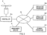
- the independent and interlocking redundancy system 1 may include a management device 4 as illustrated in FIG. 3 .
- the management device 4 may perform, for example, a process of causing the standby processor 3 ⁇ to make the transition from the standby state to the warming-up state when one of the operation processors malfunctions.
- the standby processor 3 ⁇ may perform one or more of the processes described above in accordance with the instructions given from the management device 4.
- the management device 4 may also configured to stop managing the standby processor 3 ⁇ once the warm-up of the standby processor 3 ⁇ is completed, in a case where the standby processor 3 ⁇ , having taken over the process of the malfunctioning operation processor, is to be used continuously thereafter.
- the standby processor 3 ⁇ is no longer under the management of the management device 4 after the warm-up, and may continuously perform the controlling of the control target 2 as the single independent operation processor.
- the independent and interlocking redundancy system 1 is applicable to a mobile body other than the aircraft, such as a vehicle or a vessel.
- An application of the independent and interlocking redundancy system 1 according to any embodiment of the invention is not limited to a mobile body such as the aircraft as well. Any embodiment of the invention is applicable to any system, as long as the system controls one or more control targets by the multiple processors.
- any embodiment of the invention it is possible to continue performing a control without causing a situation where the control target is uncontrolled by the processors or where a control timing is delayed even when any of the processors malfunctions in a system that includes the multiple processors.
- One or more of the operation processors 3 ⁇ and 3 ⁇ , the standby processor 3 ⁇ , and the management device 4 illustrated in FIGS. 1 to 3 is implementable by circuitry including at least one semiconductor integrated circuit such as at least one processor (e.g., a central processing unit (CPU)), at least one application specific integrated circuit (ASIC), and/or at least one field programmable gate array (FPGA).
- processors e.g., a central processing unit (CPU)
- ASIC application specific integrated circuit
- FPGA field programmable gate array
- At least one processor is configurable, by reading instructions from at least one machine readable non-transitory tangible medium, to perform all or a part of functions of any of the operation processors 3 ⁇ and 3 ⁇ , the standby processor 3 ⁇ , and the management device 4.
- a medium may take many forms, including, but not limited to, any type of magnetic medium such as a hard disk, any type of optical medium such as a CD and a DVD, any type of semiconductor memory (i.e., semiconductor circuit) such as a volatile memory and a non-volatile memory.
- the volatile memory may include a DRAM and a SRAM
- the nonvolatile memory may include a ROM and a NVRAM.
- the ASIC is an integrated circuit (IC) customized to perform
- the FPGA is an integrated circuit designed to be configured after manufacturing in order to perform, all or a part of the functions of any of the operation processors 3 ⁇ and 3 ⁇ , the standby processor 3 ⁇ , and the management device 4 illustrated in FIGS. 1 to 3 .
Landscapes
- Engineering & Computer Science (AREA)
- Theoretical Computer Science (AREA)
- Quality & Reliability (AREA)
- Physics & Mathematics (AREA)
- General Engineering & Computer Science (AREA)
- General Physics & Mathematics (AREA)
- Computer Networks & Wireless Communication (AREA)
- Signal Processing (AREA)
- Hardware Redundancy (AREA)
- Multi Processors (AREA)
- Safety Devices In Control Systems (AREA)
Abstract
Description
- The present application claims priority from Japanese Patent Application No.
2018-226190 filed on December 3, 2018 - The invention relates to a redundancy system that allows for redundancy of a system that includes multiple processors.
- A mobile body, such as an aircraft, is typically provided with a system that includes multiple processors. For example, the aircraft is provided with such a system for controls including a flight control, allowing for redundancy of the system and thereby preventing a flight or any other operation of the aircraft from being influenced even when a malfunction occurs in one of the processors.
Various techniques have been proposed that achieve the redundancy of the system that includes the multiple processors. - For example, Japanese Unexamined Patent Application Publication
JP 2004-280 853 A -
JP H08-255 091 A - An aspect of the invention provides an independent and interlocking redundancy system that includes: one or more of control targets; operation processors configured to transmit, independently from each other and by taking turns, a control command to the one or more control targets; and one or more standby processors.
- The one or more standby processors is configured to:
- make a transition from a standby state to a warming-up state when one of the operation processors malfunctions;
- transmit, in the warming-up state and to the one or more control targets, the control command that is same as the control command transmitted to the one or more control targets by non-malfunctioning one of the operation processors, at a timing at which the malfunctioning one of the operation processors is supposed to transmit the control command to the one more control targets; and
- determine the control command and transmit, to the one or more control targets, the determined control command independently from non-malfunctioning one or more of the operation processors and by taking turns with respect to the non-malfunctioning one or more of the operation processors, after the warming-up state and warm-up of the one or more standby processors is completed.
- The accompanying drawings are included to provide a further understanding of the disclosure, and are incorporated in and constitute a part of this specification. The drawings illustrate embodiments and, together with the specification, serve to explain the principles of the invention.
- FIG. 1
- is a diagram illustrating an example of a configuration of an independent and interlocking redundancy system according to one example embodiment of the invention.
- FIG. 2
- is a diagram illustrating that an operation processor 3α is malfunctioning in the independent and interlocking redundancy system illustrated in
FIG. 1 . - FIG. 3
- is a diagram illustrating an example of a configuration of the independent and interlocking redundancy system that includes a management device, according to one example embodiment of the invention.
- In the following, some embodiments of the invention are described in detail with reference to the accompanying drawings. Note that the following description is directed to illustrative examples of the disclosure and not to be construed as limiting to the invention. Factors including, without limitation, numerical values, shapes, materials, components, positions of the components, and how the components are coupled to each other are illustrative only and not to be construed as limiting to the invention.
- Further, elements in the following example embodiments which are not recited in a most-generic independent claim of the disclosure are optional and may be provided on an as-needed basis. The drawings are schematic and are not intended to be drawn to scale. Throughout the present specification and the drawings, elements having substantially the same function and configuration are denoted with the same reference numerals to avoid any redundant description.
- Existing systems, including those according to
JP 2004-280 853 A JP H08-255 091 A - Such a situation where the control target is uncontrolled by any of the processors (i.e., an interruption occurs in the control to be performed by the processors) or where the control timing is delayed can lead to concerns. For example, in a case where a mobile body is an aircraft, a flight of the aircraft may possibly become difficult. Accordingly, there is still room for improvement in terms of safety, etc., of the mobile body such as the aircraft.
- It is desirable to provide a system, i.e., an independent and interlocking redundancy system, that is able to continue performing a control without causing a situation where a control target is uncontrolled by processors or where a control timing is delayed even when any of the processors malfunctions in a system that includes the multiple processors.
- The independent and interlocking redundancy system 1 according to the following example embodiment may include two operation processors 3α and 3β and one (or a single) standby processor 3γ to thereby control one (or a single)
control target 2. The configuration of the independent and interlocking redundancy system 1 according to the following example embodiment, however, is illustrative and nonlimiting. - In some embodiments, the independent and interlocking redundancy system 1 may include three or more operation processors, and/or may include two or more standby processors, i.e., may include multiple standby processors. In some embodiments, the independent and interlocking redundancy system 1 may control two or more control targets, i.e., may control multiple control targets.
- Further, in the independent and interlocking redundancy system 1 according to the following example embodiment, the
control target 2 may include a controller 2a. The controller 2a may cause the operation processors 3α and 3β and the standby processor 3γ to transmit, to the controller 2a of thecontrol target 2, parameters necessary for controlling thecontrol target 2, to thereby allow the operation processors 3α and 3β and the standby processor 3γ to control thecontrol target 2. - It is to be noted, however, that how the operation processors 3α and 3β and the standby processor 3γ control the
control target 2, is not limited to the above configuration in which thecontrol target 2 includes the controller 2a. In some embodiments, data, instructions, signals, and/or other factors may be transmitted to control thecontrol target 2. Accordingly, embodiments of the invention may employ various control schemes, depending on, for example, a type of thecontrol target 2 and/or how the system is constructed. - In the following example embodiment, the parameters, the data, the instructions, the signals, and/or other factors, transmitted from the operation processors 3α and 3β and the standby processor 3γ to control the
control target 2, are collectively referred to as a "control command". - In some embodiments where a relevant one of the operation processors and the standby processor transmits the control command on the basis of a transmission request that is transmitted from the control target to the relevant one of the operation processors and the standby processor, a timing at which the relevant one of the operation processors and the standby processor transmits the control command to the control target may be a timing at which the transmission request is transmitted from the control target to the relevant one of the operation processors and the standby processor.
- In some embodiments where a relevant one of the operation processors and the standby processor transmits the control command to the control target on the basis of an external clock that causes elements including, but not limited to, the operation processors, the standby processor, and the control target to be in synchronization with each other, the timing at which the relevant one of the operation processors and the standby processor transmits the control command to the control target may be a timing at which the external clock is issued.
- Accordingly, the timing at which the operation processors and the standby processor transmit the control command to the control target may vary depending on, for example, how the system is constructed.
-
FIG. 1 is a diagram illustrating an example of a configuration of an independent and interlocking redundancy system according to an example embodiment of the invention. - The independent and interlocking redundancy system 1 includes the
control target 2, the multiple operation processors 3α and 3β, and the standby processor 3γ. The operation processors 3α and 3β transmit, independently from each other and by taking turns, the control command to thecontrol target 2. - The independent and interlocking redundancy system 1 may have a configuration in which the
control target 2, the operation processors 3α and 3β, and the standby processor 3γ are coupled through a communication network N. In an alternative example embodiment, however, thecontrol target 2, the operation processors 3α and 3β, and the standby processor 3γ may be coupled directly without the intervention of the communication network N. Accordingly, how thecontrol target 2, the operation processors 3α and 3β, and the standby processor 3γ are coupled is not limited to the coupling through the communication network N. - It is to be also noted that, in the following description, wordings are sometimes used in which, for example, a relevant one of the operation processors 3α and 3β transmits the control command to the communication network N. In this case, the
control target 2 receives the control command from the communication network N, meaning that, after all, the control command is transmitted from the relevant one of the operation processors 3α and 3β to thecontrol target 2. - The
control target 2 may include the controller 2a as described above. The controller 2a may receive the control command from the communication network N. In other words, the controller 2a may receive the control command from relevant one of the operation processors 3α and 3β through the communication network N. Upon receiving the control command, the controller 2a may control thecontrol target 2 on the basis of the received control command. - In some embodiments, however, the
control target 2 may not include the controller 2a. Accordingly, any configuration may be employed as long as thecontrol target 2 is controlled by the operation processors 3α and 3β. - One or more of the operation processors 3α and 3β and the standby processor 3γ may be, or may include, a computer or any other arithmetic processor, for example.
- A description is given first on the operation processors 3α and 3β. In an example embodiment, the operation processors 3α and 3β is provided in the independent and interlocking redundancy system 1. Further, in an example embodiment, a relevant one of the operation processors 3α and 3β may determine the control command, e.g., a parameter in this case, to be transmitted to the
control target 2 and transmit the determined control command to the communication network N at a predetermined timing. Further, when the transmission of the control command is completed, the relevant one of the operation processors 3α and 3β may transmit an end signal to the communication network N. - The operation processors 3α and 3β according to an example embodiment may thus individually monitor, for example, a timing at which the transmission request is transmitted from the control target or a timing of the issuance of the external clock that allows for synchronization, without making a contact with each other. On the basis of the individually-monitored timing, the operation processors 3α and 3β transmit the control command independently from each other.
- Hence, the term "independent" of the independent and interlocking redundancy system 1 according to an example embodiment means that the operation processors 3α and 3β transmit, independently from each other, the control command to the
control target 2. - Further, the operation processors 3α and 3β transmit the control command to the communication network N by taking turns. In other words, the operation processors 3α and 3β transmit the control command to the
control target 2 by taking turns. An example embodiment illustrated inFIG. 1 includes two operation processors 3α and 3β, whereby the operation processors 3α and 3β may transmit the control command alternately. - Accordingly, the control command may be transmitted appropriately from a relevant one of the operation processors 3α and 3β at each timing, as seen from the
control target 2. - Hence, the term "interlocking" of the independent and interlocking redundancy system 1 according to an example embodiment means that the operation processors 3α and 3β transmit the control command by taking turns to control the
control target 2, as if the operation processors 3α and 3β are so interlocked with each other as to control thecontrol target 2. Note that the term "interlocking" does not mean that the operation processors 3α and 3β make a contact with each other to perform the control. - The operation processors according to an example embodiment are thus configured to transmit, independently from each other and by taking turns, the control command to the
control target 2. In some embodiments, the operation processors may transmit the control command independently from each other and by taking turns through the communication network N. - In some embodiments, the n-number of operation processors in the independent and interlocking redundancy system 1 may individually monitor the above-described timing, where "n" is an integer of two or more. When a relevant one of the operation processors determines the control command and transmits the control command at a certain timing, the relevant one of the operation processors may refrain from determining the control command at each of timings from a first timing to an "n-1 th" timing, and may determine the control command and transmit the determined control command at an "n th" timing. The first timing is a timing that is subsequent to the certain timing.
- The operation processors may thus perform the above operations independently from each other, in such a manner that the timing at which each of the operation processors performs the above operation is shifted by one timing. With this configuration, the operation processors transmit the control command to the
control target 2 by taking turns for each timing. - In such an example embodiment, each of the operation processors may have, in advance, input data on the number "n" of the operation processors provided in the independent and interlocking redundancy system 1.
- Further, once instructions are given to each of the operation processors on a timing at which a first process is to be performed, each of the operation processors from then on may automatically determine the control command and transmit the determined control command at a relevant timing at which the own operation processor should perform a process. Thus, the operation processors transmit the control command by taking turns.
- For example, the independent and interlocking redundancy system 1 according to an example embodiment illustrated in
FIG. 1 may include two operation processors 3α and 3β. In this case, the operation processors 3α and 3β may transmit, by taking turns, the control command at their respective timings in order of the operation processor 3α, the operation processor 3β, the operation processor 3α, the operation processor 3β, and so forth. In other words, in this case, the operation processors 3α and 3β may transmit the control command at their respective timings in an alternate fashion. - In an alternative embodiment where the independent and interlocking redundancy system 1 includes three operation processors A, B, and C, the operation processors A, B, and C may transmit, by taking turns, the control command at their respective timings in order of the operation processor A, the operation processor B, the operation processor C, the operation processor A, the operation processor B, the operation processor C, and so forth.
- As described above, the operation processors may individually monitor the above-described timing, and may perform operations including the determination and the transmission of the control command on the basis of the individually-monitored timing.
- Accordingly, even when one of the operation processors malfunctions, the independent and interlocking redundancy system 1 according to an example embodiment does not cause another operation processor out of the operation processors to take over a process that has been performed by the malfunctioned operation processor. In this case, the operation processors may monotonously continue their respective processes that have been performed so far.
- A description is given next of the standby processor 3γ.
- In a case where one of the operation processors malfunctions, the independent and interlocking redundancy system 1 according to an example embodiment may cause the standby processor 3γ to take over the process that has been performed by the malfunctioned operation processor.
- It is to be noted that whether the taking over of the process of the malfunctioning operation processor by the standby processor 3γ is temporal or permanent may be determined as necessary on the basis of a status of use or any other factor of the independent and interlocking redundancy system 1.
- For example, in a case where the taking over of the process of the malfunctioning operation processor by the standby processor 3γ is determined as temporal, the malfunctioning operation processor may be repaired or replaced by a different operation processor, following which the process may be returned and processed by the repaired or the replaced operation processor.
- In a case where the taking over of the process of the malfunctioning operation processor by the standby processor 3γ is determined as permanent, the standby processor 3γ that has taken over the process may be used continuously thereafter as the operation processor.
- The standby processor 3γ makes a transition from a standby state to a warming-up state when one of the operation processors 3α and 3β malfunctions (e.g., when the operation processor 3α malfunctions).
- In the warming-up state, the non-malfunctioning one of the operation processors 3α and 3β (e.g., the operation processor 3β) transmits, to the
control target 2, the control command that is the same as the control command transmitted to thecontrol target 2 by the non-malfunctioning operation processor 3β, at a timing at which the malfunctioning operation processor 3α is supposed to transmit the control command to thecontrol target 2. - After the warming-up state and the warm-up of the standby processor 3γ is completed, the standby processor 3γ may serve equally as the operation processor, and transmits the control command to the
control target 2 independently from the non-malfunctioning operation processor 3β and by taking turns with respect to the non-malfunctioning operation processor 3β. - In the following, a description is given in detail of an operation, etc., of the standby processor 3γ.
- With reference to
FIG. 2 , the description is given in the following by referring to an example embodiment where the operation processor 3α malfunctions in the independent and interlocking redundancy system 1, as indicated by a cross sign "×" in the drawing. - The standby processor 3γ may be completely equal in configuration to each of the operation processors 3α and 3β. Hence, optionally, the standby processor 3γ may not have a configuration special to the standby processor 3γ.
- Further, placing the standby processor 3γ in the standby state or in the warming-up state means that the standby processor 3γ is in the standby state or in the warming-up state with regard to the controlling of the
control target 2. - Hence, the standby processor 3γ may perform any other process other than the controlling of the
control target 2 or may stand by without performing any other process, during a period in which the standby processor 3γ is placed in the standby state or in the warming-up state. - In an example embodiment, the standby processor 3γ may have, in advance, data on the number "n" of the operation processors provided in the independent and interlocking redundancy system 1 (n = 2 in an example embodiment).
- The standby processor 3γ may monitor the above-described timing as with the operation processors 3α and 3β. Further, the standby processor 3γ may monitor whether the end signal is transmitted from the communication network N for each timing. In this case, optionally, it is not necessary for the standby processor 3γ to recognize which of the operation processors 3α and 3β has transmitted the end signal.
- Further, in an example embodiment, the standby processor 3γ may determine that any of the operation processors malfunctions, in a case where, despite the arrival of timing, the corresponding end signal is not transmitted from the communication network N. When determining that any of the operation processors malfunctions, the standby processor 3γ makes the transition from the standby state to the warming-up state.
- Note that, in a case where the standby processor 3γ determines that one of the operation processors malfunctions, optionally, it is not necessary for the standby processor 3γ to recognize which of the operation processors 3α and 3β malfunctions.
- Thereafter, the standby processor 3γ may take over the malfunctioning operation processor (e.g., the operation processors 3α), and transmits the control command to the communication network N, i.e., to the
control target 2, at the timing at which the malfunctioning operation processor 3α is supposed to transmit the control command. - In other words, the standby processor 3γ may refrain from determining the control command at a timing (at which timing the operation processor 3β transmits the control command) that is subsequent to the timing at which no end signal is transmitted from the communication network N, and may determine and transmit the control command at a timing that is subsequent to the timing at which the operation processor 3β transmits the control command.
- That is, in an example embodiment, the operation processor 3β and the standby processor 3γ may transmit the control command to the
control target 2 at the respective alternate timings. - It is to be noted that, in some embodiments where the independent and interlocking redundancy system 1 includes the n-number of operation processors, the standby processor 3γ may generally refrain from determining the control command at each of timings from a first timing to an "n-1 th" timing (the operation processors may transmit the control command at each of those timings), and determine the control command and transmit the determined control command at an "n th" timing.
- The first timing is a timing that is subsequent to the timing at which no end signal is transmitted, i.e., the timing at which any of the operation processors is malfunctioned.
- Specifically, during the warming-up state, it is necessary for the standby processor 3γ to perform any necessary calculation process, such as launching a program, changing modes, or performing integration of internal parameters. Accordingly, during such a period in which the standby processor 3γ performs any necessary calculation process, the standby processor 3γ can fail to determine the control command or a parameter in this case, or can fail to determine an appropriate control command.
- Accordingly, in the warming-up state, the standby processor 3γ transmits, to the
control target 2, the control command that is the same as the control command transmitted to thecontrol target 2 by the non-malfunctioning operation processor 3β, at the timing at which the malfunctioning operation processor 3α is supposed to transmit the control command, i.e., at the "n th" timing described above. - For example, in the warming-up state, when the control command transmitted by the operation processor 3β at a certain timing is sent from the communication network N, the standby processor 3γ may temporarily cause a memory to store that control command.
- Further, at a subsequent timing, the standby processor 3γ may read out the control command from the memory (i.e., the control command that is the same as the control command transmitted by the operation processor 3β), and may transmit the read-out control command to the
control target 2 through the communication network N. - Accordingly, in an example case where the operation processor 3α is not malfunctioning and where the operation processor 3β and the operation processor 3α transmit the control commands (e.g., parameters) of 1, 2, 3, 4, 5, and so forth alternately at their respective timings, the operation processor 3β and the standby processor 3γ may transmit the control commands (e.g., parameters) of 1, 1, 3, 3, 5, and so forth alternately at their respective timings, when, in the same situation, the operation processor 3α malfunctions thereafter and the standby processor 3γ is still in the warming-up state.
- The independent and interlocking redundancy system 1 according to an example embodiment thus can involve repeated transmission of the same control command (e.g., the same parameter) to the
control target 2 or can involve an increase of the control command (e.g., parameter) by 2, even in a case where the control command (e.g., the parameter) is supposed to increase by 1 (one) for each timing. In this case, the independent and interlocking redundancy system 1 according to an example embodiment leaves rooms for improvement in terms of making the control to be performed on thecontrol target 2 smooth. - On the other hand, the independent and interlocking redundancy system 1 according to an example embodiment at least helps to prevent an occurrence of a situation where the control command is not transmitted at a timing at which the control command is supposed to be transmitted to the
control target 2 or an occurrence of a delay in transmitting the control command, making it possible to ensure that the control command is transmitted to thecontrol target 2 at each timing. - Hence, unlike an existing system, the independent and interlocking redundancy system 1 according to an example embodiment is able to continue performing the control to be performed on the
control target 2 at an appropriate timing, without causing a situation where thecontrol target 2 is uncontrolled by the operation processors or where the control timing is delayed even when any of the operation processors malfunctions. - Note that, in an example embodiment where the independent and interlocking redundancy system 1 includes three or more operation processors (n ≥ 3), the standby processor 3γ may refrain from determining the control command at each of timings from the first timing to the "n-1 th" timing, and may temporarily cause the memory to store the control command transmitted from the communication network N at the "n-1 th" timing. The first timing is a timing that is subsequent to the timing at which no end signal is transmitted from the communication network N.
- Further, the standby processor 3γ may read out the control command from the memory (i.e., the control command that is the same as the control command transmitted at the "n-1 th" timing by the non-malfunctioning operation processor) and transmit the read-out control command to the
control target 2 through the communication network N at the "n th" timing, i.e., at the timing at which the standby processor 3γ transmits the control command. - After the standby processor 3γ in the warming-up state progresses any necessary calculation process such as performing the integration of internal parameters and completes its warm-up, the standby processor 3γ may be able to determine the control command, or a parameter in this case, appropriately.
- Thus, after the completion of the warm-up, the standby processor 3γ is able to determine the control command by itself, and transmit the control command independently from the non-malfunctioning operation processor 3β and by taking turns with respect to the non-malfunctioning operation processor 3β in an example embodiment.
- In some embodiments, the standby processor 3γ may determine that the warm-up of the standby processor 3γ is completed, when a difference between the control command transmitted by any other operation processor 3β (e.g., the control command stored in the memory of the standby processor 3γ) and the control command uniquely determined by the standby processor 3γ in the warming-up state falls within a predetermined error range. In this case, the standby processor 3γ may determine that the standby processor 3γ is now able to appropriately determine the control command as with any other operation processor 3β.
- The independent and interlocking redundancy system 1 according to an example embodiment is thus able to restore a state in which, even when one of the operation processors malfunctions, any other operation processor and the standby processor transmit, independently from each other and by taking turns, the control command to the
control target 2 at the respective appropriate timings. - According to the independent and interlocking redundancy system 1 in an example embodiment, the standby processor makes the transition from the standby state to the warming-up state when one of the operation processors malfunctions. In the warming-up state, the standby processor transmits, to the control target, the control command that is the same as the control command transmitted to the control target by the non-malfunctioning operation processor, at the timing at which the malfunctioning operation processor is supposed to transmit the control command to the control target.
- After the warming-up state and the warm-up of the standby processor is completed, the standby processor may serve as the operation processor, and transmits the control command independently from the non-malfunctioning operation processor and by taking turns with respect to the non-malfunctioning operation processor.
- Thus, the independent and interlocking redundancy system 1 according to an example embodiment makes it possible to continue performing the control at an appropriate timing, without causing a situation where the control target is uncontrolled by the operation processors or where the control timing is delayed even when any of the operation processors malfunctions.
- Accordingly, even when any of the operation processors malfunctions, it is possible to prevent an occurrence of a situation where the control target is uncontrolled by any of the processors (i.e., where an interruption occurs in the control to be performed by the processors) or where the control timing is delayed. For example, in a case where a mobile body is an aircraft, it is possible to prevent an occurrence of a situation where a flight of the aircraft may possibly become difficult. Accordingly, it is possible to improve safety, etc., of the mobile body such as the aircraft.
- Although some example embodiments of the invention have been described in the foregoing, the invention is by no means limited to the example embodiments described above. Various changes and modifications may be made to any embodiment without departing from the scope of the invention.
- For example, in an example embodiment described above, the standby processor 3γ may perform the process without identifying which of the operation processors malfunctions. In an alternative example embodiment, the standby processor 3γ may identify which of the operation processors malfunctions.
- In some embodiments, the independent and interlocking redundancy system 1 may include a
management device 4 as illustrated inFIG. 3 . Themanagement device 4 may perform, for example, a process of causing the standby processor 3γ to make the transition from the standby state to the warming-up state when one of the operation processors malfunctions. - In other words, in such embodiments, the standby processor 3γ may perform one or more of the processes described above in accordance with the instructions given from the
management device 4. - The
management device 4 may also configured to stop managing the standby processor 3γ once the warm-up of the standby processor 3γ is completed, in a case where the standby processor 3γ, having taken over the process of the malfunctioning operation processor, is to be used continuously thereafter. - In such an example embodiment, the standby processor 3γ is no longer under the management of the
management device 4 after the warm-up, and may continuously perform the controlling of thecontrol target 2 as the single independent operation processor. - Further, although reference is made to the aircraft in an example embodiment described above, the independent and interlocking redundancy system 1 according to any embodiment of the invention is applicable to a mobile body other than the aircraft, such as a vehicle or a vessel.
- An application of the independent and interlocking redundancy system 1 according to any embodiment of the invention is not limited to a mobile body such as the aircraft as well. Any embodiment of the invention is applicable to any system, as long as the system controls one or more control targets by the multiple processors.
- According to any embodiment of the invention, it is possible to continue performing a control without causing a situation where the control target is uncontrolled by the processors or where a control timing is delayed even when any of the processors malfunctions in a system that includes the multiple processors.
- One or more of the operation processors 3α and 3β, the standby processor 3γ, and the
management device 4 illustrated inFIGS. 1 to 3 is implementable by circuitry including at least one semiconductor integrated circuit such as at least one processor (e.g., a central processing unit (CPU)), at least one application specific integrated circuit (ASIC), and/or at least one field programmable gate array (FPGA). - At least one processor is configurable, by reading instructions from at least one machine readable non-transitory tangible medium, to perform all or a part of functions of any of the operation processors 3α and 3β, the standby processor 3γ, and the
management device 4. Such a medium may take many forms, including, but not limited to, any type of magnetic medium such as a hard disk, any type of optical medium such as a CD and a DVD, any type of semiconductor memory (i.e., semiconductor circuit) such as a volatile memory and a non-volatile memory. - The volatile memory may include a DRAM and a SRAM, and the nonvolatile memory may include a ROM and a NVRAM. The ASIC is an integrated circuit (IC) customized to perform, and the FPGA is an integrated circuit designed to be configured after manufacturing in order to perform, all or a part of the functions of any of the operation processors 3α and 3β, the standby processor 3γ, and the
management device 4 illustrated inFIGS. 1 to 3 . -
- 1
- redundancy system
- 2
- control target
- 2a
- controller
- 3α
- operation processor
- 3β
- operation processor
- 3γ
- standby processor
- 4
- management device
- N
- communication network
Claims (4)
- An independent and interlocking redundancy system (1) comprising:- one or more control targets (2);- operation processors (3α, 3β) configured to transmit, independently from each other and by taking turns, a control command to the one or more control targets (2); and- one or more standby processors (3γ) configured to- make a transition from a standby state to a warming-up state when one of the operation processors (3α, 3β) malfunctions,- transmit, in the warming-up state and to the one or more control targets (2), the control command that is same as the control command transmitted to the one or more control targets (2) by non-malfunctioning one of the operation processors (3α, 3β), at a timing at which the malfunctioning one of the operation processors (3α, 3β) is supposed to transmit the control command to the one or more control targets (2), and- determine the control command and transmit, to the one or more control targets (2), the determined control command independently from non-malfunctioning one or more of the operation processors (3α, 3β) and by taking turns with respect to the non-malfunctioning one or more of the operation processors (3α, 3β), after the warming-up state and warm-up of the one or more of standby processors (3γ) is completed.
- The redundancy system (1) according to claim 1,
wherein the operation processors (3α, 3β) comprises n-number of operations processors, and
wherein the one or more standby processors (3γ) is configured to refrain from transmitting the control command at each of timings from a first timing to an n-1 th timing, and transmit the control command at an n th timing, the first timing being a timing that is subsequent to the timing at which the one of the operation processors (3α, 3β) is malfunctioned. - The redundancy system (1) according to claim 1 or 2,
wherein the one or more standby processors (3γ) is configured to determine that the warm-up of the one or more standby processors (3γ) is completed, when a difference between the control command transmitted by the non-malfunctioning one of the operation processors (3α, 3β) and the control command uniquely determined by the one or more standby processors (3γ) in the warming-up state falls within a predetermined error range. - The redundancy system (1) according to claim 1 or 2,
further comprising a management device configured to- control the one or more standby processors (3γ) to make the transition from the standby state to the warming-up state when the one of the operation processors (3α, 3β) malfunctions, and- control the one or more standby processors (3γ) to transmit, in the warming-up state and to the one or more control targets (2), the control command that is the same as the control command transmitted to the one or more control targets (2) by the non-malfunctioning one of the operation processors (3α, 3β), at the timing at which the malfunctioning one of the operation processors (3α, 3β) is supposed to transmit the control command to the one or more control targets (2).
Applications Claiming Priority (1)
| Application Number | Priority Date | Filing Date | Title |
|---|---|---|---|
| JP2018226190A JP7132837B2 (en) | 2018-12-03 | 2018-12-03 | Independent interlocking redundant system |
Publications (2)
| Publication Number | Publication Date |
|---|---|
| EP3663923A1 true EP3663923A1 (en) | 2020-06-10 |
| EP3663923B1 EP3663923B1 (en) | 2023-07-05 |
Family
ID=68344758
Family Applications (1)
| Application Number | Title | Priority Date | Filing Date |
|---|---|---|---|
| EP19205387.4A Active EP3663923B1 (en) | 2018-12-03 | 2019-10-25 | Independent and interlocking redundancy system |
Country Status (3)
| Country | Link |
|---|---|
| US (1) | US11223517B2 (en) |
| EP (1) | EP3663923B1 (en) |
| JP (1) | JP7132837B2 (en) |
Citations (5)
| Publication number | Priority date | Publication date | Assignee | Title |
|---|---|---|---|---|
| US3890493A (en) * | 1974-03-21 | 1975-06-17 | Bell Telephone Labor Inc | Circuitry for detecting faults in duplicate controllers |
| FR2422196A1 (en) * | 1978-04-04 | 1979-11-02 | Bailey Controle | PROCEDURE FOR CONTROLLING THE RUNNING OF AN INDUSTRIAL PROCESS AND SYSTEM FOR IMPLEMENTING THIS PROCESS |
| JPH08255091A (en) | 1995-03-17 | 1996-10-01 | Nec Corp | Multiprocessor system and program verifying method |
| EP1020797A2 (en) * | 1999-01-11 | 2000-07-19 | Koken Co., Ltd. | Fault tolerant computer system |
| JP2004280853A (en) | 2004-05-17 | 2004-10-07 | Fujitsu Ltd | Multiprocessor device |
Family Cites Families (9)
| Publication number | Priority date | Publication date | Assignee | Title |
|---|---|---|---|---|
| US6018570A (en) * | 1997-05-12 | 2000-01-25 | Nynex Science And Technology Inc. | Methods and apparatus for regulating the remote ordering, authorization, access and control of services and service features associated with a terminal |
| JP3513537B2 (en) * | 1999-01-11 | 2004-03-31 | デュアキシズ株式会社 | Fault-tolerant computer system |
| US6721882B1 (en) * | 1999-08-30 | 2004-04-13 | Lucent Technologies Inc. | Method and apparatus for warm starting a system where the system includes region(s) of software code incapable of warm starting |
| US7839222B2 (en) * | 2008-07-22 | 2010-11-23 | Ciena Corporation | Systems and methods using programmable fixed frequency digitally controlled oscillators for multirate low jitter frequency synthesis |
| JP2010196619A (en) * | 2009-02-26 | 2010-09-09 | Toyota Motor Corp | Control system of internal combustion engine |
| JP5365551B2 (en) * | 2010-03-05 | 2013-12-11 | トヨタ自動車株式会社 | Internal combustion engine control device |
| US8661290B2 (en) * | 2011-01-14 | 2014-02-25 | International Business Machines Corporation | Saving power in computing systems with redundant service processors |
| JP2012226409A (en) * | 2011-04-15 | 2012-11-15 | Toyota Motor Corp | Multi-core processor |
| JP6268071B2 (en) * | 2014-09-17 | 2018-01-24 | 日立オートモティブシステムズ株式会社 | Electronic control unit |
-
2018
- 2018-12-03 JP JP2018226190A patent/JP7132837B2/en active Active
-
2019
- 2019-10-03 US US16/592,161 patent/US11223517B2/en active Active
- 2019-10-25 EP EP19205387.4A patent/EP3663923B1/en active Active
Patent Citations (5)
| Publication number | Priority date | Publication date | Assignee | Title |
|---|---|---|---|---|
| US3890493A (en) * | 1974-03-21 | 1975-06-17 | Bell Telephone Labor Inc | Circuitry for detecting faults in duplicate controllers |
| FR2422196A1 (en) * | 1978-04-04 | 1979-11-02 | Bailey Controle | PROCEDURE FOR CONTROLLING THE RUNNING OF AN INDUSTRIAL PROCESS AND SYSTEM FOR IMPLEMENTING THIS PROCESS |
| JPH08255091A (en) | 1995-03-17 | 1996-10-01 | Nec Corp | Multiprocessor system and program verifying method |
| EP1020797A2 (en) * | 1999-01-11 | 2000-07-19 | Koken Co., Ltd. | Fault tolerant computer system |
| JP2004280853A (en) | 2004-05-17 | 2004-10-07 | Fujitsu Ltd | Multiprocessor device |
Also Published As
| Publication number | Publication date |
|---|---|
| US11223517B2 (en) | 2022-01-11 |
| JP2020091508A (en) | 2020-06-11 |
| JP7132837B2 (en) | 2022-09-07 |
| EP3663923B1 (en) | 2023-07-05 |
| US20200177440A1 (en) | 2020-06-04 |
Similar Documents
| Publication | Publication Date | Title |
|---|---|---|
| EP0263773B1 (en) | Symmetrization for redundant channels | |
| US10663930B2 (en) | Control of aircraft systems with at least two remote data concentrators for control of an aircraft system component | |
| US20130211552A1 (en) | Method for electing an active master device from two redundant master devices | |
| US20180150386A1 (en) | Multi-processor and multi-processor system | |
| US9448952B2 (en) | Apparatus and method for synchronizing dynamic process data across redundant input/output modules | |
| US20090070622A1 (en) | Multi nodal Computer System and Method for Handling Check Stops in the Multi nodal Computer System | |
| JP6175788B2 (en) | Electronic devices that can update microprograms | |
| EP2693343A1 (en) | Parallel processing system and parallel processing system operation method | |
| EP3663923B1 (en) | Independent and interlocking redundancy system | |
| WO2013186889A1 (en) | I/o device, programmable logic controller, and arithmetic processing method | |
| US20220222187A1 (en) | Controller | |
| US11461524B2 (en) | Information processing apparatus and configuration method | |
| EP3040861A1 (en) | Method and system for ensuring integrity of critical data | |
| JP2021026717A (en) | Protocol converter, data transfer method, data transfer program, and data transfer system | |
| US20180068501A1 (en) | Multiprocessor system and vehicle control system | |
| US10579487B2 (en) | Semiconductor device and control method thereof including a plurality of processing units | |
| JP4456084B2 (en) | Control device and firmware active exchange control method thereof | |
| KR102154245B1 (en) | Software-based reconfiguration unit within the satellite | |
| JP3884643B2 (en) | Process control device | |
| JP6497746B2 (en) | Information processing system, transistor circuit diagnosis method and program | |
| JP5900360B2 (en) | Duplex programmable controller and synchronization method thereof | |
| US12625508B2 (en) | Control system and control method for flight vehicle | |
| KR101695359B1 (en) | Apparatus and operation method for guidance and control unit | |
| JP6176206B2 (en) | Programmable logic controller | |
| EP4580209A1 (en) | Method and component for synchronizing plurality of systems |
Legal Events
| Date | Code | Title | Description |
|---|---|---|---|
| PUAI | Public reference made under article 153(3) epc to a published international application that has entered the european phase |
Free format text: ORIGINAL CODE: 0009012 |
|
| STAA | Information on the status of an ep patent application or granted ep patent |
Free format text: STATUS: THE APPLICATION HAS BEEN PUBLISHED |
|
| AK | Designated contracting states |
Kind code of ref document: A1 Designated state(s): AL AT BE BG CH CY CZ DE DK EE ES FI FR GB GR HR HU IE IS IT LI LT LU LV MC MK MT NL NO PL PT RO RS SE SI SK SM TR |
|
| AX | Request for extension of the european patent |
Extension state: BA ME |
|
| STAA | Information on the status of an ep patent application or granted ep patent |
Free format text: STATUS: REQUEST FOR EXAMINATION WAS MADE |
|
| 17P | Request for examination filed |
Effective date: 20201210 |
|
| RBV | Designated contracting states (corrected) |
Designated state(s): AL AT BE BG CH CY CZ DE DK EE ES FI FR GB GR HR HU IE IS IT LI LT LU LV MC MK MT NL NO PL PT RO RS SE SI SK SM TR |
|
| STAA | Information on the status of an ep patent application or granted ep patent |
Free format text: STATUS: EXAMINATION IS IN PROGRESS |
|
| 17Q | First examination report despatched |
Effective date: 20220124 |
|
| RIC1 | Information provided on ipc code assigned before grant |
Ipc: G06F 11/16 20060101ALN20221202BHEP Ipc: G06F 11/07 20060101ALN20221202BHEP Ipc: G06F 11/20 20060101AFI20221202BHEP |
|
| GRAP | Despatch of communication of intention to grant a patent |
Free format text: ORIGINAL CODE: EPIDOSNIGR1 |
|
| STAA | Information on the status of an ep patent application or granted ep patent |
Free format text: STATUS: GRANT OF PATENT IS INTENDED |
|
| INTG | Intention to grant announced |
Effective date: 20230120 |
|
| GRAS | Grant fee paid |
Free format text: ORIGINAL CODE: EPIDOSNIGR3 |
|
| GRAA | (expected) grant |
Free format text: ORIGINAL CODE: 0009210 |
|
| STAA | Information on the status of an ep patent application or granted ep patent |
Free format text: STATUS: THE PATENT HAS BEEN GRANTED |
|
| AK | Designated contracting states |
Kind code of ref document: B1 Designated state(s): AL AT BE BG CH CY CZ DE DK EE ES FI FR GB GR HR HU IE IS IT LI LT LU LV MC MK MT NL NO PL PT RO RS SE SI SK SM TR |
|
| REG | Reference to a national code |
Ref country code: CH Ref legal event code: EP |
|
| REG | Reference to a national code |
Ref country code: AT Ref legal event code: REF Ref document number: 1585470 Country of ref document: AT Kind code of ref document: T Effective date: 20230715 |
|
| REG | Reference to a national code |
Ref country code: DE Ref legal event code: R096 Ref document number: 602019032047 Country of ref document: DE |
|
| REG | Reference to a national code |
Ref country code: IE Ref legal event code: FG4D |
|
| REG | Reference to a national code |
Ref country code: LT Ref legal event code: MG9D |
|
| REG | Reference to a national code |
Ref country code: NL Ref legal event code: MP Effective date: 20230705 |
|
| REG | Reference to a national code |
Ref country code: AT Ref legal event code: MK05 Ref document number: 1585470 Country of ref document: AT Kind code of ref document: T Effective date: 20230705 |
|
| PG25 | Lapsed in a contracting state [announced via postgrant information from national office to epo] |
Ref country code: NL Free format text: LAPSE BECAUSE OF FAILURE TO SUBMIT A TRANSLATION OF THE DESCRIPTION OR TO PAY THE FEE WITHIN THE PRESCRIBED TIME-LIMIT Effective date: 20230705 |
|
| PG25 | Lapsed in a contracting state [announced via postgrant information from national office to epo] |
Ref country code: GR Free format text: LAPSE BECAUSE OF FAILURE TO SUBMIT A TRANSLATION OF THE DESCRIPTION OR TO PAY THE FEE WITHIN THE PRESCRIBED TIME-LIMIT Effective date: 20231006 |
|
| PG25 | Lapsed in a contracting state [announced via postgrant information from national office to epo] |
Ref country code: ES Free format text: LAPSE BECAUSE OF FAILURE TO SUBMIT A TRANSLATION OF THE DESCRIPTION OR TO PAY THE FEE WITHIN THE PRESCRIBED TIME-LIMIT Effective date: 20230705 |
|
| PG25 | Lapsed in a contracting state [announced via postgrant information from national office to epo] |
Ref country code: IS Free format text: LAPSE BECAUSE OF FAILURE TO SUBMIT A TRANSLATION OF THE DESCRIPTION OR TO PAY THE FEE WITHIN THE PRESCRIBED TIME-LIMIT Effective date: 20231105 |
|
| PG25 | Lapsed in a contracting state [announced via postgrant information from national office to epo] |
Ref country code: SE Free format text: LAPSE BECAUSE OF FAILURE TO SUBMIT A TRANSLATION OF THE DESCRIPTION OR TO PAY THE FEE WITHIN THE PRESCRIBED TIME-LIMIT Effective date: 20230705 Ref country code: RS Free format text: LAPSE BECAUSE OF FAILURE TO SUBMIT A TRANSLATION OF THE DESCRIPTION OR TO PAY THE FEE WITHIN THE PRESCRIBED TIME-LIMIT Effective date: 20230705 Ref country code: PT Free format text: LAPSE BECAUSE OF FAILURE TO SUBMIT A TRANSLATION OF THE DESCRIPTION OR TO PAY THE FEE WITHIN THE PRESCRIBED TIME-LIMIT Effective date: 20231106 Ref country code: NO Free format text: LAPSE BECAUSE OF FAILURE TO SUBMIT A TRANSLATION OF THE DESCRIPTION OR TO PAY THE FEE WITHIN THE PRESCRIBED TIME-LIMIT Effective date: 20231005 Ref country code: LV Free format text: LAPSE BECAUSE OF FAILURE TO SUBMIT A TRANSLATION OF THE DESCRIPTION OR TO PAY THE FEE WITHIN THE PRESCRIBED TIME-LIMIT Effective date: 20230705 Ref country code: LT Free format text: LAPSE BECAUSE OF FAILURE TO SUBMIT A TRANSLATION OF THE DESCRIPTION OR TO PAY THE FEE WITHIN THE PRESCRIBED TIME-LIMIT Effective date: 20230705 Ref country code: IS Free format text: LAPSE BECAUSE OF FAILURE TO SUBMIT A TRANSLATION OF THE DESCRIPTION OR TO PAY THE FEE WITHIN THE PRESCRIBED TIME-LIMIT Effective date: 20231105 Ref country code: HR Free format text: LAPSE BECAUSE OF FAILURE TO SUBMIT A TRANSLATION OF THE DESCRIPTION OR TO PAY THE FEE WITHIN THE PRESCRIBED TIME-LIMIT Effective date: 20230705 Ref country code: GR Free format text: LAPSE BECAUSE OF FAILURE TO SUBMIT A TRANSLATION OF THE DESCRIPTION OR TO PAY THE FEE WITHIN THE PRESCRIBED TIME-LIMIT Effective date: 20231006 Ref country code: FI Free format text: LAPSE BECAUSE OF FAILURE TO SUBMIT A TRANSLATION OF THE DESCRIPTION OR TO PAY THE FEE WITHIN THE PRESCRIBED TIME-LIMIT Effective date: 20230705 Ref country code: ES Free format text: LAPSE BECAUSE OF FAILURE TO SUBMIT A TRANSLATION OF THE DESCRIPTION OR TO PAY THE FEE WITHIN THE PRESCRIBED TIME-LIMIT Effective date: 20230705 Ref country code: AT Free format text: LAPSE BECAUSE OF FAILURE TO SUBMIT A TRANSLATION OF THE DESCRIPTION OR TO PAY THE FEE WITHIN THE PRESCRIBED TIME-LIMIT Effective date: 20230705 |
|
| PG25 | Lapsed in a contracting state [announced via postgrant information from national office to epo] |
Ref country code: PL Free format text: LAPSE BECAUSE OF FAILURE TO SUBMIT A TRANSLATION OF THE DESCRIPTION OR TO PAY THE FEE WITHIN THE PRESCRIBED TIME-LIMIT Effective date: 20230705 |
|
| REG | Reference to a national code |
Ref country code: DE Ref legal event code: R097 Ref document number: 602019032047 Country of ref document: DE |
|
| PG25 | Lapsed in a contracting state [announced via postgrant information from national office to epo] |
Ref country code: SM Free format text: LAPSE BECAUSE OF FAILURE TO SUBMIT A TRANSLATION OF THE DESCRIPTION OR TO PAY THE FEE WITHIN THE PRESCRIBED TIME-LIMIT Effective date: 20230705 Ref country code: RO Free format text: LAPSE BECAUSE OF FAILURE TO SUBMIT A TRANSLATION OF THE DESCRIPTION OR TO PAY THE FEE WITHIN THE PRESCRIBED TIME-LIMIT Effective date: 20230705 Ref country code: EE Free format text: LAPSE BECAUSE OF FAILURE TO SUBMIT A TRANSLATION OF THE DESCRIPTION OR TO PAY THE FEE WITHIN THE PRESCRIBED TIME-LIMIT Effective date: 20230705 Ref country code: DK Free format text: LAPSE BECAUSE OF FAILURE TO SUBMIT A TRANSLATION OF THE DESCRIPTION OR TO PAY THE FEE WITHIN THE PRESCRIBED TIME-LIMIT Effective date: 20230705 Ref country code: CZ Free format text: LAPSE BECAUSE OF FAILURE TO SUBMIT A TRANSLATION OF THE DESCRIPTION OR TO PAY THE FEE WITHIN THE PRESCRIBED TIME-LIMIT Effective date: 20230705 Ref country code: SK Free format text: LAPSE BECAUSE OF FAILURE TO SUBMIT A TRANSLATION OF THE DESCRIPTION OR TO PAY THE FEE WITHIN THE PRESCRIBED TIME-LIMIT Effective date: 20230705 |
|
| PLBE | No opposition filed within time limit |
Free format text: ORIGINAL CODE: 0009261 |
|
| STAA | Information on the status of an ep patent application or granted ep patent |
Free format text: STATUS: NO OPPOSITION FILED WITHIN TIME LIMIT |
|
| PG25 | Lapsed in a contracting state [announced via postgrant information from national office to epo] |
Ref country code: IT Free format text: LAPSE BECAUSE OF FAILURE TO SUBMIT A TRANSLATION OF THE DESCRIPTION OR TO PAY THE FEE WITHIN THE PRESCRIBED TIME-LIMIT Effective date: 20230705 Ref country code: MC Free format text: LAPSE BECAUSE OF FAILURE TO SUBMIT A TRANSLATION OF THE DESCRIPTION OR TO PAY THE FEE WITHIN THE PRESCRIBED TIME-LIMIT Effective date: 20230705 |
|
| REG | Reference to a national code |
Ref country code: CH Ref legal event code: PL |
|
| 26N | No opposition filed |
Effective date: 20240408 |
|
| REG | Reference to a national code |
Ref country code: BE Ref legal event code: MM Effective date: 20231031 |
|
| PG25 | Lapsed in a contracting state [announced via postgrant information from national office to epo] |
Ref country code: LU Free format text: LAPSE BECAUSE OF NON-PAYMENT OF DUE FEES Effective date: 20231025 |
|
| GBPC | Gb: european patent ceased through non-payment of renewal fee |
Effective date: 20231025 |
|
| PG25 | Lapsed in a contracting state [announced via postgrant information from national office to epo] |
Ref country code: LU Free format text: LAPSE BECAUSE OF NON-PAYMENT OF DUE FEES Effective date: 20231025 |
|
| PG25 | Lapsed in a contracting state [announced via postgrant information from national office to epo] |
Ref country code: GB Free format text: LAPSE BECAUSE OF NON-PAYMENT OF DUE FEES Effective date: 20231025 |
|
| PG25 | Lapsed in a contracting state [announced via postgrant information from national office to epo] |
Ref country code: CH Free format text: LAPSE BECAUSE OF NON-PAYMENT OF DUE FEES Effective date: 20231031 |
|
| PG25 | Lapsed in a contracting state [announced via postgrant information from national office to epo] |
Ref country code: GB Free format text: LAPSE BECAUSE OF NON-PAYMENT OF DUE FEES Effective date: 20231025 Ref country code: CH Free format text: LAPSE BECAUSE OF NON-PAYMENT OF DUE FEES Effective date: 20231031 Ref country code: SI Free format text: LAPSE BECAUSE OF FAILURE TO SUBMIT A TRANSLATION OF THE DESCRIPTION OR TO PAY THE FEE WITHIN THE PRESCRIBED TIME-LIMIT Effective date: 20230705 |
|
| PG25 | Lapsed in a contracting state [announced via postgrant information from national office to epo] |
Ref country code: BE Free format text: LAPSE BECAUSE OF NON-PAYMENT OF DUE FEES Effective date: 20231031 |
|
| PG25 | Lapsed in a contracting state [announced via postgrant information from national office to epo] |
Ref country code: IE Free format text: LAPSE BECAUSE OF NON-PAYMENT OF DUE FEES Effective date: 20231025 |
|
| PG25 | Lapsed in a contracting state [announced via postgrant information from national office to epo] |
Ref country code: IE Free format text: LAPSE BECAUSE OF NON-PAYMENT OF DUE FEES Effective date: 20231025 |
|
| PG25 | Lapsed in a contracting state [announced via postgrant information from national office to epo] |
Ref country code: BG Free format text: LAPSE BECAUSE OF FAILURE TO SUBMIT A TRANSLATION OF THE DESCRIPTION OR TO PAY THE FEE WITHIN THE PRESCRIBED TIME-LIMIT Effective date: 20230705 |
|
| PG25 | Lapsed in a contracting state [announced via postgrant information from national office to epo] |
Ref country code: BG Free format text: LAPSE BECAUSE OF FAILURE TO SUBMIT A TRANSLATION OF THE DESCRIPTION OR TO PAY THE FEE WITHIN THE PRESCRIBED TIME-LIMIT Effective date: 20230705 |
|
| PG25 | Lapsed in a contracting state [announced via postgrant information from national office to epo] |
Ref country code: CY Free format text: LAPSE BECAUSE OF FAILURE TO SUBMIT A TRANSLATION OF THE DESCRIPTION OR TO PAY THE FEE WITHIN THE PRESCRIBED TIME-LIMIT; INVALID AB INITIO Effective date: 20191025 |
|
| PG25 | Lapsed in a contracting state [announced via postgrant information from national office to epo] |
Ref country code: HU Free format text: LAPSE BECAUSE OF FAILURE TO SUBMIT A TRANSLATION OF THE DESCRIPTION OR TO PAY THE FEE WITHIN THE PRESCRIBED TIME-LIMIT; INVALID AB INITIO Effective date: 20191025 |
|
| PG25 | Lapsed in a contracting state [announced via postgrant information from national office to epo] |
Ref country code: TR Free format text: LAPSE BECAUSE OF FAILURE TO SUBMIT A TRANSLATION OF THE DESCRIPTION OR TO PAY THE FEE WITHIN THE PRESCRIBED TIME-LIMIT Effective date: 20230705 |
|
| PGFP | Annual fee paid to national office [announced via postgrant information from national office to epo] |
Ref country code: DE Payment date: 20251021 Year of fee payment: 7 |
|
| PGFP | Annual fee paid to national office [announced via postgrant information from national office to epo] |
Ref country code: FR Payment date: 20251030 Year of fee payment: 7 |