EP3663715B1 - Angle and distance measuring method, trajectory diagram drawing method, and laser ranging system - Google Patents
Angle and distance measuring method, trajectory diagram drawing method, and laser ranging system Download PDFInfo
- Publication number
- EP3663715B1 EP3663715B1 EP18840199.6A EP18840199A EP3663715B1 EP 3663715 B1 EP3663715 B1 EP 3663715B1 EP 18840199 A EP18840199 A EP 18840199A EP 3663715 B1 EP3663715 B1 EP 3663715B1
- Authority
- EP
- European Patent Office
- Prior art keywords
- laser
- angle
- receiving device
- emitting device
- laser emitting
- Prior art date
- Legal status (The legal status is an assumption and is not a legal conclusion. Google has not performed a legal analysis and makes no representation as to the accuracy of the status listed.)
- Active
Links
Images
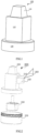


Classifications
-
- G—PHYSICS
- G01—MEASURING; TESTING
- G01C—MEASURING DISTANCES, LEVELS OR BEARINGS; SURVEYING; NAVIGATION; GYROSCOPIC INSTRUMENTS; PHOTOGRAMMETRY OR VIDEOGRAMMETRY
- G01C15/00—Surveying instruments or accessories not provided for in groups G01C1/00 - G01C13/00
- G01C15/002—Active optical surveying means
-
- G—PHYSICS
- G01—MEASURING; TESTING
- G01B—MEASURING LENGTH, THICKNESS OR SIMILAR LINEAR DIMENSIONS; MEASURING ANGLES; MEASURING AREAS; MEASURING IRREGULARITIES OF SURFACES OR CONTOURS
- G01B11/00—Measuring arrangements characterised by the use of optical techniques
- G01B11/26—Measuring arrangements characterised by the use of optical techniques for measuring angles or tapers; for testing the alignment of axes
-
- G—PHYSICS
- G01—MEASURING; TESTING
- G01C—MEASURING DISTANCES, LEVELS OR BEARINGS; SURVEYING; NAVIGATION; GYROSCOPIC INSTRUMENTS; PHOTOGRAMMETRY OR VIDEOGRAMMETRY
- G01C1/00—Measuring angles
-
- G—PHYSICS
- G01—MEASURING; TESTING
- G01C—MEASURING DISTANCES, LEVELS OR BEARINGS; SURVEYING; NAVIGATION; GYROSCOPIC INSTRUMENTS; PHOTOGRAMMETRY OR VIDEOGRAMMETRY
- G01C15/00—Surveying instruments or accessories not provided for in groups G01C1/00 - G01C13/00
-
- G—PHYSICS
- G01—MEASURING; TESTING
- G01C—MEASURING DISTANCES, LEVELS OR BEARINGS; SURVEYING; NAVIGATION; GYROSCOPIC INSTRUMENTS; PHOTOGRAMMETRY OR VIDEOGRAMMETRY
- G01C15/00—Surveying instruments or accessories not provided for in groups G01C1/00 - G01C13/00
- G01C15/02—Means for marking measuring points
- G01C15/06—Surveyors' staffs; Movable markers
-
- G—PHYSICS
- G01—MEASURING; TESTING
- G01C—MEASURING DISTANCES, LEVELS OR BEARINGS; SURVEYING; NAVIGATION; GYROSCOPIC INSTRUMENTS; PHOTOGRAMMETRY OR VIDEOGRAMMETRY
- G01C3/00—Measuring distances in line of sight; Optical rangefinders
- G01C3/02—Details
- G01C3/06—Use of electric means to obtain final indication
- G01C3/08—Use of electric radiation detectors
-
- G—PHYSICS
- G01—MEASURING; TESTING
- G01S—RADIO DIRECTION-FINDING; RADIO NAVIGATION; DETERMINING DISTANCE OR VELOCITY BY USE OF RADIO WAVES; LOCATING OR PRESENCE-DETECTING BY USE OF THE REFLECTION OR RERADIATION OF RADIO WAVES; ANALOGOUS ARRANGEMENTS USING OTHER WAVES
- G01S11/00—Systems for determining distance or velocity not using reflection or reradiation
- G01S11/12—Systems for determining distance or velocity not using reflection or reradiation using electromagnetic waves other than radio waves
-
- G—PHYSICS
- G01—MEASURING; TESTING
- G01S—RADIO DIRECTION-FINDING; RADIO NAVIGATION; DETERMINING DISTANCE OR VELOCITY BY USE OF RADIO WAVES; LOCATING OR PRESENCE-DETECTING BY USE OF THE REFLECTION OR RERADIATION OF RADIO WAVES; ANALOGOUS ARRANGEMENTS USING OTHER WAVES
- G01S17/00—Systems using the reflection or reradiation of electromagnetic waves other than radio waves, e.g. lidar systems
- G01S17/02—Systems using the reflection of electromagnetic waves other than radio waves
- G01S17/06—Systems determining position data of a target
Definitions
- the present disclosure generally relates to the field of distance measurement and positioning and, more particularly, relates to a method for measuring an angle and a distance, a method for plotting a trajectory map, and a laser ranging system employing the methods thereof.
- EP 2 103 905 A2 discloses a surveying instrument for measuring a 3-dimensional position of a measured object. Furthermore, in the existing technology, a level projects a visible laser beam, and then an elevation can be accurately located according to the laser beam. The level may also be driven by a rapidly rotating shaft to sweep a visible laser beam (generally a red or green light beam) at a same elevation for an engineer to locate the same elevation.
- a visible laser beam generally a red or green light beam
- the commonly available level may be generally categorized into three types: a bubble leveling laser level, a self-leveling laser level, and an electronic automatic leveling laser level.
- the bubble leveling laser level has a simple structure and a low cost so that the bubble leveling laser level is a popular instrument suitable for construction work such as building construction and interior decoration.
- Laser light emitted from a laser diode contained in the bubble leveling laser level passes through an objective lens to obtain a laser beam.
- the laser beam is split into two beams after passing through a pentagonal prism. One of the two beams passes directly and the other beam changes its direction by about 90 degrees.
- a rotating head of the instrument is driven by an electric motor through a belt to rotate and form a scanning laser plane.
- a long bubble level is configured on the instrument for leveling the instrument. Similar to the bubble level, the instrument uses the bubble level as a reference.
- the accuracy of the leveling of the laser plane depends on the precision of the bubble level.
- a laser scanned vertical plane is obtained based on a vertical bubble level.
- the accuracy of the instrument is substantially affected by human factors. Because construction and engineering operations require convenience and swiftness and certain special applications require high accuracy, the bubble level is unable to satisfy these requirements.
- a variety of automatic leveling laser instruments and unique leveling methods become available to satisfy these requirements.
- the automatic leveling laser level is an instrument using a wire suspended optical compensator to achieve the objective of automatic leveling within a certain range. No matter how the instrument is tilted, the scanned laser plane always maintains leveled or horizontal within a compensation range.
- the instrument is suitable for construction sites having substantial vibrations.
- the electronic automatic leveling laser level includes an opto-mechanical compensator and has the advantages of a simple structure, a low cost, and insensitivity to vibrations.
- the compensation accuracy decreases as the compensation range increases.
- the compensation accuracy is limited to about 1/10 th inch at 100 feet.
- Recently developed electronic automatic leveling mechanisms expand the compensation range while maintaining substantially high stability and compensation accuracy.
- the rotating head of the instrument facilitates sweeping the laser beam to form the scanned laser plane, thereby instructing the operator to perform corresponding construction operation.
- the instruments may be implemented sufficiently with the rotating head without the need for rotating the instruments themselves.
- the instruments require a solid base to stably fix the levels to a reference surface.
- the levels are required to be fixed to the reference surface, the levels are unable to rotate to follow movement of a detector. Thus, the levels are unable to measure different distances at different angles and unable to plot a trajectory map of a traveling route of the detector.
- one aspect of the present disclosure provides a method for measuring an angle and a distance as defined in claim 1.
- the method for measuring the angle and the distance creatively records the corresponding angle and distance at different positions, respectively, such that the position of the laser receiving device relative to the laser emitting device is accurately determined.
- the method further includes: rotating the laser receiving device around the laser emitting device for at least one round.
- the laser emitting device is able to measure or calculate a distance at a corresponding direction to determine a trajectory of the laser receiving device.
- the first angle and the second angle are recorded as a difference between a current direction and a true north direction.
- the trajectory of the laser receiving device is associated with the directions, thereby preparing for subsequent matching of the trajectory of the laser receiving device to a corresponding map.
- the true north direction is indicated by means of an orientation sensor.
- the orientation sensor includes, but is not limited to, a gyroscope, an electronic compass, and a code wheel.
- the method further includes: recording and saving the first angle and the first distance as one pair; and recording and saving the second angle and the second distance as another pair. As such, the corresponding angle and distance are saved in one pair, thereby providing convenience for subsequent plotting.
- measuring the first distance between the laser emitting device and the laser receiving device further includes: using a first laser emitting component of the laser emitting device to emit a vertical laser beam rotating in a vertical plane at a first rotation speed; using a first optical detection component and a second optical component that are at least partially located on a same vertical plane to calculate a time difference when the vertical laser beam reaches the first optical detection component and the second optical detection component, where a distance between the two optical components is called a first separation distance; and according to the first rotation speed, the first separation distance, and the time difference, calculating the first distance.
- the laser receiving device is vertically set by a universal joint or a horizontally-set bearing.
- the laser receiving device is vertically set by an angle sensor and a control motor.
- Another aspect of the present disclosure provides a method for plotting a trajectory map as defined in claim 8.
- the method further includes: rotating the laser receiving device around the laser emitting device for at least one round.
- the first angle and the second angle are recorded as a difference between a current direction and a true north direction.
- the true north direction is indicated by means of an orientation sensor.
- the orientation sensor includes, but is not limited to, a gyroscope, an electronic compass, and a code wheel.
- measuring the first distance between the laser emitting device and the laser receiving device further includes: using a first laser emitting component of the laser emitting device to emit a vertical laser beam rotating in a vertical plane at a first rotation speed; using a first optical detection component and a second optical component that are at least partially located on a same vertical plane to calculate a time difference when the vertical laser beam reaches the first optical detection component and the second optical detection component, where a distance between the two optical components is called a first separation distance; and according to the first rotation speed, the first separation distance, and the time difference, calculating the first distance.
- the laser ranging system is configured implement the disclosed method for measuring the angle and the distance or the disclosed method for plotting the trajectory map.
- the method for measuring the angle and the distance creatively records the corresponding angle and distance at different positions, respectively, such that the position of the laser receiving device relative to the laser emitting device is accurately determined.
- horizontal setting and vertical setting both refer to the arrangement of photosensitive elements included in an optical detection component of a laser receiving device.
- vertical setting means that the photosensitive elements such as stripes included in the optical detection component of the laser receiving device are arranged substantially perpendicular to a horizontal plane while the term “horizontal setting” means that the photosensitive elements such as stripes included in the optical detection component of the laser receiving device are arranged substantially on a same horizontal plane.
- FIG. 1 illustrates a schematic diagram of an example of a laser emitting device according to the existing technology.
- the laser emitting device 100 according to the existing technology such as a level, includes a base 130, a housing 110 fixed to the base 130, and a rotating head 120 mounted on the upper part of the housing 110.
- the rotating head 120 is able to sweep a plane and to show the plane to a construction worker to instruct the construction worker to perform subsequent operations.
- the rotating head 120 because the rotating head 120 is able to rotate to form a laser scanned leveling plane through a laser beam, it is only necessary to fix the housing 110 relative to the base 130.
- the housing 110 may be securely fixed to the base 130, such that the laser emitting device 100 is able to stably sweep the laser plane.
- the laser emitting device includes: a housing, a first laser emitting component configured to be rotatably mounted on the housing, a base coupled to the housing, and a driving mechanism configured to rotate the housing at a pre-determined angle in a first plane. Equipped with the driving mechanism, the laser emitting device according to the present disclosure includes the housing capable of rotating relative to the base, thereby achieving adjusting the direction of the laser beam in a vertical plane.
- the laser emitting device according to the present disclosure overcomes the technical bias that the base is configured not to rotate relative to the housing in the existing technology and creatively introduces the driving mechanism to drive the base to rotate relative to the housing to adjust the direction of the laser beam in the vertical plane.
- the first laser emitting component is configured to emit an automatically leveled laser beam in a vertical direction.
- the laser emitting device is able to emit the automatically leveled laser beam in the vertical direction, that is, the laser beam perpendicular to the horizontal plane, thereby facilitating subsequent marking.
- the laser emitting device further includes a second laser emitting component configured to be rotatably mounted on the housing. As such, the laser emitting device is able to not only emit the laser beam in the vertical direction, but also emit another laser beam not in the vertical direction.
- the second laser emitting component is configured to emit automatically leveled laser beam in a horizontal direction.
- the laser emitting device is able to emit automatically leveled laser beam in the horizontal direction, thereby facilitating the subsequent marking.
- the laser beam emitted from the first laser emitting component forms the first plane and the laser beam emitted from the second laser emitting component forms a second plane.
- the first plane and the second plane are perpendicular to each other.
- the laser emitting device is able to emit the automatically leveled laser beam in the vertical direction and the automatically leveled laser beam in the horizontal direction perpendicular to the vertical direction, thereby facilitating the subsequent marking.
- the driving mechanism includes an electric motor.
- the electric motor is a stepper motor. As such, an amount of rotation by the stepper motor can be controlled, thereby providing the possibility for subsequent positioning by means of the laser emitting device.
- the base is marked with an angle scale. As such, it is possible to visually monitor an angle of the rotation of the housing driven by the driving mechanism.
- the laser emitting device further includes a control circuit configured to control the amount of the rotation by the driving mechanism.
- the control circuit is able to rapidly control the amount of the rotation by the driving mechanism.
- the control circuit of the laser emitting device is coupled with the laser receiving device for detecting the laser beam emitted from the laser emitting device.
- the control circuit is able to communicatively couple with the laser receiving device for detecting the laser beam emitted from the laser emitting device.
- the amount of the rotation by the driving mechanism can be controlled through the feedback from the laser receiving device for detecting the laser beam emitted from the laser emitting device.
- the control circuit is configured to control the amount of the rotation by the driving mechanism through the feedback signal from the laser receiving device.
- the control circuit is able to communicatively couple with the laser receiving device for detecting the laser beam emitted from the laser emitting device.
- the amount of the rotation by the driving mechanism can be controlled through the feedback signal from the laser receiving device for detecting the laser beam emitted from the laser emitting device.
- the housing of the laser emitting device may rotate relative to the base, thereby achieving adjusting the direction of the laser beam in the vertical plane.
- the laser emitting device according to the present disclosure overcomes the technical bias that the base is configured not to rotate relative to the housing in the existing technology and creatively introduces the driving mechanism to drive the base to rotate relative to the housing to adjust the direction of the laser beam in the vertical plane.
- a laser emitting circuit is able to track the laser receiving circuit and to measure a relative position of the laser emitting circuit relative to the laser receiving circuit at a specific moment.
- the relative position includes both an angle and a distance.
- FIG. 2 illustrates a schematic diagram of an example of a laser emitting device used in a method according to some embodiments of the present disclosure.
- FIG. 3 illustrates a schematic diagram of another example of a laser emitting device used in a method according to some embodiments of the present disclosure.
- the laser emitting device 200 (e.g., the level 200) used in the tracking method according to the present disclosure includes a housing 200 and a first laser emitting component 240.
- the first laser emitting component 240 (e.g., a rotating head 240) is configured to be rotatably mounted on the housing 210, such that the first laser emitting component 240 is able to rotate in a plane to sweep a laser beam to form a leveling plane.
- the laser emitting device 200 further includes a base 230 coupled with the housing 210.
- the laser emitting device 200 further includes a driving mechanism 250.
- the driving mechanism 250 is configured to drive the housing 210 to rotate at a pre-determined angle in the first plane.
- the housing 210 of the laser emitting device 200 may rotate relative to the base 230, thereby achieving adjusting the direction of a rotating laser plane emitted from the first laser emitting component such as the rotating head 240.
- the laser emitting device 200 used in the tracking method according to the present disclosure overcomes the technical bias that the base 130 is configured not to rotate relative to the housing 110 in the existing technology and creatively introduces the driving mechanism 250 to drive the base 230 to rotate relative to the housing 210 to adjust the direction of the laser beam.
- the first laser emitting component 240 is configured to emit the automatically leveled laser beam in the vertical direction.
- the laser emitting device 200 further includes a second laser emitting component 220 configured to be rotatably mounted on the housing 210.
- the second laser emitting component 220 is further configured to emit the automatically leveled laser beam in the horizontal direction.
- the laser beam emitted from the first laser emitting component 240 forms the first plane
- the laser beam emitted from the second laser emitting component 220 forms the second plane.
- the first plane and the second plane are perpendicular with each other.
- the driving mechanism 250 includes an electric motor. More specifically, the electric motor is configured to be a stepper motor.
- the amount of the rotation by the stepper motor can be controlled, thereby providing the possibility for subsequent positioning by means of the laser emitting device.
- the rotated angle of the laser emitting device may also be directly obtained from the rotated angle of the electric motor, thereby obtaining angles corresponding to different positions to which the laser receiving device is moved.
- the base 230 is marked with an angle scale. As such, it is possible to visually monitor an angle of the rotation of the housing driven by the driving mechanism 250.
- the laser emitting device 200 also includes a control circuit (not shown in the drawing) configured to control the amount of the rotation by the driving mechanism 250.
- control circuit of the laser emitting device 200 is coupled with the laser receiving device (not shown in the drawing) for detecting the laser beam emitted from the laser emitting device 200.
- the control circuit is configured to control the amount of the rotation by the driving mechanism 250 through the feedback signal from the laser receiving device.
- the driving mechanism 250 is directly mounted inside the housing 210 and an output shaft of the driving mechanism 250 is directly or indirectly installed to the housing 210 to drive the housing 210 to rotate relative to the base 230.
- the laser emitting device 300 (e.g., the level 300) used in the tracking method according to the present disclosure includes a housing 310 and a first laser emitting component 340.
- the first laser emitting component 340 (e.g., a rotating head 340) is configured to be rotatably mounted on the housing 310, such that the first laser emitting component 340 is able to rotate in a plane to sweep a laser beam to form a leveling plane.
- the laser emitting device 300 further includes a base 330 coupled with the housing 310.
- the laser emitting device 300 further includes a driving mechanism. The driving mechanism is configured to drive the housing 310 to rotate at a pre-determined angle in the first plane.
- the housing 310 of the laser emitting device 300 may rotate relative to the base 330, thereby achieving adjusting the direction of a rotating laser plane emitted from the first laser emitting component 340 such as the rotating head 340.
- the laser emitting device 300 used in the tracking method according to the present disclosure overcomes the technical bias that the base 130 is configured not to rotate relative to the housing 110 in the existing technology and creatively introduces the driving mechanism to drive the base 330 to rotate relative to the housing 310 to adjust the direction of the laser beam.
- the first laser emitting component 340 is configured to emit the automatically leveled laser beam in the vertical direction.
- the laser emitting device 300 further includes a second laser emitting component 320 configured to be rotatably mounted on the housing 310.
- the second laser emitting component 320 is further configured to emit the automatically leveled laser beam in the horizontal direction.
- the laser beam emitted from the first laser emitting component 340 forms the first plane
- the laser beam emitted from the second laser emitting component 320 forms the second plane.
- the first plane and the second plane are perpendicular with each other.
- the driving mechanism includes an electric motor 351. More specifically, the electric motor is configured to be a stepper motor.
- the amount of the rotation by the stepper motor can be controlled, thereby providing the possibility for subsequent positioning by means of the laser emitting device.
- the base 330 is marked with an angle scale. As such, it is possible to visually monitor an angle of the rotation of the housing driven by the driving mechanism.
- the laser emitting device 300 also includes a control circuit (not shown in the drawing) configured to control the amount of the rotation by the driving mechanism. In this way, the control circuit of the laser emitting device 300 is coupled with the laser receiving device (not shown in the drawing) for detecting the laser beam emitted from the laser emitting device 300. The control circuit is configured to control the amount of the rotation by the driving mechanism through the feedback signal from the laser receiving device.
- the driving mechanism includes an electric motor 351, a drive shaft 352, a drive wheel 353, and a connecting shaft 354.
- the electric motor is installed inside the housing 310.
- the output shaft of the electric motor 351 directly or indirectly coupled with the drive shaft 352 drives the housing 310 to rotate relative to the base 330 through the drive wheel 353 and the connecting shaft 354.
- the tracking method for tracking the laser receiving device in the laser emitting device includes: establishing, by the laser emitting device, a communication connection with the laser receiving device; receiving, by the laser emitting device, an indication signal from the laser receiving device, indicating a movement direction of the laser receiving device; and based on the indication signal, controlling, by the laser emitting device, the rotation of the laser emitting device until the laser beam emitted from the laser emitting device is realigned with the laser receiving device.
- the tracking method for tracking the laser receiving device in the laser emitting device enables the laser emitting device to obtain the movement direction of the laser receiving device through the communication connection established between the laser emitting device and the laser receiving device (e.g., the laser receiver), such that the laser emitting device is able to control the movement direction of itself based on the movement direction of the laser receiving device, thereby achieving the tracking of the laser receiving device by the laser emitting device.
- controlling, by the laser emitting device, the rotation of the laser emitting device further includes: based on the indication signal, controlling, by the laser emitting device, the rotation of the stepper motor included in the laser emitting device.
- controlling, by the laser emitting device, the rotation of the stepper motor included in the laser emitting device based on the indication signal.
- using the stepper motor effectively controls the rotation of the laser emitting device.
- using the stepper motor to control the amount of the rotation has the advantages of accurate control and high precision.
- the tracking method further includes: recording initially aligned positions of the laser emitting device and the laser receiving device as a first angle. In one embodiment, the tracking method further includes: recording the realigned positions of the laser emitting device and the laser receiving device as a second angle. In one embodiment, the first angle and the second angle are determined according to the angle scale (e.g., the angle scale on the base 230 and 330 in FIG. 2 and FIG. 3 , respectively) included in the laser emitting device. In addition, the in one embodiment, the tracking method further includes: detecting, by the laser emitting device, a distance between the laser emitting device and the laser receiving device.
- the angle scale e.g., the angle scale on the base 230 and 330 in FIG. 2 and FIG. 3
- the laser emitting device is able to measure the distances between the laser emitting device and the laser receiving device when the laser emitting device aligns with the laser receiving device at different angles.
- the first angle and the second angle are determined according to the rotation angles of the stepper motor.
- the first angle is a true north direction, that is, at the beginning of the measurement, the laser receiver of the laser receiving device is located at the true north direction of the laser emitting device such as the level.
- the laser beam emitted from the laser emitting device aligns with the laser receiving device and measures the distance between the laser emitting device and the laser receiving device as about 5 meters.
- the laser receiving device moves toward the east (not necessarily at the true east direction).
- the laser receiving device sends a signal indicating the movement direction to the laser emitting device.
- the signal may be in an electrical form or in an optical form.
- the laser emitting device controls the stepper motor included in the laser emitting device to rotate according to the signal indicating the movement direction, for example, rotate in a clockwise direction in the case of a top view.
- the laser beam emitted from the laser emitting device realigns with the laser receiving device at the second angle (e.g., about 10 degrees northeast), the distance between the laser emitting device and the laser receiving device is measured as about 6 meters.
- the laser emitting device is able to measure the different distances at the different angles.
- the establishing the communication connection between the laser emitting device and the laser receiving device includes establishing a wireless communication connection and/or an optical signal communication connection between the laser emitting device and the laser receiving device. As such, through the electrical or the optical communication link, the communication connection between the laser emitting device and the laser receiving device is established, such that the movement direction of the laser receiving device is sent to the laser emitting device in the form of the electrical or optical signal to instruct the laser emitting device to rotate to track the laser receiving device.
- the laser receiving device is configured with a second laser receiving circuit for receiving the laser beam emitted from the second laser emitting component of the laser emitting device and a first laser receiving circuit configured to be substantially perpendicular to the second laser receiving circuit for receiving the laser beam emitted from the first laser emitting component of the laser emitting device.
- the second laser receiving circuit includes two parts separated by a certain distance and may include a first optical detection component and a second optical detection component, which are configured in parallel with each other.
- the second laser receiving circuit is used to align with the searched horizontal laser plane emitted from the second laser emitting component to ensure that the laser receiving device is always located on a same reference plane during the measurement of the different points and to ensure the accuracy of the data of the angles and the distances collected at the different positions. Then, through adjusting the laser emitting device, the laser beam emitted from the first laser emitting component in the vertical direction is received by the first optical detection component and the second optical detection component of the first laser receiving device. Thus, the realignment is achieved and the distance measurement is secured.
- the distance between the laser emitting device and the laser receiving device further includes: using the first laser emitting component of the laser emitting device to emit the vertical laser beam rotating in the vertical plane at a first rotation speed; using the first optical detection component and the second optical component that are at least partially located on the same vertical plane to calculate a time difference when the vertical laser beam reaches the first optical detection component and the second optical detection component, where a distance between the two optical components is called a first separation distance; and according to the first rotation speed, the first separation distance, and the time difference, calculating a first distance between the laser emitting device and the laser receiving device.
- the laser receiving device is vertically set by a universal joint or a horizontally-set bearing and/or the laser receiving device is vertically set by an angle sensor and a control motor.
- the tracking method for tracking the laser receiving device in the laser emitting device enables the laser emitting device to obtain the movement direction of the laser receiving device through the communication connection established between the laser emitting device and the laser receiving device (e.g., the laser receiver), such that the laser emitting device is able to control the movement direction of itself based on the movement direction of the laser receiving device, thereby achieving the tracking of the laser receiving device by the laser emitting device.
- the laser emitting device is able to track the laser receiving device, the following describes how to measure the pair of the angle and the distance and how to use the obtained angle and distance data to plot a trajectory map of the laser receiving device in conjunction with FIG. 5 and FIG. 6 .
- FIG. 5 illustrates a schematic diagram of an example of a method for measuring an angle and a distance and plotting a trajectory map according to some embodiments of the present disclosure.
- FIG. 6 illustrates a schematic diagram of another example of a method for measuring an angle and a distance and plotting a trajectory map according to some embodiments of the present disclosure.
- the method uses the laser emitting device (e.g., the laser emitting device 520 such as the laser level shown in the center of FIG. 5 ) to measure the angle and the distance.
- the method records the angle (e.g., ⁇ 1) and measures the distance 11 between the laser emitting device 520 and the laser receiving device 560 after the laser emitting device 520 aligns with the laser receiving device 560. Then, the laser receiving device 560 moves for a certain distance.
- the method records the angle (e.g., ⁇ 2) and measures the distance l2 between the laser emitting device 520 and the laser receiving device 560 after the laser emitting device 520 realigns with the laser receiving device 560.
- the laser receiving device 560 rotates around the laser emitting device 520 for at least one round.
- the one round of the rotation is not necessarily in a shape shown in FIG. 5 and may be in other shapes.
- the above-described scheme artificially determines at which point the relative angle and the distance are measured.
- the angle ⁇ 1 and the angle ⁇ 2 are recorded as a difference between the current direction and the true north direction.
- the trajectory (e.g., 550) of the laser receiving device 560 is associated with the directions, preparing for subsequent matching of the trajectory of the laser receiving device 560 to a corresponding map.
- the angle ⁇ 1 and the distance 11 are recorded and saved as one pair and the angle ⁇ 2 and the distance l2 are recorded and saved as another pair.
- the true north direction is indicated by an orientation sensor.
- the orientation sensor herein includes, but is not limited to, a gyroscope, an electronic compass, and a code wheel.
- the trajectory map of the laser receiving device 560 can be plotted based on the data pairs.
- the method for using the laser emitting device 520 to plot the trajectory map obtains the angles and the distances when the laser receiving device 560 is located at least at two different positions, thereby determining the trajectory of the laser receiving device 560.
- the method further includes: rotating the laser receiving device 560 around the laser emitting device 520 for at least one round.
- the method uses the laser emitting device 602 (e.g., the laser emitting device 620 such as the laser level shown in the center of FIG. 6 ) to measure the angle and the distance.
- the method records the angle (e.g., ⁇ 3) and measures the distance l3 between the laser emitting device 620 and the laser receiving device 660 after the laser emitting device 620 aligns with the laser receiving device 660. Then, the laser receiving device 660 moves for a certain distance.
- the method records the angle (e.g., ⁇ 4) and measures the distance l4 between the laser emitting device 620 and the laser receiving device 660 after the laser emitting device 620 realigns with the laser receiving device 660.
- the laser receiving device 660 is located at one side of the laser emitting device 620 and does not rotate around the laser emitting device 620 for at least one round.
- the above-described scheme artificially determines at which point the relative angle and the distance are measured.
- the angle ⁇ 3 and the angle ⁇ 4 are recorded as a difference between the current direction and the true north direction.
- the trajectory (e.g., 650) of the laser receiving device 660 is associated with the direction, preparing for subsequent matching the trajectory of the laser receiving device 660 to the corresponding map.
- the angle ⁇ 3 and the distance l3 are recorded and saved as one pair and the angle ⁇ 4 and the distance l4 are recorded and saved as another pair.
- the trajectory map 650 of the laser receiving device 660 can be plotted based on the data pairs.
- the method for using the laser emitting device 620 to plot the trajectory map obtains the angles and the distances when the laser receiving device 660 is located at least at two different positions, thereby determining the trajectory of the laser receiving device 660.
- the present disclosure also provides a laser ranging system configured to implement the method for measuring the angel and the distance or the method for plotting the trajectory map.
- the detector of the laser receiving device needs to include a timing circuit.
- the timing circuit is configured to initialize the first angle as 0 degree at the initial position and to record the current position as the initial position. At the initial position, the timing circuit is reset to zero.
- the timing circuit knows N counts (e.g., 100) corresponding to the one round of the rotation of the laser emitting device. Then, the laser receiving device moves to a first position different from the initial position.
- the timing circuit starts counting at the initial position and counts to M (M is cycled between 0 and 100, e.g., 10) at this time. Then, the difference between the first angle and the second angle is (M/N)*360 degrees. In one embodiment, the difference is (10/100)*360 degrees, that is, 36 degrees.
- the N counts may be pre-configured.
- a value is pre-configured at the time the timing circuit starts to operate.
- the value corresponds to one of many cooperation modes between the laser emitting device and the laser receiving device.
- the value is pre-configured to be 80, that is, the timing circuit counts to 80 after the laser beam emitted from the laser emitting device rotates for one round.
- the laser receiving device detects the N counts by itself. For example, at the beginning, the laser receiving device remains at the initial position for a certain time to detect a cycle that the laser receiving device receives the laser beam emitted from the laser emitting device. For example, for every 100 counts, the laser receiving device receives the laser beam emitted from the laser emitting device once. That is, the timing circuit counts to 100 after the laser beam emitted from the laser emitting device rotates for one round.
Landscapes
- Physics & Mathematics (AREA)
- Engineering & Computer Science (AREA)
- General Physics & Mathematics (AREA)
- Radar, Positioning & Navigation (AREA)
- Remote Sensing (AREA)
- Electromagnetism (AREA)
- Computer Networks & Wireless Communication (AREA)
- Optical Radar Systems And Details Thereof (AREA)
Description
- The present disclosure generally relates to the field of distance measurement and positioning and, more particularly, relates to a method for measuring an angle and a distance, a method for plotting a trajectory map, and a laser ranging system employing the methods thereof.
-
EP 2 103 905 A2 discloses a surveying instrument for measuring a 3-dimensional position of a measured object. Furthermore, in the existing technology, a level projects a visible laser beam, and then an elevation can be accurately located according to the laser beam. The level may also be driven by a rapidly rotating shaft to sweep a visible laser beam (generally a red or green light beam) at a same elevation for an engineer to locate the same elevation. - At present, based on the operation principle of the laser level, the presence or absence of an additional compensation mechanism, and the type of the compensation mechanism, the commonly available level may be generally categorized into three types: a bubble leveling laser level, a self-leveling laser level, and an electronic automatic leveling laser level.
- The bubble leveling laser level has a simple structure and a low cost so that the bubble leveling laser level is a popular instrument suitable for construction work such as building construction and interior decoration. Laser light emitted from a laser diode contained in the bubble leveling laser level passes through an objective lens to obtain a laser beam. The laser beam is split into two beams after passing through a pentagonal prism. One of the two beams passes directly and the other beam changes its direction by about 90 degrees. A rotating head of the instrument is driven by an electric motor through a belt to rotate and form a scanning laser plane. A long bubble level is configured on the instrument for leveling the instrument. Similar to the bubble level, the instrument uses the bubble level as a reference. In other words, the accuracy of the leveling of the laser plane depends on the precision of the bubble level. When the instrument is placed horizontally, a laser scanned vertical plane is obtained based on a vertical bubble level. The accuracy of the instrument is substantially affected by human factors. Because construction and engineering operations require convenience and swiftness and certain special applications require high accuracy, the bubble level is unable to satisfy these requirements. Thus, a variety of automatic leveling laser instruments and unique leveling methods become available to satisfy these requirements.
- The automatic leveling laser level is an instrument using a wire suspended optical compensator to achieve the objective of automatic leveling within a certain range. No matter how the instrument is tilted, the scanned laser plane always maintains leveled or horizontal within a compensation range. The instrument is suitable for construction sites having substantial vibrations.
- The electronic automatic leveling laser level includes an opto-mechanical compensator and has the advantages of a simple structure, a low cost, and insensitivity to vibrations. However, the compensation accuracy decreases as the compensation range increases. Generally, the compensation accuracy is limited to about 1/10th inch at 100 feet. Recently developed electronic automatic leveling mechanisms expand the compensation range while maintaining substantially high stability and compensation accuracy.
- In all three types of laser levels described above, the rotating head of the instrument facilitates sweeping the laser beam to form the scanned laser plane, thereby instructing the operator to perform corresponding construction operation. In these types of the levels, because the laser beam only sweeps on the leveled plane, the instruments may be implemented sufficiently with the rotating head without the need for rotating the instruments themselves. Correspondingly, the instruments require a solid base to stably fix the levels to a reference surface.
- Because the levels are required to be fixed to the reference surface, the levels are unable to rotate to follow movement of a detector. Thus, the levels are unable to measure different distances at different angles and unable to plot a trajectory map of a traveling route of the detector.
- In response to the above technical problems, that is, the level in the existing technology is unable to measure different distances at different angles or to plot a trajectory map of a laser receiving device, one aspect of the present disclosure provides a method for measuring an angle and a distance as defined in claim 1.
- The method for measuring the angle and the distance creatively records the corresponding angle and distance at different positions, respectively, such that the position of the laser receiving device relative to the laser emitting device is accurately determined.
- In one embodiment consistent with the present disclosure, the method further includes: rotating the laser receiving device around the laser emitting device for at least one round. As such, after the laser receiving device rotates around the laser emitting device for at least one round, the laser emitting device is able to measure or calculate a distance at a corresponding direction to determine a trajectory of the laser receiving device.
- In one embodiment consistent with the present disclosure, the first angle and the second angle are recorded as a difference between a current direction and a true north direction. As such, the trajectory of the laser receiving device is associated with the directions, thereby preparing for subsequent matching of the trajectory of the laser receiving device to a corresponding map.
- In one embodiment consistent with the present disclosure, the true north direction is indicated by means of an orientation sensor. Those skilled in the art should understand that the orientation sensor includes, but is not limited to, a gyroscope, an electronic compass, and a code wheel.
- In one embodiment consistent with the present disclosure, the method further includes: recording and saving the first angle and the first distance as one pair; and recording and saving the second angle and the second distance as another pair. As such, the corresponding angle and distance are saved in one pair, thereby providing convenience for subsequent plotting.
- In one embodiment consistent with the present disclosure, measuring the first distance between the laser emitting device and the laser receiving device further includes: using a first laser emitting component of the laser emitting device to emit a vertical laser beam rotating in a vertical plane at a first rotation speed; using a first optical detection component and a second optical component that are at least partially located on a same vertical plane to calculate a time difference when the vertical laser beam reaches the first optical detection component and the second optical detection component, where a distance between the two optical components is called a first separation distance; and according to the first rotation speed, the first separation distance, and the time difference, calculating the first distance.
- In one embodiment consistent with the present disclosure, the laser receiving device is vertically set by a universal joint or a horizontally-set bearing.
- In one embodiment consistent with the present disclosure, the laser receiving device is vertically set by an angle sensor and a control motor.
- Another aspect of the present disclosure provides a method for plotting a trajectory map as defined in claim 8.
- In one embodiment consistent with the present disclosure, the method further includes: rotating the laser receiving device around the laser emitting device for at least one round.
- In one embodiment consistent with the present disclosure, the first angle and the second angle are recorded as a difference between a current direction and a true north direction.
- In one embodiment consistent with the present disclosure, the true north direction is indicated by means of an orientation sensor. Those skilled in the art should understand that the orientation sensor includes, but is not limited to, a gyroscope, an electronic compass, and a code wheel.
- In one embodiment consistent with the present disclosure, measuring the first distance between the laser emitting device and the laser receiving device further includes: using a first laser emitting component of the laser emitting device to emit a vertical laser beam rotating in a vertical plane at a first rotation speed; using a first optical detection component and a second optical component that are at least partially located on a same vertical plane to calculate a time difference when the vertical laser beam reaches the first optical detection component and the second optical detection component, where a distance between the two optical components is called a first separation distance; and according to the first rotation speed, the first separation distance, and the time difference, calculating the first distance.
- Further, another aspect of the present disclosure provides a laser ranging system. The laser ranging system is configured implement the disclosed method for measuring the angle and the distance or the disclosed method for plotting the trajectory map.
- As such, the method for measuring the angle and the distance creatively records the corresponding angle and distance at different positions, respectively, such that the position of the laser receiving device relative to the laser emitting device is accurately determined.
- Embodiments are shown and described with reference to the accompanying drawings. The drawings clarify basic principles, thereby showing only the aspects necessary for understanding the basic principles. The drawings are not drawn to scale. In the drawings, same reference numerals denote similar features.
-
FIG. 1 illustrates a schematic diagram of an example of alaser emitting device 100 according to the existing technology; -
FIG. 2 illustrates a schematic diagram of an example of alaser emitting device 200 used in a method according to some embodiments of the present disclosure; -
FIG. 3 illustrates a schematic diagram of another example of alaser emitting device 300 used in a method according to some embodiments of the present disclosure; -
FIG. 4 illustrates a schematic diagram of an example of atracking method 400 for tracking a laser receiving device by a laser emitting device according to some embodiments of the present disclosure; -
FIG. 5 illustrates a schematic diagram 500 of an example of a method for measuring an angle and a distance and plotting a trajectory map according to some embodiments of the present disclosure; and -
FIG. 6 illustrates a schematic diagram 600 of another example of a method for measuring an angle and a distance and plotting a trajectory map according to some embodiments of the present disclosure. - Other features, characteristics, advantages and benefits of the present disclosure will become more apparent from the detailed description below in conjunction with the accompanying drawings.
- To make the foregoing objectives, features and advantages of the present disclosure clearer and more understandable, the present disclosure will be further described with reference to the accompanying drawings and embodiments. The attached drawings are for reference only and are not intended to limit the present disclosure.
- In the following detailed description of the preferred embodiments, reference will be made to the accompanying drawings, forming a part thereof. The accompanying drawings show specific embodiments as examples for implementing the present disclosure. The exemplary embodiments are not intended to be exhaustive of all embodiments according to the present disclosure. It can be understood that other embodiments may be used, and structural or logical modifications may be made without departing from the scope of the present disclosure. Thus, the detailed description below is not restrictive, and the scope of the present disclosure is defined by the appended claims.
- The applicant of this application wishes to make clear that the terms "horizontal setting" and "vertical setting" mentioned in the context of this application both refer to the arrangement of photosensitive elements included in an optical detection component of a laser receiving device. The term "vertical setting" means that the photosensitive elements such as stripes included in the optical detection component of the laser receiving device are arranged substantially perpendicular to a horizontal plane while the term "horizontal setting" means that the photosensitive elements such as stripes included in the optical detection component of the laser receiving device are arranged substantially on a same horizontal plane.
-
FIG. 1 illustrates a schematic diagram of an example of a laser emitting device according to the existing technology. As shown inFIG. 1 , thelaser emitting device 100 according to the existing technology, such as a level, includes abase 130, ahousing 110 fixed to thebase 130, and arotating head 120 mounted on the upper part of thehousing 110. Therotating head 120 is able to sweep a plane and to show the plane to a construction worker to instruct the construction worker to perform subsequent operations. In the existing technology, because therotating head 120 is able to rotate to form a laser scanned leveling plane through a laser beam, it is only necessary to fix thehousing 110 relative to thebase 130. In addition, because therotating head 120 rotates during the operation, to make therotating head 120 sufficiently stable when rotating, thehousing 110 may be securely fixed to thebase 130, such that thelaser emitting device 100 is able to stably sweep the laser plane. - To overcome the above technical bias, that is, the
housing 110 has to be securely fixed to the base 130 in the existing technology, the laser emitting device according to the present disclosure includes: a housing, a first laser emitting component configured to be rotatably mounted on the housing, a base coupled to the housing, and a driving mechanism configured to rotate the housing at a pre-determined angle in a first plane. Equipped with the driving mechanism, the laser emitting device according to the present disclosure includes the housing capable of rotating relative to the base, thereby achieving adjusting the direction of the laser beam in a vertical plane. The laser emitting device according to the present disclosure overcomes the technical bias that the base is configured not to rotate relative to the housing in the existing technology and creatively introduces the driving mechanism to drive the base to rotate relative to the housing to adjust the direction of the laser beam in the vertical plane. - The first laser emitting component is configured to emit an automatically leveled laser beam in a vertical direction. As such, the laser emitting device is able to emit the automatically leveled laser beam in the vertical direction, that is, the laser beam perpendicular to the horizontal plane, thereby facilitating subsequent marking.
- The laser emitting device further includes a second laser emitting component configured to be rotatably mounted on the housing. As such, the laser emitting device is able to not only emit the laser beam in the vertical direction, but also emit another laser beam not in the vertical direction.
- The second laser emitting component is configured to emit automatically leveled laser beam in a horizontal direction. As such, the laser emitting device is able to emit automatically leveled laser beam in the horizontal direction, thereby facilitating the subsequent marking.
- The laser beam emitted from the first laser emitting component forms the first plane and the laser beam emitted from the second laser emitting component forms a second plane. The first plane and the second plane are perpendicular to each other. As such, the laser emitting device is able to emit the automatically leveled laser beam in the vertical direction and the automatically leveled laser beam in the horizontal direction perpendicular to the vertical direction, thereby facilitating the subsequent marking.
- The driving mechanism includes an electric motor. In one embodiment, the electric motor is a stepper motor. As such, an amount of rotation by the stepper motor can be controlled, thereby providing the possibility for subsequent positioning by means of the laser emitting device.
- The base is marked with an angle scale. As such, it is possible to visually monitor an angle of the rotation of the housing driven by the driving mechanism.
- The laser emitting device further includes a control circuit configured to control the amount of the rotation by the driving mechanism. As such, the control circuit is able to rapidly control the amount of the rotation by the driving mechanism.
- The control circuit of the laser emitting device is coupled with the laser receiving device for detecting the laser beam emitted from the laser emitting device. As such, the control circuit is able to communicatively couple with the laser receiving device for detecting the laser beam emitted from the laser emitting device. Thus, the amount of the rotation by the driving mechanism can be controlled through the feedback from the laser receiving device for detecting the laser beam emitted from the laser emitting device.
- The control circuit is configured to control the amount of the rotation by the driving mechanism through the feedback signal from the laser receiving device. As such, the control circuit is able to communicatively couple with the laser receiving device for detecting the laser beam emitted from the laser emitting device. Thus, the amount of the rotation by the driving mechanism can be controlled through the feedback signal from the laser receiving device for detecting the laser beam emitted from the laser emitting device.
- Because the laser emitting device according to the present disclosure includes the driving mechanism, the housing of the laser emitting device may rotate relative to the base, thereby achieving adjusting the direction of the laser beam in the vertical plane. The laser emitting device according to the present disclosure overcomes the technical bias that the base is configured not to rotate relative to the housing in the existing technology and creatively introduces the driving mechanism to drive the base to rotate relative to the housing to adjust the direction of the laser beam in the vertical plane.
- In the case that the base rotates relative to the housing when driven by the driving mechanism, it is not yet possible to plot a motion trajectory of a detector of a laser receiving circuit. It is also required that a laser emitting circuit is able to track the laser receiving circuit and to measure a relative position of the laser emitting circuit relative to the laser receiving circuit at a specific moment. The relative position includes both an angle and a distance.
- The
laser emitting devices FIG. 2 andFIG. 3 .FIG. 2 illustrates a schematic diagram of an example of a laser emitting device used in a method according to some embodiments of the present disclosure.FIG. 3 illustrates a schematic diagram of another example of a laser emitting device used in a method according to some embodiments of the present disclosure. - As shown in
FIG. 2 , the laser emitting device 200 (e.g., the level 200) used in the tracking method according to the present disclosure includes ahousing 200 and a firstlaser emitting component 240. The first laser emitting component 240 (e.g., a rotating head 240) is configured to be rotatably mounted on thehousing 210, such that the firstlaser emitting component 240 is able to rotate in a plane to sweep a laser beam to form a leveling plane. In addition, thelaser emitting device 200 further includes a base 230 coupled with thehousing 210. Moreover, thelaser emitting device 200 further includes adriving mechanism 250. Thedriving mechanism 250 is configured to drive thehousing 210 to rotate at a pre-determined angle in the first plane. Because thelaser emitting device 200 used in the tracking method according to the present disclosure includes thedriving mechanism 250, thehousing 210 of thelaser emitting device 200 may rotate relative to thebase 230, thereby achieving adjusting the direction of a rotating laser plane emitted from the first laser emitting component such as therotating head 240. Thelaser emitting device 200 used in the tracking method according to the present disclosure overcomes the technical bias that thebase 130 is configured not to rotate relative to thehousing 110 in the existing technology and creatively introduces thedriving mechanism 250 to drive the base 230 to rotate relative to thehousing 210 to adjust the direction of the laser beam. The firstlaser emitting component 240 is configured to emit the automatically leveled laser beam in the vertical direction. - In addition, as shown in
FIG. 2 , thelaser emitting device 200 further includes a secondlaser emitting component 220 configured to be rotatably mounted on thehousing 210. The secondlaser emitting component 220 is further configured to emit the automatically leveled laser beam in the horizontal direction. In one embodiment, as shown inFIG. 2 , the laser beam emitted from the firstlaser emitting component 240 forms the first plane and the laser beam emitted from the secondlaser emitting component 220 forms the second plane. The first plane and the second plane are perpendicular with each other. In one embodiment, as shown inFIG. 2 , thedriving mechanism 250 includes an electric motor. More specifically, the electric motor is configured to be a stepper motor. As such, the amount of the rotation by the stepper motor can be controlled, thereby providing the possibility for subsequent positioning by means of the laser emitting device. In the tracking process, the rotated angle of the laser emitting device may also be directly obtained from the rotated angle of the electric motor, thereby obtaining angles corresponding to different positions to which the laser receiving device is moved. In one embodiment, as shown inFIG. 2 , thebase 230 is marked with an angle scale. As such, it is possible to visually monitor an angle of the rotation of the housing driven by thedriving mechanism 250. In addition, thelaser emitting device 200 also includes a control circuit (not shown in the drawing) configured to control the amount of the rotation by thedriving mechanism 250. In this way, the control circuit of thelaser emitting device 200 is coupled with the laser receiving device (not shown in the drawing) for detecting the laser beam emitted from thelaser emitting device 200. The control circuit is configured to control the amount of the rotation by thedriving mechanism 250 through the feedback signal from the laser receiving device. In one embodiment, as shown inFIG. 2 , thedriving mechanism 250 is directly mounted inside thehousing 210 and an output shaft of thedriving mechanism 250 is directly or indirectly installed to thehousing 210 to drive thehousing 210 to rotate relative to thebase 230. - As shown in
FIG. 3 , the laser emitting device 300 (e.g., the level 300) used in the tracking method according to the present disclosure includes ahousing 310 and a firstlaser emitting component 340. The first laser emitting component 340 (e.g., a rotating head 340) is configured to be rotatably mounted on thehousing 310, such that the firstlaser emitting component 340 is able to rotate in a plane to sweep a laser beam to form a leveling plane. In addition, thelaser emitting device 300 further includes a base 330 coupled with thehousing 310. Moreover, thelaser emitting device 300 further includes a driving mechanism. The driving mechanism is configured to drive thehousing 310 to rotate at a pre-determined angle in the first plane. Because thelaser emitting device 300 used in the tracking method according to the present disclosure includes the driving mechanism, thehousing 310 of thelaser emitting device 300 may rotate relative to thebase 330, thereby achieving adjusting the direction of a rotating laser plane emitted from the firstlaser emitting component 340 such as therotating head 340. Thelaser emitting device 300 used in the tracking method according to the present disclosure overcomes the technical bias that thebase 130 is configured not to rotate relative to thehousing 110 in the existing technology and creatively introduces the driving mechanism to drive the base 330 to rotate relative to thehousing 310 to adjust the direction of the laser beam. The firstlaser emitting component 340 is configured to emit the automatically leveled laser beam in the vertical direction. - In addition, as shown in
FIG. 3 , thelaser emitting device 300 further includes a secondlaser emitting component 320 configured to be rotatably mounted on thehousing 310. The secondlaser emitting component 320 is further configured to emit the automatically leveled laser beam in the horizontal direction. In one embodiment, as shown inFIG. 3 , the laser beam emitted from the firstlaser emitting component 340 forms the first plane and the laser beam emitted from the secondlaser emitting component 320 forms the second plane. The first plane and the second plane are perpendicular with each other. In one embodiment, as shown inFIG. 3 , the driving mechanism includes anelectric motor 351. More specifically, the electric motor is configured to be a stepper motor. As such, the amount of the rotation by the stepper motor can be controlled, thereby providing the possibility for subsequent positioning by means of the laser emitting device. In one embodiment, as shown inFIG. 3 , thebase 330 is marked with an angle scale. As such, it is possible to visually monitor an angle of the rotation of the housing driven by the driving mechanism. In addition, thelaser emitting device 300 also includes a control circuit (not shown in the drawing) configured to control the amount of the rotation by the driving mechanism. In this way, the control circuit of thelaser emitting device 300 is coupled with the laser receiving device (not shown in the drawing) for detecting the laser beam emitted from thelaser emitting device 300. The control circuit is configured to control the amount of the rotation by the driving mechanism through the feedback signal from the laser receiving device. In one embodiment, as shown inFIG. 2 , the driving mechanism includes anelectric motor 351, adrive shaft 352, adrive wheel 353, and a connectingshaft 354. The electric motor is installed inside thehousing 310. The output shaft of theelectric motor 351 directly or indirectly coupled with thedrive shaft 352 drives thehousing 310 to rotate relative to the base 330 through thedrive wheel 353 and the connectingshaft 354. - After the structure of the laser emitting device according to the present disclosure is described, the tracking method for tracking the laser receiving device in the laser emitting device is described below, the tracking method not falling under the claimed invention. The tracking method for tracking the laser receiving device in the laser emitting device includes: establishing, by the laser emitting device, a communication connection with the laser receiving device; receiving, by the laser emitting device, an indication signal from the laser receiving device, indicating a movement direction of the laser receiving device; and based on the indication signal, controlling, by the laser emitting device, the rotation of the laser emitting device until the laser beam emitted from the laser emitting device is realigned with the laser receiving device. Under the circumstance that the laser emitting device (e.g., the level) rotates, the tracking method for tracking the laser receiving device in the laser emitting device enables the laser emitting device to obtain the movement direction of the laser receiving device through the communication connection established between the laser emitting device and the laser receiving device (e.g., the laser receiver), such that the laser emitting device is able to control the movement direction of itself based on the movement direction of the laser receiving device, thereby achieving the tracking of the laser receiving device by the laser emitting device.
- Based on the indication signal, controlling, by the laser emitting device, the rotation of the laser emitting device further includes: based on the indication signal, controlling, by the laser emitting device, the rotation of the stepper motor included in the laser emitting device. As such, using the stepper motor effectively controls the rotation of the laser emitting device. In addition, using the stepper motor to control the amount of the rotation has the advantages of accurate control and high precision.
- The tracking method further includes: recording initially aligned positions of the laser emitting device and the laser receiving device as a first angle. In one embodiment, the tracking method further includes: recording the realigned positions of the laser emitting device and the laser receiving device as a second angle. In one embodiment, the first angle and the second angle are determined according to the angle scale (e.g., the angle scale on the
base FIG. 2 andFIG. 3 , respectively) included in the laser emitting device. In addition, the in one embodiment, the tracking method further includes: detecting, by the laser emitting device, a distance between the laser emitting device and the laser receiving device. As such, as the laser receiving device moves, the laser emitting device is able to measure the distances between the laser emitting device and the laser receiving device when the laser emitting device aligns with the laser receiving device at different angles. In one embodiment, the first angle and the second angle are determined according to the rotation angles of the stepper motor. - For example, the first angle is a true north direction, that is, at the beginning of the measurement, the laser receiver of the laser receiving device is located at the true north direction of the laser emitting device such as the level. At this time, the laser beam emitted from the laser emitting device aligns with the laser receiving device and measures the distance between the laser emitting device and the laser receiving device as about 5 meters. Then, the laser receiving device moves toward the east (not necessarily at the true east direction). The laser receiving device sends a signal indicating the movement direction to the laser emitting device. As previously described, the signal may be in an electrical form or in an optical form. After receiving the signal, the laser emitting device controls the stepper motor included in the laser emitting device to rotate according to the signal indicating the movement direction, for example, rotate in a clockwise direction in the case of a top view. As the laser beam emitted from the laser emitting device realigns with the laser receiving device at the second angle (e.g., about 10 degrees northeast), the distance between the laser emitting device and the laser receiving device is measured as about 6 meters. Thus, as the laser receiving device moves, the laser emitting device is able to measure the different distances at the different angles.
- The establishing the communication connection between the laser emitting device and the laser receiving device includes establishing a wireless communication connection and/or an optical signal communication connection between the laser emitting device and the laser receiving device. As such, through the electrical or the optical communication link, the communication connection between the laser emitting device and the laser receiving device is established, such that the movement direction of the laser receiving device is sent to the laser emitting device in the form of the electrical or optical signal to instruct the laser emitting device to rotate to track the laser receiving device.
- To achieve the alignment and the distance measurement, the laser receiving device according to the present disclosure is configured with a second laser receiving circuit for receiving the laser beam emitted from the second laser emitting component of the laser emitting device and a first laser receiving circuit configured to be substantially perpendicular to the second laser receiving circuit for receiving the laser beam emitted from the first laser emitting component of the laser emitting device. The second laser receiving circuit includes two parts separated by a certain distance and may include a first optical detection component and a second optical detection component, which are configured in parallel with each other. After the realignment is achieved, the second laser receiving circuit is used to align with the searched horizontal laser plane emitted from the second laser emitting component to ensure that the laser receiving device is always located on a same reference plane during the measurement of the different points and to ensure the accuracy of the data of the angles and the distances collected at the different positions. Then, through adjusting the laser emitting device, the laser beam emitted from the first laser emitting component in the vertical direction is received by the first optical detection component and the second optical detection component of the first laser receiving device. Thus, the realignment is achieved and the distance measurement is secured. Measuring, by the laser emitting device, the distance between the laser emitting device and the laser receiving device further includes: using the first laser emitting component of the laser emitting device to emit the vertical laser beam rotating in the vertical plane at a first rotation speed; using the first optical detection component and the second optical component that are at least partially located on the same vertical plane to calculate a time difference when the vertical laser beam reaches the first optical detection component and the second optical detection component, where a distance between the two optical components is called a first separation distance; and according to the first rotation speed, the first separation distance, and the time difference, calculating a first distance between the laser emitting device and the laser receiving device. The laser receiving device is vertically set by a universal joint or a horizontally-set bearing and/or the laser receiving device is vertically set by an angle sensor and a control motor.
- Under the circumstance that the laser emitting device (e.g., the level) rotates, the tracking method for tracking the laser receiving device in the laser emitting device enables the laser emitting device to obtain the movement direction of the laser receiving device through the communication connection established between the laser emitting device and the laser receiving device (e.g., the laser receiver), such that the laser emitting device is able to control the movement direction of itself based on the movement direction of the laser receiving device, thereby achieving the tracking of the laser receiving device by the laser emitting device.
- Under the circumstance that the laser emitting device is able to track the laser receiving device, the following describes how to measure the pair of the angle and the distance and how to use the obtained angle and distance data to plot a trajectory map of the laser receiving device in conjunction with
FIG. 5 and FIG. 6 . -
FIG. 5 illustrates a schematic diagram of an example of a method for measuring an angle and a distance and plotting a trajectory map according to some embodiments of the present disclosure.FIG. 6 illustrates a schematic diagram of another example of a method for measuring an angle and a distance and plotting a trajectory map according to some embodiments of the present disclosure. - As shown in
FIG. 5 , the method according to the present disclosure uses the laser emitting device (e.g., thelaser emitting device 520 such as the laser level shown in the center ofFIG. 5 ) to measure the angle and the distance. Specifically, at an initial position, that is, at the position where the laser receiving device 560 (e.g., the detector) is located, the method records the angle (e.g., Θ1) and measures the distance 11 between thelaser emitting device 520 and thelaser receiving device 560 after thelaser emitting device 520 aligns with thelaser receiving device 560. Then, thelaser receiving device 560 moves for a certain distance. The method records the angle (e.g., θ2) and measures the distance l2 between thelaser emitting device 520 and thelaser receiving device 560 after thelaser emitting device 520 realigns with thelaser receiving device 560. In one embodiment, as shown inFIG. 5 , thelaser receiving device 560 rotates around thelaser emitting device 520 for at least one round. Those skilled in the art should understand that the one round of the rotation is not necessarily in a shape shown inFIG. 5 and may be in other shapes. The above-described scheme artificially determines at which point the relative angle and the distance are measured. For example, the angle θ1 and the angle θ2 are recorded as a difference between the current direction and the true north direction. As such, the trajectory (e.g., 550) of thelaser receiving device 560 is associated with the directions, preparing for subsequent matching of the trajectory of thelaser receiving device 560 to a corresponding map. - In a specific operation, after the
laser emitting device 520 measures the angle and the distance at one position, the angle θ1 and the distance 11 are recorded and saved as one pair and the angle θ2 and the distance l2 are recorded and saved as another pair. The more such data pairs are collected and the shorter the collection time interval is, the more accurate thetrajectory 550 of the detector of thelaser receiving device 560 is. In one embodiment, the true north direction is indicated by an orientation sensor. Those skilled in the art should understand that the orientation sensor herein includes, but is not limited to, a gyroscope, an electronic compass, and a code wheel. - Next, after the data pairs such as (θ1, l1) and (θ2, l2) are obtained, the trajectory map of the
laser receiving device 560 can be plotted based on the data pairs. The method for using thelaser emitting device 520 to plot the trajectory map obtains the angles and the distances when thelaser receiving device 560 is located at least at two different positions, thereby determining the trajectory of thelaser receiving device 560. - In one embodiment, the method further includes: rotating the
laser receiving device 560 around thelaser emitting device 520 for at least one round. - As shown in
FIG. 6 , the method according to the present disclosure uses the laser emitting device 602 (e.g., the laser emitting device 620 such as the laser level shown in the center ofFIG. 6 ) to measure the angle and the distance. Specifically, at an initial position, that is, at the position where the laser receiving device 660 (e.g., the detector) is located, the method records the angle (e.g., θ3) and measures the distance l3 between the laser emitting device 620 and thelaser receiving device 660 after the laser emitting device 620 aligns with thelaser receiving device 660. Then, thelaser receiving device 660 moves for a certain distance. The method records the angle (e.g., θ4) and measures the distance l4 between the laser emitting device 620 and thelaser receiving device 660 after the laser emitting device 620 realigns with thelaser receiving device 660. In one embodiment, as shown inFIG. 6 , thelaser receiving device 660 is located at one side of the laser emitting device 620 and does not rotate around the laser emitting device 620 for at least one round. The above-described scheme artificially determines at which point the relative angle and the distance are measured. For example, the angle θ3 and the angle θ4 are recorded as a difference between the current direction and the true north direction. As such, the trajectory (e.g., 650) of thelaser receiving device 660 is associated with the direction, preparing for subsequent matching the trajectory of thelaser receiving device 660 to the corresponding map. - In a specific operation, after the laser emitting device 620 measures the angle and the distance at one position, the angle θ3 and the distance l3 are recorded and saved as one pair and the angle θ4 and the distance l4 are recorded and saved as another pair. The more such data pairs are collected and the shorter the collection time interval is, the more accurate the
trajectory 650 of the detector of thelaser receiving device 660 is. - Next, after the data pairs such as (θ3, l3) and (θ4, l4) are obtained, the
trajectory map 650 of thelaser receiving device 660 can be plotted based on the data pairs. The method for using the laser emitting device 620 to plot the trajectory map obtains the angles and the distances when thelaser receiving device 660 is located at least at two different positions, thereby determining the trajectory of thelaser receiving device 660. - Finally, the present disclosure also provides a laser ranging system configured to implement the method for measuring the angel and the distance or the method for plotting the trajectory map.
- Those skilled in the art should understand, that the laser emitting device incapable of tracking and the laser receiving device cooperate to implement the measurement of the angle and the distance and the plotting of the trajectory map. The detector of the laser receiving device needs to include a timing circuit. The timing circuit is configured to initialize the first angle as 0 degree at the initial position and to record the current position as the initial position. At the initial position, the timing circuit is reset to zero. In addition, the timing circuit knows N counts (e.g., 100) corresponding to the one round of the rotation of the laser emitting device. Then, the laser receiving device moves to a first position different from the initial position. Assuming that after being initialized at the initial position, the timing circuit starts counting at the initial position and counts to M (M is cycled between 0 and 100, e.g., 10) at this time. Then, the difference between the first angle and the second angle is (M/N)*360 degrees. In one embodiment, the difference is (10/100)*360 degrees, that is, 36 degrees.
- Here provides more description about how the timing circuit knows the N counts corresponding to one round of the rotation of the laser emitting device. There are many ways to achieve the same. Two embodiments are given below. However, the two embodiments are intended to be illustrative and not restrictive. Those skilled in the art should understand that any modifications made without departing from the inventive concept of the present disclosure fall within the protection scope of the appended claims.
- In one embodiment, the N counts may be pre-configured. For example, a value is pre-configured at the time the timing circuit starts to operate. The value corresponds to one of many cooperation modes between the laser emitting device and the laser receiving device. For example, the value is pre-configured to be 80, that is, the timing circuit counts to 80 after the laser beam emitted from the laser emitting device rotates for one round.
- In another embodiment, the laser receiving device detects the N counts by itself. For example, at the beginning, the laser receiving device remains at the initial position for a certain time to detect a cycle that the laser receiving device receives the laser beam emitted from the laser emitting device. For example, for every 100 counts, the laser receiving device receives the laser beam emitted from the laser emitting device once. That is, the timing circuit counts to 100 after the laser beam emitted from the laser emitting device rotates for one round.
- Those skilled in the art should understand that changes and modifications may be made to various embodiments disclosed above. Thus, the protection scope of the present disclosure should be defined by the appended claims.
Claims (11)
- A method for measuring an angle and a distance, comprising:at an initial position, after a laser emitting device (200, 300, 520, 620) aligns with a laser receiving device (560, 660), recording a first angle and measuring a first distance between the laser emitting device (200, 300, 520, 620) and the laser receiving device (560, 660); andmoving the laser receiving device (560, 660) from the initial position to a first position, and after the laser emitting device (200, 300, 520, 620) realigns with the laser receiving device (560, 660), recording a second angle and measuring a second distance between the laser emitting device (200, 300, 520, 620) and the laser receiving device (560, 660),characterized in that:the laser receiving device (560, 660) includes a timing circuit configured to:- know N counts corresponding to the one round of the rotation of the laser emitting device;- initialize the first angle as 0 degree at the initial position and to record the current position as the initial position, wherein at the initial position the timing circuit is reset to zero, and- obtain a difference between the first angle and the second angle,wherein after the laser receiving device moves to the first position and after being initialized at the initial position the timing circuit starts counting at the initial position and counts to M, M being cycled between 0 and N, at this time, andthe difference between the first angle and the second angle is (M/N)*360 degrees.
- The method according to claim 1, further comprising:
rotating the laser receiving device (560, 660) around the laser emitting device (200, 300, 520, 620) for at least one round. - The method according to claim 1, wherein:
the first angle and the second angle are recorded as a difference between a current direction and a true north direction. - The method according to claim 1, further comprising:recording and saving the first angle and the first distance as one pair; andrecording and saving the second angle and the second distance as another pair.
- The method according to claim 3, wherein:
the laser receiving device (560, 660) is vertically set by a universal joint or a horizontally-set bearing. - The method according to claim 3, wherein:
the laser receiving device (560, 660) is vertically set by an angle sensor and a control motor. - The method according to claim 1, wherein measuring the first distance between the laser emitting device (200, 300, 520, 620) and the laser receiving device (560, 660) further includes:using a first laser emitting component (240, 340) of the laser emitting device (200, 300, 520, 620) to emit a vertical laser beam rotating in a vertical plane at a first rotation speed;using a first optical detection component and a second optical component that are at least partially located on a same vertical plane to calculate a time difference when the vertical laser beam reaches the first optical detection component and the second optical detection component, wherein a distance between the two optical components is called a first separation distance; andaccording to the first rotation speed, the first separation distance, and the time difference, calculating the first distance.
- A method for plotting a trajectory map comprising:at an initial position, after a laser emitting device (200, 300, 520, 620) aligns with a laser receiving device (560, 660), recording a first angle and measuring a first distance between the laser emitting device (200, 300, 520, 620) and the laser receiving device (560, 660), and recording and saving the first angle and the first distance as a first data pair;moving the laser receiving device (560, 660) from the initial position to at least one first position, and after the laser emitting device (200, 300, 520, 620) realigns with the laser receiving device (560, 660), recording at least one second angle and measuring at least one second distance between the laser emitting device (200, 300, 520, 620) and the laser receiving device (560, 660), and recording and saving the at least one second angle and the at least one second distance as at least one second data pair; andbased on the first data pair and the at least one second data pair, plotting the trajectory map of the laser receiving device (560, 660),characterized in that:the laser receiving device (560, 660) includes a timing circuit configured to:- know N counts corresponding to the one round of the rotation of the laser emitting device;- initialize the first angle as 0 degree at the initial position and to record the current position as the initial position, wherein at the initial position the timing circuit is reset to zero, and- Obtain a difference between the first angle and the second angle,wherein after the laser receiving device moves to the first position and after being initialized at the initial position the timing circuit starts counting at the initial position and counts to M, M being cycled between 0 and N, at this time,the difference between the first angle and the second angle is (M/N)*360 degrees.
- The method according to claim 8, further comprising:
rotating the laser receiving device (560, 660) around the laser emitting device (200, 300, 520, 620) for at least one round. - The method according to claim 8, wherein measuring the first distance between the laser emitting device (200, 300, 520, 620) and the laser receiving device (560, 660) further includes:using a first laser emitting component (240, 340) of the laser emitting device (200, 300, 520, 620) to emit a vertical laser beam rotating in a vertical plane at a first rotation speed;using a first optical detection component and a second optical component that are at least partially located on a same vertical plane to calculate a time difference when the vertical laser beam reaches the first optical detection component and the second optical detection component, wherein a distance between the two optical components is called a first separation distance; andaccording to the first rotation speed, the first separation distance, and the time difference, calculating the first distance.
- A laser ranging system, wherein:
the laser ranging system is configured to implement the method of any of claims 1-7 or the method of any of claims 8-10.
Applications Claiming Priority (2)
| Application Number | Priority Date | Filing Date | Title |
|---|---|---|---|
| CN201710662589.5A CN109387826B (en) | 2017-08-04 | 2017-08-04 | Methods for measuring angles and distances, methods for drawing trajectory maps, and laser ranging systems |
| PCT/CN2018/096946 WO2019024731A1 (en) | 2017-08-04 | 2018-07-25 | Angle and distance measuring method, trajectory diagram drawing method, and laser ranging system |
Publications (3)
| Publication Number | Publication Date |
|---|---|
| EP3663715A1 EP3663715A1 (en) | 2020-06-10 |
| EP3663715A4 EP3663715A4 (en) | 2021-08-04 |
| EP3663715B1 true EP3663715B1 (en) | 2024-10-30 |
Family
ID=65233525
Family Applications (1)
| Application Number | Title | Priority Date | Filing Date |
|---|---|---|---|
| EP18840199.6A Active EP3663715B1 (en) | 2017-08-04 | 2018-07-25 | Angle and distance measuring method, trajectory diagram drawing method, and laser ranging system |
Country Status (4)
| Country | Link |
|---|---|
| US (1) | US11150087B2 (en) |
| EP (1) | EP3663715B1 (en) |
| CN (1) | CN109387826B (en) |
| WO (1) | WO2019024731A1 (en) |
Families Citing this family (18)
| Publication number | Priority date | Publication date | Assignee | Title |
|---|---|---|---|---|
| CN107218920B (en) * | 2017-08-04 | 2020-07-10 | 美国西北仪器公司 | Distance measuring method and distance measuring system |
| CN109916309B (en) * | 2019-03-04 | 2024-04-26 | 中铁第四勘察设计院集团有限公司 | Ground surface crack monitoring device and method based on laser ranging |
| CN109974630B (en) * | 2019-04-26 | 2025-02-07 | 湖北刊江建设工程有限公司 | Angle detection device |
| US11577859B1 (en) * | 2019-10-08 | 2023-02-14 | Rockwell Collins, Inc. | Fault resilient airborne network |
| US11802948B2 (en) * | 2020-04-24 | 2023-10-31 | Crown Equipment Corporation | Industrial vehicle distance and range measurement device calibration |
| CN114061920B (en) * | 2020-08-07 | 2025-01-28 | 北京小米移动软件有限公司 | Folding track detection device, folding track detection method, and folding detection system |
| CN112179324B (en) * | 2020-10-08 | 2022-08-23 | 山西省交通建设工程质量检测中心(有限公司) | Bridge pier column verticality detection device |
| CN112129264B (en) * | 2020-10-20 | 2025-02-07 | 四川大学 | Laser ranging sensor measurement system and measurement method |
| CN112496863B (en) * | 2020-11-23 | 2022-10-28 | 中国航发沈阳黎明航空发动机有限责任公司 | Automatic measuring method for numerical control machining angle |
| CN112953644B (en) * | 2021-01-25 | 2022-08-02 | 华中科技大学鄂州工业技术研究院 | Wireless communication method, device, communication device and storage medium for underwater robot group |
| WO2022216594A1 (en) * | 2021-04-05 | 2022-10-13 | Milwaukee Electric Tool Corporation | Laser level system |
| EP4320406A4 (en) | 2021-04-05 | 2025-04-09 | Milwaukee Electric Tool Corporation | ROTATING LASER WITH MECHANICAL MASK |
| CN113581702B (en) * | 2021-07-06 | 2022-10-11 | 浙江世仓智能仓储设备有限公司 | Positioning method based on driving distance of four-way vehicle |
| CN114683234B (en) * | 2022-05-09 | 2023-07-18 | 中国石油大学(华东) | An automatic device for rapid measurement and line drawing of pipeline hot joints |
| CN116202425B (en) * | 2022-06-15 | 2023-09-12 | 武汉鑫岳光电科技有限公司 | Laser ranging device |
| CN116007595A (en) * | 2022-12-28 | 2023-04-25 | 湖南中联重科应急装备有限公司 | Method for determining deflection, storage medium, processor and aerial vehicle |
| CN116499422B (en) * | 2023-04-27 | 2025-12-26 | 阿维塔科技(重庆)有限公司 | An auxiliary testing device and testing method |
| CN116379971B (en) * | 2023-05-29 | 2023-08-11 | 华北理工大学 | Laser measuring device and measuring method for verticality of metal component |
Family Cites Families (19)
| Publication number | Priority date | Publication date | Assignee | Title |
|---|---|---|---|---|
| US5243397A (en) * | 1992-11-25 | 1993-09-07 | Elop-Electrooptics Industries Ltd. | Distance measuring system |
| BE1008234A5 (en) * | 1994-03-25 | 1996-02-20 | Sotec B V I O | Device and operating method for measuring using lasers in more than onedimension |
| JP4328653B2 (en) * | 2004-03-23 | 2009-09-09 | 株式会社トプコン | Laser measurement system |
| JP5124319B2 (en) * | 2008-03-21 | 2013-01-23 | 株式会社トプコン | Surveying instrument, surveying system, measuring object detection method, and measuring object detection program |
| JP5124321B2 (en) * | 2008-03-21 | 2013-01-23 | 株式会社トプコン | Measuring system |
| US9400170B2 (en) * | 2010-04-21 | 2016-07-26 | Faro Technologies, Inc. | Automatic measurement of dimensional data within an acceptance region by a laser tracker |
| US8724119B2 (en) * | 2010-04-21 | 2014-05-13 | Faro Technologies, Inc. | Method for using a handheld appliance to select, lock onto, and track a retroreflector with a laser tracker |
| US9686532B2 (en) * | 2011-04-15 | 2017-06-20 | Faro Technologies, Inc. | System and method of acquiring three-dimensional coordinates using multiple coordinate measurement devices |
| EP2620745A1 (en) * | 2012-01-30 | 2013-07-31 | Hexagon Technology Center GmbH | Measuring system with a measuring device and a scan module |
| EP2639548A1 (en) | 2012-03-15 | 2013-09-18 | Leica Geosystems AG | Laser Receiver capable to detect its own Movements |
| EP2687866A1 (en) * | 2012-07-19 | 2014-01-22 | Leica Geosystems AG | Laser tracker with calibration unit for self-calibration |
| EP2746806B1 (en) * | 2012-12-21 | 2016-10-19 | Leica Geosystems AG | Self-calibrating laser tracker and auto calibration technique |
| CN103235302B (en) * | 2013-02-28 | 2014-10-15 | 中国地质大学(武汉) | Device and method for distance and speed measurement based on laser scanning and dual detector |
| US9188430B2 (en) * | 2013-03-14 | 2015-11-17 | Faro Technologies, Inc. | Compensation of a structured light scanner that is tracked in six degrees-of-freedom |
| EP2781879B1 (en) | 2013-03-19 | 2015-09-30 | Leica Geosystems AG | Construction laser system comprising rotation laser and laser receiver, with functionality for automatic determination of the laser receiver direction |
| CN103345269B (en) * | 2013-06-30 | 2017-08-25 | 湖南农业大学 | A kind of laser beam emitting device and method for automatic tracking |
| EP2894491B1 (en) * | 2013-12-18 | 2020-05-27 | LG Electronics Inc. | Distance measuring device and method thereof |
| CN205317206U (en) * | 2015-12-10 | 2016-06-15 | 新余学院 | Multifunctional measuring engineering instrument |
| CN106802412B (en) * | 2017-01-23 | 2020-08-04 | 南京大学 | Short-distance mobile positioning system and method based on laser and wireless technology |
-
2017
- 2017-08-04 CN CN201710662589.5A patent/CN109387826B/en active Active
-
2018
- 2018-07-25 EP EP18840199.6A patent/EP3663715B1/en active Active
- 2018-07-25 US US16/636,536 patent/US11150087B2/en active Active
- 2018-07-25 WO PCT/CN2018/096946 patent/WO2019024731A1/en not_active Ceased
Also Published As
| Publication number | Publication date |
|---|---|
| EP3663715A4 (en) | 2021-08-04 |
| CN109387826A (en) | 2019-02-26 |
| CN109387826B (en) | 2024-03-19 |
| EP3663715A1 (en) | 2020-06-10 |
| WO2019024731A1 (en) | 2019-02-07 |
| US20210156679A1 (en) | 2021-05-27 |
| US11150087B2 (en) | 2021-10-19 |
Similar Documents
| Publication | Publication Date | Title |
|---|---|---|
| US11150087B2 (en) | Angle and distance measuring method, trajectory diagram drawing method, and laser ranging system | |
| US11486704B2 (en) | Intelligent positioning module | |
| US10823558B2 (en) | Surveying instrument | |
| CN108291809B (en) | Method for verifying and/or calibrating the vertical axis of a rotating laser | |
| US7196302B2 (en) | Laser measuring method and laser measuring system having fan-shaped tilted laser beams and three known points of photodetection system | |
| CN105865426B (en) | A kind of total powerstation of automatic centering and measurement | |
| EP2788715B1 (en) | Robotic leveling | |
| EP2056066A2 (en) | Surveying Instrument | |
| EP2708969B1 (en) | Construction machine control method and construction machine control system | |
| US11500096B2 (en) | Surveying instrument | |
| EP1983299B1 (en) | Apparatus and method for determining an elevation of working tools based on a laser system | |
| KR101791955B1 (en) | Level that minimizes the error occurrence range of the survey information Geodetic survey apparatus | |
| JPS5912966B2 (en) | Method and device for automatically leveling a goniometer | |
| US20190154501A1 (en) | Procedure for Comparing a Reception Beam Impinging on a Laser Receiver with a Rotating Laser Beam | |
| US20140304995A1 (en) | Surveying System | |
| JP2019219319A (en) | Vertical measurement system and reference point tracing method | |
| CN205655835U (en) | Automatic centering and measuring total powerstation | |
| US12571631B2 (en) | Surveying instrument | |
| CN111271052A (en) | Combined device and method for measuring pile depth, pile diameter and pile hole perpendicularity | |
| EP0803044A1 (en) | Remotely operated levelling device | |
| CN109387827B (en) | Tracking method for tracking laser receiving device in laser transmitting device | |
| WO1996030720A1 (en) | Method and apparatus for measuring position and posture of tunnel excavator | |
| JP2024043881A (en) | Surveying instrument, operation method and program for surveying instrument | |
| GB2217454A (en) | Position measurement system | |
| CN107270880A (en) | A laser emitting device |
Legal Events
| Date | Code | Title | Description |
|---|---|---|---|
| STAA | Information on the status of an ep patent application or granted ep patent |
Free format text: STATUS: THE INTERNATIONAL PUBLICATION HAS BEEN MADE |
|
| PUAI | Public reference made under article 153(3) epc to a published international application that has entered the european phase |
Free format text: ORIGINAL CODE: 0009012 |
|
| STAA | Information on the status of an ep patent application or granted ep patent |
Free format text: STATUS: REQUEST FOR EXAMINATION WAS MADE |
|
| 17P | Request for examination filed |
Effective date: 20200304 |
|
| AK | Designated contracting states |
Kind code of ref document: A1 Designated state(s): AL AT BE BG CH CY CZ DE DK EE ES FI FR GB GR HR HU IE IS IT LI LT LU LV MC MK MT NL NO PL PT RO RS SE SI SK SM TR |
|
| AX | Request for extension of the european patent |
Extension state: BA ME |
|
| DAV | Request for validation of the european patent (deleted) | ||
| DAX | Request for extension of the european patent (deleted) | ||
| RIC1 | Information provided on ipc code assigned before grant |
Ipc: G01C 15/00 20060101AFI20210309BHEP Ipc: G01C 15/06 20060101ALI20210309BHEP Ipc: G01C 3/08 20060101ALI20210309BHEP |
|
| A4 | Supplementary search report drawn up and despatched |
Effective date: 20210705 |
|
| RIC1 | Information provided on ipc code assigned before grant |
Ipc: G01C 15/00 20060101AFI20210629BHEP Ipc: G01C 15/06 20060101ALI20210629BHEP Ipc: G01C 3/08 20060101ALI20210629BHEP |
|
| GRAP | Despatch of communication of intention to grant a patent |
Free format text: ORIGINAL CODE: EPIDOSNIGR1 |
|
| STAA | Information on the status of an ep patent application or granted ep patent |
Free format text: STATUS: GRANT OF PATENT IS INTENDED |
|
| INTG | Intention to grant announced |
Effective date: 20240605 |
|
| GRAS | Grant fee paid |
Free format text: ORIGINAL CODE: EPIDOSNIGR3 |
|
| GRAA | (expected) grant |
Free format text: ORIGINAL CODE: 0009210 |
|
| STAA | Information on the status of an ep patent application or granted ep patent |
Free format text: STATUS: THE PATENT HAS BEEN GRANTED |
|
| AK | Designated contracting states |
Kind code of ref document: B1 Designated state(s): AL AT BE BG CH CY CZ DE DK EE ES FI FR GB GR HR HU IE IS IT LI LT LU LV MC MK MT NL NO PL PT RO RS SE SI SK SM TR |
|
| REG | Reference to a national code |
Ref country code: GB Ref legal event code: FG4D |
|
| REG | Reference to a national code |
Ref country code: CH Ref legal event code: EP |
|
| REG | Reference to a national code |
Ref country code: IE Ref legal event code: FG4D |
|
| REG | Reference to a national code |
Ref country code: DE Ref legal event code: R096 Ref document number: 602018076072 Country of ref document: DE |
|
| REG | Reference to a national code |
Ref country code: LT Ref legal event code: MG9D |
|
| REG | Reference to a national code |
Ref country code: NL Ref legal event code: MP Effective date: 20241030 |
|
| PG25 | Lapsed in a contracting state [announced via postgrant information from national office to epo] |
Ref country code: PT Free format text: LAPSE BECAUSE OF FAILURE TO SUBMIT A TRANSLATION OF THE DESCRIPTION OR TO PAY THE FEE WITHIN THE PRESCRIBED TIME-LIMIT Effective date: 20250228 Ref country code: HR Free format text: LAPSE BECAUSE OF FAILURE TO SUBMIT A TRANSLATION OF THE DESCRIPTION OR TO PAY THE FEE WITHIN THE PRESCRIBED TIME-LIMIT Effective date: 20241030 Ref country code: IS Free format text: LAPSE BECAUSE OF FAILURE TO SUBMIT A TRANSLATION OF THE DESCRIPTION OR TO PAY THE FEE WITHIN THE PRESCRIBED TIME-LIMIT Effective date: 20250228 |
|
| PG25 | Lapsed in a contracting state [announced via postgrant information from national office to epo] |
Ref country code: FI Free format text: LAPSE BECAUSE OF FAILURE TO SUBMIT A TRANSLATION OF THE DESCRIPTION OR TO PAY THE FEE WITHIN THE PRESCRIBED TIME-LIMIT Effective date: 20241030 Ref country code: NL Free format text: LAPSE BECAUSE OF FAILURE TO SUBMIT A TRANSLATION OF THE DESCRIPTION OR TO PAY THE FEE WITHIN THE PRESCRIBED TIME-LIMIT Effective date: 20241030 |
|
| REG | Reference to a national code |
Ref country code: AT Ref legal event code: MK05 Ref document number: 1737252 Country of ref document: AT Kind code of ref document: T Effective date: 20241030 |
|
| PG25 | Lapsed in a contracting state [announced via postgrant information from national office to epo] |
Ref country code: BG Free format text: LAPSE BECAUSE OF FAILURE TO SUBMIT A TRANSLATION OF THE DESCRIPTION OR TO PAY THE FEE WITHIN THE PRESCRIBED TIME-LIMIT Effective date: 20241030 |
|
| PG25 | Lapsed in a contracting state [announced via postgrant information from national office to epo] |
Ref country code: ES Free format text: LAPSE BECAUSE OF FAILURE TO SUBMIT A TRANSLATION OF THE DESCRIPTION OR TO PAY THE FEE WITHIN THE PRESCRIBED TIME-LIMIT Effective date: 20241030 |
|
| PG25 | Lapsed in a contracting state [announced via postgrant information from national office to epo] |
Ref country code: NO Free format text: LAPSE BECAUSE OF FAILURE TO SUBMIT A TRANSLATION OF THE DESCRIPTION OR TO PAY THE FEE WITHIN THE PRESCRIBED TIME-LIMIT Effective date: 20250130 |
|
| PG25 | Lapsed in a contracting state [announced via postgrant information from national office to epo] |
Ref country code: LV Free format text: LAPSE BECAUSE OF FAILURE TO SUBMIT A TRANSLATION OF THE DESCRIPTION OR TO PAY THE FEE WITHIN THE PRESCRIBED TIME-LIMIT Effective date: 20241030 Ref country code: AT Free format text: LAPSE BECAUSE OF FAILURE TO SUBMIT A TRANSLATION OF THE DESCRIPTION OR TO PAY THE FEE WITHIN THE PRESCRIBED TIME-LIMIT Effective date: 20241030 Ref country code: GR Free format text: LAPSE BECAUSE OF FAILURE TO SUBMIT A TRANSLATION OF THE DESCRIPTION OR TO PAY THE FEE WITHIN THE PRESCRIBED TIME-LIMIT Effective date: 20250131 |
|
| PG25 | Lapsed in a contracting state [announced via postgrant information from national office to epo] |
Ref country code: PL Free format text: LAPSE BECAUSE OF FAILURE TO SUBMIT A TRANSLATION OF THE DESCRIPTION OR TO PAY THE FEE WITHIN THE PRESCRIBED TIME-LIMIT Effective date: 20241030 |
|
| PG25 | Lapsed in a contracting state [announced via postgrant information from national office to epo] |
Ref country code: RS Free format text: LAPSE BECAUSE OF FAILURE TO SUBMIT A TRANSLATION OF THE DESCRIPTION OR TO PAY THE FEE WITHIN THE PRESCRIBED TIME-LIMIT Effective date: 20250130 |
|
| PG25 | Lapsed in a contracting state [announced via postgrant information from national office to epo] |
Ref country code: SM Free format text: LAPSE BECAUSE OF FAILURE TO SUBMIT A TRANSLATION OF THE DESCRIPTION OR TO PAY THE FEE WITHIN THE PRESCRIBED TIME-LIMIT Effective date: 20241030 |
|
| PG25 | Lapsed in a contracting state [announced via postgrant information from national office to epo] |
Ref country code: DK Free format text: LAPSE BECAUSE OF FAILURE TO SUBMIT A TRANSLATION OF THE DESCRIPTION OR TO PAY THE FEE WITHIN THE PRESCRIBED TIME-LIMIT Effective date: 20241030 |
|
| PG25 | Lapsed in a contracting state [announced via postgrant information from national office to epo] |
Ref country code: EE Free format text: LAPSE BECAUSE OF FAILURE TO SUBMIT A TRANSLATION OF THE DESCRIPTION OR TO PAY THE FEE WITHIN THE PRESCRIBED TIME-LIMIT Effective date: 20241030 |
|
| PG25 | Lapsed in a contracting state [announced via postgrant information from national office to epo] |
Ref country code: RO Free format text: LAPSE BECAUSE OF FAILURE TO SUBMIT A TRANSLATION OF THE DESCRIPTION OR TO PAY THE FEE WITHIN THE PRESCRIBED TIME-LIMIT Effective date: 20241030 |
|
| PG25 | Lapsed in a contracting state [announced via postgrant information from national office to epo] |
Ref country code: SK Free format text: LAPSE BECAUSE OF FAILURE TO SUBMIT A TRANSLATION OF THE DESCRIPTION OR TO PAY THE FEE WITHIN THE PRESCRIBED TIME-LIMIT Effective date: 20241030 |
|
| PG25 | Lapsed in a contracting state [announced via postgrant information from national office to epo] |
Ref country code: CZ Free format text: LAPSE BECAUSE OF FAILURE TO SUBMIT A TRANSLATION OF THE DESCRIPTION OR TO PAY THE FEE WITHIN THE PRESCRIBED TIME-LIMIT Effective date: 20241030 |
|
| PG25 | Lapsed in a contracting state [announced via postgrant information from national office to epo] |
Ref country code: IT Free format text: LAPSE BECAUSE OF FAILURE TO SUBMIT A TRANSLATION OF THE DESCRIPTION OR TO PAY THE FEE WITHIN THE PRESCRIBED TIME-LIMIT Effective date: 20241030 |
|
| REG | Reference to a national code |
Ref country code: DE Ref legal event code: R097 Ref document number: 602018076072 Country of ref document: DE |
|
| PLBE | No opposition filed within time limit |
Free format text: ORIGINAL CODE: 0009261 |
|
| STAA | Information on the status of an ep patent application or granted ep patent |
Free format text: STATUS: NO OPPOSITION FILED WITHIN TIME LIMIT |
|
| PG25 | Lapsed in a contracting state [announced via postgrant information from national office to epo] |
Ref country code: SE Free format text: LAPSE BECAUSE OF FAILURE TO SUBMIT A TRANSLATION OF THE DESCRIPTION OR TO PAY THE FEE WITHIN THE PRESCRIBED TIME-LIMIT Effective date: 20241030 |
|
| 26N | No opposition filed |
Effective date: 20250731 |
|
| PGFP | Annual fee paid to national office [announced via postgrant information from national office to epo] |
Ref country code: DE Payment date: 20250812 Year of fee payment: 8 |
|
| PGFP | Annual fee paid to national office [announced via postgrant information from national office to epo] |
Ref country code: GB Payment date: 20250826 Year of fee payment: 8 |
|
| PGFP | Annual fee paid to national office [announced via postgrant information from national office to epo] |
Ref country code: FR Payment date: 20250731 Year of fee payment: 8 |
|
| REG | Reference to a national code |
Ref country code: CH Ref legal event code: H13 Free format text: ST27 STATUS EVENT CODE: U-0-0-H10-H13 (AS PROVIDED BY THE NATIONAL OFFICE) Effective date: 20260224 |
|
| PG25 | Lapsed in a contracting state [announced via postgrant information from national office to epo] |
Ref country code: LU Free format text: LAPSE BECAUSE OF NON-PAYMENT OF DUE FEES Effective date: 20250725 |
|
| REG | Reference to a national code |
Ref country code: BE Ref legal event code: MM Effective date: 20250731 |
|
| PG25 | Lapsed in a contracting state [announced via postgrant information from national office to epo] |
Ref country code: BE Free format text: LAPSE BECAUSE OF NON-PAYMENT OF DUE FEES Effective date: 20250731 |
|
| PG25 | Lapsed in a contracting state [announced via postgrant information from national office to epo] |
Ref country code: CH Free format text: LAPSE BECAUSE OF NON-PAYMENT OF DUE FEES Effective date: 20250731 |