EP3663626A1 - Einstellvorrichtung für maschine zur herstellung von mineralfasermatten - Google Patents
Einstellvorrichtung für maschine zur herstellung von mineralfasermatten Download PDFInfo
- Publication number
- EP3663626A1 EP3663626A1 EP19214257.8A EP19214257A EP3663626A1 EP 3663626 A1 EP3663626 A1 EP 3663626A1 EP 19214257 A EP19214257 A EP 19214257A EP 3663626 A1 EP3663626 A1 EP 3663626A1
- Authority
- EP
- European Patent Office
- Prior art keywords
- machine according
- movable part
- machine
- side wall
- adjustment
- Prior art date
- Legal status (The legal status is an assumption and is not a legal conclusion. Google has not performed a legal analysis and makes no representation as to the accuracy of the status listed.)
- Withdrawn
Links
- 238000004519 manufacturing process Methods 0.000 title claims abstract description 12
- 229910052500 inorganic mineral Inorganic materials 0.000 title 1
- 239000011707 mineral Substances 0.000 title 1
- 239000002557 mineral fiber Substances 0.000 claims abstract description 17
- 238000005192 partition Methods 0.000 description 10
- 239000003365 glass fiber Substances 0.000 description 9
- 238000013459 approach Methods 0.000 description 5
- 239000011491 glass wool Substances 0.000 description 5
- 238000006073 displacement reaction Methods 0.000 description 4
- 230000003416 augmentation Effects 0.000 description 3
- 230000015572 biosynthetic process Effects 0.000 description 3
- 230000000694 effects Effects 0.000 description 3
- 239000000463 material Substances 0.000 description 3
- 239000004809 Teflon Substances 0.000 description 1
- 229920006362 Teflon® Polymers 0.000 description 1
- 241001080024 Telles Species 0.000 description 1
- 241001639412 Verres Species 0.000 description 1
- 238000005299 abrasion Methods 0.000 description 1
- 230000003247 decreasing effect Effects 0.000 description 1
- 238000000151 deposition Methods 0.000 description 1
- 239000000835 fiber Substances 0.000 description 1
- 230000012010 growth Effects 0.000 description 1
- 238000005259 measurement Methods 0.000 description 1
- 239000002184 metal Substances 0.000 description 1
- 239000006060 molten glass Substances 0.000 description 1
- 238000007789 sealing Methods 0.000 description 1
Images


Classifications
-
- F—MECHANICAL ENGINEERING; LIGHTING; HEATING; WEAPONS; BLASTING
- F16—ENGINEERING ELEMENTS AND UNITS; GENERAL MEASURES FOR PRODUCING AND MAINTAINING EFFECTIVE FUNCTIONING OF MACHINES OR INSTALLATIONS; THERMAL INSULATION IN GENERAL
- F16L—PIPES; JOINTS OR FITTINGS FOR PIPES; SUPPORTS FOR PIPES, CABLES OR PROTECTIVE TUBING; MEANS FOR THERMAL INSULATION IN GENERAL
- F16L59/00—Thermal insulation in general
- F16L59/02—Shape or form of insulating materials, with or without coverings integral with the insulating materials
- F16L59/026—Mattresses, mats, blankets or the like
-
- B—PERFORMING OPERATIONS; TRANSPORTING
- B23—MACHINE TOOLS; METAL-WORKING NOT OTHERWISE PROVIDED FOR
- B23D—PLANING; SLOTTING; SHEARING; BROACHING; SAWING; FILING; SCRAPING; LIKE OPERATIONS FOR WORKING METAL BY REMOVING MATERIAL, NOT OTHERWISE PROVIDED FOR
- B23D57/00—Sawing machines or sawing devices not covered by one of the preceding groups B23D45/00 - B23D55/00
- B23D57/0007—Sawing machines or sawing devices not covered by one of the preceding groups B23D45/00 - B23D55/00 using saw wires
-
- D—TEXTILES; PAPER
- D04—BRAIDING; LACE-MAKING; KNITTING; TRIMMINGS; NON-WOVEN FABRICS
- D04H—MAKING TEXTILE FABRICS, e.g. FROM FIBRES OR FILAMENTARY MATERIAL; FABRICS MADE BY SUCH PROCESSES OR APPARATUS, e.g. FELTS, NON-WOVEN FABRICS; COTTON-WOOL; WADDING ; NON-WOVEN FABRICS FROM STAPLE FIBRES, FILAMENTS OR YARNS, BONDED WITH AT LEAST ONE WEB-LIKE MATERIAL DURING THEIR CONSOLIDATION
- D04H1/00—Non-woven fabrics formed wholly or mainly of staple fibres or like relatively short fibres
- D04H1/40—Non-woven fabrics formed wholly or mainly of staple fibres or like relatively short fibres from fleeces or layers composed of fibres without existing or potential cohesive properties
- D04H1/44—Non-woven fabrics formed wholly or mainly of staple fibres or like relatively short fibres from fleeces or layers composed of fibres without existing or potential cohesive properties the fleeces or layers being consolidated by mechanical means, e.g. by rolling
-
- D—TEXTILES; PAPER
- D04—BRAIDING; LACE-MAKING; KNITTING; TRIMMINGS; NON-WOVEN FABRICS
- D04H—MAKING TEXTILE FABRICS, e.g. FROM FIBRES OR FILAMENTARY MATERIAL; FABRICS MADE BY SUCH PROCESSES OR APPARATUS, e.g. FELTS, NON-WOVEN FABRICS; COTTON-WOOL; WADDING ; NON-WOVEN FABRICS FROM STAPLE FIBRES, FILAMENTS OR YARNS, BONDED WITH AT LEAST ONE WEB-LIKE MATERIAL DURING THEIR CONSOLIDATION
- D04H1/00—Non-woven fabrics formed wholly or mainly of staple fibres or like relatively short fibres
- D04H1/70—Non-woven fabrics formed wholly or mainly of staple fibres or like relatively short fibres characterised by the method of forming fleeces or layers, e.g. reorientation of fibres
- D04H1/72—Non-woven fabrics formed wholly or mainly of staple fibres or like relatively short fibres characterised by the method of forming fleeces or layers, e.g. reorientation of fibres the fibres being randomly arranged
Definitions
- the invention relates to a machine for manufacturing mineral fiber mattresses comprising an adjustment device accessible from outside the walls of the machine.
- the figure 1 illustrates an example of a machine 1 of the prior art for the manufacture of a glass wool mattress.
- the machine 1 comprises a conveying device 2 comprising a conveyor 2 ′ moving a porous support 3, formed for example of metal slats, in a direction X.
- the machine 1 also comprises two side walls 4a and 4b situated respectively along two edges opposite sides 2a and 2b of the device, and a rear wall 4c.
- the side walls 4a and 4b each comprise a vertical partition 5a and 5b forming a belt, the inner part of these vertical partitions 5a and 5b being able to move in the direction X.
- the side walls 4a and 4b are placed on the ground by to feet not shown.
- the assembly of the conveyor 2 and the walls 4a-c define a space 6 which can accommodate the glass fibers intended to form a mattress 10.
- a device 12 placed above the space 6 makes it possible to generate glass fibers from molten glass which is poured into a mixer 14 then into a rotary head 16, the latter being provided with orifices around its periphery.
- a suction device 18 placed in the conveyor 2 creates a vacuum which allows the formation of glass fibers at the outlet of the orifices of the rotary head 16.
- the glass fibers thus formed are then entrained towards the suction device 18 and are deposited on the support 3.
- the deposited glass fibers 19, forming a glass wool mat are entrained by the displacement of the support 3 and the vertical partitions 5a and 5b in the direction X.
- the deposited fibers 19 (or glass wool mat) then pass under a front wall 4d of the conveyor 2, then under a steamroller 20 which makes it possible to form the mattress 10.
- the figure 2 is a cross-sectional view of a part of the machine 1 on which is shown the side wall 4b comprising, at a lower end 4b ', a movable part 26.
- the height of the movable part 26 is modular thanks to a device adjustment not shown.
- the movable part 26 is arranged at least partially above a portion of the upper surface of the support 3 opposite, the upper surface of the support 3 being the upper surface of the conveying device 2.
- the support 3 and the partition 5b move in the direction X.
- the support 3 and the mobile part 26 are spaced by a vertical distance "d", the value of which can vary depending on the height adjustment of the mobile part 26.
- the distance “d” is important for the proper functioning of the machine. In fact, if the distance "d” is too small, the support 3 and the mobile part 26 can come into contact. This would prevent proper movement of the support 3 and would cause wear of the materials of the support 3 and of the movable part 26. On the contrary, if the distance "d” is too great, part of the glass fibers deposited 19 on the support 3 may pass between the support 3 and the mobile part 26 thus forming a protuberance, in particular at the level of the zone of the mobile part 26 which is above the support 3. Such protuberances are not desirable because they must be cut once the mattress 10 formed, which generates a loss of glass fibers, and therefore a higher manufacturing cost. Furthermore, when the support 3 moves, the protrusions 24 wear both the support 3 and the movable part 26 by an abrasion effect. What has just been described for the wall 4b can also apply to the wall 4a.
- the figure 3 illustrates an adjustment device 30 disposed inside the side wall 4b which is, in this figure, devoid of its partition 5b.
- the side wall 4b comprises a fixed structure 32 by which it is placed on the ground.
- the fixed structure 32 includes two legs 32a and 32b and a longitudinal beam 32c.
- the mobile part 26 is connected to the longitudinal beam 32c by retaining elements 35a-d secured to the longitudinal beam 32c by fixing elements 34a-d.
- the height of the mobile part 26 relative to the support 3, and therefore the distance "d" is adjusted by means of the adjusting elements 36a-c.
- the adjustment device 30 has the disadvantage of being able to be adjusted only when the machine 1 is stopped since it is necessary to partially disassemble the side wall 4b to access the adjustment elements 36a-d.
- stopping the operation of the machine 1 requires interrupting production, which generates a cost and can therefore only be done once or twice a year.
- the settings are made cold and are therefore not optimized. Indeed, when the machine is in operation, the different elements reach very high temperature values, of the order of 1600 ° C. Under the effect of heat, these elements, in particular those in contact with the glass fibers, expand and the settings made when cold may no longer be suitable.
- An object of the present invention is to overcome the drawbacks of the prior art by proposing an adjustment device accessible from outside the side wall and which allows the adjustment of the distance "d" without interrupting the operation of the machine.
- the machine of the invention comprising the adjustment device accessible from outside the side wall therefore has an optimized operation since the adjustment of the distance "d" can be done during the operation of the machine.
- the adjustment is carried out hot and therefore, once the different materials of the elements of the machine have expanded under the effect of heat.
- the figures 4a and 4b schematically illustrate an embodiment of an adjustment device 40 of the invention which can be placed in the side wall 4a of the machine 1.
- the adjustment device 40 is intended to vertically move the mobile part 60 relative to a fixed part 50.
- the adjustment device 40 therefore makes it possible to move the mobile part 60 relative to the upper surface of the support 3 displaced by the conveyor 2 'and therefore, according to this embodiment, relative to the upper surface of the conveyor device 2.
- the fixed part 50 comprises, in this embodiment, a rectangular frame 52 comprising two short bars 53a and 53b and two long bars 53c and 53d, the long bars 53c and 53d being parallel to the direction X of movement of the support 3 of the machine 1.
- the frame 52 comprises 4 brackets 54a-d secured to the short bars 53a (brackets 54c and 54d) and 53b (brackets 54a and 54b) and defining between them a space in which can be inserted, for example, the longitudinal beam 32c.
- the fixed part 50 can thus be secured to the longitudinal beam 32c of the machine 1 thanks to the brackets 54a-d.
- the fixed part 50 can be a square frame, a plate or any type of structure that can be fixed to the longitudinal beam 32c and to the adjustment device 40.
- the mobile part 60 is, in this embodiment, a part which extends in the direction X and which has a vertical part 61 and a horizontal part 62, the part having a cross section in L.
- the vertical part 61 comprises a plate rectangular 61 ′ which is in contact with the partition 5a, which in particular makes it possible to ensure sealing between the movable part 60 and the partition 5a. This tightness thus makes it possible to prevent glass fibers from passing inside the partition 5a.
- the horizontal part 62 comprises a horizontal plate 62 'on which is fixed a rectangular frame 63 which includes three internal bars 63a-c. Bars 61 "attached to both the rectangular frame 63 and the vertical plate 61 'hold the latter in a position perpendicular to the horizontal plate 62'.
- the movable part 60 and, in particular, the vertical plates 61 'and horizontal 62 ' can be made of any type of material able to withstand temperatures above 1000 ° C and having a low coefficient of friction, such as Tefl
- the adjustment device 40 comprises mobile connecting elements 66 making it possible to connect the mobile part 60 to the fixed part 50 so that the distance between the mobile part 60 and the fixed part 50 is modular.
- the adjustment device also includes an adjustment element allowing to adjust the distance "d” by modifying the distance between the mobile part 60 and the fixed part 50 in the direction Z.
- the mobile connecting elements 66 include four connecting rods 42a-d connected to the mobile part 60 by means of the internal bars 63a and 63c and to the fixed part 50 by means of the short bars 53a and 53b .
- a first connecting rod 42d is fixed, on the one hand, to a first face of the internal bar 63c and, on the other hand, to a first face of the short bar 53b.
- a second connecting rod 42c is fixed to a second face of the internal bar 63c and to a second face of the short bar 53b.
- a third connecting rod 42b and a fourth connecting rod 42a (not visible on the figure 4 ) are fixed in the same way to the internal bar 63a and to the short bar 53a.
- the connecting rods 42a-d can be fixed to the bars 63a, 63c, 53a and 53b by any type of fixing system, such as for example a pivot, allowing the articulation of the connecting rods 42a-d relative to the internal bars 63a and 63c and short bars 53a and 53b.
- the mobile connecting elements 66 may comprise only 2 connecting rods, one fixed to the bars 63c and 53b and the other fixed to the bars 63a and 53a.
- the mobile connecting elements 66 may be any type of element, such as for example a spring, making it possible to connect the mobile part 60 to the fixed part 50 so as to be able to modify the difference between the movable part 60 and the fixed part 50 in the direction Z.
- the adjustment device 40 also comprises an adjustment element 65 which comprises, in this embodiment, a first fixing tab 67a and a second fixing tab 67b, the two tabs being parallel to each other, as well as an actuator which is , in this embodiment, an adjustment rod 68 placed in a direction perpendicular to the fixing lugs 67a and 67b.
- the first fixing lug 67a is fixed on the upper face of the frame 63 of the movable part 60 and the second fixing lug 67b is fixed on the lower face of the long bar 53c.
- the fixing lugs 67a and 67b are each provided with an orifice allowing the passage of the adjustment rod 68.
- the length of the adjustment rod 68 between the two fixing lugs 67a and 67b is modular thanks to screwing members 69a and 69b which are here nuts.
- the nut 69a is accessible from outside the side wall and makes it possible to adjust the distance between the mobile part 60 and the fixed part 50, and therefore the distance "d", when the machine 1 is in operation.
- the distance "d" is adjusted by means of the nut 69a accessible from the outside of the side wall.
- the length of the adjustment rod 68 between the fixing lugs 67a and 67b is shortened, which causes a vertical displacement (in the direction Z) of the movable part 60.
- the movable part 60 approaches then of the fixed part 50 which results in an extension of the distance "d”.
- the length of the adjustment rod 68 between the fixing lugs 67a and 67b is lengthened, which causes a vertical displacement of the movable part 60.
- the movable part 60 moves away then of the fixed part 50 which results in a reduction of the distance "d”.
- the connecting rods 42a-d allow the mobile part 60 to move relative to the fixed part 50 while remaining connected to the latter.
- the adjusting element 65 can be any type of actuator secured directly or indirectly to the mobile part 60 and to the fixed part 50, such as for example a rotary eccentric or even a pneumatic cylinder, hydraulic or electric.
- the adjustment is carried out manually using the actuator, however the adjustment can also be carried out by a motorized actuator.
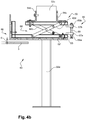
- the figure 5 illustrates a second embodiment of the invention in which the adjusting element is a lifting device 70.
- the lifting device 70 is placed under the movable part 60, and in particular under the horizontal plate 62 'and on a support 71 fixed to feet 32a.
- the mobile connecting elements 66 are the connecting rods 42a-d but, according to other possible alternative embodiments, they can be any type of element making it possible to connect the mobile part 60 to the fixed part 50 so as to be able to modify the distance between the mobile part 60 and the fixed part 50 in the direction Z.
- the lifting device 70 comprises a support rod 72 hingedly connected to a lifting rod 74 comprising a contact member 75 which is in contact with the horizontal plate 62 'and which supports the latter in a vertical direction.
- a lifting rod 77 connected in an articulated manner to the connecting rod 74, makes it possible to modify the height of the mobile part 60 and therefore to modulate the distance "d".
- the contact member 75 rises and lifts the movable part 60 which approaches the fixed part 50, thus increasing the distance "d".
- the contact member 75 descends, thus causing a lowering of the movable part 60 which moves away from the fixed part 50, thus reducing the distance "d".
- the contact member 75 is a rounded head but this member can take any type of shape.
- the lifting device 70 can be, for example, a jack or any type of device which can be placed between the mobile part 60 and the support 71 and making it possible to modify the height of the mobile part 60.
- the adjustment is carried out manually, however, according to other possible alternative embodiments, the adjustment can be carried out using a motorized system.
- the adjustment device may not include a mobility element.
- the adjustment device can, for example, only comprise the adjustment element 65 or the lifting device 70.
Landscapes
- Engineering & Computer Science (AREA)
- Mechanical Engineering (AREA)
- Textile Engineering (AREA)
- General Engineering & Computer Science (AREA)
- Nonwoven Fabrics (AREA)
Applications Claiming Priority (1)
| Application Number | Priority Date | Filing Date | Title |
|---|---|---|---|
| FR1872461A FR3089510B1 (fr) | 2018-12-06 | 2018-12-06 | Dispositif de réglage pour machine de fabrication de matelas en fibres minérales |
Publications (1)
| Publication Number | Publication Date |
|---|---|
| EP3663626A1 true EP3663626A1 (de) | 2020-06-10 |
Family
ID=67660140
Family Applications (1)
| Application Number | Title | Priority Date | Filing Date |
|---|---|---|---|
| EP19214257.8A Withdrawn EP3663626A1 (de) | 2018-12-06 | 2019-12-06 | Einstellvorrichtung für maschine zur herstellung von mineralfasermatten |
Country Status (2)
| Country | Link |
|---|---|
| EP (1) | EP3663626A1 (de) |
| FR (1) | FR3089510B1 (de) |
Cited By (2)
| Publication number | Priority date | Publication date | Assignee | Title |
|---|---|---|---|---|
| CN113932092A (zh) * | 2021-10-21 | 2022-01-14 | 南通福美新材料有限公司 | 一种超大型纳米微孔绝热板生产设备 |
| IT202000023782A1 (it) * | 2020-10-09 | 2022-04-09 | Stm Tech S R L | Apparecchiatura per la produzione continua di un materasso comprendente fibre minerali agglomerate |
Citations (3)
| Publication number | Priority date | Publication date | Assignee | Title |
|---|---|---|---|---|
| US3553053A (en) * | 1968-01-02 | 1971-01-05 | Owens Corning Fiberglass Corp | Movable wall construction for glass fiber forming hoods and the like |
| FR2079325A1 (de) * | 1970-02-09 | 1971-11-12 | Owens Corning Fiberglass Corp | |
| US5013229A (en) * | 1988-12-08 | 1991-05-07 | G. Siempelkamp Gmbh & Co. | Mat-making apparatus for particleboard manufacture |
-
2018
- 2018-12-06 FR FR1872461A patent/FR3089510B1/fr active Active
-
2019
- 2019-12-06 EP EP19214257.8A patent/EP3663626A1/de not_active Withdrawn
Patent Citations (3)
| Publication number | Priority date | Publication date | Assignee | Title |
|---|---|---|---|---|
| US3553053A (en) * | 1968-01-02 | 1971-01-05 | Owens Corning Fiberglass Corp | Movable wall construction for glass fiber forming hoods and the like |
| FR2079325A1 (de) * | 1970-02-09 | 1971-11-12 | Owens Corning Fiberglass Corp | |
| US5013229A (en) * | 1988-12-08 | 1991-05-07 | G. Siempelkamp Gmbh & Co. | Mat-making apparatus for particleboard manufacture |
Cited By (3)
| Publication number | Priority date | Publication date | Assignee | Title |
|---|---|---|---|---|
| IT202000023782A1 (it) * | 2020-10-09 | 2022-04-09 | Stm Tech S R L | Apparecchiatura per la produzione continua di un materasso comprendente fibre minerali agglomerate |
| WO2022074106A1 (en) * | 2020-10-09 | 2022-04-14 | Stm Technologies S.R.L. | Apparatus for the continuous production of a mattress comprising agglomerated mineral fibres |
| CN113932092A (zh) * | 2021-10-21 | 2022-01-14 | 南通福美新材料有限公司 | 一种超大型纳米微孔绝热板生产设备 |
Also Published As
| Publication number | Publication date |
|---|---|
| FR3089510B1 (fr) | 2020-11-13 |
| FR3089510A1 (fr) | 2020-06-12 |
Similar Documents
| Publication | Publication Date | Title |
|---|---|---|
| EP0438328B1 (de) | Vorrichtung zur Verbindung durch Pressen von Verbundglasscheiben | |
| EP2701892B2 (de) | Verfahren zur herstellung eines objekts durch pulververfestigung mittels eines laserstrahls mit einsatz eines elements zur absorption von deformationen | |
| EP3663626A1 (de) | Einstellvorrichtung für maschine zur herstellung von mineralfasermatten | |
| FR2779161A1 (fr) | Mecanisme de commande de hauteur pour plaque d'arasement d'une structure de table de finisseur | |
| FR2554436A1 (fr) | Bombage de volumes de verre sur lit de conformation constitue d'elements tournants | |
| FR2720682A1 (fr) | Commande de système de ballast réglable dans un dispositif d'encollage de double-face. | |
| EP0566497B1 (de) | Düsenmesser zur Steuerung der Beschichtungsdicke eines Metallüberzugs | |
| FR2498218A1 (fr) | Machine pour le bourrage et le nivellement d'une voie ferree, comprenant un dispositif de stabilisation | |
| EP0574874B1 (de) | Vorrichtung zum Regeln des Abstands zwischen einem Klebestoffauftragszylinder und einem Bandzuführzylinder | |
| FR2578872A1 (fr) | Outil de moulage tracte pour la realisation de dalles de beton sur le sol | |
| FR2722654A1 (fr) | Faconneuse horizontale de patons | |
| CA2618546A1 (fr) | Convoyeur a air pour articles suspendus avec poutre porteuse pour accessoires de convoyage | |
| FR2951900A1 (fr) | Train de roulement a roue palpeuse pour machine agricole | |
| EP2993267B1 (de) | Verschalungssystem, das eine perfektionierte dehnungsfuge umfasst | |
| EP0415827B1 (de) | Vorrichtung zum Biegen von Glasscheiben | |
| FR2798053A1 (fr) | Dispositif pour soulever un sommier avec sa literie | |
| EP3048891B1 (de) | Trägerplatte für backwaren | |
| EP0225198A1 (de) | Vorrichtung zum Streckrichten eines metallischen Bandes | |
| FR3127514A1 (fr) | Dispositif de supportage d’un tube d’enroulement de volet roulant dans un coffre de volet roulant, sous-ensemble de montage et installation de protection comprenant un tel dispositif de supportage et méthode d’assemblage associée | |
| EP0574873B1 (de) | Einseitige Wellpappen-Herstellungsmaschine | |
| FR2624849A1 (fr) | Dispositif de reglage de l'espace entre deux plaques, en particulier un moule de profilage ajustable pour la fabrication de pare-brise | |
| FR2964126A1 (fr) | Table de moulage pour la realisation in situ de dalles porteuses de plancher | |
| FR3074820A1 (fr) | Ossature pour module de construction pour mur, plancher ou plafond, module de construction correspondant et machine de remplissage pour celui-ci | |
| FR2737833A1 (fr) | Dispositif de chauffage electrique et son procede de fabrication | |
| EP0172948B1 (de) | Flachstrickmaschine |
Legal Events
| Date | Code | Title | Description |
|---|---|---|---|
| PUAI | Public reference made under article 153(3) epc to a published international application that has entered the european phase |
Free format text: ORIGINAL CODE: 0009012 |
|
| STAA | Information on the status of an ep patent application or granted ep patent |
Free format text: STATUS: THE APPLICATION HAS BEEN PUBLISHED |
|
| AK | Designated contracting states |
Kind code of ref document: A1 Designated state(s): AL AT BE BG CH CY CZ DE DK EE ES FI FR GB GR HR HU IE IS IT LI LT LU LV MC MK MT NL NO PL PT RO RS SE SI SK SM TR |
|
| AX | Request for extension of the european patent |
Extension state: BA ME |
|
| STAA | Information on the status of an ep patent application or granted ep patent |
Free format text: STATUS: REQUEST FOR EXAMINATION WAS MADE |
|
| 17P | Request for examination filed |
Effective date: 20201208 |
|
| RBV | Designated contracting states (corrected) |
Designated state(s): AL AT BE BG CH CY CZ DE DK EE ES FI FR GB GR HR HU IE IS IT LI LT LU LV MC MK MT NL NO PL PT RO RS SE SI SK SM TR |
|
| STAA | Information on the status of an ep patent application or granted ep patent |
Free format text: STATUS: EXAMINATION IS IN PROGRESS |
|
| 17Q | First examination report despatched |
Effective date: 20210202 |
|
| P01 | Opt-out of the competence of the unified patent court (upc) registered |
Effective date: 20230530 |
|
| GRAP | Despatch of communication of intention to grant a patent |
Free format text: ORIGINAL CODE: EPIDOSNIGR1 |
|
| STAA | Information on the status of an ep patent application or granted ep patent |
Free format text: STATUS: GRANT OF PATENT IS INTENDED |
|
| INTG | Intention to grant announced |
Effective date: 20240417 |
|
| STAA | Information on the status of an ep patent application or granted ep patent |
Free format text: STATUS: THE APPLICATION IS DEEMED TO BE WITHDRAWN |
|
| 18D | Application deemed to be withdrawn |
Effective date: 20240820 |