EP3663617B1 - Valve - Google Patents
Valve Download PDFInfo
- Publication number
- EP3663617B1 EP3663617B1 EP18842043.4A EP18842043A EP3663617B1 EP 3663617 B1 EP3663617 B1 EP 3663617B1 EP 18842043 A EP18842043 A EP 18842043A EP 3663617 B1 EP3663617 B1 EP 3663617B1
- Authority
- EP
- European Patent Office
- Prior art keywords
- valve
- valve core
- sealing portion
- positioning member
- core
- Prior art date
- Legal status (The legal status is an assumption and is not a legal conclusion. Google has not performed a legal analysis and makes no representation as to the accuracy of the status listed.)
- Active
Links
- 238000007789 sealing Methods 0.000 claims description 69
- 230000005540 biological transmission Effects 0.000 claims description 49
- 238000000034 method Methods 0.000 claims description 9
- 230000002093 peripheral effect Effects 0.000 claims description 6
- 230000001360 synchronised effect Effects 0.000 claims description 6
- 230000003068 static effect Effects 0.000 claims description 4
- 230000003321 amplification Effects 0.000 claims description 3
- 238000003199 nucleic acid amplification method Methods 0.000 claims description 3
- 230000013011 mating Effects 0.000 description 13
- 239000007788 liquid Substances 0.000 description 8
- 238000004140 cleaning Methods 0.000 description 3
- 241000894006 Bacteria Species 0.000 description 2
- 238000011109 contamination Methods 0.000 description 2
- 238000009434 installation Methods 0.000 description 2
- 239000000126 substance Substances 0.000 description 2
- 230000006835 compression Effects 0.000 description 1
- 238000007906 compression Methods 0.000 description 1
- 238000010586 diagram Methods 0.000 description 1
- 230000000694 effects Effects 0.000 description 1
- 238000003825 pressing Methods 0.000 description 1
Images


Classifications
-
- F—MECHANICAL ENGINEERING; LIGHTING; HEATING; WEAPONS; BLASTING
- F16—ENGINEERING ELEMENTS AND UNITS; GENERAL MEASURES FOR PRODUCING AND MAINTAINING EFFECTIVE FUNCTIONING OF MACHINES OR INSTALLATIONS; THERMAL INSULATION IN GENERAL
- F16K—VALVES; TAPS; COCKS; ACTUATING-FLOATS; DEVICES FOR VENTING OR AERATING
- F16K1/00—Lift valves or globe valves, i.e. cut-off apparatus with closure members having at least a component of their opening and closing motion perpendicular to the closing faces
- F16K1/16—Lift valves or globe valves, i.e. cut-off apparatus with closure members having at least a component of their opening and closing motion perpendicular to the closing faces with pivoted closure-members
- F16K1/18—Lift valves or globe valves, i.e. cut-off apparatus with closure members having at least a component of their opening and closing motion perpendicular to the closing faces with pivoted closure-members with pivoted discs or flaps
- F16K1/20—Lift valves or globe valves, i.e. cut-off apparatus with closure members having at least a component of their opening and closing motion perpendicular to the closing faces with pivoted closure-members with pivoted discs or flaps with axis of rotation arranged externally of valve member
- F16K1/2042—Special features or arrangements of the sealing
- F16K1/2057—Special features or arrangements of the sealing the sealing being arranged on the valve seat
-
- F—MECHANICAL ENGINEERING; LIGHTING; HEATING; WEAPONS; BLASTING
- F16—ENGINEERING ELEMENTS AND UNITS; GENERAL MEASURES FOR PRODUCING AND MAINTAINING EFFECTIVE FUNCTIONING OF MACHINES OR INSTALLATIONS; THERMAL INSULATION IN GENERAL
- F16K—VALVES; TAPS; COCKS; ACTUATING-FLOATS; DEVICES FOR VENTING OR AERATING
- F16K1/00—Lift valves or globe valves, i.e. cut-off apparatus with closure members having at least a component of their opening and closing motion perpendicular to the closing faces
- F16K1/16—Lift valves or globe valves, i.e. cut-off apparatus with closure members having at least a component of their opening and closing motion perpendicular to the closing faces with pivoted closure-members
- F16K1/18—Lift valves or globe valves, i.e. cut-off apparatus with closure members having at least a component of their opening and closing motion perpendicular to the closing faces with pivoted closure-members with pivoted discs or flaps
- F16K1/20—Lift valves or globe valves, i.e. cut-off apparatus with closure members having at least a component of their opening and closing motion perpendicular to the closing faces with pivoted closure-members with pivoted discs or flaps with axis of rotation arranged externally of valve member
- F16K1/2007—Lift valves or globe valves, i.e. cut-off apparatus with closure members having at least a component of their opening and closing motion perpendicular to the closing faces with pivoted closure-members with pivoted discs or flaps with axis of rotation arranged externally of valve member specially adapted operating means therefor
-
- F—MECHANICAL ENGINEERING; LIGHTING; HEATING; WEAPONS; BLASTING
- F16—ENGINEERING ELEMENTS AND UNITS; GENERAL MEASURES FOR PRODUCING AND MAINTAINING EFFECTIVE FUNCTIONING OF MACHINES OR INSTALLATIONS; THERMAL INSULATION IN GENERAL
- F16K—VALVES; TAPS; COCKS; ACTUATING-FLOATS; DEVICES FOR VENTING OR AERATING
- F16K1/00—Lift valves or globe valves, i.e. cut-off apparatus with closure members having at least a component of their opening and closing motion perpendicular to the closing faces
- F16K1/16—Lift valves or globe valves, i.e. cut-off apparatus with closure members having at least a component of their opening and closing motion perpendicular to the closing faces with pivoted closure-members
- F16K1/18—Lift valves or globe valves, i.e. cut-off apparatus with closure members having at least a component of their opening and closing motion perpendicular to the closing faces with pivoted closure-members with pivoted discs or flaps
- F16K1/20—Lift valves or globe valves, i.e. cut-off apparatus with closure members having at least a component of their opening and closing motion perpendicular to the closing faces with pivoted closure-members with pivoted discs or flaps with axis of rotation arranged externally of valve member
- F16K1/2014—Shaping of the valve member
-
- F—MECHANICAL ENGINEERING; LIGHTING; HEATING; WEAPONS; BLASTING
- F16—ENGINEERING ELEMENTS AND UNITS; GENERAL MEASURES FOR PRODUCING AND MAINTAINING EFFECTIVE FUNCTIONING OF MACHINES OR INSTALLATIONS; THERMAL INSULATION IN GENERAL
- F16K—VALVES; TAPS; COCKS; ACTUATING-FLOATS; DEVICES FOR VENTING OR AERATING
- F16K1/00—Lift valves or globe valves, i.e. cut-off apparatus with closure members having at least a component of their opening and closing motion perpendicular to the closing faces
- F16K1/24—Lift valves or globe valves, i.e. cut-off apparatus with closure members having at least a component of their opening and closing motion perpendicular to the closing faces with valve members that, on opening of the valve, are initially lifted from the seat and next are turned around an axis parallel to the seat
-
- F—MECHANICAL ENGINEERING; LIGHTING; HEATING; WEAPONS; BLASTING
- F16—ENGINEERING ELEMENTS AND UNITS; GENERAL MEASURES FOR PRODUCING AND MAINTAINING EFFECTIVE FUNCTIONING OF MACHINES OR INSTALLATIONS; THERMAL INSULATION IN GENERAL
- F16K—VALVES; TAPS; COCKS; ACTUATING-FLOATS; DEVICES FOR VENTING OR AERATING
- F16K31/00—Actuating devices; Operating means; Releasing devices
- F16K31/44—Mechanical actuating means
- F16K31/52—Mechanical actuating means with crank, eccentric, or cam
- F16K31/524—Mechanical actuating means with crank, eccentric, or cam with a cam
- F16K31/52408—Mechanical actuating means with crank, eccentric, or cam with a cam comprising a lift valve
- F16K31/52441—Mechanical actuating means with crank, eccentric, or cam with a cam comprising a lift valve with a pivoted disc or flap
-
- F—MECHANICAL ENGINEERING; LIGHTING; HEATING; WEAPONS; BLASTING
- F16—ENGINEERING ELEMENTS AND UNITS; GENERAL MEASURES FOR PRODUCING AND MAINTAINING EFFECTIVE FUNCTIONING OF MACHINES OR INSTALLATIONS; THERMAL INSULATION IN GENERAL
- F16K—VALVES; TAPS; COCKS; ACTUATING-FLOATS; DEVICES FOR VENTING OR AERATING
- F16K31/00—Actuating devices; Operating means; Releasing devices
- F16K31/44—Mechanical actuating means
- F16K31/53—Mechanical actuating means with toothed gearing
- F16K31/535—Mechanical actuating means with toothed gearing for rotating valves
Definitions
- the present invention relates to valves, and more particularly to valves used in logistics transportation equipment
- Chinese patent CN1023225368 discloses a low-torque ball valve. When the valve is closed and the valve is cleaned from the front, some of the cleaning liquid will be remained between the valve core and the valve seat positioning device. As a result, residual cleaning liquid and other harmful substances will breed bacteria and cause food contamination
- US 3 650 508 A relates to a valve adapted for bi-directional thermally responsive sealing means having a pair of spaced bead-like projections for engaging a valve disc in leak-proof fashion.
- WO 2017/125075 A1 relates to a storage container, and more particularly to a valve.
- US 2015/083955 A1 relates to bi-directional rotary valves, and more particularly to rotary valves adapted to operate at cryogenic temperatures with enhanced fluidic sealing capability.
- the object of the present application is to provide a valve which can reduce or even eliminate the residue of liquid in the valve.
- the present application provides a valve according to independent claim 1 and including a valve body, an inner valve seat and a valve core, wherein the valve core is installed in the valve body, and the inner valve seat is installed in the valve body, wherein the inner valve seat has an annular body and a sealing structure, wherein the sealing structure is arranged such that when the valve is in a closed state, the sealing structure seals and / or fills gaps formed among the valve body, the inner valve seat, and the valve core.
- the sealing structure extends inwards along the entire inner peripheral surface of the annular body and is provided with an elastic portion and a first sealing portion in sequence, wherein the first sealing portion is configured to abut the side of the valve core facing the inner valve seat when the valve is in a closed state.
- the first sealing portion protrudes from a distal end of the elastic portion toward the valve core.
- the sealing structure extends radially inwards along the entire inner peripheral surface of the annular body.
- the inner valve seat is further provided with a main sealing portion, wherein the main sealing portion is provided on the annular body and is arranged to abut against the side of the valve core facing the inner valve seat when the valve is in a closed state, and the position where the main sealing portion abuts the valve core is located radially outward compared with the position where the first sealing portion abuts the valve core.
- a second sealing portion and a third sealing portion are provided on a side of the valve core facing the inner valve seat, wherein the second sealing portion is located radially outward with respect to the third sealing portion, and when the valve is in a closed state, the second sealing portion is engaged with the main sealing portion, and the third sealing portion is engaged with the first sealing portion.
- valve core is hinged to the valve body and the valve further includes a handle and a valve stem, wherein the handle is provided with a driving gear, the valve stem is provided with a driven gear, and the driving gear mates with the driven gear, so that rotation of the handle drives the valve stem to rotate, which in turn drives the valve core to rotate.
- the valve further includes a driving member, wherein the driving member is fixedly connected to the valve stem, and a connecting portion is provided on the valve core, wherein the connecting portion is provided with a first groove, the driving member is mounted in the first groove and is provided with a shoulder, and a shoulder mating surface is provided on the first groove, wherein the rotation of the valve stem drives the driving member to rotate and cause the opening of the valve through cooperation between the shoulder and the shoulder mating surface.
- the driving member is provided with a first valve stem mounting hole, and two sides of the first groove of the connecting portion are provided with second valve stem mounting holes, and the valve stem is inserted into the first valve stem mounting hole and the second valve stem mounting hole, so that the rotation of the valve stem drives the driving member to rotate.
- a valve core mounting portion is provided in the valve body, wherein the valve core mounting portion is provided with a second groove, and two sides of the second groove are provided with valve stem positioning holes, wherein the connecting portion of the valve core is installed in the second groove, and the valve stem passes through the valve stem positioning hole, the first valve stem mounting hole, the second valve stem mounting hole, and the connecting portion so that the valve core is rotatably installed in the valve body.
- valve core is hinged to the valve body and the valve further includes a handle and a valve stem, wherein the handle and the valve stem have different axes of rotation, the handle and the valve stem have a transmission relationship of synchronous rotation, and the rotation of the handle transmits a synchronous rotation with angle amplification to the valve stem, so as to drive the valve core to rotate.
- the handle is provided with a driving gear
- the valve stem is provided with a driven gear
- the driving gear mates with the driven gear, so that rotation of the handle drives the valve stem to rotate, and then drives the valve core to rotate.
- the valve further includes a driving member, wherein the driving member is fixedly connected to the valve stem, a connecting portion is provided on the valve core, the connecting portion is provided with a first groove, the driving member is mounted in the first groove and is provided with a shoulder, and a shoulder mating surface is provided in the first groove, wherein the rotation of the valve stem drives the driving member to rotate and cause the opening of the valve through cooperation between the shoulder and the shoulder mating surface.
- the driving member is provided with a first valve stem mounting hole, and two sides of the first groove of the connecting portion are provided with second valve stem mounting holes, and the valve stem is inserted into the first valve stem mounting hole and the second valve stem mounting hole, so that the rotation of the valve stem drives the driving member to rotate.
- a valve core mounting portion is provided in the valve body, wherein the valve core mounting portion is provided with a second groove, and two sides of the second groove are provided with valve stem positioning holes, wherein the connecting portion of the valve core is installed in the second groove, and the valve stem passes through the valve stem positioning hole, the first valve stem mounting hole, the second valve stem mounting hole, and the connecting portion so that the valve core is rotatably installed in the valve body.
- the valve core is hinged to the valve body, and the valve further includes a driving member, a positioning member, and an elastic member, wherein the positioning member is movably mounted on the valve core, the elastic member is installed between the positioning member and the valve core, and the disengageable relationship between the driving member and the positioning member imparts the valve with the following three transmission relationships during the closing process: the driving member cooperates with the positioning member to form a relatively static first transmission relationship under the elastic action of the elastic member, and drives the valve core to rotate to close the valve core; when the first transmission relationship ends, the driving member and the positioning member are switched from a first transmission relationship to a second transmission relationship, in which the driving member presses the positioning member to cause the positioning member to move with respect to the valve core; and when the second transmission relationship ends, the driving member and the positioning member are switched from the second transmission relationship to a third transmission relationship between the driving member and the valve core, in which the driving member controls the positioning member in an extended state so that the positioning member is always in a state of cooperating with the valve body,
- valve core is hinged to the valve body and the valve further includes a handle and a valve stem, wherein the handle is provided with a driving gear, the valve stem is provided with a driven gear, and the driving gear mates with the driven gear, so that rotation of the handle drives the valve stem to rotate, and further drives the valve core to rotate.
- valve core is hinged to the valve body and the valve further includes a handle and a valve stem, wherein the handle and the valve stem have different axes of rotation, the handle and the valve stem have a transmission relationship of synchronous rotation, and the rotation of the handle transmits a synchronous rotation with angle amplification to the valve stem, so as to drive the valve core to rotate.
- the valve core is hinged to the valve body, and the valve further includes a driving member, a positioning member, and an elastic member, wherein the positioning member is movably mounted on the valve core, the elastic member is installed between the positioning member and the valve core, and the disengageable relationship between the driving member and the positioning member imparts the valve with the following three transmission relationships during the closing process: the driving member cooperates with the positioning member to form a relatively static first transmission relationship under the elastic action of the elastic member, and drives the valve core to rotate to close the valve core; when the first transmission relationship ends, the driving member and the positioning member are switched from a first transmission relationship to a second transmission relationship, in which the driving member presses the positioning member to cause the positioning member to move with respect to the valve core; and when the second transmission relationship ends, the driving member and the positioning member are switched from the second transmission relationship to a third transmission relationship between the driving member and the valve core, in which the driving member controls the positioning member to keep in an extended state so that the positioning member is always in a state of cooperating with the valve
- valve of the present application is provided with a sealing structure that prevents liquid from entering the gap among the valve body, the valve core, and the inner valve seat, it can greatly reduce the liquid residue inside the valve and reduce pollution.
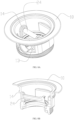
- the valve 100 includes a valve body 10, a valve core assembly 20, a valve stem 30, a handle 40, an outer valve seat 50, an inner valve seat 60, a flange 70, and a cover 80.
- the valve core assembly 20 includes a valve core 21, a driving member 22, an elastic member 23, and a positioning member 24.
- the valve core assembly 20 is installed in the valve body 10, and the valve core 21 is hinged to the valve body 10.
- the outer valve seat 50 is provided between the valve body 10 and the cover 80.
- the inner valve seat 60 is disposed between the valve core 21 and the valve body 10. In the closed state, the inner valve seat cooperates with the valve core so that the space formed among the valve core, the valve body and the inner valve seat is at least partially filled and / or fully sealed.
- the cover 80 is provided at the outlet end of the valve body 10.
- the flange 70 is provided at the inlet end of the valve body 10.
- a flow channel is formed between the inlet end and the outlet end of the valve body.
- the flow channel has an axis extending from the inlet end to the outlet end.
- the handle 40 is provided with a driving gear 41, and the valve stem 30 is provided with a driven gear 31.
- the driving gear 41 is engaged with the driven gear 31, so that the rotation of the valve stem 30 can be driven by the rotation of the handle 40.
- valve core assembly according to an embodiment of the present application with reference to FIGS. 3-6B .
- the driving member 22 is provided with a shoulder 221, a locking cam 222, a control cam 223, and a first valve stem mounting hole 224.
- the control cam 223 is located in the middle of the driving member 22 and is used to engage with a cam mating surface 241 provided on the positioning member 24 so as to drive the positioning member to slide through the rotation of the driving member.
- the shoulder 221 is provided on both sides of the control cam 223 and is used to engage with the shoulder mating surface 213 of the valve core 21 so as to realize valve opening.
- the locking cams 222 are located behind the shoulder 221 and are used to engage with locking projections 214 of the valve core 21 so as to achieve a third transmission relationship.
- the first valve stem mounting hole 224 is formed through the driving member 22, and the valve stem 30 can be inserted into the first valve stem mounting hole 224, so that the driving member 22 can be driven to rotate by the rotation of the valve stem 30.
- the cooperation relationship among parts of the driving member 22, the valve core 21, and the positioning member 24 will be described in detail below.
- the valve core 21 is provided with a guiding portion 210.
- the guiding portion 210 is a through hole laterally in the valve core 21.
- the positioning member 24 can be inserted into the guiding portion 210 and can slide in the guiding portion 210.
- the valve core 21 is further provided with a connecting portion 211.
- the connecting portion 211 is formed by integrally protruding outward from an edge of the valve core 21 at one end of the guiding portion 210.
- a first groove 212 is provided in a middle portion of the connecting portion 211.
- a locking boss 214 is provided at the bottom of the first groove 212.
- Second valve stem mounting holes 215 are provided on both sides of the first groove 212.
- the first groove 212 is used for mounting the driving member 22.
- the locking boss 214 is used to engage with the locking cam 222 of the driving member 22.
- the second valve stem mounting hole 215 is used for mounting the valve stem 30.
- the shoulder mating surface 213 is used for engaging with the control cam 223 of the shoulder 221.
- the diameter of the second valve stem mounting hole 215 is larger than the outer diameter of the valve stem 30, so that the valve stem 30 can be rotated in the second valve stem mounting hole 215, which will be described in detail below.
- a second sealing portion 216 and a third sealing portion 217 are provided on a side of the valve core 21 opposite to the side on which the guiding portion is provided, that is, a side 26 facing the inner valve seat 60.
- the second sealing portion 216 is located radially outward with respect to the third sealing portion 217.
- the positioning member 24 is substantially cylindrical in shape.
- a protruding block 240 is provided on one end of the positioning member 24.
- a cam mating surface 241 is provided at the end of the protruding block 240. The cam mating surface 241 is in contact with the control cam 223 of the driving member 22, so that the positioning member 24 is driven to move relative to the valve core 21 by the rotation of the driving member 22.
- Flanges 242 are provided on both sides of the protruding block. The side of the flange 242 facing the protruding block is provided with an arc surface 243 for giving way to the locking cam 222 of the driving member 22.
- the positioning member 24 is further provided with a limiting step 244.
- the limiting step 244 limits the elastic member 23 laterally, so that the elastic member 23 can applies a force on the positioning member 24 toward the driving member 22, so that the elastic member 23 can drive the positioning member 24 out of the valve body to unlock.
- the guiding portion 210 is a through hole provided in the valve core 21 in the radial direction.
- the guiding portion 210 can also be provided in other ways.
- the elastic member 23 is sleeved over the positioning member 24 and is laterally limited by the limiting step 244 at one end.
- the driving member 22 is installed in the first groove 212 of the valve core 21 such that the first valve stem mounting hole 224 of the driving member 22 is aligned with the second valve stem mounting hole 215.
- valve stem 30 is passed through the second valve stem mounting hole 215 on one side and is passed through the first valve stem mounting hole 224, and then is passed through the second valve stem mounting hole 215 on the other side, so as to hinge the valve core 21 to the driving member 22, and movably restrict the positioning member 24 in the guiding portion 210 of the valve core 21, wherein the valve stem 30 is fixedly connected to the driving member 22, that is, the valve stem 30 cannot rotate in the first valve stem mounting hole 224 of the driving member 22, and the valve stem 30 can rotate in the second valve stem mounting hole 215 of the valve core 21, thereby the rotation of the valve stem 30 can drive the rotation of the driving member 22, so that the rotation of the valve stem 30 drives the driving member 22 to rotate and drives the positioning member 24 to move relative to the valve core 21.
- FIG. 7-7B illustrate a structure of an inner valve seat 60 according to an embodiment of the present application.
- the inner valve seat 60 has a annular body 601 and a sealing structure 603 extending inwards from the inner peripheral surface of the annular body.
- the sealing structure 603 extends radially inward along the entire inner peripheral surface of the annular body and is provided with an elastic portion 604 and a first sealing portion 605 in sequence.
- the sealing structure 603 integrally extends from the inner peripheral surface of the annular body 601.
- the elastic portion 604 is an annular member having a smaller thickness than the annular body.
- the first sealing portion 605 protrudes from the distal end of the elastic portion 604 toward the valve core, so that the first sealing portion is substantially hook-shaped as viewed in the cross-sectional view of FIG. 7A .
- the inner valve seat 60 is further provided with a main sealing portion 602.
- the main sealing portion 602 is located inside the top surface of the annular body 601.
- the top surface of the annular body refers to a side of the annular body that is the same as the protruding direction of the first sealing portion 605.
- the main sealing portion 602 and the first sealing portion 605 abut against the side of the valve core 21 facing the inner valve seat 60, that is, abut against the second sealing portion 216 and the third sealing portion 217 of the valve core, respectively.
- FIGS. 8-8C illustrate the structure and installation diagram of the valve stem, the valve body, the positioning member, and the driving member.
- a valve body mounting portion 11 is provided in the valve body 10.
- the valve core mounting portion 11 is provided with a second groove 12.
- Valve stem positioning holes 13 are provided on both sides of the second groove 12, and the connecting portion 211 of the valve core 21 is installed in the second groove 12.
- valve stem 30 is passed through valve stem positioning holes 13 on one side of the valve body 10, is passed through the second valve stem mounting hole 215 on one side of the connecting portion 211, is passed through the first valve stem mounting hole 224 on the driving member 22, and then is passed through the second valve stem mounting hole 215 on the other side of the connecting portion 211, and finally is passed through the valve body positioning hole 13 on the other side of the valve body 10 so as to rotatably connect the valve core 21 to the valve body 10.
- a positioning member locking portion 14 is further provided on the inner side wall of the valve body 10, and the positioning member locking portion 14 is a groove.
- the positioning member locking portion 14 is used to limit the positioning member 24 in vertical direction, so that when the positioning member 24 is in place, the positioning member 24 is locked by the positioning member locking portion 14, which will be described in detail below.
- FIGS. 9-13A illustrate a transmission relationship of the valve of the present application during a closing process.
- Figs. 9-9A show the valve in an open state
- Figs. 10-10A show the first transmission relationship
- Figs. 11-12A show the second transmission relationship
- Figs. 13-13A show the third transmission relationship.
- the driving member 22 cooperates with the positioning member 24 through the elasticity of the elastic member 23 to form a relatively static first transmission relationship, and drives the valve core 21 to rotate, thus close the valve core 21.
- the positioning element 24 applies a force to the valve core 21 to close the valve core 21.
- the driving member 22 and the positioning member 24 are switched from the first transmission relationship to the second transmission relationship.
- the driving member 22 presses the positioning member 24 to cause the positioning member 24 to move relative to the valve core 21.
- the control cam 223 on the driving member 22 engages with the cam mating surface 241 on the positioning member 24, so that the positioning member 24 is driven by the downward rotation of the control cam 223 and moves laterally in the positioning member guiding portion 210 of the valve core 21 against the elastic force of the elastic member 23 until the front end of the positioning member 24 reaches below the positioning member locking portion 14 of the valve body 10, as shown in FIG. 12 .
- the edge of the control cam 223 contact with the bottom of the first groove 212 of the valve core 21.
- the driving member 22 and the positioning member 24 are switched from the second transmission relationship to the third transmission relationship between the driving member 22 and the valve core 21.
- the positioning member 24 is controlled by the driving member 22 to be kept in an extended state, so that the positioning member 24 is always in a state of engaging with the valve body 10, and the driving member 22 presses the valve core 21 to perform a press movement toward an axis of the flow passage of the valve, thereby sealingly locking the valve core.
- the driving member 22 rotates synchronously under the driving of the valve stem 30.
- the control cam on the driving member 22 always controls the positioning member 24 to be kept in the extended state.
- the locking cam 222 on the driving member 22 engages with the locking cam 214 on the valve core 21 to apply a force to the locking cam 214 through the control cam 222, so that the driving member 22 presses the valve core 21 and the inner valve seat 60 to perform a press movement in the axis of the flow passage of the valve under the action of the locking cam 222.
- the positioning member 24 is always in an extended state, and further rotates around the fulcrum formed by the positioning member locking portion 14 of the valve body 10 until the valve stem 30 rotates into position, and the valve core 21 is locked.
- the transmission relationship of the valve opening process is opposite to the transmission relationship of the valve closing process, which can be easily understood by those skilled in the art, thus will not be described in detail herein.
- the driving member 22 realizes the force transmission through the cooperation of the shoulder 221 of the driving member 22 with the shoulder mating surface 213 on the valve core 21, that is, the shoulder 221 applies a force to the shoulder mating surface 213 to open the valve core 21.
- the positioning member is a positioning rod
- the elastic member is a compression spring
- the positioning member may also adopt other forms
- the elastic member may also adopt other elastic members such as rubber plugs, and the positioning member and the elastic member may also be formed integrally, see below embodiments.
- the positioning member and the elastic member are separate members.
- the positioning member and the elastic member may be integrally formed.
- the elastic member is provided on the positioning member, for example, by providing an elastic protruding rib on the outer periphery of the positioning member.
- the elastic protruding rib serves as an elastic member.
- a groove may be provided on the positioning member.
- An elastic member may be provided in the groove, and a stopping portion may be provided in the guiding portion, such as a stopping pin or a stopping post etc. protruding downward from the upper side wall of the guiding portion.
- the stopping portion extends into the groove and compresses the elastic member, so that when the positioning member moves relative to the driving member, the elastic member exerts an elastic force on the positioning member under the action of the stopping portion to achieve unlocking of the positioning member.
- the valve of the present application is provided with a sealing structure to seal and / or fill the gap formed between the valve body, the inner valve seat and the valve core, thereby reducing or even eliminating liquid residue in the space among the valve core, the valve body and the valve, and the sealing effect is good.
Landscapes
- Engineering & Computer Science (AREA)
- General Engineering & Computer Science (AREA)
- Mechanical Engineering (AREA)
- Mechanically-Actuated Valves (AREA)
- Lift Valve (AREA)
- Valve Housings (AREA)
- Sliding Valves (AREA)
Applications Claiming Priority (2)
| Application Number | Priority Date | Filing Date | Title |
|---|---|---|---|
| CN201710653134.7A CN107420559B (zh) | 2017-08-02 | 2017-08-02 | 阀门 |
| PCT/CN2018/091813 WO2019024618A1 (zh) | 2017-08-02 | 2018-06-19 | 阀门 |
Publications (3)
| Publication Number | Publication Date |
|---|---|
| EP3663617A1 EP3663617A1 (en) | 2020-06-10 |
| EP3663617A4 EP3663617A4 (en) | 2021-04-14 |
| EP3663617B1 true EP3663617B1 (en) | 2023-12-13 |
Family
ID=60436663
Family Applications (1)
| Application Number | Title | Priority Date | Filing Date |
|---|---|---|---|
| EP18842043.4A Active EP3663617B1 (en) | 2017-08-02 | 2018-06-19 | Valve |
Country Status (6)
| Country | Link |
|---|---|
| US (1) | US11421788B2 (zh) |
| EP (1) | EP3663617B1 (zh) |
| JP (1) | JP7393796B2 (zh) |
| CN (1) | CN107420559B (zh) |
| AU (2) | AU2018311714A1 (zh) |
| WO (1) | WO2019024618A1 (zh) |
Families Citing this family (6)
| Publication number | Priority date | Publication date | Assignee | Title |
|---|---|---|---|---|
| CN107420559B (zh) * | 2017-08-02 | 2024-04-02 | 上海鸿研物流技术有限公司 | 阀门 |
| CA3090238A1 (en) * | 2019-08-16 | 2021-02-16 | Gabe Coscarella | Backwater valve |
| US11686392B2 (en) * | 2021-04-06 | 2023-06-27 | Seaworthy Innovations, LLC | Scupper valve |
| CN113187907A (zh) * | 2021-06-07 | 2021-07-30 | 西安中创云联智能科技有限公司 | 一种旋启式控制阀 |
| CN116045018B (zh) * | 2023-03-30 | 2023-07-04 | 成都中科唯实仪器有限责任公司 | 一种大口径矩形插板阀 |
| CN117927683B (zh) * | 2024-02-27 | 2024-08-06 | 五洲阀门股份有限公司 | 一种用于超低温环境下的蝶阀 |
Family Cites Families (25)
| Publication number | Priority date | Publication date | Assignee | Title |
|---|---|---|---|---|
| US2597474A (en) | 1948-09-23 | 1952-05-20 | William B Griffith | Dry pipe valve |
| DE1295218B (de) * | 1964-08-06 | 1969-05-14 | Bopp & Reuther Gmbh | Umschaltventil in einem Verbundfluessigkeitszaehler |
| US3462120A (en) * | 1966-06-27 | 1969-08-19 | Hills Mccanna Co | Ball valve |
| US3488033A (en) * | 1967-12-28 | 1970-01-06 | Hills Mccanna Co | Self-pressure relieving ball valve |
| US3650508A (en) * | 1969-02-06 | 1972-03-21 | Royal Industries | Bi-directional valve for cryogenic fluids |
| GB1305554A (zh) * | 1969-04-11 | 1973-02-07 | ||
| CH549179A (de) | 1972-03-14 | 1974-05-15 | Sulzer Ag | Gasdichte verschlussklappe. |
| CA1054126A (en) * | 1976-06-07 | 1979-05-08 | William E. Mcclurg | Groove mounted resilient valve seat having a deformable lip |
| US4176820A (en) * | 1977-07-05 | 1979-12-04 | Fmc Corporation | Pressure-sensitive temperature-responsive rotary valve for cryogenic temperatures |
| US4195815A (en) | 1978-05-30 | 1980-04-01 | Litton Industrial Products, Inc. | Bidirectional valve for cryogenic fluids |
| US4822000A (en) * | 1987-08-24 | 1989-04-18 | Rockford Controls Corporation | Eccentric segmented ball valves |
| CA2177026A1 (en) * | 1996-05-21 | 1997-11-22 | Adolf Karel Velan | Butterfly valve |
| DE10238478A1 (de) * | 2002-08-22 | 2004-03-04 | Pierburg Gmbh | Kugelventil |
| JP4322248B2 (ja) * | 2005-12-26 | 2009-08-26 | ニイガタ・ローディング・システムズ株式会社 | 偏心型バタフライ弁のシール装置 |
| US9022051B2 (en) * | 2009-06-23 | 2015-05-05 | Robert B. Chaffee | Valve for an inflatable device |
| CN102808990B (zh) * | 2012-08-16 | 2015-04-29 | 上海鸿研物流技术有限公司 | 用于中型散装容器的阀门启闭装置及容器 |
| CN103016776B (zh) * | 2012-12-07 | 2015-08-26 | 上海鸿研物流技术有限公司 | 阀芯组件及低扭矩阀门 |
| US10184568B2 (en) * | 2013-09-26 | 2019-01-22 | Saint-Gobain Performance Plastics Corporation | Bi-directional rotary valve |
| DE102014108379A1 (de) * | 2014-06-13 | 2016-01-07 | Horst Severyns | Absperrvorrichtung |
| US9816620B2 (en) * | 2014-11-19 | 2017-11-14 | Kennedy Valve Company | Butterfly valve seal retaining arrangement |
| GB2537134B (en) * | 2015-04-08 | 2017-05-10 | Schenck Process Ltd | Valve closure device for pneumatic conveying systems |
| CN109707853B (zh) * | 2016-01-22 | 2021-03-16 | 上海鸿研物流技术有限公司 | 阀门 |
| CN105864497B (zh) * | 2016-05-17 | 2018-03-13 | 单中非 | 齿轮驱动密封阀 |
| CN107420559B (zh) * | 2017-08-02 | 2024-04-02 | 上海鸿研物流技术有限公司 | 阀门 |
| CN207278903U (zh) * | 2017-08-02 | 2018-04-27 | 上海鸿研物流技术有限公司 | 阀门 |
-
2017
- 2017-08-02 CN CN201710653134.7A patent/CN107420559B/zh active Active
-
2018
- 2018-06-19 AU AU2018311714A patent/AU2018311714A1/en active Pending
- 2018-06-19 WO PCT/CN2018/091813 patent/WO2019024618A1/zh unknown
- 2018-06-19 EP EP18842043.4A patent/EP3663617B1/en active Active
- 2018-06-19 JP JP2020505373A patent/JP7393796B2/ja active Active
- 2018-06-19 AU AU2018102233A patent/AU2018102233A4/en active Active
- 2018-06-19 US US16/636,302 patent/US11421788B2/en active Active
Also Published As
| Publication number | Publication date |
|---|---|
| JP7393796B2 (ja) | 2023-12-07 |
| US20200191278A1 (en) | 2020-06-18 |
| WO2019024618A1 (zh) | 2019-02-07 |
| JP2020529562A (ja) | 2020-10-08 |
| EP3663617A1 (en) | 2020-06-10 |
| US11421788B2 (en) | 2022-08-23 |
| AU2018102233A4 (en) | 2022-02-17 |
| AU2018311714A1 (en) | 2020-03-12 |
| CN107420559A (zh) | 2017-12-01 |
| CN107420559B (zh) | 2024-04-02 |
| EP3663617A4 (en) | 2021-04-14 |
Similar Documents
| Publication | Publication Date | Title |
|---|---|---|
| EP3663617B1 (en) | Valve | |
| AU2019257395B2 (en) | Valve | |
| EP3083430B1 (en) | Sealing mechanism for beverage container | |
| US8690026B2 (en) | Fluid dispensing assembly | |
| US6220470B1 (en) | Resealable closure for open end of container | |
| US20170107030A1 (en) | Admixer-closure device for a container | |
| US11066216B2 (en) | Flip lid and container including the same | |
| EP3215438B1 (en) | Container sealing assembly | |
| CN107575629B (zh) | 阀门 | |
| CN110022718A (zh) | 能够容纳固体、液体或膏体产品的罐 | |
| JP7340287B2 (ja) | 飲料ボトル | |
| US8584909B2 (en) | Dispensing tap for beverages | |
| CN207278903U (zh) | 阀门 | |
| JP6951093B2 (ja) | キャップユニット及びキャップ付き容器 | |
| US10113662B2 (en) | Liquid dispensing faucet with pull-to-open valve element | |
| CA3139141A1 (en) | Lid for beverage container | |
| CN208463850U (zh) | 杯盖、杯体组件及料理机 | |
| KR20240030898A (ko) | 음료 용기용 뚜껑 |
Legal Events
| Date | Code | Title | Description |
|---|---|---|---|
| STAA | Information on the status of an ep patent application or granted ep patent |
Free format text: STATUS: THE INTERNATIONAL PUBLICATION HAS BEEN MADE |
|
| PUAI | Public reference made under article 153(3) epc to a published international application that has entered the european phase |
Free format text: ORIGINAL CODE: 0009012 |
|
| STAA | Information on the status of an ep patent application or granted ep patent |
Free format text: STATUS: REQUEST FOR EXAMINATION WAS MADE |
|
| 17P | Request for examination filed |
Effective date: 20200302 |
|
| AK | Designated contracting states |
Kind code of ref document: A1 Designated state(s): AL AT BE BG CH CY CZ DE DK EE ES FI FR GB GR HR HU IE IS IT LI LT LU LV MC MK MT NL NO PL PT RO RS SE SI SK SM TR |
|
| AX | Request for extension of the european patent |
Extension state: BA ME |
|
| DAV | Request for validation of the european patent (deleted) | ||
| DAX | Request for extension of the european patent (deleted) | ||
| A4 | Supplementary search report drawn up and despatched |
Effective date: 20210316 |
|
| RIC1 | Information provided on ipc code assigned before grant |
Ipc: F16K 1/20 20060101AFI20210310BHEP |
|
| STAA | Information on the status of an ep patent application or granted ep patent |
Free format text: STATUS: EXAMINATION IS IN PROGRESS |
|
| 17Q | First examination report despatched |
Effective date: 20221017 |
|
| GRAP | Despatch of communication of intention to grant a patent |
Free format text: ORIGINAL CODE: EPIDOSNIGR1 |
|
| STAA | Information on the status of an ep patent application or granted ep patent |
Free format text: STATUS: GRANT OF PATENT IS INTENDED |
|
| INTG | Intention to grant announced |
Effective date: 20230621 |
|
| GRAS | Grant fee paid |
Free format text: ORIGINAL CODE: EPIDOSNIGR3 |
|
| GRAA | (expected) grant |
Free format text: ORIGINAL CODE: 0009210 |
|
| STAA | Information on the status of an ep patent application or granted ep patent |
Free format text: STATUS: THE PATENT HAS BEEN GRANTED |
|
| AK | Designated contracting states |
Kind code of ref document: B1 Designated state(s): AL AT BE BG CH CY CZ DE DK EE ES FI FR GB GR HR HU IE IS IT LI LT LU LV MC MK MT NL NO PL PT RO RS SE SI SK SM TR |
|
| REG | Reference to a national code |
Ref country code: GB Ref legal event code: FG4D |
|
| REG | Reference to a national code |
Ref country code: CH Ref legal event code: EP |
|
| REG | Reference to a national code |
Ref country code: DE Ref legal event code: R096 Ref document number: 602018062706 Country of ref document: DE |
|
| REG | Reference to a national code |
Ref country code: IE Ref legal event code: FG4D |
|
| REG | Reference to a national code |
Ref country code: LT Ref legal event code: MG9D |
|
| PG25 | Lapsed in a contracting state [announced via postgrant information from national office to epo] |
Ref country code: LT Free format text: LAPSE BECAUSE OF FAILURE TO SUBMIT A TRANSLATION OF THE DESCRIPTION OR TO PAY THE FEE WITHIN THE PRESCRIBED TIME-LIMIT Effective date: 20231213 |
|
| REG | Reference to a national code |
Ref country code: NL Ref legal event code: MP Effective date: 20231213 |
|
| PG25 | Lapsed in a contracting state [announced via postgrant information from national office to epo] |
Ref country code: ES Free format text: LAPSE BECAUSE OF FAILURE TO SUBMIT A TRANSLATION OF THE DESCRIPTION OR TO PAY THE FEE WITHIN THE PRESCRIBED TIME-LIMIT Effective date: 20231213 |
|
| PG25 | Lapsed in a contracting state [announced via postgrant information from national office to epo] |
Ref country code: LT Free format text: LAPSE BECAUSE OF FAILURE TO SUBMIT A TRANSLATION OF THE DESCRIPTION OR TO PAY THE FEE WITHIN THE PRESCRIBED TIME-LIMIT Effective date: 20231213 Ref country code: ES Free format text: LAPSE BECAUSE OF FAILURE TO SUBMIT A TRANSLATION OF THE DESCRIPTION OR TO PAY THE FEE WITHIN THE PRESCRIBED TIME-LIMIT Effective date: 20231213 Ref country code: BG Free format text: LAPSE BECAUSE OF FAILURE TO SUBMIT A TRANSLATION OF THE DESCRIPTION OR TO PAY THE FEE WITHIN THE PRESCRIBED TIME-LIMIT Effective date: 20240313 |
|
| REG | Reference to a national code |
Ref country code: AT Ref legal event code: MK05 Ref document number: 1640699 Country of ref document: AT Kind code of ref document: T Effective date: 20231213 |
|
| PG25 | Lapsed in a contracting state [announced via postgrant information from national office to epo] |
Ref country code: NL Free format text: LAPSE BECAUSE OF FAILURE TO SUBMIT A TRANSLATION OF THE DESCRIPTION OR TO PAY THE FEE WITHIN THE PRESCRIBED TIME-LIMIT Effective date: 20231213 |
|
| PG25 | Lapsed in a contracting state [announced via postgrant information from national office to epo] |
Ref country code: SE Free format text: LAPSE BECAUSE OF FAILURE TO SUBMIT A TRANSLATION OF THE DESCRIPTION OR TO PAY THE FEE WITHIN THE PRESCRIBED TIME-LIMIT Effective date: 20231213 Ref country code: RS Free format text: LAPSE BECAUSE OF FAILURE TO SUBMIT A TRANSLATION OF THE DESCRIPTION OR TO PAY THE FEE WITHIN THE PRESCRIBED TIME-LIMIT Effective date: 20231213 Ref country code: NO Free format text: LAPSE BECAUSE OF FAILURE TO SUBMIT A TRANSLATION OF THE DESCRIPTION OR TO PAY THE FEE WITHIN THE PRESCRIBED TIME-LIMIT Effective date: 20240313 Ref country code: NL Free format text: LAPSE BECAUSE OF FAILURE TO SUBMIT A TRANSLATION OF THE DESCRIPTION OR TO PAY THE FEE WITHIN THE PRESCRIBED TIME-LIMIT Effective date: 20231213 Ref country code: LV Free format text: LAPSE BECAUSE OF FAILURE TO SUBMIT A TRANSLATION OF THE DESCRIPTION OR TO PAY THE FEE WITHIN THE PRESCRIBED TIME-LIMIT Effective date: 20231213 Ref country code: HR Free format text: LAPSE BECAUSE OF FAILURE TO SUBMIT A TRANSLATION OF THE DESCRIPTION OR TO PAY THE FEE WITHIN THE PRESCRIBED TIME-LIMIT Effective date: 20231213 |
|
| PG25 | Lapsed in a contracting state [announced via postgrant information from national office to epo] |
Ref country code: IS Free format text: LAPSE BECAUSE OF FAILURE TO SUBMIT A TRANSLATION OF THE DESCRIPTION OR TO PAY THE FEE WITHIN THE PRESCRIBED TIME-LIMIT Effective date: 20240413 |
|
| PGFP | Annual fee paid to national office [announced via postgrant information from national office to epo] |
Ref country code: GB Payment date: 20240626 Year of fee payment: 7 |
|
| PG25 | Lapsed in a contracting state [announced via postgrant information from national office to epo] |
Ref country code: AT Free format text: LAPSE BECAUSE OF FAILURE TO SUBMIT A TRANSLATION OF THE DESCRIPTION OR TO PAY THE FEE WITHIN THE PRESCRIBED TIME-LIMIT Effective date: 20231213 Ref country code: CZ Free format text: LAPSE BECAUSE OF FAILURE TO SUBMIT A TRANSLATION OF THE DESCRIPTION OR TO PAY THE FEE WITHIN THE PRESCRIBED TIME-LIMIT Effective date: 20231213 |
|
| PG25 | Lapsed in a contracting state [announced via postgrant information from national office to epo] |
Ref country code: SK Free format text: LAPSE BECAUSE OF FAILURE TO SUBMIT A TRANSLATION OF THE DESCRIPTION OR TO PAY THE FEE WITHIN THE PRESCRIBED TIME-LIMIT Effective date: 20231213 |
|
| PG25 | Lapsed in a contracting state [announced via postgrant information from national office to epo] |
Ref country code: SM Free format text: LAPSE BECAUSE OF FAILURE TO SUBMIT A TRANSLATION OF THE DESCRIPTION OR TO PAY THE FEE WITHIN THE PRESCRIBED TIME-LIMIT Effective date: 20231213 Ref country code: SK Free format text: LAPSE BECAUSE OF FAILURE TO SUBMIT A TRANSLATION OF THE DESCRIPTION OR TO PAY THE FEE WITHIN THE PRESCRIBED TIME-LIMIT Effective date: 20231213 Ref country code: RO Free format text: LAPSE BECAUSE OF FAILURE TO SUBMIT A TRANSLATION OF THE DESCRIPTION OR TO PAY THE FEE WITHIN THE PRESCRIBED TIME-LIMIT Effective date: 20231213 Ref country code: IT Free format text: LAPSE BECAUSE OF FAILURE TO SUBMIT A TRANSLATION OF THE DESCRIPTION OR TO PAY THE FEE WITHIN THE PRESCRIBED TIME-LIMIT Effective date: 20231213 Ref country code: IS Free format text: LAPSE BECAUSE OF FAILURE TO SUBMIT A TRANSLATION OF THE DESCRIPTION OR TO PAY THE FEE WITHIN THE PRESCRIBED TIME-LIMIT Effective date: 20240413 Ref country code: EE Free format text: LAPSE BECAUSE OF FAILURE TO SUBMIT A TRANSLATION OF THE DESCRIPTION OR TO PAY THE FEE WITHIN THE PRESCRIBED TIME-LIMIT Effective date: 20231213 Ref country code: CZ Free format text: LAPSE BECAUSE OF FAILURE TO SUBMIT A TRANSLATION OF THE DESCRIPTION OR TO PAY THE FEE WITHIN THE PRESCRIBED TIME-LIMIT Effective date: 20231213 Ref country code: AT Free format text: LAPSE BECAUSE OF FAILURE TO SUBMIT A TRANSLATION OF THE DESCRIPTION OR TO PAY THE FEE WITHIN THE PRESCRIBED TIME-LIMIT Effective date: 20231213 |
|
| PG25 | Lapsed in a contracting state [announced via postgrant information from national office to epo] |
Ref country code: PL Free format text: LAPSE BECAUSE OF FAILURE TO SUBMIT A TRANSLATION OF THE DESCRIPTION OR TO PAY THE FEE WITHIN THE PRESCRIBED TIME-LIMIT Effective date: 20231213 Ref country code: PT Free format text: LAPSE BECAUSE OF FAILURE TO SUBMIT A TRANSLATION OF THE DESCRIPTION OR TO PAY THE FEE WITHIN THE PRESCRIBED TIME-LIMIT Effective date: 20240415 |
|
| PG25 | Lapsed in a contracting state [announced via postgrant information from national office to epo] |
Ref country code: PT Free format text: LAPSE BECAUSE OF FAILURE TO SUBMIT A TRANSLATION OF THE DESCRIPTION OR TO PAY THE FEE WITHIN THE PRESCRIBED TIME-LIMIT Effective date: 20240415 Ref country code: PL Free format text: LAPSE BECAUSE OF FAILURE TO SUBMIT A TRANSLATION OF THE DESCRIPTION OR TO PAY THE FEE WITHIN THE PRESCRIBED TIME-LIMIT Effective date: 20231213 |
|
| REG | Reference to a national code |
Ref country code: DE Ref legal event code: R097 Ref document number: 602018062706 Country of ref document: DE |
|
| PG25 | Lapsed in a contracting state [announced via postgrant information from national office to epo] |
Ref country code: DK Free format text: LAPSE BECAUSE OF FAILURE TO SUBMIT A TRANSLATION OF THE DESCRIPTION OR TO PAY THE FEE WITHIN THE PRESCRIBED TIME-LIMIT Effective date: 20231213 |
|
| PLBE | No opposition filed within time limit |
Free format text: ORIGINAL CODE: 0009261 |
|
| STAA | Information on the status of an ep patent application or granted ep patent |
Free format text: STATUS: NO OPPOSITION FILED WITHIN TIME LIMIT |
|
| PG25 | Lapsed in a contracting state [announced via postgrant information from national office to epo] |
Ref country code: SI Free format text: LAPSE BECAUSE OF FAILURE TO SUBMIT A TRANSLATION OF THE DESCRIPTION OR TO PAY THE FEE WITHIN THE PRESCRIBED TIME-LIMIT Effective date: 20231213 |
|
| PG25 | Lapsed in a contracting state [announced via postgrant information from national office to epo] |
Ref country code: SI Free format text: LAPSE BECAUSE OF FAILURE TO SUBMIT A TRANSLATION OF THE DESCRIPTION OR TO PAY THE FEE WITHIN THE PRESCRIBED TIME-LIMIT Effective date: 20231213 Ref country code: DK Free format text: LAPSE BECAUSE OF FAILURE TO SUBMIT A TRANSLATION OF THE DESCRIPTION OR TO PAY THE FEE WITHIN THE PRESCRIBED TIME-LIMIT Effective date: 20231213 |
|
| 26N | No opposition filed |
Effective date: 20240916 |
|
| PG25 | Lapsed in a contracting state [announced via postgrant information from national office to epo] |
Ref country code: MC Free format text: LAPSE BECAUSE OF FAILURE TO SUBMIT A TRANSLATION OF THE DESCRIPTION OR TO PAY THE FEE WITHIN THE PRESCRIBED TIME-LIMIT Effective date: 20231213 |
|
| REG | Reference to a national code |
Ref country code: CH Ref legal event code: PL |