EP3663559A1 - Engine and vehicle - Google Patents
Engine and vehicle Download PDFInfo
- Publication number
- EP3663559A1 EP3663559A1 EP18841581.4A EP18841581A EP3663559A1 EP 3663559 A1 EP3663559 A1 EP 3663559A1 EP 18841581 A EP18841581 A EP 18841581A EP 3663559 A1 EP3663559 A1 EP 3663559A1
- Authority
- EP
- European Patent Office
- Prior art keywords
- cylinder
- axis
- motor
- gear
- crankshaft
- Prior art date
- Legal status (The legal status is an assumption and is not a legal conclusion. Google has not performed a legal analysis and makes no representation as to the accuracy of the status listed.)
- Granted
Links
- 230000005540 biological transmission Effects 0.000 claims description 41
- 230000013011 mating Effects 0.000 claims description 37
- 239000007858 starting material Substances 0.000 abstract description 46
- 238000005549 size reduction Methods 0.000 abstract description 14
- 230000007246 mechanism Effects 0.000 description 15
- 239000003638 chemical reducing agent Substances 0.000 description 9
- 230000001154 acute effect Effects 0.000 description 6
- 239000010705 motor oil Substances 0.000 description 6
- 239000003921 oil Substances 0.000 description 5
- 230000004044 response Effects 0.000 description 5
- 238000002485 combustion reaction Methods 0.000 description 4
- 230000009467 reduction Effects 0.000 description 3
- 239000002199 base oil Substances 0.000 description 2
- 230000008901 benefit Effects 0.000 description 1
- 230000000694 effects Effects 0.000 description 1
- 230000005674 electromagnetic induction Effects 0.000 description 1
- 239000002828 fuel tank Substances 0.000 description 1
- 229910052500 inorganic mineral Inorganic materials 0.000 description 1
- 238000000034 method Methods 0.000 description 1
- 239000011707 mineral Substances 0.000 description 1
- 239000000203 mixture Substances 0.000 description 1
- 238000005192 partition Methods 0.000 description 1
- 230000002093 peripheral effect Effects 0.000 description 1
- 239000000126 substance Substances 0.000 description 1
- 239000000725 suspension Substances 0.000 description 1
Images


Classifications
-
- B—PERFORMING OPERATIONS; TRANSPORTING
- B62—LAND VEHICLES FOR TRAVELLING OTHERWISE THAN ON RAILS
- B62M—RIDER PROPULSION OF WHEELED VEHICLES OR SLEDGES; POWERED PROPULSION OF SLEDGES OR SINGLE-TRACK CYCLES; TRANSMISSIONS SPECIALLY ADAPTED FOR SUCH VEHICLES
- B62M23/00—Transmissions characterised by use of other elements; Other transmissions
- B62M23/02—Transmissions characterised by use of other elements; Other transmissions characterised by the use of two or more dissimilar sources of power, e.g. transmissions for hybrid motorcycles
-
- B—PERFORMING OPERATIONS; TRANSPORTING
- B62—LAND VEHICLES FOR TRAVELLING OTHERWISE THAN ON RAILS
- B62M—RIDER PROPULSION OF WHEELED VEHICLES OR SLEDGES; POWERED PROPULSION OF SLEDGES OR SINGLE-TRACK CYCLES; TRANSMISSIONS SPECIALLY ADAPTED FOR SUCH VEHICLES
- B62M7/00—Motorcycles characterised by position of motor or engine
- B62M7/02—Motorcycles characterised by position of motor or engine with engine between front and rear wheels
-
- F—MECHANICAL ENGINEERING; LIGHTING; HEATING; WEAPONS; BLASTING
- F02—COMBUSTION ENGINES; HOT-GAS OR COMBUSTION-PRODUCT ENGINE PLANTS
- F02B—INTERNAL-COMBUSTION PISTON ENGINES; COMBUSTION ENGINES IN GENERAL
- F02B61/00—Adaptations of engines for driving vehicles or for driving propellers; Combinations of engines with gearing
- F02B61/02—Adaptations of engines for driving vehicles or for driving propellers; Combinations of engines with gearing for driving cycles
-
- F—MECHANICAL ENGINEERING; LIGHTING; HEATING; WEAPONS; BLASTING
- F02—COMBUSTION ENGINES; HOT-GAS OR COMBUSTION-PRODUCT ENGINE PLANTS
- F02N—STARTING OF COMBUSTION ENGINES; STARTING AIDS FOR SUCH ENGINES, NOT OTHERWISE PROVIDED FOR
- F02N11/00—Starting of engines by means of electric motors
-
- F—MECHANICAL ENGINEERING; LIGHTING; HEATING; WEAPONS; BLASTING
- F02—COMBUSTION ENGINES; HOT-GAS OR COMBUSTION-PRODUCT ENGINE PLANTS
- F02N—STARTING OF COMBUSTION ENGINES; STARTING AIDS FOR SUCH ENGINES, NOT OTHERWISE PROVIDED FOR
- F02N15/00—Other power-operated starting apparatus; Component parts, details, or accessories, not provided for in, or of interest apart from groups F02N5/00 - F02N13/00
- F02N15/02—Gearing between starting-engines and started engines; Engagement or disengagement thereof
- F02N15/04—Gearing between starting-engines and started engines; Engagement or disengagement thereof the gearing including disengaging toothed gears
- F02N15/043—Gearing between starting-engines and started engines; Engagement or disengagement thereof the gearing including disengaging toothed gears the gearing including a speed reducer
-
- F—MECHANICAL ENGINEERING; LIGHTING; HEATING; WEAPONS; BLASTING
- F02—COMBUSTION ENGINES; HOT-GAS OR COMBUSTION-PRODUCT ENGINE PLANTS
- F02B—INTERNAL-COMBUSTION PISTON ENGINES; COMBUSTION ENGINES IN GENERAL
- F02B61/00—Adaptations of engines for driving vehicles or for driving propellers; Combinations of engines with gearing
- F02B61/06—Combinations of engines with mechanical gearing
-
- F—MECHANICAL ENGINEERING; LIGHTING; HEATING; WEAPONS; BLASTING
- F02—COMBUSTION ENGINES; HOT-GAS OR COMBUSTION-PRODUCT ENGINE PLANTS
- F02N—STARTING OF COMBUSTION ENGINES; STARTING AIDS FOR SUCH ENGINES, NOT OTHERWISE PROVIDED FOR
- F02N15/00—Other power-operated starting apparatus; Component parts, details, or accessories, not provided for in, or of interest apart from groups F02N5/00 - F02N13/00
- F02N15/006—Assembling or mounting of starting devices
-
- F—MECHANICAL ENGINEERING; LIGHTING; HEATING; WEAPONS; BLASTING
- F16—ENGINEERING ELEMENTS AND UNITS; GENERAL MEASURES FOR PRODUCING AND MAINTAINING EFFECTIVE FUNCTIONING OF MACHINES OR INSTALLATIONS; THERMAL INSULATION IN GENERAL
- F16F—SPRINGS; SHOCK-ABSORBERS; MEANS FOR DAMPING VIBRATION
- F16F15/00—Suppression of vibrations in systems; Means or arrangements for avoiding or reducing out-of-balance forces, e.g. due to motion
- F16F15/22—Compensation of inertia forces
- F16F15/26—Compensation of inertia forces of crankshaft systems using solid masses, other than the ordinary pistons, moving with the system, i.e. masses connected through a kinematic mechanism or gear system
- F16F15/264—Rotating balancer shafts
Abstract
Description
- The present invention relates to an engine provided with a motor that starts the rotation of a crankshaft.
- An engine generally known starts the rotation of a crankshaft using a motor called a starter motor, for example. According to a layout disclosed in relation to an engine described in
patent literature 1, a cylinder is tilted rearward to ensure space for the arrangement of a motor on the front side of the cylinder. - [PTL 1]
JP5539602 - The foregoing layout has an advantage of allowing the arrangement of the motor through effective use of the space on the front side of the cylinder. If the motor has a large size, however, the cylinder is required to be tilted rearward largely as shown in
patent literature 1, for example. This makes it difficult to ensure space on the rear side of the cylinder. - The present invention has been made in view of the foregoing problem, and is intended to provide a technique capable of ensuring space for the arrangement of a motor while suppressing the tilt of a cylinder.
- An engine according to the invention comprises: a cylinder; a crankcase in mating contact with the cylinder at a cylinder mating surface and attached to the cylinder; a crankshaft rotatable about a crank axis, at least a part of the crankshaft being arranged in the crankcase; a transmission that outputs the rotation of the crankshaft from a drive shaft rotatable about a drive axis, at least a part of the transmission being arranged in the crankcase; a motor; and multiple gears that reduce an output of the motor and transmit a reduced outputs to the crankshaft, wherein the cylinder is tilted toward the transmission so that an angle between a virtual half line and a virtual line segment is less than 90°, the virtual half line extending parallel to an axis of the cylinder toward the cylinder from the crank axis, the virtual line segment extending between the crank axis and the drive axis, and the motor is arranged on the opposite side of the transmission across the cylinder and on the opposite side of the crankshaft across the cylinder mating surface, with a rotational axis of the motor being parallel to the crankshaft.
- In the present invention (engine) having the foregoing configuration, the cylinder is tilted toward the transmission so that the angle between the virtual half line starting from the crank axis and extending parallel to the axis of the cylinder toward the cylinder, and the virtual line segment between the crank axis and the drive axis is less than 90°. By tilting the cylinder toward the transmission in this way, it becomes possible to ensure wide space on the opposite side of the transmission across the cylinder. The motor is arranged on the opposite side of the transmission across the cylinder and on the opposite side of the crankshaft across the cylinder mating surface. In this way, the motor is arranged through effective use of the space on the opposite side of the transmission across the cylinder. Further, in the present invention, the output of the motor is reduced in speed by the multiple gears and then transmitted to the crankshaft. Thus, output required for the motor is small to allow size reduction of the motor. As a result, it becomes possible to ensure space for the arrangement of the motor while the tilt of the cylinder is suppressed.
- The engine may be configured so that the multiple gears include a driving gear attached to an output shaft of the motor, a driven gear attached to the crankshaft, and a double gear located between the driving gear and the driven gear on a transmission path of driving force, the double gear including an input side gear and an output side gear arranged coaxially, the input side gear receiving the driving force from the driving gear, the output side gear outputting the driving force to the driven gear, and the multiple gears reduce the output of the motor and transmit the reduced output to the crankshaft. Such speed reduction at multiple states using the double gear can encourage size reduction of the motor effectively. As a result, while the tilt of the cylinder is suppresses, it becomes possible to ensure space for the arrangement of the motor more reliably.
- The engine may be configured so that as viewed from a direction of the rotational axis of the motor, at least one of the multiple gears other than the driving gear and the driven gear has a rotational axis located closer to the crankshaft than the rotational axis of the motor in a direction parallel to the cylinder mating surface. This configuration reduces bulge of the engine to contribute to size reduction of the engine.
- The engine may be configured so that as viewed from a direction of the rotational axis of the motor, each gear of the multiple gears other than the driving gear and the driven gear has a rotational axis located closer to the crankshaft than the rotational axis of the motor in a direction parallel to the cylinder mating surface. This configuration reduces bulge of the engine to contribute to size reduction of the engine more effectively.
- The engine may further comprises a motor case housing the motor, wherein as viewed from a direction of the rotational axis of the motor, respective far-side end portions of the multiple gears from an axis of the cylinder are located closer to the axis of the cylinder than a far-side end portion of the motor case from the axis of the cylinder in a direction parallel to the cylinder mating surface. This configuration reduces bulge of the engine to allow size reduction of the engine.
- The engine may be configured so that as viewed from a direction of the rotational axis of the motor, the rotational axis of the motor is located closer to an axis of the cylinder than a line passing through the rotational axis of a gear other than the driving gear and the driven gear and the crank axis. This configuration reduces bulge of the engine to allow size reduction of the engine.
- A vehicle according to the invention comprises: the foregoing engine; and a wheel to be driven by the engine. Thus, while the tile of the cylinder is suppressed, space for the arrangement of the motor can be ensured.
- The present invention ensures space for the arrangement of the motor while the tile of the cylinder is suppressed.
-
-
Fig. 1 is a side view showing a motorcycle corresponding to an example of a straddled vehicle equipped with an engine according to the present invention. -
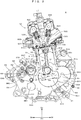
Fig. 2 is a partial cross-sectional view showing the internal configuration of an engine taken at a substantially central cross section. -
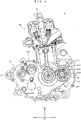
Fig. 3 is a partial cross-sectional view showing the internal configuration of the engine taken at a cross section external to the cross-section ofFig. 2 . -
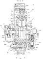
Fig. 4 is a partial cross-sectional view of the engine taken along a cutting line IV-IV shown inFig. 3 . -
Fig. 5 is a partial cross-sectional view showing a mechanism of transmitting a torque from a starter motor to a crankshaft. -
Fig. 6 is a partial cross-sectional view of the engine taken along a cutting line VI-VI shown inFig. 5 . -
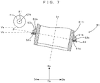
Fig. 7 schematically shows the layout of the starter motor. -
Fig. 1 is a side view showing a motorcycle corresponding to an example of a straddled vehicle equipped with an engine according to the present invention. Amotorcycle 1 shown inFig. 1 is so-called an off-road type vehicle. Meanwhile, in addition to this type, the straddled vehicle includes motorcycles of an on-road type, a scooter-type, a so-called moped-type, etc. The vehicle according to the present invention includes not only the straddled vehicle but also includes an all terrain vehicle (ATV), a four-wheel buggy, etc. - In this description, front, rear, left, and right means a front side, a rear side, a left side, and a right side respectively viewed from a passenger on a
seat 10. A front-rear direction Dp, a front side Df in the front-rear direction Dp, a rear side Db in the front-rear direction Dp, a vehicle-width direction Dw, and a vertical direction Dv are shown, where appropriate. Each of the front-rear direction Dp and the vehicle-width direction Dw is a horizontal direction. The front-rear direction Dp, the vehicle-width direction Dw, and the vertical direction Dv are orthogonal to each other. - The
motorcycle 1 includes avehicle body frame 2. Thevehicle body frame 2 has ahead pipe 21, amain frame 22, atank rail 23, a seat rail 24, aback stay 25, adown frame 26, etc. Thehead pipe 21 is arranged at an end portion of thevehicle body frame 2 on the front side Df. Themain frame 22 extends from thehead pipe 21 toward the rear side Db and is bent downward. Thetank rail 23 is arranged between thehead pipe 21 and thetank rail 23. Afuel tank 31 is attached to thetank rail 23. The seat rail 24 extends from themain frame 22 toward the rear side Db. Theseat 10 is attached to the seat rail 24. An end portion of the seat rail 24 on the rear side Db is connected to themain frame 22 with theback stay 25. Thedown frame 26 extends downward from thehead pipe 21 and is bent toward the rear side Db. Respective end portions of thedown frame 26 and themain frame 22 on the rear side Db are connected to each other. - A steering shaft not shown in the drawings is rotatably inserted into the
head pipe 21. The steering shaft has an upper end portion to which ahandle 32 is attached. Afront fork 33 extending diagonally downward toward the front side Df is attached to the steering shaft. Thefront fork 33 has a lower end portion to which afront wheel 34 is attached rotatably. - A
pivot shaft 221 is attached to an end portion of themain frame 22 on the rear side Db. Arear arm 35 extends from thepivot shaft 221 toward the rear side Db. While therear arm 35 is supported by thepivot shaft 221 so as to be pivotable upward and downward (vertical direction Dv) about thepivot shaft 221, therear arm 35 is attached to themain frame 22 via agear suspension 36. Arear wheel 37 is rotatably attached to an end portion of therear arm 35 on the rear side Db. - An
engine 5 is mounted to thevehicle body frame 2 in a region surrounded by themain frame 22 and thedown frame 26. Theengine 5 rotates therear wheel 37 via a secondary speed reducer not shown in the drawings. The secondary speed reducer can use any one of a chain-driven system, a shaft-driven system, and a belt-driven system. -
Fig. 2 is a partial cross-sectional view showing the internal configuration of an engine taken at a substantially central cross section.Fig. 3 is a partial cross-sectional view showing the internal configuration of the engine taken at a cross section external to the cross-section ofFig. 2 .Fig. 4 is a partial cross-sectional view of the engine taken along a cutting line IV-IV shown inFig. 3 . Theengine 5 includes acylinder block 51, acylinder head 52 attached to the upper end of thecylinder block 51, and acrankcase 53 attached to the lower end of thecylinder block 51. Thecylinder block 51 has ahead mating surface 51a as a surface of mating to thecylinder head 52. Thecylinder head 52 has acylinder mating surface 52a as a surface of mating to thecylinder block 51. With thehead mating surface 51a of thecylinder block 51 and thecylinder mating surface 52a of thecylinder head 52 in mating contact with each other, thecylinder block 51 and thecylinder head 52 are attached to each other. Thecylinder block 51 has an outer peripheral surface provided with aflange 51b. Theflange 51b has acrank mating surface 51c as a surface of mating to thecrankcase 53. Thecrankcase 53 has acylinder mating surface 53c as a surface of mating to thecylinder block 51. With thecrank mating surface 51c of thecylinder block 51 and thecylinder mating surface 53c of thecrankcase 53 in mating contact with each other, thecylinder block 51 and thecrankcase 53 are attached to each other. - The
engine 5 is a single-cylinder type engine with asingle cylinder 511 provided at thecylinder block 51. Apiston 512 is arranged in thecylinder 511. Thepiston 512 can make reciprocating motion in thecylinder 511. Thecylinder 511 is inclined rearward. More specifically, an axis Lc of thecylinder 511 is inclined toward the rear side Db with respect to the vertical direction Dv. In other words, the axis Lc of thecylinder 511 is inclined further toward the rear side Db at a higher position. The axis Lc of thecylinder 511 can be determined as a virtual line passing through the center of a bore in thecylinder 511 and extending parallel to the direction of the stroke of thepiston 512, for example. - The
cylinder head 52 includes anintake port 522 communicating with a combustion chamber defined between thecylinder head 52 and the upper end surface of thepiston 512, and anintake valve 523 for opening and closing theintake port 522 for the combustion chamber. Theintake valve 523 is biased by avalve spring 524 to be located at a position of closing theintake port 522. Rotating acamshaft 525 contacting with the upper end of theintake valve 523 allows opening and closing of theintake valve 523. Thecylinder head 52 includes anexhaust port 526 communicating with the combustion chamber, and anexhaust valve 527 for opening and closing theexhaust port 526 for the combustion chamber. Theexhaust valve 527 is biased by avalve spring 528 to be located at a position of closing theexhaust port 526. Rotating acamshaft 529 contacting with the upper end of theexhaust valve 527 allows opening and closing of theexhaust valve 527. In this way, theengine 5 has an intake and exhaust valve mechanism of a double over head camshaft (DOHC) type with thecamshafts engine 5 has a multivalve mechanism with multiple (two)intake valves 523 and multiple (two)exhaust valves 527. - The
crankcase 53 includes ahousing part 54 housing the mechanical structures of theengine 5, and a reservoir part 55 (oil tank) storing engine oil circulating in theengine 5. Thehousing part 54 and thereservoir part 55 are separated by apartition 56. Further, thehousing part 54 includes a crankchamber 541 inside. - The crank
chamber 541 communicates with thecylinder 511 and houses acrankshaft 61 arranged parallel to the vehicle-width direction Dw. Thecrankshaft 61 includes acrank journal 611 supported by thecrankcase 53 so as to be rotatable about a crank axis C61 parallel to the vehicle-width direction Dw, and a crankpin 612 eccentric with respect to the crank axis C61. Thecrank pin 612 is connected to thepiston 512 with a connectingrod 62. Thecrankshaft 61 rotates about a crank axis C61 in conjunction with the reciprocating motion of thepiston 512. Thecrankshaft 61 includes acounterweight 613 eccentric with respect to the crank axis C61 toward the opposite side of thecrank pin 612. Thecounterweight 613 contributes to reduction of vibration. - The crank
chamber 541 houses abalance shaft 63 arranged parallel to the vehicle-width direction Dw. Thebalance shaft 63 is supported by thecrankcase 53 so as to be rotatable about a balancer axis C63 parallel to the vehicle-width direction Dw, and includes aweight 631 eccentric with respect to the balancer axis C63. Thebalance shaft 63 rotates in conjunction with the rotation of thecrankshaft 61 to reduce vibration of thecrankshaft 61. - A
primary drive gear 614 is attached to thecrankshaft 61 to be coaxial with thecrankshaft 61. Theprimary drive gear 614 rotates together with thecrankshaft 61 about the crank axis C61. Further, abalancer gear 632 is attached to thebalance shaft 63 to be coaxial with thebalance shaft 63. Thebalance shaft 63 rotates together with thebalancer gear 632 about the balancer axis C63. Theprimary drive gear 614 and thebalancer gear 632 are engaged with each other, the reduced rotation of thecrankshaft 61 is transmitted to thebalance shaft 63. - The
engine 5 includes agenerator 64 that generates power from the rotary motion of thecrankshaft 61. Thegenerator 64 includes aflywheel 641 and astator coil 642 arranged inside theflywheel 641. Theflywheel 641 is attached to thecrankshaft 61 to be coaxial with thecrankshaft 61, and rotatable about the crank axis C61 together with thecrankshaft 61. Theflywheel 641 includes N-pole magnets and S-pole magnets aligned alternately to surround thestator coil 642 from outside. Thegenerator 64 generates power in response to electromagnetic induction generated between the magnets and thestator coil 642 by the rotation of theflywheel 641. - The crank
chamber 541 further houses aclutch mechanism 65 and atransmission 66. As shown inFig. 4 , an end portion of thecrankcase 53 in the vehicle-width direction Dw forms aclutch box 532 covering theclutch mechanism 65 and projects further than thecylinder 511 in the vehicle-width direction Dw. Theclutch mechanism 65 includes aclutch housing 651 rotatable about a main axis C67 parallel to the vehicle-width direction Dw. Theclutch housing 65 has an outer periphery provided with a primary drivengear 652 centered on a main axis C65. Theprimary drive gear 614 and the primary drivengear 652 are engaged with each other to form a primary speed reducer of reducing the rotation of thecrankshaft 61 and transmitting it to theclutch housing 651. - In the
clutch mechanism 65, aclutch boss 653 rotatable about the main axis C67 is arranged inside theclutch housing 651. Further,friction plates 654 to rotate together with theclutch housing 651 andclutch plates 655 to rotate together with theclutch boss 653 are aligned alternately. Theclutch mechanism 65 further includes apressure part 656 biased toward theclutch boss 653 by the elastic force of a clutch spring. Theclutch mechanism 65 presses thefriction plates 654 and theclutch plates 655 to theclutch boss 653 by thepressure part 656 to allow transmission of the rotation of theclutch housing 651 to theclutch boss 653. In another case, theclutch mechanism 65 moves pressurepart 656 toward the opposite side of theclutch boss 653 against the elastic force of the clutch spring to allow interruption of transmission of the rotation from theclutch housing 651 to theclutch boss 653. - A
main shaft 67 of thetransmission 66 is attached to theclutch boss 653. Thus, theclutch mechanism 65 can make transmitting motion of transmitting power from thecrankshaft 61 to themain shaft 67 and interrupting motion of interrupting transmission of the power from thecrankshaft 61 to themain shaft 67 selectively. - The
transmission 66 includes themain shaft 67 and adrive shaft 68 both arranged parallel to the vehicle-width direction Dw. Themain shaft 67 is supported by thecrankcase 53 so as to be rotatable about the main axis C67. Thedrive shaft 68 is supported by thecrankcase 53 so as to be rotatable about a drive axis C68 parallel to the vehicle-width direction Dw. Themain shaft 67 is provided with a plurality ofgears 671 forming a part of thetransmission 66. Thus, the weight of themain shaft 67 including the plurality ofgears 671 is generally larger than that of the foregoingbalance shaft 63. Themain shaft 67 is further provided with ashift fork 672 for causing thegears 671 to slide toward the axis direction of the main shaft 67 (vehicle-width direction Dw). Thedrive shaft 68 is provided with a plurality ofgears 681, and ashift fork 682 for causing thegears 681 to slide toward the axis direction of the drive shaft 68 (vehicle-width direction Dw). Ashift drum 661 to rotate in response to driver's operation is provided for theshift forks shift forks gear 671 and thegear 681 respectively located at their positions corresponding to the rotation angle of theshift drum 661. In this way, thetransmission 66 transmits the rotation of themain shaft 67 to thedrive shaft 68 at a transmission gear ratio responsive to the driver's operation. The rotation of thedrive shaft 68 is transmitted to therear wheel 37 by the secondary speed reducer. - As described above, the engine oil is cyclically supplied to the crank
chamber 54. The bottom of thecrank chamber 541 functions as anoil pan 544 to receive the engine oil dripping by its own weight. - The
reservoir part 55 stores the engine oil in areservoir chamber 551 inside thereservoir part 55. Thereservoir chamber 551 is arranged on the front side Df of thecrank chamber 541 and overlaps thecrank chamber 541 at least partially in a front view from the front side Df. The engine oil has a composition containing mineral-based oil, chemically synthesized oil, or partially chemically synthesized oil as base oil, and an adder added to the base oil. The engine oil is circulated in theengine 5 by a pump (scavenge pump or feed pump). This pump is driven by using the rotation of thecrankshaft 61. More specifically, a pump gear (not shown in the drawings) engaging with theprimary drive gear 614 is attached to the pump to be coaxial with the pump. Theprimary drive gear 614 and the pump gear transmit the rotation of thecrankshaft 61 to the pump. - The following describes layout in the
engine 5 in detail taken in a side view from the axis direction of the crankshaft 61 (namely, from the vehicle-width direction Dw) shown inFig. 2 . Thecrankshaft 61, thebalance shaft 63, themain shaft 67, and thedrive shaft 68 are arranged parallel to each other. As shown inFig. 2 , thecrankshaft 61 is offset rearward from the axis Lc of thecylinder 511. More specifically, a virtual half line Lh starting from the crank axis C61 of thecrankshaft 61 and extending parallel to the axis Lc of thecylinder 511 toward thecylinder 511 is located rearward of the axis Lc of thecylinder 511. From a different viewpoint, in an offset direction Do normal to each of the axis Lc of thecylinder 511 and the crank axis C61, the axis Lc of thecylinder 511 is located closer to thebalance shaft 63 than the virtual half line Lh. In this way, the crank axis C61 (or virtual half line Lh) is located on one side Do1 of the offset direction Do in respect with the axis Lc of thecylinder 511 , and thebalance shaft 63 is located on the other side Do2 of the offset direction Do in respect with the axis Lc of thecylinder 511. The other side Do2 is opposite to the one side Do1. - The
balance shaft 63 is arranged on the opposite side of themain shaft 67 across the virtual half line Lh. "Thebalance shaft 63 being arranged on the opposite side of themain shaft 67 across the virtual half line Lh" has the same meaning as thebalance shaft 63 being arranged on the opposite side of themain shaft 67 across a virtual line passing through the crank axis C61 and extending parallel to the axis Lc of thecylinder 511. An angle θ1 (0° < θ1 < 90°) is provided between the virtual half line Lh and a first virtual line segment L1 between the main axis C67 and the crank axis C61. Further, an angle θ2 (0° < θ2) is provided between the virtual half line Lh and a second virtual line segment L2 between the balancer axis C63 and the crank axis C61. Thecrankshaft 61, thebalance shaft 63, and themain shaft 67 are arranged so as to fulfill a relationship of angle θ1 < angle θ2. - With the
engine 5 mounted to thevehicle body frame 2, thetransmission 66 is located on the rear side Db in respect with thecrankshaft 61. An angle θ3 is provided between the virtual half line Lh and a third virtual line segment L3 between the drive axis C68 and the crank axis C61. Thecylinder 511 is tilted toward thetransmission 66 so as to make the angle θ3 less than 90° (0° < θ3 < 90°). In this case, the position of thedrive shaft 68 of thetransmission 66 is generally located near thepivot shaft 221. Thus, like the tilt toward thedrive shaft 68, thecylinder 511 becomes tilted toward thepivot shaft 221. - A line segment and a half line form a major angle (an angle greater than 180 degrees) and a minor angle (an angle less than 180 degrees), and an angle therebetween described herein means the minor angle. Specifically, all the angle θ1, the angle θ2, and the angle θ3 are smaller than 180 degrees. The axis Lc, the virtual half line Lh, the first virtual line segment L1, the second virtual line segment L2, and the third virtual line segment L3 mentioned herein are all normal to the axis direction of the crankshaft 61 (vehicle-width direction Dw).
- In the
engine 5 having the foregoing configuration, the respective masses of themain shaft 67 and thebalance shaft 63 are distributed to the opposite sides of the virtual half line Lh starting from the crank axis C61 and extending parallel to the axis Lc of thecylinder 511 toward thecylinder 511. Hence, the arrangement of themain shaft 67 influences mass centralization. In this regard, in this embodiment, themain shaft 67 is arranged so as to fulfill the relationship of angle θ1 < angle θ2. More specifically, to encourage mass centralization, themain shaft 67 is arranged close to the virtual half line Lh starting from the crank axis C61 so as to fulfill this angular relationship. By doing so, mass centralization can be encouraged in theengine 5 provided with themain shaft 67, thecrankshaft 61, and thebalance shaft 63. - Next, a starter motor for starting the
crankshaft 61 will be mainly described.Fig. 5 is a partial cross-sectional view showing a mechanism of transmitting a torque from a starter motor to a crankshaft.Fig. 6 is a partial cross-sectional view of the engine taken along a cutting line VI-VI shown inFig. 5 .Fig. 7 schematically shows the layout of the starter motor. - A
starter motor 71 is arranged on the front side Df of thecylinder 511 and overlaps thecylinder 511 at least partially in a front view from the front side Df. In this way, thestarter motor 71 is arranged on the opposite side of thetransmission 66 across thecylinder 511, and the axis Lc of thecylinder 511 passes through between thestarter motor 71 and thetransmission 66. As particularly shown inFig. 7 , thestarter motor 71 is above thecylinder mating surface 53c of thecrankcase 53 in the vertical direction Dv. In other words, a bottom Va of thestarter motor 71 is above a top Vb of thecylinder mating surface 53c of thecrankcase 53. The position of thestarter motor 71 is on the side of thecylinder head 52 with respect to a virtual plane P including thecylinder mating surface 53c of thecrankcase 53, in other words, on the opposite side of thecrankshaft 61 across the virtual plane P. Thestarter motor 71 is housed in amotor case 72 on the front side Df of thecylinder 511, in other words, on the opposite side of thetransmission 66 across thecylinder 511. Thestarter motor 71 and themotor case 72 are attachable and detachable together to and from thecrankcase 53. The rotational axis of the motor case 72 (motor rotational axis C71) is parallel to the crankshaft 61 (the crank axis C61 of the crankshaft 61). - The
engine 5 transmits the output (torque) of thestarter motor 71 to thecrankshaft 61 using amulti-speed reducer 8. Themulti-speed reducer 8 is configured using multiple (six) gears 81 to 86. More specifically, thedriving gear 81 is attached to the output shaft of thestarter motor 71 to be coaxial with the output shaft. Thedriving gear 81 rotates about the rotational axis (motor rotational axis C71) of thestarter motor 71 in response to the rotation of thestarter motor 71. The drivengear 82 having more teeth than the drivinggear 81 is attached to thecrankshaft 61 so as to be coaxial with thecrankshaft 61. The drivengear 82 rotates about the crank axis C61 together with thecrankshaft 61. - A
double gear 834 and adouble gear 856 are provided between the drivinggear 81 and the drivengear 82 on a transmission path of the output (driving force) of thestarter motor 71. Thedouble gear 834 includes theinput side gear 83 and theoutput side gear 84 having less teeth than theinput side gear 83. Theinput side gear 83 and theoutput side gear 84 are arranged coaxially. Theinput side gear 83 is engaged with thedriving gear 81. In response to input from thedriving gear 81, theinput side gear 83 and theoutput side gear 84 rotate integrally about a rotational axis C834. Thedouble gear 856 includes theinput side gear 85 and theoutput side gear 86 having less teeth than theinput side gear 85. Theinput side gear 85 and theoutput side gear 86 are arranged coaxially. Theinput side gear 85 is engaged with theoutput side gear 84 of thedouble gear 834. In response to input from thedouble gear 834, theinput side gear 85 and theoutput side gear 86 rotate integrally about a rotational axis C856. In this way, themulti-speed reducer 8 reduces the output of thestarter motor 71 at three stages and transmits the reduced output to thecrankshaft 61, thereby rotating thecrankshaft 61. - In the foregoing
engine 5, thecylinder 511 is tilted toward thetransmission 66 so that the angle θ3 between the virtual half line Lh and the third virtual line segment L3 is less than 90°. By tilting thecylinder 511 toward thetransmission 66 in this way, it becomes possible to ensure wide space on the opposite side of the transmission 66 (transmission opposite side) across thecylinder 511. Thestarter motor 71 is arranged on the transmission opposite side across thecylinder 511 and on the opposite side of thecrankshaft 61 across thecylinder mating surface 53c. In this way, the motor is arranged through effective use of the space on the transmission opposite side of thecylinder 511. Further, the output of thestarter motor 71 is reduced in speed by themultiple gears 81 to 86 and then transmitted to thecrankshaft 61. Thus, output required for thestarter motor 71 is small to allow size reduction of thestarter motor 71. As a result, it becomes possible to ensure space for the arrangement of thestarter motor 71 while the tilt of thecylinder 511 is suppressed. - In particular, in the
engine 5 described herein as an example, thecylinder 511 is arranged in such a manner that the axis Lc of thecylinder 511 is tilted further toward the rear side Db at a higher position. By tilting thecylinder 511 toward the rear side Db in this way, it becomes possible to ensure wide space on the front side Df of thecylinder 511. Thestarter motor 71 is arranged on the front side Df of thecylinder 511 and above thecylinder mating surface 53c. In this way, thestarter motor 71 is arranged through effective use of the space on the front side Df of thecylinder 511. Further, the output of thestarter motor 71 is reduced in speed by themultiple gears 81 to 86 and then transmitted to thecrankshaft 61. Thus, output required for thestarter motor 71 is small to allow size reduction of thestarter motor 71. As a result, it becomes possible to ensure space for the arrangement of thestarter motor 71 on the front side Df of thecylinder 511 while the tilt of thecylinder 511 toward the rear side Db is suppressed. In this way, while thestarter motor 71 is arranged on the front side Df of thecylinder 511, the tilt of thecylinder 511 toward the rear side Db can be suppressed. - The multiple gears 81 to 86 include the
driving gear 81 attached to the output shaft of thestarter motor 71, and the drivengear 82 attached to thecrankshaft 61. Further, thedouble gears gear 81 and the drivengear 82 on the transmission path of driving force reduce the output of thestarter motor 71 and transmit the reduced output to thecrankshaft 61. Such speed reduction at multiple states using thedouble gears starter motor 71 effectively. As a result, while the tilt of thecylinder 511 is suppressed, it becomes possible to ensure space for the arrangement of thestarter motor 71 more reliably. - As shown in
Fig. 5 , as viewed from the direction of the rotational axis of the starter motor 71 (from the vehicle-width direction Dw), the rotational axes C834 and C856 of thegears 83 to 86 are located on the side of the crank axis C61 in respect with the motor rotational axis C71 in a direction Dc parallel to thecylinder mating surface 53c. This configuration reduces bulge of theengine 5 to contribute to size reduction of theengine 5 more effectively. - As shown in
Fig. 5 , as viewed from the direction of the rotational axis of thestarter motor 71, respective far-side end portions of themultiple gears 81 to 86 from the axis Lc are located on the side of the axis Lc in respect with a far-side end portion of themotor case 72 from the axis Lc in the direction Dc parallel to thecylinder mating surface 53c. This configuration reduces bulge of theengine 5 to allow size reduction of theengine 5. The far-side end portion mentioned herein means one end portion of the opposite ends of a target object (gear, motor case) in the direction Dc and farther from the axis Lc. - As shown in
Fig. 5 , as viewed from the direction of the motor rotational axis of the starter motor 71 (motor rotational axis C71), gears other than the drivinggear 81 and the drivengear 82, specifically, thegears 83 to 86 have the rotational axes C834 and C856 that fulfill predetermined positional relationships with the motor rotational axis C71. More specifically, all the motor rotational axis C71 and the rotational axes C834 and C856 are on the same side relative to the axis Lc of the cylinder 511 (inFig. 5 , on the left side). An acute angle α1 is provided between the axis Lc and a virtual line I1 passing through the motor rotational axis C71 and crank axis C61, an acute angle α2 is provided between the axis Lc and a virtual line 12 passing through the rotational axis C834 of thegears virtual line 13 passing through the rotational axis C856 of thegears starter motor 71 is arranged in such a manner that the motor rotational axis C71 is located on the side of the virtual half line Lh of thecylinder 511 in respect with thevirtual lines 12 and 13 passing through the rotational axes C834 and C856 of thegears 83 to 86 respectively and the crank axis C61. This configuration reduces bulge of theengine 5 to contribute to size reduction of theengine 5 more effectively. - As described above, in the foregoing embodiment, the
engine 5 corresponds to an example of an "engine" of the present invention. Thecylinder 511 corresponds to an example of a "cylinder" of the present invention. The axis Lc corresponds to an example of the "axis of the cylinder" of the present invention. The virtual half line Lh corresponds to an example of a "virtual half line" of the present invention. The third virtual line segment L3 corresponds to an example of a "virtual line segment" of the present invention. Thecrankcase 53 corresponds to an example of a "crankcase" of the present invention. Thecylinder mating surface 53c corresponds to an example of a "cylinder mating surface" of the present invention. Thecrankshaft 61 corresponds to an example of a "crankshaft" of the present invention. Thetransmission 66 corresponds to an example of a "transmission" of the present invention. Thedrive shaft 68 corresponds to an example of a "drive shaft" of the present invention. Thestarter motor 71 corresponds to an example of a "motor" of the present invention. Themotor case 72 corresponds to an example of a "motor case" of the present invention. The multiple gears 81 to 86 correspond to examples of "multiple gears" of the present invention. Thedriving gear 81 corresponds to an example of a "driving gear" of the present invention. The drivengear 82 corresponds to an example of a "driven gear" of the present invention. Theinput side gear 83 and theinput side gear 85 each correspond to an example of an "input side gear" of the present invention. Theoutput side gear 84 and theoutput side gear 86 each correspond to an example of an "output side gear" of the present invention. Thedouble gear 834 and thedouble gear 856 each correspond to an example of a "double gear" of the present invention. Themotorcycle 1 corresponds to an example of a "vehicle" of the present invention. Thefront wheel 34 and therear wheel 37 correspond to examples of a "wheel" of the present invention. - The present invention is not limited to the foregoing embodiment. Various changes other than those described above are applicable within a range not deviating from the substance of the invention. Regarding the number of the
multiple gears 81 to 86 making up themulti-speed reducer 8, for example, this number can be changed, if appropriate, as long as it is two or more. - The arrangement of the
multiple gears 81 to 86 making up themulti-speed reducer 8 can also be changed, if appropriate. Thus, the respective far-side end portions of themultiple gears 81 to 86 from the axis Lc are not required to be closer to the axis Lc than the far-side end portion of themotor case 72 from the axis Lc. A far-side end portion of any of the gears from the axis Lc may be located at an opposite side of the axis Lc across the far-side end portion of themotor case 72 from the axis Lc. - Both the rotational axes C834 and C856 of the
gears 83 to 86 are not always required to be located closer to thecrankshaft 61 than the motor rotational axis C71 in the direction Dc. For example, only the rotational axis of one of thegears 83 to 86 may be located closer to thecrankshaft 61 than the motor rotational axis C71, and the rotational axes of the other gears may be located at an opposite side of thecrankshaft 61 across the motor rotational axis C71. In this case, the rotational axis of at least one of thegears 83 to 86 may be configured to be located closer to thecrankshaft 61 than the motor rotational axis C71 in the direction Dc. This configuration reduces bulge of theengine 5 to contribute to size reduction of theengine 5. - For example, in the foregoing description, the
engine 5 described as an example is a single-cylinder type engine with thesingle cylinder 511 provided at thecylinder block 51. Alternatively, the number of thecylinders 511 of theengine 5 is not limited to one but theengine 5 may include two ormore cylinders 511. - The intake and exhaust valve mechanism provided at the
engine 5 is not limited to a mechanism of the foregoing DOHC type but it may also be a mechanism of a different type such as a single over head camshaft (SOHC). Further, a system for driving theintake valve 523 and theexhaust valve 527 is not limited to the foregoing direct-drive system but it may also be a different system such as a rocker arm system. - The specific configuration of the
crankcase 53 can be changed, if appropriate. Thus, thecrankcase 53 is not always required to include thereservoir part 55 integrally, for example. - The position or angle for attaching the
engine 5 to thevehicle body frame 2 is not limited to that described in the foregoing example but can be changed, if appropriate. - The present invention is applicable to every type of engine provided with a motor that starts the rotation of a crankshaft, and to every type of vehicle comprising the engine.
-
- 1...
- motorcycle (vehicle)
- 34...
- front wheel (wheel)
- 37...
- rear wheel (wheel)
- 5...
- engine
- 511...
- cylinder
- 53...
- crankcase
- 53c...
- cylinder mating surface
- 61...
- crankshaft
- 66...
- transmission
- 68...
- drive shaft
- 71...
- starter motor (motor)
- 72...
- motor case
- 81-86...
- multiple gear
- 81...
- driving gear
- 82...
- driven gear
- 83...
- input side gear
- 84...
- output side gear
- 85...
- input side gear
- 86...
- output side gear
- 834...
- double gear
- 856...
- double gear
- Lc...
- axis (axis of cylinder)
- Lh...
- virtual half line
- L3...
- third virtual line segment (virtual line segment)
Claims (7)
- An engine comprising:a cylinder;a crankcase in mating contact with the cylinder at a cylinder mating surface and attached to the cylinder;a crankshaft rotatable about a crank axis, at least a part of the crankshaft being arranged in the crankcase;a transmission that outputs the rotation of the crankshaft from a drive shaft rotatable about a drive axis, at least a part of the transmission being arranged in the crankcase;a motor; andmultiple gears that reduce an output of the motor and transmit a reduced outputs to the crankshaft, whereinthe cylinder is tilted toward the transmission so that an angle between a virtual half line and a virtual line segment is less than 90°, the virtual half line extending parallel to an axis of the cylinder toward the cylinder from the crank axis, the virtual line segment extending between the crank axis and the drive axis, andthe motor is arranged on the opposite side of the transmission across the cylinder and on the opposite side of the crankshaft across the cylinder mating surface, with a rotational axis of the motor being parallel to the crankshaft.
- The engine according to claim 1, wherein
the multiple gears include a driving gear attached to an output shaft of the motor, a driven gear attached to the crankshaft, and a double gear located between the driving gear and the driven gear on a transmission path of driving force, the double gear including an input side gear and an output side gear arranged coaxially, the input side gear receiving the driving force from the driving gear, the output side gear outputting the driving force to the driven gear, and
the multiple gears reduce the output of the motor and transmit the reduced output to the crankshaft. - The engine according to claim 2, wherein
as viewed from a direction of the rotational axis of the motor, at least one of the multiple gears other than the driving gear and the driven gear has a rotational axis located closer to the crankshaft than the rotational axis of the motor in a direction parallel to the cylinder mating surface. - The engine according to claim 2, wherein
as viewed from a direction of the rotational axis of the motor, each gear of the multiple gears other than the driving gear and the driven gear has a rotational axis located closer to the crankshaft than the rotational axis of the motor in a direction parallel to the cylinder mating surface. - The engine according to any one of claims 1 to 4, further comprising a motor case housing the motor, wherein
as viewed from a direction of the rotational axis of the motor, respective far-side end portions of the multiple gears from an axis of the cylinder are located closer to the axis of the cylinder than a far-side end portion of the motor case from the axis of the cylinder in a direction parallel to the cylinder mating surface. - The engine according to any one of claims 1 to 5, wherein
as viewed from a direction of the rotational axis of the motor, the rotational axis of the motor is located closer to an axis of the cylinder than a line passing through the rotational axis of a gear other than the driving gear and the driven gear and the crank axis. - A vehicle comprising:the engine according to any one of claims 1 to 6; anda wheel to be driven by the engine.
Applications Claiming Priority (2)
| Application Number | Priority Date | Filing Date | Title |
|---|---|---|---|
| JP2017150855 | 2017-08-03 | ||
| PCT/JP2018/028980 WO2019026988A1 (en) | 2017-08-03 | 2018-08-02 | Engine and vehicle |
Publications (3)
| Publication Number | Publication Date |
|---|---|
| EP3663559A1 true EP3663559A1 (en) | 2020-06-10 |
| EP3663559A4 EP3663559A4 (en) | 2020-08-26 |
| EP3663559B1 EP3663559B1 (en) | 2022-11-16 |
Family
ID=65232913
Family Applications (1)
| Application Number | Title | Priority Date | Filing Date |
|---|---|---|---|
| EP18841581.4A Active EP3663559B1 (en) | 2017-08-03 | 2018-08-02 | Engine and vehicle |
Country Status (2)
| Country | Link |
|---|---|
| EP (1) | EP3663559B1 (en) |
| WO (1) | WO2019026988A1 (en) |
Family Cites Families (10)
| Publication number | Priority date | Publication date | Assignee | Title |
|---|---|---|---|---|
| JPS53149109A (en) | 1977-06-01 | 1978-12-26 | Toyota Motor Corp | Slag removing agnet |
| JPS61187533A (en) * | 1985-02-14 | 1986-08-21 | Yamaha Motor Co Ltd | Engine structure of motorcycle |
| JP3743239B2 (en) * | 1999-12-20 | 2006-02-08 | スズキ株式会社 | Scooter type motorcycle |
| DE10006690C1 (en) * | 2000-02-15 | 2001-06-28 | Ktm Sportmotorcycle Ag Mattigh | Starter for motorcycle two-cylinder V-configuration internal combustion engine has starter motor and gearbox mounted in V-shaped intermediate space between cylinders above crankshaft |
| JP3986760B2 (en) * | 2001-02-02 | 2007-10-03 | 本田技研工業株式会社 | Motorcycle engine |
| JP3616602B2 (en) * | 2002-02-19 | 2005-02-02 | 川崎重工業株式会社 | Motorcycle drive device |
| JP4373195B2 (en) * | 2003-11-21 | 2009-11-25 | ヤマハ発動機株式会社 | Engine balancer equipment |
| JP2006316679A (en) * | 2005-05-11 | 2006-11-24 | Yamaha Motor Co Ltd | Engine device for motorcycle |
| JP5339602B2 (en) * | 2009-03-30 | 2013-11-13 | 本田技研工業株式会社 | Motorcycle |
| JP6197370B2 (en) * | 2013-05-24 | 2017-09-20 | スズキ株式会社 | Motorcycle engine |
-
2018
- 2018-08-02 WO PCT/JP2018/028980 patent/WO2019026988A1/en unknown
- 2018-08-02 EP EP18841581.4A patent/EP3663559B1/en active Active
Also Published As
| Publication number | Publication date |
|---|---|
| EP3663559B1 (en) | 2022-11-16 |
| WO2019026988A1 (en) | 2019-02-07 |
| EP3663559A4 (en) | 2020-08-26 |
Similar Documents
| Publication | Publication Date | Title |
|---|---|---|
| AU2009230651B2 (en) | Engine balancer device | |
| JP6601147B2 (en) | Engine balancer device and motorcycle | |
| EP3663559B1 (en) | Engine and vehicle | |
| JPH1018855A (en) | Vehicular engine equipped with balancer | |
| EP1221560B1 (en) | Engine for a vehicle | |
| EP3663558B1 (en) | Engine and vehicle | |
| JP4369185B2 (en) | Parallel multi-cylinder engine | |
| EP3663547B1 (en) | Engine and vehicle | |
| US6964253B2 (en) | Balancer apparatus of engine | |
| JP5385664B2 (en) | Equipment arrangement structure in the crankcase | |
| JP4878853B2 (en) | Internal combustion engine | |
| JP2006170236A (en) | Shift drum driving mechanism for vehicle | |
| JP4303189B2 (en) | Variable stroke characteristics engine | |
| US8474430B2 (en) | Crankshaft mechanism for engine | |
| EP2372128B1 (en) | Crankcase of internal combustion engine | |
| JP6569468B2 (en) | Engine balancer device and motorcycle | |
| JP4927764B2 (en) | Shaft arrangement structure of internal combustion engine | |
| JP6569467B2 (en) | Engine balancer device and motorcycle | |
| JPS597735A (en) | V-type engine | |
| JP2011179483A (en) | Multi-cylinder engine | |
| JPH0362891B2 (en) |
Legal Events
| Date | Code | Title | Description |
|---|---|---|---|
| STAA | Information on the status of an ep patent application or granted ep patent |
Free format text: STATUS: THE INTERNATIONAL PUBLICATION HAS BEEN MADE |
|
| PUAI | Public reference made under article 153(3) epc to a published international application that has entered the european phase |
Free format text: ORIGINAL CODE: 0009012 |
|
| STAA | Information on the status of an ep patent application or granted ep patent |
Free format text: STATUS: REQUEST FOR EXAMINATION WAS MADE |
|
| 17P | Request for examination filed |
Effective date: 20200303 |
|
| AK | Designated contracting states |
Kind code of ref document: A1 Designated state(s): AL AT BE BG CH CY CZ DE DK EE ES FI FR GB GR HR HU IE IS IT LI LT LU LV MC MK MT NL NO PL PT RO RS SE SI SK SM TR |
|
| AX | Request for extension of the european patent |
Extension state: BA ME |
|
| A4 | Supplementary search report drawn up and despatched |
Effective date: 20200727 |
|
| RIC1 | Information provided on ipc code assigned before grant |
Ipc: F02B 67/00 20060101AFI20200721BHEP Ipc: F02N 11/00 20060101ALI20200721BHEP Ipc: F02N 15/02 20060101ALI20200721BHEP Ipc: B62M 7/02 20060101ALI20200721BHEP |
|
| DAV | Request for validation of the european patent (deleted) | ||
| DAX | Request for extension of the european patent (deleted) | ||
| STAA | Information on the status of an ep patent application or granted ep patent |
Free format text: STATUS: EXAMINATION IS IN PROGRESS |
|
| 17Q | First examination report despatched |
Effective date: 20210617 |
|
| REG | Reference to a national code |
Ref country code: DE Ref legal event code: R079 Ref document number: 602018043207 Country of ref document: DE Free format text: PREVIOUS MAIN CLASS: F02B0067000000 Ipc: B62M0023020000 |
|
| GRAP | Despatch of communication of intention to grant a patent |
Free format text: ORIGINAL CODE: EPIDOSNIGR1 |
|
| STAA | Information on the status of an ep patent application or granted ep patent |
Free format text: STATUS: GRANT OF PATENT IS INTENDED |
|
| RIC1 | Information provided on ipc code assigned before grant |
Ipc: F02N 11/00 20060101ALI20220628BHEP Ipc: B62M 7/02 20060101ALI20220628BHEP Ipc: F16F 15/26 20060101ALI20220628BHEP Ipc: F02N 15/04 20060101ALI20220628BHEP Ipc: F02N 15/00 20060101ALI20220628BHEP Ipc: F02B 61/06 20060101ALI20220628BHEP Ipc: F02B 61/02 20060101ALI20220628BHEP Ipc: B62M 23/02 20100101AFI20220628BHEP |
|
| INTG | Intention to grant announced |
Effective date: 20220729 |
|
| GRAS | Grant fee paid |
Free format text: ORIGINAL CODE: EPIDOSNIGR3 |
|
| GRAA | (expected) grant |
Free format text: ORIGINAL CODE: 0009210 |
|
| STAA | Information on the status of an ep patent application or granted ep patent |
Free format text: STATUS: THE PATENT HAS BEEN GRANTED |
|
| AK | Designated contracting states |
Kind code of ref document: B1 Designated state(s): AL AT BE BG CH CY CZ DE DK EE ES FI FR GB GR HR HU IE IS IT LI LT LU LV MC MK MT NL NO PL PT RO RS SE SI SK SM TR |
|
| REG | Reference to a national code |
Ref country code: GB Ref legal event code: FG4D |
|
| REG | Reference to a national code |
Ref country code: CH Ref legal event code: EP |
|
| REG | Reference to a national code |
Ref country code: IE Ref legal event code: FG4D |
|
| REG | Reference to a national code |
Ref country code: DE Ref legal event code: R096 Ref document number: 602018043207 Country of ref document: DE |
|
| REG | Reference to a national code |
Ref country code: AT Ref legal event code: REF Ref document number: 1531631 Country of ref document: AT Kind code of ref document: T Effective date: 20221215 |
|
| REG | Reference to a national code |
Ref country code: LT Ref legal event code: MG9D |
|
| REG | Reference to a national code |
Ref country code: NL Ref legal event code: MP Effective date: 20221116 |
|
| REG | Reference to a national code |
Ref country code: AT Ref legal event code: MK05 Ref document number: 1531631 Country of ref document: AT Kind code of ref document: T Effective date: 20221116 |
|
| PG25 | Lapsed in a contracting state [announced via postgrant information from national office to epo] |
Ref country code: SE Free format text: LAPSE BECAUSE OF FAILURE TO SUBMIT A TRANSLATION OF THE DESCRIPTION OR TO PAY THE FEE WITHIN THE PRESCRIBED TIME-LIMIT Effective date: 20221116 Ref country code: PT Free format text: LAPSE BECAUSE OF FAILURE TO SUBMIT A TRANSLATION OF THE DESCRIPTION OR TO PAY THE FEE WITHIN THE PRESCRIBED TIME-LIMIT Effective date: 20230316 Ref country code: NO Free format text: LAPSE BECAUSE OF FAILURE TO SUBMIT A TRANSLATION OF THE DESCRIPTION OR TO PAY THE FEE WITHIN THE PRESCRIBED TIME-LIMIT Effective date: 20230216 Ref country code: LT Free format text: LAPSE BECAUSE OF FAILURE TO SUBMIT A TRANSLATION OF THE DESCRIPTION OR TO PAY THE FEE WITHIN THE PRESCRIBED TIME-LIMIT Effective date: 20221116 Ref country code: FI Free format text: LAPSE BECAUSE OF FAILURE TO SUBMIT A TRANSLATION OF THE DESCRIPTION OR TO PAY THE FEE WITHIN THE PRESCRIBED TIME-LIMIT Effective date: 20221116 Ref country code: ES Free format text: LAPSE BECAUSE OF FAILURE TO SUBMIT A TRANSLATION OF THE DESCRIPTION OR TO PAY THE FEE WITHIN THE PRESCRIBED TIME-LIMIT Effective date: 20221116 Ref country code: AT Free format text: LAPSE BECAUSE OF FAILURE TO SUBMIT A TRANSLATION OF THE DESCRIPTION OR TO PAY THE FEE WITHIN THE PRESCRIBED TIME-LIMIT Effective date: 20221116 |
|
| PG25 | Lapsed in a contracting state [announced via postgrant information from national office to epo] |
Ref country code: RS Free format text: LAPSE BECAUSE OF FAILURE TO SUBMIT A TRANSLATION OF THE DESCRIPTION OR TO PAY THE FEE WITHIN THE PRESCRIBED TIME-LIMIT Effective date: 20221116 Ref country code: PL Free format text: LAPSE BECAUSE OF FAILURE TO SUBMIT A TRANSLATION OF THE DESCRIPTION OR TO PAY THE FEE WITHIN THE PRESCRIBED TIME-LIMIT Effective date: 20221116 Ref country code: LV Free format text: LAPSE BECAUSE OF FAILURE TO SUBMIT A TRANSLATION OF THE DESCRIPTION OR TO PAY THE FEE WITHIN THE PRESCRIBED TIME-LIMIT Effective date: 20221116 Ref country code: IS Free format text: LAPSE BECAUSE OF FAILURE TO SUBMIT A TRANSLATION OF THE DESCRIPTION OR TO PAY THE FEE WITHIN THE PRESCRIBED TIME-LIMIT Effective date: 20230316 Ref country code: HR Free format text: LAPSE BECAUSE OF FAILURE TO SUBMIT A TRANSLATION OF THE DESCRIPTION OR TO PAY THE FEE WITHIN THE PRESCRIBED TIME-LIMIT Effective date: 20221116 Ref country code: GR Free format text: LAPSE BECAUSE OF FAILURE TO SUBMIT A TRANSLATION OF THE DESCRIPTION OR TO PAY THE FEE WITHIN THE PRESCRIBED TIME-LIMIT Effective date: 20230217 |
|
| PG25 | Lapsed in a contracting state [announced via postgrant information from national office to epo] |
Ref country code: NL Free format text: LAPSE BECAUSE OF FAILURE TO SUBMIT A TRANSLATION OF THE DESCRIPTION OR TO PAY THE FEE WITHIN THE PRESCRIBED TIME-LIMIT Effective date: 20221116 |
|
| P01 | Opt-out of the competence of the unified patent court (upc) registered |
Effective date: 20230527 |
|
| PG25 | Lapsed in a contracting state [announced via postgrant information from national office to epo] |
Ref country code: SM Free format text: LAPSE BECAUSE OF FAILURE TO SUBMIT A TRANSLATION OF THE DESCRIPTION OR TO PAY THE FEE WITHIN THE PRESCRIBED TIME-LIMIT Effective date: 20221116 Ref country code: RO Free format text: LAPSE BECAUSE OF FAILURE TO SUBMIT A TRANSLATION OF THE DESCRIPTION OR TO PAY THE FEE WITHIN THE PRESCRIBED TIME-LIMIT Effective date: 20221116 Ref country code: EE Free format text: LAPSE BECAUSE OF FAILURE TO SUBMIT A TRANSLATION OF THE DESCRIPTION OR TO PAY THE FEE WITHIN THE PRESCRIBED TIME-LIMIT Effective date: 20221116 Ref country code: DK Free format text: LAPSE BECAUSE OF FAILURE TO SUBMIT A TRANSLATION OF THE DESCRIPTION OR TO PAY THE FEE WITHIN THE PRESCRIBED TIME-LIMIT Effective date: 20221116 Ref country code: CZ Free format text: LAPSE BECAUSE OF FAILURE TO SUBMIT A TRANSLATION OF THE DESCRIPTION OR TO PAY THE FEE WITHIN THE PRESCRIBED TIME-LIMIT Effective date: 20221116 |
|
| REG | Reference to a national code |
Ref country code: DE Ref legal event code: R097 Ref document number: 602018043207 Country of ref document: DE |
|
| PG25 | Lapsed in a contracting state [announced via postgrant information from national office to epo] |
Ref country code: SK Free format text: LAPSE BECAUSE OF FAILURE TO SUBMIT A TRANSLATION OF THE DESCRIPTION OR TO PAY THE FEE WITHIN THE PRESCRIBED TIME-LIMIT Effective date: 20221116 Ref country code: AL Free format text: LAPSE BECAUSE OF FAILURE TO SUBMIT A TRANSLATION OF THE DESCRIPTION OR TO PAY THE FEE WITHIN THE PRESCRIBED TIME-LIMIT Effective date: 20221116 |
|
| PLBE | No opposition filed within time limit |
Free format text: ORIGINAL CODE: 0009261 |
|
| STAA | Information on the status of an ep patent application or granted ep patent |
Free format text: STATUS: NO OPPOSITION FILED WITHIN TIME LIMIT |
|
| 26N | No opposition filed |
Effective date: 20230817 |
|
| PGFP | Annual fee paid to national office [announced via postgrant information from national office to epo] |
Ref country code: IT Payment date: 20230825 Year of fee payment: 6 |
|
| PG25 | Lapsed in a contracting state [announced via postgrant information from national office to epo] |
Ref country code: SI Free format text: LAPSE BECAUSE OF FAILURE TO SUBMIT A TRANSLATION OF THE DESCRIPTION OR TO PAY THE FEE WITHIN THE PRESCRIBED TIME-LIMIT Effective date: 20221116 |
|
| PGFP | Annual fee paid to national office [announced via postgrant information from national office to epo] |
Ref country code: FR Payment date: 20230828 Year of fee payment: 6 Ref country code: DE Payment date: 20230821 Year of fee payment: 6 |
|
| PG25 | Lapsed in a contracting state [announced via postgrant information from national office to epo] |
Ref country code: MC Free format text: LAPSE BECAUSE OF FAILURE TO SUBMIT A TRANSLATION OF THE DESCRIPTION OR TO PAY THE FEE WITHIN THE PRESCRIBED TIME-LIMIT Effective date: 20221116 |
|
| REG | Reference to a national code |
Ref country code: CH Ref legal event code: PL |
|
| PG25 | Lapsed in a contracting state [announced via postgrant information from national office to epo] |
Ref country code: MC Free format text: LAPSE BECAUSE OF FAILURE TO SUBMIT A TRANSLATION OF THE DESCRIPTION OR TO PAY THE FEE WITHIN THE PRESCRIBED TIME-LIMIT Effective date: 20221116 |
|
| PG25 | Lapsed in a contracting state [announced via postgrant information from national office to epo] |
Ref country code: LU Free format text: LAPSE BECAUSE OF NON-PAYMENT OF DUE FEES Effective date: 20230802 |
|
| GBPC | Gb: european patent ceased through non-payment of renewal fee |
Effective date: 20230802 |
|
| PG25 | Lapsed in a contracting state [announced via postgrant information from national office to epo] |
Ref country code: LU Free format text: LAPSE BECAUSE OF NON-PAYMENT OF DUE FEES Effective date: 20230802 Ref country code: CH Free format text: LAPSE BECAUSE OF NON-PAYMENT OF DUE FEES Effective date: 20230831 |