EP3663484A1 - Transmitter, system, formwork element, method for transmitting data and method for predicting stress on a formwork element - Google Patents
Transmitter, system, formwork element, method for transmitting data and method for predicting stress on a formwork element Download PDFInfo
- Publication number
- EP3663484A1 EP3663484A1 EP18210078.4A EP18210078A EP3663484A1 EP 3663484 A1 EP3663484 A1 EP 3663484A1 EP 18210078 A EP18210078 A EP 18210078A EP 3663484 A1 EP3663484 A1 EP 3663484A1
- Authority
- EP
- European Patent Office
- Prior art keywords
- formwork element
- formwork
- data
- form face
- sensor unit
- Prior art date
- Legal status (The legal status is an assumption and is not a legal conclusion. Google has not performed a legal analysis and makes no representation as to the accuracy of the status listed.)
- Granted
Links
Images




Classifications
-
- G—PHYSICS
- G01—MEASURING; TESTING
- G01M—TESTING STATIC OR DYNAMIC BALANCE OF MACHINES OR STRUCTURES; TESTING OF STRUCTURES OR APPARATUS, NOT OTHERWISE PROVIDED FOR
- G01M5/00—Investigating the elasticity of structures, e.g. deflection of bridges or air-craft wings
- G01M5/0041—Investigating the elasticity of structures, e.g. deflection of bridges or air-craft wings by determining deflection or stress
-
- E—FIXED CONSTRUCTIONS
- E04—BUILDING
- E04G—SCAFFOLDING; FORMS; SHUTTERING; BUILDING IMPLEMENTS OR AIDS, OR THEIR USE; HANDLING BUILDING MATERIALS ON THE SITE; REPAIRING, BREAKING-UP OR OTHER WORK ON EXISTING BUILDINGS
- E04G11/00—Forms, shutterings, or falsework for making walls, floors, ceilings, or roofs
- E04G11/06—Forms, shutterings, or falsework for making walls, floors, ceilings, or roofs for walls, e.g. curved end panels for wall shutterings; filler elements for wall shutterings; shutterings for vertical ducts
- E04G11/08—Forms, which are completely dismantled after setting of the concrete and re-built for next pouring
-
- E—FIXED CONSTRUCTIONS
- E04—BUILDING
- E04G—SCAFFOLDING; FORMS; SHUTTERING; BUILDING IMPLEMENTS OR AIDS, OR THEIR USE; HANDLING BUILDING MATERIALS ON THE SITE; REPAIRING, BREAKING-UP OR OTHER WORK ON EXISTING BUILDINGS
- E04G17/00—Connecting or other auxiliary members for forms, falsework structures, or shutterings
- E04G17/06—Tying means; Spacers ; Devices for extracting or inserting wall ties
-
- G—PHYSICS
- G01—MEASURING; TESTING
- G01L—MEASURING FORCE, STRESS, TORQUE, WORK, MECHANICAL POWER, MECHANICAL EFFICIENCY, OR FLUID PRESSURE
- G01L19/00—Details of, or accessories for, apparatus for measuring steady or quasi-steady pressure of a fluent medium insofar as such details or accessories are not special to particular types of pressure gauges
- G01L19/0007—Fluidic connecting means
- G01L19/0046—Fluidic connecting means using isolation membranes
-
- G—PHYSICS
- G01—MEASURING; TESTING
- G01M—TESTING STATIC OR DYNAMIC BALANCE OF MACHINES OR STRUCTURES; TESTING OF STRUCTURES OR APPARATUS, NOT OTHERWISE PROVIDED FOR
- G01M5/00—Investigating the elasticity of structures, e.g. deflection of bridges or air-craft wings
- G01M5/0083—Investigating the elasticity of structures, e.g. deflection of bridges or air-craft wings by measuring variation of impedance, e.g. resistance, capacitance, induction
-
- E—FIXED CONSTRUCTIONS
- E04—BUILDING
- E04G—SCAFFOLDING; FORMS; SHUTTERING; BUILDING IMPLEMENTS OR AIDS, OR THEIR USE; HANDLING BUILDING MATERIALS ON THE SITE; REPAIRING, BREAKING-UP OR OTHER WORK ON EXISTING BUILDINGS
- E04G9/00—Forming or shuttering elements for general use
- E04G9/02—Forming boards or similar elements
- E04G2009/028—Forming boards or similar elements with reinforcing ribs on the underside
Definitions
- the present invention relates to a transmitter for predicting stress on a formwork element. Furthermore, the present invention relates to a system for predicting stress on a formwork element. In addition, the present invention relates to a formwork element for use in a formwork.
- the present invention relates to a method for transmitting data for predicting stress on a formwork element.
- the present invention relates to a method for predicting stress on a formwork element.
- an important aspect is to monitor stress on said formwork elements that is induced into the formwork elements by the building material.
- An uneven load distribution within the formwork structure could also lead to local failures or an unwanted redistribution of loads.
- One or more tie rods taking up more load than expected can lead to instant tie rod failure.
- KR 20090016780 discloses a mold deformation detecting apparatus which is configured to detect deformation of a mold which supports a load when concrete is put into the mold and warn of danger so as to prevent safety accidents.
- a mold deformation detecting apparatus includes a detector and a controller. The detector detects a motion of a mold. The controller receives a signal from the detector and checks whether the mold is deformed. The frontend of the detector has a sensing bar in close proximity to the mold. The apparatus detects mold deformation according to whether the sensing bar is rotated.
- KR 20130070874 discloses a mold collapse sign detecting device comprising a clamp, a sensor, an A/D converter, a microcontroller, and a warning unit.
- the state in which the clamp is interlocked to a mold frame is detected by the sensor.
- Detected data is outputted from the sensor in a predetermined time after detecting the interlocking of the clamp and is memorized as a standard value.
- Change value applied to the mold frame is calculated by periodically comparing the detected data and the standard value. When the change value exceeds a critical value, a warning signal is outputted.
- the present invention relates to a transmitter for predicting stress on a formwork element during and/or after pouring a building material, in particular concrete, into a space enclosed by a formwork in accordance with claim 1, to a system for predicting stress on a formwork element during and/or after pouring a building material, in particular concrete, into a space enclosed by the framework in accordance with claim 2, to a formwork element for use in a formwork in accordance with claim 7, to a method for transmitting data for predicting stress on a formwork element during and/or after pouring a building material, in particular concrete, into a space enclosed by the formwork in accordance with claim 15 and to a method for predicting stress on a formwork element in accordance with claim 16.
- An aspect of the present invention relates to a transmitter for predicting stress on a formwork element during and/or after pouring a building material, in particular concrete, into a space enclosed by a formwork including the formwork element, the formwork element comprising a form face and a support structure which is attached to the form face and supporting the form face, wherein the form face is separated from or integrated into the support structure.
- the transmitter comprises the formwork element and data acquisition means comprising at least one sensor unit configured to acquire data in relation to the stress exerted on the formwork element by the building material, a control unit configured to control the at least one sensor unit and/or to process the acquired data, and a transmission unit configured to transmit the acquired data to a device located outside the formwork element, wherein the control unit and the transmission unit are arranged within the support structure, and wherein the at least one sensor unit is arranged at least partially within the support structure.
- a further aspect of the present invention relates to a system for predicting stress on a formwork element during and/or after pouring a building material, in particular concrete, into a space enclosed by a formwork including the formwork element, comprising the transmitter and the device configured to receive the acquired data.
- a further aspect of the present invention relates to a formwork element for use in a formwork, comprising a form face and a support structure which is attached to the form face and supporting the form face, wherein the form face is separated from or integrated into the support structure, the formwork element comprising data acquisition means comprising at least one sensor unit configured to acquire data in relation to the stress exerted on the formwork element by the building material, a control unit configured to control the at least one sensor unit and/or to process the acquired data, and a transmission unit configured to transmit the acquired data to a device located outside the formwork element, wherein the control unit and the transmission unit are arranged within the support structure, and wherein the at least one sensor unit is arranged at least partially within the support structure.
- a further aspect of the present invention relates to a method for transmitting data for predicting stress on a formwork element during and/or after pouring a building material, in particular concrete, into a space enclosed by a formwork including the formwork element, the formwork element comprising a form face and a support structure which is attached to the form face and supporting the form face.
- the form face is separated from or integrated into the support structure, the method comprising the steps of acquiring data in relation to the stress exerted on the formwork element by the building material by means of at least one sensor unit of a data acquisition means, controlling the at least one sensor unit by means of a control unit and/or processing the acquired data, wherein the control unit and the transmission unit are arranged within the support structure.
- the at least one sensor unit is arranged at least partially within the support structure, and transmitting the acquired data to a device located outside the formwork element by a transmission unit.
- a further aspect of the present invention relates to a method for predicting stress on a formwork element during and/or after pouring a building material, in particular concrete, into a space enclosed by a formwork including the formwork element, the method comprising the method for transmitting data for predicting stress on a formwork element according to the invention, and further comprising receiving the acquired data by means of the device.
- the idea of the present invention is to acquire the relevant data by the data acquisition means, process the data and transmit it to a device located outside the formwork element such that a user receives live data on the stress exerted on the formwork elements by the building material being poured into the formwork thus enabling the user to adjust e.g. a pouring speed and other relevant parameters.
- the system comprises the transmitter, the control unit and the device
- a plurality of datasets can be taken into account when analyzing the pour of the building material into the formwork such as known data about the formwork, currently obtained data of the ongoing pour and data on all earlier pours that the system has monitored.
- the properties of standardized formwork parts are well-known to any supplier of such equipment. The properties can be easily described and do not change due to the normal temperature changes, time or any other external factor during normal use.
- the properties of the formwork form face, the distances between e.g. tie rods and other fasteners in any given section of the formwork are known as well as the dimensions such as height, width, and depth of the formwork construction as a whole.
- the formwork can thus be said to be a system of very well-standardized parts put together in a very well-described way forming a known unit.
- the invention thus uses the concrete form, i.e. the formwork elements, as an integrated monitoring system where the formwork elements themselves act as parts of the sensing mechanism measuring the effect of the fresh concrete pressure on the formwork elements. Information about the formwork elements respective position in the total formwork construction is also used for the analysis.
- the device is configured to analyze the data received from the data acquisition means and to display an analysis result to a user via a graphical user interface, and wherein the device is further configured to provide instructions to the user for handling a pouring process.
- the user is thus provided with a simple and easy to use graphical user interface indicating all relevant parameters of the ongoing pour that is capable of providing instructions to the user for making appropriate adjustments.
- the transmission unit is configured to continuously transmit data to the device in duplex communication, and wherein the data is transferrable by cable or wirelessly. Due to the fact that the data is continuously transmitted to the device, accurate and on-time data can be obtained that in turn gives the user an accurate representation of a status of the ongoing pour, in particular with a view to the stress exerted by the building material on the formwork elements.
- the device is configured to perform an analysis of the stress on the formwork element during and/or after pouring the building material using the data received from the data acquisition means, and data of previous building material pours monitored by the system.
- the system is thus capable of continuously monitoring the stress exerted by the building material on the formwork elements, i.e. during and/or after the pour, as the stress varies during different points in time during and after the pour.
- the system further comprises a data storage unit configured to store the acquired data, and a data interface configured to connect to a further system, in particular a CAD-system for designing formwork structures.
- a further system in particular a CAD-system for designing formwork structures.
- the data obtained during and/or after the pour can thus advantageously be used by the CAD-system when designing objects, e.g. buildings and/or formwork structures.
- the at least one sensor unit extends through an opening formed in the support structure, the sensor unit comprising a pressure transducer holding body, a pressure chamber, a pressure sensor, in particular a pressure transducer, arranged at least partially within the pressure transducer holding body and inserted at least partially into or being arranged adjacent to the pressure chamber at a first axial end portion of the pressure chamber and a membrane covering an opening of the pressure chamber at a second axial end portion of the pressure chamber.
- the pressure chamber contains a hydraulic fluid and is configured to contact the building material and to perform continuous measurement of lateral pressure on the form face of the formwork element.
- Said pressure sensor in particular the pressure transducer, is thus capable of measuring the concrete pressure at well-defined points by being integrated in the formwork parts, wherein the sensor membrane is in contact with the concrete.
- the pressure chamber is axially adjustable in position through an opening formed in a base plate of the sensor unit, wherein the sensor unit comprises fixing means configured to lock and unlock the pressure chamber relative to the base plate.
- the at least one sensor unit is formed by a deflection sensor configured to perform continuous measurement of a deflection of the form face of the formwork element.
- the deflection sensor comprises a push rod extending through an opening formed in the support structure adjacent to the form face of the formwork element, the push rod abutting the form face, wherein the push rod is pre-loaded against the form face by a first spring element.
- the deflection sensor can thus measure any changes in the position of the form face in relation to a support structure of the formwork element.
- the deflection sensor further comprises a magnet lever connected to the push rod at a first end portion of the magnet lever, wherein the magnet lever at its second end portion comprises a first permanent magnet and a second permanent magnet, wherein a hall effect sensor is arranged between the first permanent magnet and the second permanent magnet of the magnet lever, wherein the magnet lever is adapted to move upon movement of the push rod, and wherein the hall effect sensor is configured to detect a movement of the magnet lever.
- the at least one sensor unit is formed by a strain gauge configured to measure a load on a tie rod arranged between the formwork element and an adjacent formwork element using compression strain gauge load cells integrated in a tie rod assembly.
- a strain gauge configured to measure a load on a tie rod arranged between the formwork element and an adjacent formwork element using compression strain gauge load cells integrated in a tie rod assembly.
- the at least one sensor unit is formed by a temperature sensor configured to measure a temperature of the building material, wherein the temperature sensor forms contact with the building material or is integrated in the pressure sensor unit, and/or a sound sensor is configured to detect formwork movements using an electrostatic capacitor-based microphone attached to the form face.
- the method for predicting stress on a formwork element further comprises the step of measuring the stress exerted on the formwork at various positions in the formwork by means of a plurality of sensor units. In doing so, a more accurate measurement of various positions across the entire surface of the form phase of the formwork element can be obtained.
- the device is configured to perform an analysis of the stress on the formwork element during and/or after pouring the building material using the data received from the data acquisition means and data of previous building material pours monitored by the system.
- the data obtained during and/or after the pour can thus advantageously be used by the CAD-system when designing objects, e.g. buildings and/or formwork structures.
- the herein described features of the transmitter for predicting stress on a formwork element, the system for predicting stress on a formwork element, the formwork element itself are also disclosed in the method for transmitting data for predicting stress on a formwork element and in the method for predicting stress on a formwork element.
- Fig. 1 shows a schematic view of a system for predicting stress on a formwork element according to a preferred embodiment of the invention.
- the system 1 for predicting stress on a formwork element 10 during and/or after pouring a building material, in particular concrete, into a space enclosed by the formwork 2 is depicted in Fig. 1 .
- the formwork 2 comprises a plurality of interconnected formwork elements 10, each formwork element 10 comprising a form face 12 and a support structure 14 supporting the form face 12.
- Fig. 2 shows a cross-sectional view of the formwork element comprising a transmitter and a perspective view of external devices according to the preferred embodiment of the invention.
- FIG. 2 building material M, in particular concrete, is poured into the space enclosed by the formwork 2 by means of the pouring device 3.
- the depicted formwork element 10 comprises the form face 12 and the support structure 14 attached to the form face and supporting the form face, wherein the form face is separated from the support structure.
- the form face may be integrated into the support structure 14.
- the system 1 comprises data acquisition means 16a, 16b, 16c, 16d, 16e.
- the data acquisition means 16a, 16b, 16c, 16d, 16e comprises at least one sensor unit. In the present embodiment, it comprises a plurality of sensor units 18a, 18b, 18c, 18d, 18e that are each configured to acquire data in relation to the stress exerted on the formwork element 10 by the building material M.
- the temperature sensor 18d and/or sound sensor 18e can be integrated into the one or more of the other sensors 18a, 18b, 18c.
- the system 1 further comprises a control unit configured to control the sensor unit.
- a control unit configured to control the sensor unit.
- the control unit 20a, 20b, 20c, 20d, 20e also processes the acquired data.
- the control unit 20a, 20b, 20c, 20d, 20e may either be configured to control the sensor unit 18a, 18b, 18c, 18d, 18e or process the acquired data.
- the system 1 further comprises a transmission unit 22a, 22b, 22c, 22d, 22e that is configured to transmit the acquired data to a device 24 located outside the formwork element 10.
- the control unit 20a, 20b, 20c, 20d, 20e and the transmission unit 22a, 22b, 22c, 22d, 22e are arranged within the support structure 14.
- Each sensor unit 18a, 18b, 18c, 18d, 18e is arranged partially within the support structure 14. Alternatively, the sensor unit may be fully embedded into the support structure 14.
- each sensor unit 18a, 18b, 18c, 18d, 18e is formed by a strain gauge 18c configured to measure a load L on a tie rod 52 arranged between the formwork element 10 and an adjacent formwork element 11 using compression strain gauge load cells 54 integrated in a tie rod assembly 56.
- the compression strain gauge load cells 54 can be arranged in the formwork element where the tie rod 52 is inserted.
- a temperature sensor 18d is configured to measure a temperature of the building material M, wherein the temperature sensor 18d forms contact with the building material M.
- the temperature sensor can be integrated in the pressure sensor unit 18a, and/or a sound sensor 18e configured to detect formwork 2 movements using an electrostatic capacitor-based microphone attached to the form face 12.
- the speed of the chemical reactions in the concrete is directly related to the temperature.
- the sound can be used to determine when the casting started, possibly the location of the concrete surface and the amount of vibration added. Dangerous relocation of the formwork could possibly also be detected.
- the device 24 is configured to analyze the data received from each of the data acquisition means 16a, 16b, 16c, 16d, 16e and to display an analysis result to a user via a graphical user interface 26.
- the device 24 may alternatively forward the received data to a server (not shown on Fig. 2 ) via an internet connection, wherein the server performs the data analysis and provides an analysis result to the device.
- the relevant data is acquired by the data acquisition means 16a, processed and transmitted to the device 24 located outside the formwork element 10 such that a user receives live data on the stress exerted on the formwork element 10 by the building material being poured into the formwork thus enabling the user to adjust e.g. a pouring speed and other relevant parameters.
- a warning function can be implemented by the device 24 or a further device (not shown in Fig. 2 ) that may warn the user of immediate danger should this be indicated by the data analysis of the stress exerted on the formwork element 10.
- Said warning may be issued visually and/or acoustically on the device 24 and/or another device (not shown in Fig. 3 ) such as a warning light and/or a siren located on the construction site.
- the device 24 is further configured to provide instructions to the user for handling a pouring process.
- Each transmission unit 22a, 22b, 22c, 22d, 22e is configured to continuously transmit data to the device 24 in duplex communication.
- the data is transferred wirelessly. Alternatively, the data may be transferred by cable.
- the device 24 is configured to perform an analysis of the stress on the formwork element 10 during and after pouring the building material M using the data received from each of the data acquisition means 16a, 16b, 16c, 16d, 16e and data of previous building material pours monitored by the system. Alternatively, said analysis may be performed by other components (not shown) connected to the device.
- the device 24 may be configured to perform the analysis of the stress on the formwork element 10 either during or after pouring the building material.
- the system 1 further comprises a data storage unit 28 that is configured to store the acquired data and a data interface 30 configured to connect to a further system 32, in particular a CAD-system for designing formwork structures.
- the data storage unit 28 is located at the construction site.
- the data storage unit 28 may be embodied as a web-server connected to the device by an internet connection.
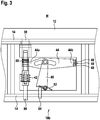
- Fig. 3 shows a cross-sectional view of a sensor unit according to the preferred embodiment of the invention.
- the sensor unit 18b is formed by a deflection sensor configured to perform continuous measurement of a deflection of the form face 12 of the formwork element 10. Moreover, the sensor unit 18b is also configured to measure an oscillation or vibration of the form face 12 of the formwork element 10. This way, information on a vibration and compaction of the concrete can advantageously obtained.
- the form face 12 of the formwork element 10 in this configuration acts as a membrane thus enabling measurement over a significantly larger area than is conventionally the case with pressure sensors.
- the deflection sensor 18b comprises a push rod 38 extending through an opening formed in the support structure 14 adjacent to the form face 12 of the formwork element 10.
- the push rod 38 abuts the form face 12, wherein the push rod 38 is pre-loaded against the form face 12 by a first spring element 42.
- the deflection sensor 18b further comprises a magnet lever 44 connected to the push rod 38 at a first end portion 44a of the magnet lever 44.
- the magnet lever 44 and its second end portion 44b comprises a first permanent magnet 46 and a second permanent magnet 48.
- a hall effect sensor 50 is arranged between the first permanent magnet 46 and the second permanent magnet 48 of the magnet lever 44, wherein the magnet lever 44 is adapted to move upon movement of the push rod 38.
- the hall effect sensor 50 is configured to detect a movement of the magnet lever 44.
- the movements detected by the hall effect sensor 50 can e.g. be movements where the form face 12 returns to its original position after the movement or quick oscillations, i.e. vibrations of the form face 12. This is important information for the concrete worker since he can get information on how much the concrete has been vibrated. Vibration of concrete is an integral part of the casting procedure.
- the magnet lever comprises a slit that is substantially arc-shaped, in which a rod is inserted, that is held by an arm 80 that is preferably fork-shaped, i.e. U-shaped, in order to be able to hold the rod between respective end portions.
- the arm 80 is further held in place by a spring against which an amplification set screw 84 is pushed that extends through the support structure 14 of the formwork element 10.
- the sensor unit 18b further comprises a square nut which follows adjustments of a pre-load screw 86 that extends through the support structure of the formwork element and pre-loads the first spring element 42.
- the preload set screw 86 also conveys the rotary motion to the screw (not numbered) that is in contact with the push rod 38. This has the effect that the preload does not create an offset on the magnet lever 44 since it is fastened to the screw with square nuts having the exact same thread pitch as the preload screw. Preloading the push rod 38 with the preload set screw 86 thus does not change the position of the magnet lever 44.
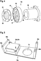
- Fig. 4 shows an exploded view of a further sensor unit according to the preferred embodiment of the invention.
- the sensor unit 18a comprises a pressure transducer holding body 66, a pressure chamber 60, a pressure transducer 67, in particular a pressure transducer, arranged partially within the pressure transducer holding body 66 and inserted partially into the pressure chamber 60 at a first axial end portion of the pressure chamber 60.
- the sensor unit 18a further comprises a membrane 63 covering an opening of the pressure chamber 60 at a second axial end portion of the pressure chamber 60, wherein the pressure chamber 60 contains a hydraulic fluid (not shown in Fig. 4 ) and is configured to contact the building material and to perform continuous measurement of lateral pressure on the form face of the formwork element.
- a hydraulic fluid not shown in Fig. 4
- the pressure transducer holding body 66 further comprises an opening 65 formed at a front face of the pressure transducer holding body.
- the sensor unit 18a moreover comprises a flange 58, wherein in an assembled state of the sensor unit 18a, the flange 58 is screwed to a container portion 64 of the sensor unit 18a that comprises the pressure chamber 60, wherein the membrane 63 is arranged between the flange 58 and the container portion 64.
- the opening 65 in the pressure transducer holding body 66 serves such that a screw can be inserted from a given direction in order to fix the container portion 64 to the pressure transducer holding body 66.
- the pressure transducer holding body 66 pushes against the container portion 64 by the means of two screws through holes marked with arrows in Fig 4 . These screws in effect compresses an o-ring in the o-ring groove 62 in Fig 4 .
- the o-ring creates a water tight seal against the form work element body 14. This solves the problem of how to fasten the sensor assembly without having fasteners subjected to fresh concrete. All assembly and disassembly can be made from the outside of the formwork.
- Fig. 5 shows components of the further sensor unit according to the preferred embodiment of the invention.
- the sensor unit 18a comprises a base plate in which an opening 70 is formed through which the sensor can be inserted.
- the sensor unit 18a furthermore comprises the control unit 20a and the transmission unit 22a, which in the present embodiments are housed within a common housing.
- the sensor unit 18a further comprises mounting means 68a, 68b, 68c, 68d that are adapted to receive screws that may be screwed into said mounting means through a wall of the formwork element (not shown in Fig. 5 ).
- Fig. 6 shows a schematic view of the formwork element comprising the further sensor unit according to the preferred embodiment of the invention.
- the formwork element 10 comprises the support structure 14.
- the support structure is formed by a beam made of a metal material, in particular aluminum, wherein the sensor unit 18a is inserted through an opening of the support structure.
- the sensor unit 18a comprises at an outer surface additionally a USB-connector 74, a status indicating light 78 and a button 76.
- the button has multiple functions.
- the button is used to turn the unit on or off, and reset. It can also be used to "force connect”. That is to create a measurement and connect immediately to the main unit as the button is pushed so as not to wait for the next scheduled measurement.
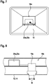
- Fig. 7 shows a schematic view of an inside of the formwork element comprising the further sensor unit according to the preferred embodiment of the invention.
- the sensor unit 18a is arranged at an inside of the support structure, said support structure 14 being made of a profile element that is substantially hollow and has a rectangular cross-section.
- the control unit 20a and the transmission unit 22a are shown which are connected to the USB-connector on the outside of the support structure by means of a cable.
- Fig. 8 shows a cross-sectional view of the formwork element comprising the further sensor unit.
- the sensor unit 18a is shown in assembled state in which it is connected to the control unit 20a and the transmission unit 22a, wherein a membrane 36 extends through an opening 34 of the support structure 14.
- a membrane 36 extends through an opening 34 of the support structure 14.
- Fig. 9 shows a cross-sectional view of a further sensor unit according to the preferred embodiment of the invention.
- Fig. 9 is a modified version of the pressure sensor 18a depicted in Fig. 4 .
- the pressure sensor comprises a pressure chamber 60 that is axially adjustable in position through an opening formed in a base plate 61 of the sensor unit 18a, wherein the sensor unit 18a comprises fixing means 61a configured to lock and unlock the pressure chamber 60 relative to the base plate 61.
- the form face 12 consists of two layers that are arranged back-to-back, said form face being made of a plywood plate. Alternatively the form face 12 may for example be made of steel or plastic.
- the pressure chamber 60a is formed as a fluid filled cavity. Air vent screw 60b communicates with the pressure chamber 60a and is adapted to bleed the pressure chamber 60a.
- the pressure transducer 67 measures a pressure of the fluid disposed in the pressure chamber 60a.
- Fig. 10 shows a schematic view of the further sensor unit depicted in Fig. 9 in a first position according to the preferred embodiment of the invention.
- the pressure chamber is shown in a first position, in which it is substantially retracted.
- Fig. 11 shows a schematic view of the further sensor unit depicted in Fig. 9 in a second position according to the preferred embodiment of the invention.
- the pressure chamber 60 in the present depiction is substantially fully extended. This enables the sensor unit 18a to be also used with thicker formwork elements without having to replace the sensor unit 18a with another sensor unit having longer dimensions.
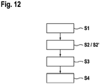
- Fig. 12 shows a flow diagram of a method for predicting stress on the formwork element according to the preferred embodiment of the invention.
- the method comprises the steps of acquiring S1 data in relation to the stress exerted on the formwork element 10 by the building material M by means of at least one sensor unit 18a, 18b, 18c, 18d, 18e of a data acquisition means 16a, 16b, 16c, 16d, 16e.
- the method moreover comprises the step of controlling S2 the at least one sensor unit 18a, 18b, 18c, 18d, 18e by means of a control unit 20a, 20b, 20c, 20d, 20e and/or processing the acquired data S2', wherein the control unit 20a, 20b, 20c, 20d, 20e and the transmission unit 22a, 22b, 22c, 22d, 22e are arranged within the support structure 14, and the at least one sensor unit 18a, 18b, 18c, 18d, 18e is arranged at least partially within the support structure 14.
- the method further comprises the step of transmitting S3 the acquired data to the device 24 located outside the formwork element 10 by the transmission unit 22a, 22b, 22c, 22d, 22e.
- the method further comprises the step of S4 receiving the acquired data by means of the device 24.
Landscapes
- Engineering & Computer Science (AREA)
- Architecture (AREA)
- Physics & Mathematics (AREA)
- General Physics & Mathematics (AREA)
- Aviation & Aerospace Engineering (AREA)
- Mechanical Engineering (AREA)
- Civil Engineering (AREA)
- Structural Engineering (AREA)
- On-Site Construction Work That Accompanies The Preparation And Application Of Concrete (AREA)
Abstract
Description
- The present invention relates to a transmitter for predicting stress on a formwork element. Furthermore, the present invention relates to a system for predicting stress on a formwork element. In addition, the present invention relates to a formwork element for use in a formwork.
- Furthermore, the present invention relates to a method for transmitting data for predicting stress on a formwork element.
- In addition, the present invention relates to a method for predicting stress on a formwork element.
- When pouring a building material into a formwork structure comprising a plurality of formwork elements interconnected to each other, an important aspect is to monitor stress on said formwork elements that is induced into the formwork elements by the building material.
- When casting concrete there is a risk that the concrete form is subjected to loads it cannot handle. This can lead to formwork failure. The concrete formwork geometry could change leading to a flawed end product, for example curved walls or in the worst case scenario, an ultimate collapse of the entire formwork structure.
- An uneven load distribution within the formwork structure could also lead to local failures or an unwanted redistribution of loads. One or more tie rods taking up more load than expected can lead to instant tie rod failure.
- Without knowing the strain or loads the formwork is subjected to, one has to fill the formwork very slowly or divide the pour into multiple stages, letting the concrete harden or at least solidify between each stage.
- Dividing the pour into multiple stages often leads to visible joints, so-called cold joints, or variations of surface color and structure creating an end product of lesser quality.
- Pouring speed and time is not only a factor affecting the physical end result, it is also very closely tied to the economical success of the operation. Hence, it is of interest to the contractor to fill the formwork and do the pour as quick and effective as possible while not jeopardizing the end result or the form place safety.
-
KR 20090016780 -
KR 20130070874 - Consequently, there is a need to further improve systems and methods for predicting stress on a formwork element during and/or after pouring a building material into a space enclosed by a formwork.
- The present invention relates to a transmitter for predicting stress on a formwork element during and/or after pouring a building material, in particular concrete, into a space enclosed by a formwork in accordance with
claim 1, to a system for predicting stress on a formwork element during and/or after pouring a building material, in particular concrete, into a space enclosed by the framework in accordance withclaim 2, to a formwork element for use in a formwork in accordance with claim 7, to a method for transmitting data for predicting stress on a formwork element during and/or after pouring a building material, in particular concrete, into a space enclosed by the formwork in accordance with claim 15 and to a method for predicting stress on a formwork element in accordance with claim 16. - Further embodiments of the present invention are subject of the further sub-claims and of the following description, referring to the drawings.
- An aspect of the present invention relates to a transmitter for predicting stress on a formwork element during and/or after pouring a building material, in particular concrete, into a space enclosed by a formwork including the formwork element, the formwork element comprising a form face and a support structure which is attached to the form face and supporting the form face, wherein the form face is separated from or integrated into the support structure.
- The transmitter comprises the formwork element and data acquisition means comprising at least one sensor unit configured to acquire data in relation to the stress exerted on the formwork element by the building material, a control unit configured to control the at least one sensor unit and/or to process the acquired data, and a transmission unit configured to transmit the acquired data to a device located outside the formwork element, wherein the control unit and the transmission unit are arranged within the support structure, and wherein the at least one sensor unit is arranged at least partially within the support structure.
- A further aspect of the present invention relates to a system for predicting stress on a formwork element during and/or after pouring a building material, in particular concrete, into a space enclosed by a formwork including the formwork element, comprising the transmitter and the device configured to receive the acquired data.
- A further aspect of the present invention relates to a formwork element for use in a formwork, comprising a form face and a support structure which is attached to the form face and supporting the form face, wherein the form face is separated from or integrated into the support structure, the formwork element comprising data acquisition means comprising at least one sensor unit configured to acquire data in relation to the stress exerted on the formwork element by the building material, a control unit configured to control the at least one sensor unit and/or to process the acquired data, and a transmission unit configured to transmit the acquired data to a device located outside the formwork element, wherein the control unit and the transmission unit are arranged within the support structure, and wherein the at least one sensor unit is arranged at least partially within the support structure.
- A further aspect of the present invention relates to a method for transmitting data for predicting stress on a formwork element during and/or after pouring a building material, in particular concrete, into a space enclosed by a formwork including the formwork element, the formwork element comprising a form face and a support structure which is attached to the form face and supporting the form face.
- The form face is separated from or integrated into the support structure, the method comprising the steps of acquiring data in relation to the stress exerted on the formwork element by the building material by means of at least one sensor unit of a data acquisition means, controlling the at least one sensor unit by means of a control unit and/or processing the acquired data, wherein the control unit and the transmission unit are arranged within the support structure.
- The at least one sensor unit is arranged at least partially within the support structure, and transmitting the acquired data to a device located outside the formwork element by a transmission unit.
- A further aspect of the present invention relates to a method for predicting stress on a formwork element during and/or after pouring a building material, in particular concrete, into a space enclosed by a formwork including the formwork element, the method comprising the method for transmitting data for predicting stress on a formwork element according to the invention, and further comprising receiving the acquired data by means of the device.
- The idea of the present invention is to acquire the relevant data by the data acquisition means, process the data and transmit it to a device located outside the formwork element such that a user receives live data on the stress exerted on the formwork elements by the building material being poured into the formwork thus enabling the user to adjust e.g. a pouring speed and other relevant parameters.
- Due to the fact that the system comprises the transmitter, the control unit and the device, a plurality of datasets can be taken into account when analyzing the pour of the building material into the formwork such as known data about the formwork, currently obtained data of the ongoing pour and data on all earlier pours that the system has monitored.
- The properties of standardized formwork parts are well-known to any supplier of such equipment. The properties can be easily described and do not change due to the normal temperature changes, time or any other external factor during normal use. The properties of the formwork form face, the distances between e.g. tie rods and other fasteners in any given section of the formwork are known as well as the dimensions such as height, width, and depth of the formwork construction as a whole.
- The formwork can thus be said to be a system of very well-standardized parts put together in a very well-described way forming a known unit.
- The invention thus uses the concrete form, i.e. the formwork elements, as an integrated monitoring system where the formwork elements themselves act as parts of the sensing mechanism measuring the effect of the fresh concrete pressure on the formwork elements. Information about the formwork elements respective position in the total formwork construction is also used for the analysis.
- According to an embodiment, the device is configured to analyze the data received from the data acquisition means and to display an analysis result to a user via a graphical user interface, and wherein the device is further configured to provide instructions to the user for handling a pouring process.
- The user is thus provided with a simple and easy to use graphical user interface indicating all relevant parameters of the ongoing pour that is capable of providing instructions to the user for making appropriate adjustments.
- According to a further embodiment, the transmission unit is configured to continuously transmit data to the device in duplex communication, and wherein the data is transferrable by cable or wirelessly. Due to the fact that the data is continuously transmitted to the device, accurate and on-time data can be obtained that in turn gives the user an accurate representation of a status of the ongoing pour, in particular with a view to the stress exerted by the building material on the formwork elements.
- According to a further embodiment, the device is configured to perform an analysis of the stress on the formwork element during and/or after pouring the building material using the data received from the data acquisition means, and data of previous building material pours monitored by the system. The system is thus capable of continuously monitoring the stress exerted by the building material on the formwork elements, i.e. during and/or after the pour, as the stress varies during different points in time during and after the pour.
- According to a further embodiment, the system further comprises a data storage unit configured to store the acquired data, and a data interface configured to connect to a further system, in particular a CAD-system for designing formwork structures. The data obtained during and/or after the pour can thus advantageously be used by the CAD-system when designing objects, e.g. buildings and/or formwork structures.
- According to a further embodiment, the at least one sensor unit extends through an opening formed in the support structure, the sensor unit comprising a pressure transducer holding body, a pressure chamber, a pressure sensor, in particular a pressure transducer, arranged at least partially within the pressure transducer holding body and inserted at least partially into or being arranged adjacent to the pressure chamber at a first axial end portion of the pressure chamber and a membrane covering an opening of the pressure chamber at a second axial end portion of the pressure chamber.
- The pressure chamber contains a hydraulic fluid and is configured to contact the building material and to perform continuous measurement of lateral pressure on the form face of the formwork element. Said pressure sensor, in particular the pressure transducer, is thus capable of measuring the concrete pressure at well-defined points by being integrated in the formwork parts, wherein the sensor membrane is in contact with the concrete.
- According to a further embodiment, the pressure chamber is axially adjustable in position through an opening formed in a base plate of the sensor unit, wherein the sensor unit comprises fixing means configured to lock and unlock the pressure chamber relative to the base plate. The adjustability of the pressure chamber and thus of the sensor unit relative to the formwork element thus enables to use only one sensor unit no matter the thickness of the formwork element, in particular the thickness of a plywood plate that forms a form face in contact with the building material.
- According to a further embodiment, the at least one sensor unit is formed by a deflection sensor configured to perform continuous measurement of a deflection of the form face of the formwork element. By being able to measure the deflection of the formwork element by means of the sensor being integrated into the formwork element, an accurate indication of the stress exerted by the building material on the formwork elements can be obtained.
- According to a further embodiment, the deflection sensor comprises a push rod extending through an opening formed in the support structure adjacent to the form face of the formwork element, the push rod abutting the form face, wherein the push rod is pre-loaded against the form face by a first spring element. The deflection sensor can thus measure any changes in the position of the form face in relation to a support structure of the formwork element.
- According to a further embodiment, the deflection sensor further comprises a magnet lever connected to the push rod at a first end portion of the magnet lever, wherein the magnet lever at its second end portion comprises a first permanent magnet and a second permanent magnet, wherein a hall effect sensor is arranged between the first permanent magnet and the second permanent magnet of the magnet lever, wherein the magnet lever is adapted to move upon movement of the push rod, and wherein the hall effect sensor is configured to detect a movement of the magnet lever. By using the hall effect sensor, an accurate measurement of any movement of the lever caused by a movement of the form face of the formwork element can be obtained.
- According to a further development, the at least one sensor unit is formed by a strain gauge configured to measure a load on a tie rod arranged between the formwork element and an adjacent formwork element using compression strain gauge load cells integrated in a tie rod assembly. Thus, an accurate measurement of the load on the tie rod can be performed.
- According to a further development, the at least one sensor unit is formed by a temperature sensor configured to measure a temperature of the building material, wherein the temperature sensor forms contact with the building material or is integrated in the pressure sensor unit, and/or a sound sensor is configured to detect formwork movements using an electrostatic capacitor-based microphone attached to the form face.
- Therefore, advantageously additional data can be obtained by using the temperature sensor and/or the sound sensor that is usable in the overall analysis of the stress exerted on the formwork elements by the building material. In addition, information on loss of workability and hardening of the concrete can advantageously be obtained by means of the temperature sensor and by recording the sound.
- According to a further embodiment, the method for predicting stress on a formwork element further comprises the step of measuring the stress exerted on the formwork at various positions in the formwork by means of a plurality of sensor units. In doing so, a more accurate measurement of various positions across the entire surface of the form phase of the formwork element can be obtained.
- According to a further embodiment, the device is configured to perform an analysis of the stress on the formwork element during and/or after pouring the building material using the data received from the data acquisition means and data of previous building material pours monitored by the system.
- The data obtained during and/or after the pour can thus advantageously be used by the CAD-system when designing objects, e.g. buildings and/or formwork structures.
- The herein described features of the transmitter for predicting stress on a formwork element, the system for predicting stress on a formwork element, the formwork element itself are also disclosed in the method for transmitting data for predicting stress on a formwork element and in the method for predicting stress on a formwork element.
- For a more complete understanding of the present invention and advantages thereof, reference is now made to the following description taken in conjunction with the accompanying drawings. The invention is explained in more detail below using exemplary embodiments, which are specified in the schematic figures of the drawings, in which:
- Fig. 1
- shows a schematic view of a system for predicting stress on a formwork element according to a preferred embodiment of the invention;
- Fig. 2
- shows a cross-sectional view of the formwork element comprising a transmitter and a perspective view of external devices according to the preferred embodiment of the invention;
- Fig. 3
- shows a cross-sectional view of a sensor unit according to the preferred embodiment of the invention;
- Fig. 4
- shows an exploded view of a further sensor unit according to the preferred embodiment of the invention;
- Fig. 5
- shows components of the further sensor unit according to the preferred embodiment of the invention;
- Fig. 6
- shows a schematic view of the formwork element comprising the further sensor unit according to the preferred embodiment of the invention;
- Fig. 7
- shows a schematic view of an inside of the formwork element comprising the further sensor unit according to the preferred embodiment of the invention;
- Fig. 8
- shows a cross-sectional view of the formwork element comprising the further sensor unit;
- Fig. 9
- shows a cross-sectional view of a further sensor unit according to the preferred embodiment of the invention;
- Fig. 10
- shows a schematic view of the further sensor unit depicted in
Fig. 9 in a first position according to the preferred embodiment of the invention; - Fig. 11
- shows a schematic view of the further sensor unit depicted in
Fig. 9 in a second position according to the preferred embodiment of the invention; and - Fig. 12
- shows a flow diagram of a method for predicting stress on the formwork element according to the preferred embodiment of the invention.
- Unless indicated otherwise, like reference numerals or signs to the figures indicate like elements.
-
Fig. 1 shows a schematic view of a system for predicting stress on a formwork element according to a preferred embodiment of the invention. - The
system 1 for predicting stress on aformwork element 10 during and/or after pouring a building material, in particular concrete, into a space enclosed by theformwork 2 is depicted inFig. 1 . Theformwork 2 comprises a plurality ofinterconnected formwork elements 10, eachformwork element 10 comprising aform face 12 and asupport structure 14 supporting theform face 12. -
Fig. 2 shows a cross-sectional view of the formwork element comprising a transmitter and a perspective view of external devices according to the preferred embodiment of the invention. - In
Fig. 2 , building material M, in particular concrete, is poured into the space enclosed by theformwork 2 by means of the pouring device 3. The depictedformwork element 10 comprises theform face 12 and thesupport structure 14 attached to the form face and supporting the form face, wherein the form face is separated from the support structure. Alternatively, the form face may be integrated into thesupport structure 14. - The
system 1 comprises data acquisition means 16a, 16b, 16c, 16d, 16e. The data acquisition means 16a, 16b, 16c, 16d, 16e comprises at least one sensor unit. In the present embodiment, it comprises a plurality ofsensor units formwork element 10 by the building material M. - The
temperature sensor 18d and/or sound sensor 18e can be integrated into the one or more of theother sensors - The
system 1 further comprises a control unit configured to control the sensor unit. In the present embodiment, there are a plurality of control units, each control unit configured to control a dedicated sensor unit. Thecontrol unit control unit sensor unit - The
system 1 further comprises atransmission unit device 24 located outside theformwork element 10. Thecontrol unit transmission unit support structure 14. - Each
sensor unit support structure 14. Alternatively, the sensor unit may be fully embedded into thesupport structure 14. - Moreover, each
sensor unit strain gauge 18c configured to measure a load L on a tie rod 52 arranged between theformwork element 10 and anadjacent formwork element 11 using compression straingauge load cells 54 integrated in a tie rod assembly 56. Alternatively, the compression straingauge load cells 54 can be arranged in the formwork element where the tie rod 52 is inserted. - A
temperature sensor 18d is configured to measure a temperature of the building material M, wherein thetemperature sensor 18d forms contact with the building material M. - Alternatively, the temperature sensor can be integrated in the
pressure sensor unit 18a, and/or a sound sensor 18e configured to detectformwork 2 movements using an electrostatic capacitor-based microphone attached to theform face 12.
The speed of the chemical reactions in the concrete is directly related to the temperature. The sound can be used to determine when the casting started, possibly the location of the concrete surface and the amount of vibration added. Dangerous relocation of the formwork could possibly also be detected. - The
device 24 is configured to analyze the data received from each of the data acquisition means 16a, 16b, 16c, 16d, 16e and to display an analysis result to a user via agraphical user interface 26. Thedevice 24 may alternatively forward the received data to a server (not shown onFig. 2 ) via an internet connection, wherein the server performs the data analysis and provides an analysis result to the device. - The relevant data is acquired by the data acquisition means 16a, processed and transmitted to the
device 24 located outside theformwork element 10 such that a user receives live data on the stress exerted on theformwork element 10 by the building material being poured into the formwork thus enabling the user to adjust e.g. a pouring speed and other relevant parameters. - In addition, e.g. a warning function can be implemented by the
device 24 or a further device (not shown inFig. 2 ) that may warn the user of immediate danger should this be indicated by the data analysis of the stress exerted on theformwork element 10. Said warning may be issued visually and/or acoustically on thedevice 24 and/or another device (not shown inFig. 3 ) such as a warning light and/or a siren located on the construction site. - The
device 24 is further configured to provide instructions to the user for handling a pouring process. Eachtransmission unit device 24 in duplex communication. The data is transferred wirelessly. Alternatively, the data may be transferred by cable. - The
device 24 is configured to perform an analysis of the stress on theformwork element 10 during and after pouring the building material M using the data received from each of the data acquisition means 16a, 16b, 16c, 16d, 16e and data of previous building material pours monitored by the system. Alternatively, said analysis may be performed by other components (not shown) connected to the device. - Alternatively, the
device 24 may be configured to perform the analysis of the stress on theformwork element 10 either during or after pouring the building material. - The
system 1 further comprises adata storage unit 28 that is configured to store the acquired data and adata interface 30 configured to connect to afurther system 32, in particular a CAD-system for designing formwork structures. Thedata storage unit 28 is located at the construction site. Alternatively, thedata storage unit 28 may be embodied as a web-server connected to the device by an internet connection. -
Fig. 3 shows a cross-sectional view of a sensor unit according to the preferred embodiment of the invention. - The
sensor unit 18b is formed by a deflection sensor configured to perform continuous measurement of a deflection of theform face 12 of theformwork element 10. Moreover, thesensor unit 18b is also configured to measure an oscillation or vibration of theform face 12 of theformwork element 10. This way, information on a vibration and compaction of the concrete can advantageously obtained. - The form face 12 of the
formwork element 10 in this configuration acts as a membrane thus enabling measurement over a significantly larger area than is conventionally the case with pressure sensors. - The
deflection sensor 18b comprises apush rod 38 extending through an opening formed in thesupport structure 14 adjacent to theform face 12 of theformwork element 10. - The
push rod 38 abuts theform face 12, wherein thepush rod 38 is pre-loaded against theform face 12 by afirst spring element 42. - The
deflection sensor 18b further comprises amagnet lever 44 connected to thepush rod 38 at afirst end portion 44a of themagnet lever 44. - The
magnet lever 44 and itssecond end portion 44b comprises a firstpermanent magnet 46 and a secondpermanent magnet 48. - A
hall effect sensor 50 is arranged between the firstpermanent magnet 46 and the secondpermanent magnet 48 of themagnet lever 44, wherein themagnet lever 44 is adapted to move upon movement of thepush rod 38. Thehall effect sensor 50 is configured to detect a movement of themagnet lever 44. - The movements detected by the
hall effect sensor 50 can e.g. be movements where theform face 12 returns to its original position after the movement or quick oscillations, i.e. vibrations of theform face 12. This is important information for the concrete worker since he can get information on how much the concrete has been vibrated. Vibration of concrete is an integral part of the casting procedure. - Moreover, the magnet lever comprises a slit that is substantially arc-shaped, in which a rod is inserted, that is held by an
arm 80 that is preferably fork-shaped, i.e. U-shaped, in order to be able to hold the rod between respective end portions. - The
arm 80 is further held in place by a spring against which an amplification setscrew 84 is pushed that extends through thesupport structure 14 of theformwork element 10. - The
sensor unit 18b further comprises a square nut which follows adjustments of apre-load screw 86 that extends through the support structure of the formwork element and pre-loads thefirst spring element 42. - The preload set
screw 86 also conveys the rotary motion to the screw (not numbered) that is in contact with thepush rod 38. This has the effect that the preload does not create an offset on themagnet lever 44 since it is fastened to the screw with square nuts having the exact same thread pitch as the preload screw. Preloading thepush rod 38 with the preload setscrew 86 thus does not change the position of themagnet lever 44. -
Fig. 4 shows an exploded view of a further sensor unit according to the preferred embodiment of the invention. - The
sensor unit 18a comprises a pressuretransducer holding body 66, apressure chamber 60, apressure transducer 67, in particular a pressure transducer, arranged partially within the pressuretransducer holding body 66 and inserted partially into thepressure chamber 60 at a first axial end portion of thepressure chamber 60. - The
sensor unit 18a further comprises amembrane 63 covering an opening of thepressure chamber 60 at a second axial end portion of thepressure chamber 60, wherein thepressure chamber 60 contains a hydraulic fluid (not shown inFig. 4 ) and is configured to contact the building material and to perform continuous measurement of lateral pressure on the form face of the formwork element. - The pressure
transducer holding body 66 further comprises anopening 65 formed at a front face of the pressure transducer holding body. Thesensor unit 18a moreover comprises aflange 58, wherein in an assembled state of thesensor unit 18a, theflange 58 is screwed to acontainer portion 64 of thesensor unit 18a that comprises thepressure chamber 60, wherein themembrane 63 is arranged between theflange 58 and thecontainer portion 64. Theopening 65 in the pressuretransducer holding body 66 serves such that a screw can be inserted from a given direction in order to fix thecontainer portion 64 to the pressuretransducer holding body 66. - This is a very light press-fit. Pressure is then applied to compress the o-ring in an o-
ring groove 62 using the screws mentioned in the comment above. - The pressure
transducer holding body 66 pushes against thecontainer portion 64 by the means of two screws through holes marked with arrows inFig 4 . These screws in effect compresses an o-ring in the o-ring groove 62 inFig 4 . The o-ring creates a water tight seal against the formwork element body 14. This solves the problem of how to fasten the sensor assembly without having fasteners subjected to fresh concrete. All assembly and disassembly can be made from the outside of the formwork. -
Fig. 5 shows components of the further sensor unit according to the preferred embodiment of the invention. - The
sensor unit 18a comprises a base plate in which anopening 70 is formed through which the sensor can be inserted. Thesensor unit 18a furthermore comprises thecontrol unit 20a and thetransmission unit 22a, which in the present embodiments are housed within a common housing. Thesensor unit 18a further comprises mountingmeans Fig. 5 ). -
Fig. 6 shows a schematic view of the formwork element comprising the further sensor unit according to the preferred embodiment of the invention. - The
formwork element 10 comprises thesupport structure 14. In the present embodiment, the support structure is formed by a beam made of a metal material, in particular aluminum, wherein thesensor unit 18a is inserted through an opening of the support structure. Thesensor unit 18a comprises at an outer surface additionally a USB-connector 74, astatus indicating light 78 and abutton 76. - The button has multiple functions. The button is used to turn the unit on or off, and reset. It can also be used to "force connect". That is to create a measurement and connect immediately to the main unit as the button is pushed so as not to wait for the next scheduled measurement.
- Alternatively, other buttons having other functions may be placed on the outside of the
sensor unit 18a.
Fig. 7 shows a schematic view of an inside of the formwork element comprising the further sensor unit according to the preferred embodiment of the invention. - The
sensor unit 18a is arranged at an inside of the support structure, saidsupport structure 14 being made of a profile element that is substantially hollow and has a rectangular cross-section. Thecontrol unit 20a and thetransmission unit 22a are shown which are connected to the USB-connector on the outside of the support structure by means of a cable. -
Fig. 8 shows a cross-sectional view of the formwork element comprising the further sensor unit. - The
sensor unit 18a is shown in assembled state in which it is connected to thecontrol unit 20a and thetransmission unit 22a, wherein amembrane 36 extends through anopening 34 of thesupport structure 14. Thus, building material M that is being poured into the space enclosed by respective formwork elements exerts a substantially lateral pressure on saidmembrane 36 of thesensor unit 18a. -
Fig. 9 shows a cross-sectional view of a further sensor unit according to the preferred embodiment of the invention.Fig. 9 is a modified version of thepressure sensor 18a depicted inFig. 4 . In the present embodiment, the pressure sensor comprises apressure chamber 60 that is axially adjustable in position through an opening formed in abase plate 61 of thesensor unit 18a, wherein thesensor unit 18a comprises fixing means 61a configured to lock and unlock thepressure chamber 60 relative to thebase plate 61. Moreover, theform face 12 consists of two layers that are arranged back-to-back, said form face being made of a plywood plate. Alternatively theform face 12 may for example be made of steel or plastic. - The
pressure chamber 60a is formed as a fluid filled cavity.Air vent screw 60b communicates with thepressure chamber 60a and is adapted to bleed thepressure chamber 60a. - The
pressure transducer 67 measures a pressure of the fluid disposed in thepressure chamber 60a. -
Fig. 10 shows a schematic view of the further sensor unit depicted inFig. 9 in a first position according to the preferred embodiment of the invention. In the present view, the pressure chamber is shown in a first position, in which it is substantially retracted. -
Fig. 11 shows a schematic view of the further sensor unit depicted inFig. 9 in a second position according to the preferred embodiment of the invention. - The
pressure chamber 60 in the present depiction is substantially fully extended. This enables thesensor unit 18a to be also used with thicker formwork elements without having to replace thesensor unit 18a with another sensor unit having longer dimensions. -
Fig. 12 shows a flow diagram of a method for predicting stress on the formwork element according to the preferred embodiment of the invention. - The method comprises the steps of acquiring S1 data in relation to the stress exerted on the
formwork element 10 by the building material M by means of at least onesensor unit - The method moreover comprises the step of controlling S2 the at least one
sensor unit control unit control unit transmission unit support structure 14, and the at least onesensor unit support structure 14. - The method further comprises the step of transmitting S3 the acquired data to the
device 24 located outside theformwork element 10 by thetransmission unit - The method further comprises the step of S4 receiving the acquired data by means of the
device 24. - Although the afore-mentioned system has been described in connection with formwork elements of a formwork structure, a person skilled in the art is aware of the fact that the herein described system can of course be applied to other structures in which a stress of a medium against a containing structure is to be monitored.
- Although specific embodiments have been illustrated and described herein, it will be appreciated by those of ordinary skill in the art that a variety of alternate and/or equivalent implementations exist. It should be appreciated that the exemplary embodiment or exemplary embodiments are only examples, and are not intended to limit the scope, applicability, or configuration in any way.
- Rather, the foregoing summary and detailed description will provide those skilled in the art with a convenient road map for implementing at least one exemplary embodiment, it being understood that various changes may be made in the function and arrangement of elements described in an exemplary embodiment without departing from the scope as set forth in the appended claims and their legal equivalents.
- Generally, this application is intended to cover any adaptations or variations of the specific embodiments discussed herein.
-
- 1
- system
- 2
- formwork
- 3
- pouring device
- 10
- formwork element
- 12
- form face
- 14
- support structure
- 16a, 16b, 16c, 16d, 16e
- data acquisition means
- 18a, 18b, 18c, 18d, 18e
- sensor unit
- 20a, 20b, 20c, 20d, 20e
- control unit
- 22a, 22b, 22c, 22d, 22e
- transmission unit
- 24
- device
- 26
- graphical user interface
- 28
- storage unit
- 30
- data interface
- 32
- further system
- 34
- opening
- 36
- membrane
- 38
- push rod
- 40
- opening
- 44
- magnet lever
- 44a
- first end portion
- 44b
- second end portion
- 46
- first permanent magnet
- 48
- second permanent magnet
- 50
- hall effect sensor
- 52
- tie rod
- 54
- compression strain gauge load cells
- 56
- tie rod assembly
- 58
- flange
- 60, 60a
- pressure chamber
- 60b
- air vent screw
- 61
- base plate
- 61a
- fixing means
- 62
- o-ring groove
- 63
- membrane
- 64
- containing portion
- 65
- opening
- 66
- pressure transducer holding body
- 67
- pressure transducer
- 68a, 68b, 68c, 68d
- mounting means
- 70
- opening
- 74
- connector
- 76
- button
- 78
- status indicating light
- 80
- arm
- 84
- amplification set screw
- 86
- pre-load screw
- M
- building material
- P
- lateral pressure
Claims (18)
- Transmitter for predicting stress on a formwork element (10) during and/or after pouring a building material (M), in particular concrete, into a space enclosed by a formwork (2) including the formwork element (10), the formwork element (10) comprising a form face (12) and a support structure (14) which is attached to the form face (12) and supporting the form face (12), wherein the form face (12) is separated from or integrated into the support structure (14), the transmitter comprising:the formwork element (10); anddata acquisition means (16a, 16b, 16c, 16d, 16e) comprising at least one sensor unit (18a, 18b, 18c, 18d, 18e) configured to acquire data in relation to the stress exerted on the formwork element (10) by the building material (M), a control unit (20a, 20b, 20c, 20d, 20e) configured to control the at least one sensor unit (18a, 18b, 18c, 18d, 18e) and/or to process the acquired data, and a transmission unit (22a, 22b, 22c, 22d, 22e) configured to transmit the acquired data to a device (24) located outside the formwork element (10), wherein the control unit (20a, 20b, 20c, 20d, 20e) and the transmission unit (22a, 22b, 22c, 22d, 22e) are arranged within the support structure (14), and wherein the at least one sensor unit (18a, 18b, 18c, 18d, 18e) is arranged at least partially within the support structure (14) .
- System (1) for predicting stress on a formwork element (10) during and/or after pouring a building material (M), in particular concrete, into a space enclosed by a formwork (2) including the formwork element (10), comprising the transmitter of claim 1 and the device (24) configured to receive the acquired data.
- The system of claim 2, wherein the device (24) is configured to analyze the data received from the data acquisition means (16a, 16b, 16c, 16d, 16e) and to display an analysis result to a user via a graphical user interface (26), and wherein the device (24) is further configured to provide instructions to the user for handling a pouring process.
- The system of claim 2 or 3, wherein the transmission unit (22a, 22b, 22c, 22d, 22e) is configured to continuously transmit data to the device (24) in duplex communication, and wherein the data is transferable by cable or wirelessly.
- The system of claim 3 or 4, wherein the device (24) is configured to perform an analysis of the stress on the formwork element (10) during and/or after pouring the building material (M) using the data received from the data acquisition means (16a, 16b, 16c, 16d, 16e) and data of previous building material (M) pours monitored by the system.
- The system of any one of claims 2 to 5, further comprising a data storage unit (28) configured to store the acquired data, and a data interface (30) configured to connect to a further system (32), in particular a CAD-system for designing formwork structures.
- Formwork element (10) for use in a formwork (2), comprising a form face (12) and a support structure (14) which is attached to the form face (12) and supporting the form face (12), wherein the form face (12) is separated from or integrated into the support structure (14), the formwork element (10) comprising data acquisition means (16a, 16b, 16c, 16d, 16e) comprising at least one sensor unit (18a, 18b, 18c, 18d, 18e) configured to acquire data in relation to the stress exerted on the formwork element (10) by the building material (M), a control unit (20a, 20b, 20c, 20d, 20e) configured to control the at least one sensor unit (18a, 18b, 18c, 18d, 18e) and/or to process the acquired data, and a transmission unit (22a, 22b, 22c, 22d, 22e) configured to transmit the acquired data to a device (24) located outside the formwork element (10), wherein the control unit (20a, 20b, 20c, 20d, 20e) and the transmission unit (22a, 22b, 22c, 22d, 22e) are arranged within the support structure (14), and wherein the at least one sensor unit (18a, 18b, 18c, 18d, 18e) is arranged at least partially within the support structure (14) .
- The formwork element of claim 7, wherein the at least one sensor unit (18a) extends through an opening (34) formed in the support structure (14), the sensor unit (18a) comprising a pressure transducer holding body (66), a pressure chamber (60), a pressure transducer (67) arranged at least partially within the pressure transducer holding body (66) and inserted at least partially into or being arranged adjacent to the pressure chamber (60) at a first axial end portion of the pressure chamber (60) and a membrane (63) covering an opening of the pressure chamber (60) at a second axial end portion of the pressure chamber (60), wherein the pressure chamber (60) contains a hydraulic fluid and is configured to contact the building material (M) and to perform continuous measurement of lateral pressure (P) on the form face (12) of the formwork element (10).
- The formwork element of claim 8, wherein the pressure chamber (66) is axially adjustable in position through an opening formed in a base plate (61) of the sensor unit (18a), wherein the sensor unit (18a) comprises fixing means (61a) configured to lock and unlock the pressure chamber (66) relative to the base plate (61).
- The formwork element of claim 7, wherein the at least one sensor unit (18a, 18b, 18c, 18d, 18e) is formed by a deflection sensor (18b) configured to perform continuous measurement of a deflection of the form face (12) of the formwork element (10).
- The formwork element of claim 10, wherein the deflection sensor (18b) comprises a push rod (38) extending through an opening (40) formed in the support structure (14) adjacent to the form face (12) of the formwork element (10), the push rod (38) abutting the form face (12), wherein the push rod (38) is pre-loaded against the form face (12) by a first spring element (42) .
- The formwork element of claim 11, wherein the deflection sensor (18b) further comprises a magnet lever (44) connected to the push rod (38) at a first end portion (44a) of the magnet lever (44), wherein the magnet lever (44) at its second end portion (44b) comprises a first permanent magnet (46) and a second permanent magnet (48), wherein a hall effect sensor (50) is arranged between the first permanent magnet (46) and the second permanent magnet (48) of the magnet lever (44), wherein the magnet lever (44) is adapted to move upon movement of the push rod (38), and wherein the hall effect sensor (50) is configured to detect a movement of the magnet lever (44).
- The formwork element of any one of claims 7 to 12, wherein the at least one sensor unit (18a, 18b, 18c, 18d, 18e) is formed by a strain gauge (18c) configured to measure a load (L) on a tie rod (52) arranged between the formwork element (10) and an adjacent formwork element (11) using compression strain gauge load cells (54) integrated in a tie rod assembly (56).
- The formwork element of any one of claims 7 to 13, wherein the at least one sensor unit (18a, 18b, 18c, 18d, 18e) is formed by a temperature sensor (18d) configured to measure a temperature of the building material (M), wherein the temperature sensor (18d) forms contact with the building material (M) or is integrated in the pressure sensor unit (18a), and/or a sound sensor (18e) configured to detect formwork (2) movements using an electrostatic capacitor-based microphone attached to the form face (12).
- Method for transmitting data for predicting stress on a formwork element (10) during and/or after pouring a building material (M), in particular concrete, into a space enclosed by a formwork (2) including the formwork element (10), the formwork element (10) comprising a form face (12) and a support structure (14) which is attached to the form face (12) and supporting the form face (12), wherein the form face (12) is separated from or integrated into the support structure (14), the method comprising the steps of:acquiring data (S1) in relation to the stress exerted on the formwork element (10) by the building material (M) by means of at least one sensor unit (18a, 18b, 18c, 18d, 18e) of a data acquisition means (16a, 16b, 16c, 16d, 16e) ;controlling (S2) the at least one sensor unit (18a, 18b, 18c, 18d, 18e) by means of a control unit (20a, 20b, 20c, 20d, 20e) and/or processing the acquired data (S2'), wherein the control unit (20a, 20b, 20c, 20d, 20e) and the transmission unit (22a, 22b, 22c, 22d, 22e) are arranged within the support structure (14), and the at least one sensor unit (18a, 18b, 18c, 18d, 18e) is arranged at least partially within the support structure (14); andtransmitting (S3) the acquired data to a device (24) located outside the formwork element (10) by a transmission unit (22a, 22b, 22c, 22d, 22e).
- Method for predicting stress on a formwork element (10) during and/or after pouring a building material (M), in particular concrete, into a space enclosed by a formwork (2) including the formwork element (10), the method comprising the method for transmitting data for predicting stress on a formwork element (10) of claim 14, and further comprising:
receiving (S4) the acquired data by means of the device (24) . - Method of claim 15 or 16, further comprising the step of measuring the stress exerted on the formwork (2) at various positions in the formwork (2) by means of a plurality of sensor units (18a, 18b, 18c, 18d, 18e).
- Method of claim 16 or 17, wherein the device (24) is configured to perform an analysis of the stress on the formwork element (10) during and/or after pouring the building material (M) using the data received from the data acquisition means (16a, 16b, 16c, 16d, 16e) and data of previous building material (M) pours monitored by the system.
Priority Applications (7)
| Application Number | Priority Date | Filing Date | Title |
|---|---|---|---|
| PL18210078.4T PL3663484T3 (en) | 2018-12-04 | 2018-12-04 | System and method for transmitting data for performing an analysis of stress on a formwork element |
| EP18210078.4A EP3663484B1 (en) | 2018-12-04 | 2018-12-04 | System and method for transmitting data for performing an analysis of stress on a formwork element |
| DK18210078.4T DK3663484T3 (en) | 2018-12-04 | 2018-12-04 | DATA TRANSMISSION SYSTEM AND METHOD FOR PERFORMING A LOAD ANALYSIS ON A FORMWORK ELEMENT |
| US17/311,218 US11774317B2 (en) | 2018-12-04 | 2019-11-11 | Transmitter, system, formwork element, method for transmitting data and method for predicting stress on a formwork element |
| CA3119527A CA3119527A1 (en) | 2018-12-04 | 2019-11-11 | Transmitter, system, formwork element, method for transmitting data and method for predicting stress on a formwork element |
| PCT/EP2019/080832 WO2020114721A1 (en) | 2018-12-04 | 2019-11-11 | Transmitter, system, formwork element, method for transmitting data and method for predicting stress on a formwork element |
| US18/453,677 US20230393019A1 (en) | 2018-12-04 | 2023-08-22 | Transmitter, system, formwork element, method for transmitting data and method for predicting stress on a formwork element |
Applications Claiming Priority (1)
| Application Number | Priority Date | Filing Date | Title |
|---|---|---|---|
| EP18210078.4A EP3663484B1 (en) | 2018-12-04 | 2018-12-04 | System and method for transmitting data for performing an analysis of stress on a formwork element |
Publications (2)
| Publication Number | Publication Date |
|---|---|
| EP3663484A1 true EP3663484A1 (en) | 2020-06-10 |
| EP3663484B1 EP3663484B1 (en) | 2022-09-07 |
Family
ID=64604535
Family Applications (1)
| Application Number | Title | Priority Date | Filing Date |
|---|---|---|---|
| EP18210078.4A Active EP3663484B1 (en) | 2018-12-04 | 2018-12-04 | System and method for transmitting data for performing an analysis of stress on a formwork element |
Country Status (6)
| Country | Link |
|---|---|
| US (2) | US11774317B2 (en) |
| EP (1) | EP3663484B1 (en) |
| CA (1) | CA3119527A1 (en) |
| DK (1) | DK3663484T3 (en) |
| PL (1) | PL3663484T3 (en) |
| WO (1) | WO2020114721A1 (en) |
Cited By (3)
| Publication number | Priority date | Publication date | Assignee | Title |
|---|---|---|---|---|
| DE102020106843A1 (en) | 2020-03-12 | 2021-09-16 | Peri Gmbh | Formwork system, anchor device, anchor rod, use of anchor rod and method |
| CN114593864A (en) * | 2022-03-09 | 2022-06-07 | 中国船舶重工集团公司第七0三研究所 | Hydraulic sensor for thermal power plant thermodynamic system |
| US11536040B2 (en) * | 2016-01-31 | 2022-12-27 | Romeo Ilarian Ciuperca | Self-annealing concrete, self-annealing concrete forms, temperature monitoring system for self-annealing concrete forms and method of making and using same |
Families Citing this family (4)
| Publication number | Priority date | Publication date | Assignee | Title |
|---|---|---|---|---|
| CN115726563B (en) * | 2022-11-04 | 2025-07-18 | 上海建工五建集团有限公司 | Template with illumination and elevation measurement functions and construction method thereof |
| WO2024117836A1 (en) * | 2022-12-01 | 2024-06-06 | 안경호 | Mold fastening clamp |
| AU2024233554A1 (en) * | 2023-03-05 | 2025-10-09 | IQM Systems Pty Ltd | Formwork pressure measurement device and monitoring system |
| CN117967033A (en) * | 2024-02-01 | 2024-05-03 | 中国十九冶集团有限公司 | Formwork system for reinforced concrete pouring and construction method thereof |
Citations (7)
| Publication number | Priority date | Publication date | Assignee | Title |
|---|---|---|---|---|
| KR20090016780A (en) | 2007-08-13 | 2009-02-18 | 금호산업주식회사 | Formwork strain detection device |
| KR20130070874A (en) | 2011-12-20 | 2013-06-28 | (주) 희림종합건축사사무소 | Detecting apparatus and method for signs of form collapse |
| DE102016212220A1 (en) * | 2015-07-07 | 2017-01-12 | Ifm Electronic Gmbh | Arrangement of a measuring device and a container |
| EP3216979A1 (en) * | 2016-03-07 | 2017-09-13 | Kern Tunneltechnik SA | Shuttering system |
| CN206636208U (en) * | 2017-04-08 | 2017-11-14 | 青岛康太源建设集团有限公司 | It is a kind of can improve shear wall root construction quality steel back it is stupefied |
| KR20180023149A (en) * | 2016-08-24 | 2018-03-07 | 현대건설주식회사 | Slip Form with a Pressure sensor, Concrete Cast-in Apparatus Using Thereof and Method Thereof |
| EP3404205A1 (en) * | 2017-05-19 | 2018-11-21 | MEVA Schalungs-Systeme GmbH | Concrete manometer and concrete manometer assembly |
Family Cites Families (5)
| Publication number | Priority date | Publication date | Assignee | Title |
|---|---|---|---|---|
| US3627943A (en) * | 1969-05-15 | 1971-12-14 | Netstal Ag Maschf Giesserei | Toolholding arrangement including improved control signal producing means |
| CA1305769C (en) * | 1986-11-04 | 1992-07-28 | Nobuyuki Yamazaki | Method for predicting and controlling the strength development of concrete and apparatus therefor |
| JPH06322816A (en) * | 1993-05-19 | 1994-11-22 | Shimizu Corp | Precast concrete formwork |
| JP2764785B2 (en) * | 1994-02-07 | 1998-06-11 | 株式会社大林組 | Formwork coupling |
| DE202008011345U1 (en) * | 2008-08-19 | 2008-12-18 | Technische Universität Dresden | Communication means for building components and elements for building construction |
-
2018
- 2018-12-04 PL PL18210078.4T patent/PL3663484T3/en unknown
- 2018-12-04 DK DK18210078.4T patent/DK3663484T3/en active
- 2018-12-04 EP EP18210078.4A patent/EP3663484B1/en active Active
-
2019
- 2019-11-11 CA CA3119527A patent/CA3119527A1/en active Pending
- 2019-11-11 WO PCT/EP2019/080832 patent/WO2020114721A1/en not_active Ceased
- 2019-11-11 US US17/311,218 patent/US11774317B2/en active Active
-
2023
- 2023-08-22 US US18/453,677 patent/US20230393019A1/en not_active Abandoned
Patent Citations (7)
| Publication number | Priority date | Publication date | Assignee | Title |
|---|---|---|---|---|
| KR20090016780A (en) | 2007-08-13 | 2009-02-18 | 금호산업주식회사 | Formwork strain detection device |
| KR20130070874A (en) | 2011-12-20 | 2013-06-28 | (주) 희림종합건축사사무소 | Detecting apparatus and method for signs of form collapse |
| DE102016212220A1 (en) * | 2015-07-07 | 2017-01-12 | Ifm Electronic Gmbh | Arrangement of a measuring device and a container |
| EP3216979A1 (en) * | 2016-03-07 | 2017-09-13 | Kern Tunneltechnik SA | Shuttering system |
| KR20180023149A (en) * | 2016-08-24 | 2018-03-07 | 현대건설주식회사 | Slip Form with a Pressure sensor, Concrete Cast-in Apparatus Using Thereof and Method Thereof |
| CN206636208U (en) * | 2017-04-08 | 2017-11-14 | 青岛康太源建设集团有限公司 | It is a kind of can improve shear wall root construction quality steel back it is stupefied |
| EP3404205A1 (en) * | 2017-05-19 | 2018-11-21 | MEVA Schalungs-Systeme GmbH | Concrete manometer and concrete manometer assembly |
Non-Patent Citations (1)
| Title |
|---|
| PERI GMBH: "Self-Leveling Slab Formwork Tables Boost Efficiency", CONCRETE INTERNATIONAL, 30 June 2011 (2011-06-30), pages 1 - 3, XP055582393, Retrieved from the Internet <URL:http://www.largoconcrete.com/wp-content/uploads/2017/04/2011-Self-Leveling-Slab-Formwork-Tables.pdf> [retrieved on 20190418] * |
Cited By (6)
| Publication number | Priority date | Publication date | Assignee | Title |
|---|---|---|---|---|
| US11536040B2 (en) * | 2016-01-31 | 2022-12-27 | Romeo Ilarian Ciuperca | Self-annealing concrete, self-annealing concrete forms, temperature monitoring system for self-annealing concrete forms and method of making and using same |
| US20230128237A1 (en) * | 2016-01-31 | 2023-04-27 | Romeo Ilarian Ciuperca | Self-annealing concrete, self-annealing concrete forms, temperature monitoring system for self-annealing concrete forms and method of making and using same |
| US12000161B2 (en) * | 2016-01-31 | 2024-06-04 | Romeo Ilarian Ciuperca | Self-annealing concrete, self-annealing concrete forms, and temperature monitoring system for self-annealing concrete forms |
| DE102020106843A1 (en) | 2020-03-12 | 2021-09-16 | Peri Gmbh | Formwork system, anchor device, anchor rod, use of anchor rod and method |
| CN114593864A (en) * | 2022-03-09 | 2022-06-07 | 中国船舶重工集团公司第七0三研究所 | Hydraulic sensor for thermal power plant thermodynamic system |
| CN114593864B (en) * | 2022-03-09 | 2024-05-17 | 中国船舶重工集团公司第七0三研究所 | Hydraulic sensor for thermal power plant thermodynamic system |
Also Published As
| Publication number | Publication date |
|---|---|
| US20230393019A1 (en) | 2023-12-07 |
| DK3663484T3 (en) | 2022-10-03 |
| CA3119527A1 (en) | 2020-06-11 |
| US20220026306A1 (en) | 2022-01-27 |
| PL3663484T3 (en) | 2022-11-07 |
| US11774317B2 (en) | 2023-10-03 |
| WO2020114721A1 (en) | 2020-06-11 |
| EP3663484B1 (en) | 2022-09-07 |
Similar Documents
| Publication | Publication Date | Title |
|---|---|---|
| US20230393019A1 (en) | Transmitter, system, formwork element, method for transmitting data and method for predicting stress on a formwork element | |
| US11835490B2 (en) | Device and method for detecting grout compactness of splice sleeve | |
| EP1785703B1 (en) | Method for monitoring and/or determining the condition of a force measuring device and force measuring device | |
| JP2008096416A (en) | Calibration method for tension force detector | |
| TWI826551B (en) | Determination system, determination program, determination method and learning system for sealing construction | |
| US11402287B2 (en) | Mechanical formwork pressure sensor for in-situ measurement of fluid pressure during concrete matertal placement and method of using the same | |
| KR102395016B1 (en) | System for real-time monitoring collapse risk of support and Method thereof | |
| JP2011185620A (en) | Measuring device of elastic modulus of concrete | |
| KR101184048B1 (en) | Early-age concrete strength estimation apparatus and method for using impedance | |
| JP4825599B2 (en) | Damage detection method, damage detection device, damage detection system | |
| KR101685558B1 (en) | Diagnosis and Disaster Warning Device of a Building Using a Reinforced Concrete Construction | |
| KR100822369B1 (en) | Rebar corrosion check device for safety diagnosis of reinforced concrete structures | |
| EP2572174B1 (en) | Method and apparatus for internally determining a load applied by a jack | |
| EP2025819A1 (en) | Device for measuring movement of components that are sensitive to settlement | |
| JP2024127435A (en) | Vibration Monitoring System | |
| JP2009083353A (en) | Concrete placement management method and concrete placement management system | |
| CA3020386A1 (en) | Method and investigation device for measuring stresses in an agglomerate structure | |
| KR102804957B1 (en) | Monitoring system and method for ground improvement site | |
| Dong et al. | High-speed heterogeneous data acquisition using Martlet-A next-generation wireless sensing node | |
| AU2024233554A1 (en) | Formwork pressure measurement device and monitoring system | |
| KR20180079636A (en) | System and method for monitoring operation information in construction equipment | |
| JPH10102776A (en) | Method and device for measuring tension of pc steel bar for prestressed concrete | |
| KR102174774B1 (en) | Apparatus and Method for Measuring Buried Depth of Anchor Bolt in Concrete of Bridge | |
| WO2002023151A3 (en) | Multisensor array for controlling structures | |
| JPH0797055B2 (en) | Lateral pressure measurement device |
Legal Events
| Date | Code | Title | Description |
|---|---|---|---|
| PUAI | Public reference made under article 153(3) epc to a published international application that has entered the european phase |
Free format text: ORIGINAL CODE: 0009012 |
|
| STAA | Information on the status of an ep patent application or granted ep patent |
Free format text: STATUS: THE APPLICATION HAS BEEN PUBLISHED |
|
| AK | Designated contracting states |
Kind code of ref document: A1 Designated state(s): AL AT BE BG CH CY CZ DE DK EE ES FI FR GB GR HR HU IE IS IT LI LT LU LV MC MK MT NL NO PL PT RO RS SE SI SK SM TR |
|
| AX | Request for extension of the european patent |
Extension state: BA ME |
|
| STAA | Information on the status of an ep patent application or granted ep patent |
Free format text: STATUS: REQUEST FOR EXAMINATION WAS MADE |
|
| 17P | Request for examination filed |
Effective date: 20201208 |
|
| RBV | Designated contracting states (corrected) |
Designated state(s): AL AT BE BG CH CY CZ DE DK EE ES FI FR GB GR HR HU IE IS IT LI LT LU LV MC MK MT NL NO PL PT RO RS SE SI SK SM TR |
|
| STAA | Information on the status of an ep patent application or granted ep patent |
Free format text: STATUS: EXAMINATION IS IN PROGRESS |
|
| 17Q | First examination report despatched |
Effective date: 20210419 |
|
| GRAP | Despatch of communication of intention to grant a patent |
Free format text: ORIGINAL CODE: EPIDOSNIGR1 |
|
| STAA | Information on the status of an ep patent application or granted ep patent |
Free format text: STATUS: GRANT OF PATENT IS INTENDED |
|
| INTG | Intention to grant announced |
Effective date: 20220330 |
|
| GRAS | Grant fee paid |
Free format text: ORIGINAL CODE: EPIDOSNIGR3 |
|
| GRAA | (expected) grant |
Free format text: ORIGINAL CODE: 0009210 |
|
| STAA | Information on the status of an ep patent application or granted ep patent |
Free format text: STATUS: THE PATENT HAS BEEN GRANTED |
|
| RAP1 | Party data changed (applicant data changed or rights of an application transferred) |
Owner name: PERI SE |
|
| AK | Designated contracting states |
Kind code of ref document: B1 Designated state(s): AL AT BE BG CH CY CZ DE DK EE ES FI FR GB GR HR HU IE IS IT LI LT LU LV MC MK MT NL NO PL PT RO RS SE SI SK SM TR |
|
| REG | Reference to a national code |
Ref country code: GB Ref legal event code: FG4D |
|
| REG | Reference to a national code |
Ref country code: CH Ref legal event code: EP Ref country code: AT Ref legal event code: REF Ref document number: 1517163 Country of ref document: AT Kind code of ref document: T Effective date: 20220915 |
|
| REG | Reference to a national code |
Ref country code: IE Ref legal event code: FG4D |
|
| REG | Reference to a national code |
Ref country code: DE Ref legal event code: R096 Ref document number: 602018040272 Country of ref document: DE |
|
| REG | Reference to a national code |
Ref country code: DK Ref legal event code: T3 Effective date: 20220929 |
|
| REG | Reference to a national code |
Ref country code: SE Ref legal event code: TRGR |
|
| REG | Reference to a national code |
Ref country code: LT Ref legal event code: MG9D |
|
| REG | Reference to a national code |
Ref country code: NL Ref legal event code: MP Effective date: 20220907 |
|
| PG25 | Lapsed in a contracting state [announced via postgrant information from national office to epo] |
Ref country code: RS Free format text: LAPSE BECAUSE OF FAILURE TO SUBMIT A TRANSLATION OF THE DESCRIPTION OR TO PAY THE FEE WITHIN THE PRESCRIBED TIME-LIMIT Effective date: 20220907 Ref country code: NO Free format text: LAPSE BECAUSE OF FAILURE TO SUBMIT A TRANSLATION OF THE DESCRIPTION OR TO PAY THE FEE WITHIN THE PRESCRIBED TIME-LIMIT Effective date: 20221207 Ref country code: LV Free format text: LAPSE BECAUSE OF FAILURE TO SUBMIT A TRANSLATION OF THE DESCRIPTION OR TO PAY THE FEE WITHIN THE PRESCRIBED TIME-LIMIT Effective date: 20220907 Ref country code: LT Free format text: LAPSE BECAUSE OF FAILURE TO SUBMIT A TRANSLATION OF THE DESCRIPTION OR TO PAY THE FEE WITHIN THE PRESCRIBED TIME-LIMIT Effective date: 20220907 Ref country code: FI Free format text: LAPSE BECAUSE OF FAILURE TO SUBMIT A TRANSLATION OF THE DESCRIPTION OR TO PAY THE FEE WITHIN THE PRESCRIBED TIME-LIMIT Effective date: 20220907 |
|
| PG25 | Lapsed in a contracting state [announced via postgrant information from national office to epo] |
Ref country code: HR Free format text: LAPSE BECAUSE OF FAILURE TO SUBMIT A TRANSLATION OF THE DESCRIPTION OR TO PAY THE FEE WITHIN THE PRESCRIBED TIME-LIMIT Effective date: 20220907 Ref country code: GR Free format text: LAPSE BECAUSE OF FAILURE TO SUBMIT A TRANSLATION OF THE DESCRIPTION OR TO PAY THE FEE WITHIN THE PRESCRIBED TIME-LIMIT Effective date: 20221208 |
|
| PG25 | Lapsed in a contracting state [announced via postgrant information from national office to epo] |
Ref country code: SM Free format text: LAPSE BECAUSE OF FAILURE TO SUBMIT A TRANSLATION OF THE DESCRIPTION OR TO PAY THE FEE WITHIN THE PRESCRIBED TIME-LIMIT Effective date: 20220907 Ref country code: RO Free format text: LAPSE BECAUSE OF FAILURE TO SUBMIT A TRANSLATION OF THE DESCRIPTION OR TO PAY THE FEE WITHIN THE PRESCRIBED TIME-LIMIT Effective date: 20220907 Ref country code: PT Free format text: LAPSE BECAUSE OF FAILURE TO SUBMIT A TRANSLATION OF THE DESCRIPTION OR TO PAY THE FEE WITHIN THE PRESCRIBED TIME-LIMIT Effective date: 20230109 Ref country code: ES Free format text: LAPSE BECAUSE OF FAILURE TO SUBMIT A TRANSLATION OF THE DESCRIPTION OR TO PAY THE FEE WITHIN THE PRESCRIBED TIME-LIMIT Effective date: 20220907 Ref country code: CZ Free format text: LAPSE BECAUSE OF FAILURE TO SUBMIT A TRANSLATION OF THE DESCRIPTION OR TO PAY THE FEE WITHIN THE PRESCRIBED TIME-LIMIT Effective date: 20220907 |
|
| PG25 | Lapsed in a contracting state [announced via postgrant information from national office to epo] |
Ref country code: SK Free format text: LAPSE BECAUSE OF FAILURE TO SUBMIT A TRANSLATION OF THE DESCRIPTION OR TO PAY THE FEE WITHIN THE PRESCRIBED TIME-LIMIT Effective date: 20220907 Ref country code: IS Free format text: LAPSE BECAUSE OF FAILURE TO SUBMIT A TRANSLATION OF THE DESCRIPTION OR TO PAY THE FEE WITHIN THE PRESCRIBED TIME-LIMIT Effective date: 20230107 Ref country code: EE Free format text: LAPSE BECAUSE OF FAILURE TO SUBMIT A TRANSLATION OF THE DESCRIPTION OR TO PAY THE FEE WITHIN THE PRESCRIBED TIME-LIMIT Effective date: 20220907 |
|
| REG | Reference to a national code |
Ref country code: DE Ref legal event code: R097 Ref document number: 602018040272 Country of ref document: DE |
|
| PG25 | Lapsed in a contracting state [announced via postgrant information from national office to epo] |
Ref country code: NL Free format text: LAPSE BECAUSE OF FAILURE TO SUBMIT A TRANSLATION OF THE DESCRIPTION OR TO PAY THE FEE WITHIN THE PRESCRIBED TIME-LIMIT Effective date: 20220907 Ref country code: AL Free format text: LAPSE BECAUSE OF FAILURE TO SUBMIT A TRANSLATION OF THE DESCRIPTION OR TO PAY THE FEE WITHIN THE PRESCRIBED TIME-LIMIT Effective date: 20220907 |
|
| P01 | Opt-out of the competence of the unified patent court (upc) registered |
Effective date: 20230602 |
|
| PLBE | No opposition filed within time limit |
Free format text: ORIGINAL CODE: 0009261 |
|
| STAA | Information on the status of an ep patent application or granted ep patent |
Free format text: STATUS: NO OPPOSITION FILED WITHIN TIME LIMIT |
|
| REG | Reference to a national code |
Ref country code: CH Ref legal event code: PL |
|
| 26N | No opposition filed |
Effective date: 20230608 |
|
| REG | Reference to a national code |
Ref country code: BE Ref legal event code: MM Effective date: 20221231 |
|
| PG25 | Lapsed in a contracting state [announced via postgrant information from national office to epo] |
Ref country code: SI Free format text: LAPSE BECAUSE OF FAILURE TO SUBMIT A TRANSLATION OF THE DESCRIPTION OR TO PAY THE FEE WITHIN THE PRESCRIBED TIME-LIMIT Effective date: 20220907 Ref country code: LU Free format text: LAPSE BECAUSE OF NON-PAYMENT OF DUE FEES Effective date: 20221204 |
|
| REG | Reference to a national code |
Ref country code: AT Ref legal event code: UEP Ref document number: 1517163 Country of ref document: AT Kind code of ref document: T Effective date: 20220907 |
|
| PG25 | Lapsed in a contracting state [announced via postgrant information from national office to epo] |
Ref country code: IE Free format text: LAPSE BECAUSE OF NON-PAYMENT OF DUE FEES Effective date: 20221204 Ref country code: CH Free format text: LAPSE BECAUSE OF NON-PAYMENT OF DUE FEES Effective date: 20221231 Ref country code: LI Free format text: LAPSE BECAUSE OF NON-PAYMENT OF DUE FEES Effective date: 20221231 |
|
| PG25 | Lapsed in a contracting state [announced via postgrant information from national office to epo] |
Ref country code: BE Free format text: LAPSE BECAUSE OF NON-PAYMENT OF DUE FEES Effective date: 20221231 |
|
| PG25 | Lapsed in a contracting state [announced via postgrant information from national office to epo] |
Ref country code: HU Free format text: LAPSE BECAUSE OF FAILURE TO SUBMIT A TRANSLATION OF THE DESCRIPTION OR TO PAY THE FEE WITHIN THE PRESCRIBED TIME-LIMIT; INVALID AB INITIO Effective date: 20181204 |
|
| PG25 | Lapsed in a contracting state [announced via postgrant information from national office to epo] |
Ref country code: CY Free format text: LAPSE BECAUSE OF FAILURE TO SUBMIT A TRANSLATION OF THE DESCRIPTION OR TO PAY THE FEE WITHIN THE PRESCRIBED TIME-LIMIT Effective date: 20220907 |
|
| PG25 | Lapsed in a contracting state [announced via postgrant information from national office to epo] |
Ref country code: MK Free format text: LAPSE BECAUSE OF FAILURE TO SUBMIT A TRANSLATION OF THE DESCRIPTION OR TO PAY THE FEE WITHIN THE PRESCRIBED TIME-LIMIT Effective date: 20220907 |
|
| PG25 | Lapsed in a contracting state [announced via postgrant information from national office to epo] |
Ref country code: MC Free format text: LAPSE BECAUSE OF FAILURE TO SUBMIT A TRANSLATION OF THE DESCRIPTION OR TO PAY THE FEE WITHIN THE PRESCRIBED TIME-LIMIT Effective date: 20220907 |
|
| PG25 | Lapsed in a contracting state [announced via postgrant information from national office to epo] |
Ref country code: MC Free format text: LAPSE BECAUSE OF FAILURE TO SUBMIT A TRANSLATION OF THE DESCRIPTION OR TO PAY THE FEE WITHIN THE PRESCRIBED TIME-LIMIT Effective date: 20220907 |
|
| PG25 | Lapsed in a contracting state [announced via postgrant information from national office to epo] |
Ref country code: BG Free format text: LAPSE BECAUSE OF FAILURE TO SUBMIT A TRANSLATION OF THE DESCRIPTION OR TO PAY THE FEE WITHIN THE PRESCRIBED TIME-LIMIT Effective date: 20220907 |
|
| PG25 | Lapsed in a contracting state [announced via postgrant information from national office to epo] |
Ref country code: MT Free format text: LAPSE BECAUSE OF FAILURE TO SUBMIT A TRANSLATION OF THE DESCRIPTION OR TO PAY THE FEE WITHIN THE PRESCRIBED TIME-LIMIT Effective date: 20220907 |
|
| PGFP | Annual fee paid to national office [announced via postgrant information from national office to epo] |
Ref country code: DK Payment date: 20241227 Year of fee payment: 7 |
|
| PGFP | Annual fee paid to national office [announced via postgrant information from national office to epo] |
Ref country code: GB Payment date: 20241227 Year of fee payment: 7 |
|
| PGFP | Annual fee paid to national office [announced via postgrant information from national office to epo] |
Ref country code: FR Payment date: 20241227 Year of fee payment: 7 |
|
| PGFP | Annual fee paid to national office [announced via postgrant information from national office to epo] |
Ref country code: AT Payment date: 20241220 Year of fee payment: 7 |
|
| PGFP | Annual fee paid to national office [announced via postgrant information from national office to epo] |
Ref country code: IT Payment date: 20241108 Year of fee payment: 7 |
|
| PGFP | Annual fee paid to national office [announced via postgrant information from national office to epo] |
Ref country code: SE Payment date: 20241227 Year of fee payment: 7 |
|
| PGFP | Annual fee paid to national office [announced via postgrant information from national office to epo] |
Ref country code: DE Payment date: 20241218 Year of fee payment: 7 |
|
| PG25 | Lapsed in a contracting state [announced via postgrant information from national office to epo] |
Ref country code: TR Free format text: LAPSE BECAUSE OF FAILURE TO SUBMIT A TRANSLATION OF THE DESCRIPTION OR TO PAY THE FEE WITHIN THE PRESCRIBED TIME-LIMIT Effective date: 20220907 |
|
| PGFP | Annual fee paid to national office [announced via postgrant information from national office to epo] |
Ref country code: PL Payment date: 20251117 Year of fee payment: 8 |