EP3663094B1 - Control of particle layer depth and thickness during powder printing - Google Patents
Control of particle layer depth and thickness during powder printing Download PDFInfo
- Publication number
- EP3663094B1 EP3663094B1 EP19213697.6A EP19213697A EP3663094B1 EP 3663094 B1 EP3663094 B1 EP 3663094B1 EP 19213697 A EP19213697 A EP 19213697A EP 3663094 B1 EP3663094 B1 EP 3663094B1
- Authority
- EP
- European Patent Office
- Prior art keywords
- layer
- curing
- particles
- free surface
- radiation
- Prior art date
- Legal status (The legal status is an assumption and is not a legal conclusion. Google has not performed a legal analysis and makes no representation as to the accuracy of the status listed.)
- Not-in-force
Links
Images


Classifications
-
- B—PERFORMING OPERATIONS; TRANSPORTING
- B41—PRINTING; LINING MACHINES; TYPEWRITERS; STAMPS
- B41J—TYPEWRITERS; SELECTIVE PRINTING MECHANISMS, i.e. MECHANISMS PRINTING OTHERWISE THAN FROM A FORME; CORRECTION OF TYPOGRAPHICAL ERRORS
- B41J2/00—Typewriters or selective printing mechanisms characterised by the printing or marking process for which they are designed
- B41J2/005—Typewriters or selective printing mechanisms characterised by the printing or marking process for which they are designed characterised by bringing liquid or particles selectively into contact with a printing material
- B41J2/01—Ink jet
- B41J2/21—Ink jet for multi-colour printing
- B41J2/2107—Ink jet for multi-colour printing characterised by the ink properties
- B41J2/2114—Ejecting specialized liquids, e.g. transparent or processing liquids
- B41J2/2117—Ejecting white liquids
-
- B—PERFORMING OPERATIONS; TRANSPORTING
- B29—WORKING OF PLASTICS; WORKING OF SUBSTANCES IN A PLASTIC STATE IN GENERAL
- B29C—SHAPING OR JOINING OF PLASTICS; SHAPING OF MATERIAL IN A PLASTIC STATE, NOT OTHERWISE PROVIDED FOR; AFTER-TREATMENT OF THE SHAPED PRODUCTS, e.g. REPAIRING
- B29C64/00—Additive manufacturing, i.e. manufacturing of three-dimensional [3D] objects by additive deposition, additive agglomeration or additive layering, e.g. by 3D printing, stereolithography or selective laser sintering
- B29C64/10—Processes of additive manufacturing
- B29C64/165—Processes of additive manufacturing using a combination of solid and fluid materials, e.g. a powder selectively bound by a liquid binder, catalyst, inhibitor or energy absorber
-
- B—PERFORMING OPERATIONS; TRANSPORTING
- B29—WORKING OF PLASTICS; WORKING OF SUBSTANCES IN A PLASTIC STATE IN GENERAL
- B29C—SHAPING OR JOINING OF PLASTICS; SHAPING OF MATERIAL IN A PLASTIC STATE, NOT OTHERWISE PROVIDED FOR; AFTER-TREATMENT OF THE SHAPED PRODUCTS, e.g. REPAIRING
- B29C64/00—Additive manufacturing, i.e. manufacturing of three-dimensional [3D] objects by additive deposition, additive agglomeration or additive layering, e.g. by 3D printing, stereolithography or selective laser sintering
- B29C64/20—Apparatus for additive manufacturing; Details thereof or accessories therefor
- B29C64/295—Heating elements
-
- B—PERFORMING OPERATIONS; TRANSPORTING
- B33—ADDITIVE MANUFACTURING TECHNOLOGY
- B33Y—ADDITIVE MANUFACTURING, i.e. MANUFACTURING OF THREE-DIMENSIONAL [3D] OBJECTS BY ADDITIVE DEPOSITION, ADDITIVE AGGLOMERATION OR ADDITIVE LAYERING, e.g. BY 3D PRINTING, STEREOLITHOGRAPHY OR SELECTIVE LASER SINTERING
- B33Y10/00—Processes of additive manufacturing
-
- B—PERFORMING OPERATIONS; TRANSPORTING
- B33—ADDITIVE MANUFACTURING TECHNOLOGY
- B33Y—ADDITIVE MANUFACTURING, i.e. MANUFACTURING OF THREE-DIMENSIONAL [3D] OBJECTS BY ADDITIVE DEPOSITION, ADDITIVE AGGLOMERATION OR ADDITIVE LAYERING, e.g. BY 3D PRINTING, STEREOLITHOGRAPHY OR SELECTIVE LASER SINTERING
- B33Y30/00—Apparatus for additive manufacturing; Details thereof or accessories therefor
-
- B—PERFORMING OPERATIONS; TRANSPORTING
- B33—ADDITIVE MANUFACTURING TECHNOLOGY
- B33Y—ADDITIVE MANUFACTURING, i.e. MANUFACTURING OF THREE-DIMENSIONAL [3D] OBJECTS BY ADDITIVE DEPOSITION, ADDITIVE AGGLOMERATION OR ADDITIVE LAYERING, e.g. BY 3D PRINTING, STEREOLITHOGRAPHY OR SELECTIVE LASER SINTERING
- B33Y40/00—Auxiliary operations or equipment, e.g. for material handling
- B33Y40/20—Post-treatment, e.g. curing, coating or polishing
-
- B—PERFORMING OPERATIONS; TRANSPORTING
- B33—ADDITIVE MANUFACTURING TECHNOLOGY
- B33Y—ADDITIVE MANUFACTURING, i.e. MANUFACTURING OF THREE-DIMENSIONAL [3D] OBJECTS BY ADDITIVE DEPOSITION, ADDITIVE AGGLOMERATION OR ADDITIVE LAYERING, e.g. BY 3D PRINTING, STEREOLITHOGRAPHY OR SELECTIVE LASER SINTERING
- B33Y50/00—Data acquisition or data processing for additive manufacturing
- B33Y50/02—Data acquisition or data processing for additive manufacturing for controlling or regulating additive manufacturing processes
-
- B—PERFORMING OPERATIONS; TRANSPORTING
- B41—PRINTING; LINING MACHINES; TYPEWRITERS; STAMPS
- B41M—PRINTING, DUPLICATING, MARKING, OR COPYING PROCESSES; COLOUR PRINTING
- B41M7/00—After-treatment of prints, e.g. heating, irradiating, setting of the ink, protection of the printed stock
- B41M7/0081—After-treatment of prints, e.g. heating, irradiating, setting of the ink, protection of the printed stock using electromagnetic radiation or waves, e.g. ultraviolet radiation, electron beams
-
- C—CHEMISTRY; METALLURGY
- C09—DYES; PAINTS; POLISHES; NATURAL RESINS; ADHESIVES; COMPOSITIONS NOT OTHERWISE PROVIDED FOR; APPLICATIONS OF MATERIALS NOT OTHERWISE PROVIDED FOR
- C09D—COATING COMPOSITIONS, e.g. PAINTS, VARNISHES OR LACQUERS; FILLING PASTES; CHEMICAL PAINT OR INK REMOVERS; INKS; CORRECTING FLUIDS; WOODSTAINS; PASTES OR SOLIDS FOR COLOURING OR PRINTING; USE OF MATERIALS THEREFOR
- C09D11/00—Inks
- C09D11/30—Inkjet printing inks
-
- C—CHEMISTRY; METALLURGY
- C09—DYES; PAINTS; POLISHES; NATURAL RESINS; ADHESIVES; COMPOSITIONS NOT OTHERWISE PROVIDED FOR; APPLICATIONS OF MATERIALS NOT OTHERWISE PROVIDED FOR
- C09D—COATING COMPOSITIONS, e.g. PAINTS, VARNISHES OR LACQUERS; FILLING PASTES; CHEMICAL PAINT OR INK REMOVERS; INKS; CORRECTING FLUIDS; WOODSTAINS; PASTES OR SOLIDS FOR COLOURING OR PRINTING; USE OF MATERIALS THEREFOR
- C09D11/00—Inks
- C09D11/54—Inks based on two liquids, one liquid being the ink, the other liquid being a reaction solution, a fixer or a treatment solution for the ink
-
- B—PERFORMING OPERATIONS; TRANSPORTING
- B41—PRINTING; LINING MACHINES; TYPEWRITERS; STAMPS
- B41M—PRINTING, DUPLICATING, MARKING, OR COPYING PROCESSES; COLOUR PRINTING
- B41M5/00—Duplicating or marking methods; Sheet materials for use therein
- B41M5/0011—Pre-treatment or treatment during printing of the recording material, e.g. heating, irradiating
-
- B—PERFORMING OPERATIONS; TRANSPORTING
- B41—PRINTING; LINING MACHINES; TYPEWRITERS; STAMPS
- B41M—PRINTING, DUPLICATING, MARKING, OR COPYING PROCESSES; COLOUR PRINTING
- B41M7/00—After-treatment of prints, e.g. heating, irradiating, setting of the ink, protection of the printed stock
-
- B—PERFORMING OPERATIONS; TRANSPORTING
- B41—PRINTING; LINING MACHINES; TYPEWRITERS; STAMPS
- B41M—PRINTING, DUPLICATING, MARKING, OR COPYING PROCESSES; COLOUR PRINTING
- B41M7/00—After-treatment of prints, e.g. heating, irradiating, setting of the ink, protection of the printed stock
- B41M7/009—After-treatment of prints, e.g. heating, irradiating, setting of the ink, protection of the printed stock using thermal means, e.g. infrared radiation, heat
-
- B—PERFORMING OPERATIONS; TRANSPORTING
- B41—PRINTING; LINING MACHINES; TYPEWRITERS; STAMPS
- B41M—PRINTING, DUPLICATING, MARKING, OR COPYING PROCESSES; COLOUR PRINTING
- B41M7/00—After-treatment of prints, e.g. heating, irradiating, setting of the ink, protection of the printed stock
- B41M7/02—Dusting, e.g. with an anti-offset powder for obtaining raised printing such as by thermogravure ; Varnishing
Definitions
- Inkjet printing systems may use particles in a liquid ink to give the ink various properties. Particles may be added to the liquid ink to change properties of the liquid such as color, surface texture, opacity, luminescence, and/or other properties.
- Embodiments described herein involve a printing system comprising a liquid ejector configured to deposit a curable layer on a surface of a substrate, the layer having a free surface and an interface between the layer and the substrate.
- a pre-curing device pre-cures the layer such that a first region closer to the free surface is less cured than a second region closer to the interface.
- the pre-curing device includes a pre-curing initiator source configured to generate a pre-curing initiator that polymerizes the layer.
- the pre-curing device also includes a pre-curing inhibitor source configured to deliver an inhibitor that inhibits polymerization of the layer.
- a particle delivery device delivers particles to the layer after the layer is pre-cured.
- Some embodiments are directed to a printing method.
- a curable layer is deposited on a surface of a substrate.
- the layer has a free surface and an interface between the layer and the substrate.
- the layer is pre-cured such that a first region closer to the interface of the layer is more cured than a second region closer to the free surface of the layer. Particles are delivered to the free surface of the layer after layer is pre-cured.
- Inkjet printing systems may use solid materials in a liquid ink to give the ink various properties.
- the solid materials e.g., particles may be configured to change at least one property of the liquid.
- the solid materials may change the color, surface texture, opacity, luminescence, and/or other properties of the liquid. Saturated colors such as white may be more easily achieved by using a high proportion of solid materials to liquid.
- chemical properties of the liquid may be controlled using powder treatments, for example.
- Particles control optical properties such as saturated colors by trapping, scattering, and/or absorbing light using pigment and scattering particles.
- the diffuse and specular appearance of a surface can also be controlled by particles.
- the thickness of particle layers is a factor in the visual appearance of the layer due to the relationship between scattering and absorption. Burying the scattering layers below an absorbing layer controls the diffusive component of the light emitted from a layer. Similarly, the specular component is controlled by the depth of surface penetration of the particle layer.
- the mechanical surface roughness can be modified by either have particles penetrating the top surface or located in layers below the surface.
- chemical and/or electrical properties can be controlled by chemically sensitive particles located near the surface or embedded within the layer. In all these cases, it is important to control the particle depth or location from the surface, the density, the size, the orientation, and the particle layer thickness.
- Embodiments described herein are directed to methods and systems for forming articles by jetting patterns of liquid ink onto a substrate followed by applying particles to the surface of the ink layer.
- a variety of useful optical, chemical, and mechanical properties of the articles can be controlled by controlling a density, depth, thickness, pattern, and/or concentration of the particles in the bulk of the ink layer.
- the position, concentration, alignment, and other properties of the particles present in the bulk and/or at the surface of the layer can be adjusted by controlling the pre-curing, particle deposition, and/or curing parameters.
- pre-curing, particle deposition, and/or curing parameters may be selected to control the depth of the particles in the layer, the thickness of a band of particles in the layer, the concentration of particles in the layer, the gradient of particle concentration, surface concentration of particles, particle alignment, among other properties.
- Surface properties of the article can be adjusted by controlling alignment and/or concentration of the particles at the surface of the layer.
- one or more additional layers can be deposited over the particle-loaded ink layer.
- FIG. 1 is a block diagram of a printing system 100 for forming an article that includes a particle-loaded ink layer in accordance with some embodiments.
- the system 100 includes a liquid ejector 130 configured to deposit a curable layer 120 on a surface of a substrate 110.
- a substrate 110 such as paper, plastic, foil, fabric, composite sheet film, ceramic, fabrics, and glass, for example.
- the liquid ejector 130 comprises one or more ink jets.
- Each ink jet includes a reservoir that holds the liquid which passes through an orifice into an ejection chamber cavity.
- An actuator such as a piezoelectric transducer (PZT) actuator, can be activated to induce a pressure wave within the ejection chamber cavity sufficient to cause ejection of an ink drop through the ejector nozzle.
- the liquid ejector 130 may be activated by a signal from a controller 150.
- the deposited liquid layer 120 has a free surface 122 and an interface surface 121 at an interface between the layer 120 and the substrate 110.
- a pre-curing device 140 pre-cures the layer 120 such that a first region 131 closer to the interface layer 121 is more cured than a second region 132 closer to the free surface 122.
- the pre-curing device 140 includes a pre-curing initiator source 141 configured to provide a pre-curing initiator, such as UV radiation or a gas, that initiates polymerizes the layer 120.
- the pre-curing device also includes a pre-curing inhibitor source 142 that provides a pre-curing inhibitor which inhibits polymerization of the layer 120.
- the controller 150 can be configured to control the pre-curing device 140 including both the operation of the pre-curing initiator source 141 and the pre-curing inhibitor source 142. For example, the controller may control the pre-curing device 140 to obtain a region 131 that is more cured which is a predetermined depth from the free surface 122 of the of the layer 120.
- the pre-curing initiator source 141 comprises an ultraviolet (UV) radiation source configured to irradiation the layer with UV radiation. In some implementations the pre-curing initiator source 141 comprises a heat source that heats the layer to pre-cure the layer or an e-beam source, for example.
- UV ultraviolet
- the pre-curing initiator source 141 comprises a heat source that heats the layer to pre-cure the layer or an e-beam source, for example.
- the pre-curing inhibitor source 142 may comprise a gas source configured to supply a pre-curing inhibitor, such as O 2 gas, to the layer 120.
- the system 100 includes a patterning device 143 that interacts with one or both of the pre-curing initiator provided by the pre-curing initiator source 141 and a pre-curing inhibitor provided by the pre-curing inhibitor source 142 to form a pattern of regions that are relatively more cured and less cured, the pattern extending laterally (along the y-axis) and/or longitudinally (along the x-axis) across the layer 120.
- a particle delivery device 160 is configured to deliver particles to the layer 120 after the layer 120 is pre-cured.
- the particle delivery device 160 may comprise a body formed in a Laval-type expansion pipe.
- a carrier such as air, CO 2 , etc. is injected into the body to form a propellant stream within pipe.
- One or more channels deliver the particles into the propellant stream which are then ejected toward the surface 122 at high velocity.
- the system 100 may optionally include a post-particle delivery processing device 165.
- the post-particle deposition processing may include depositing an additional layer on the free surface before the layer is cured.
- the post-particle delivery processing device 165 may include a heater or a heated roller that heats the surface of the layer to change the surface characteristics of the layer after the particles have been delivered and before the layer is finally cured. The heater or heated roller can be operated to align the particles at the surface and/or to depress the particles deeper into the bulk of the layer and away from the surface to smooth the surface.
- the post-particle delivery processing device 165 may perform various other processes to change the bulk and/or surface properties of the layer 120.
- the system 100 includes a curing device 180 configured to cure the layer 120 after the particles are delivered and post-particle delivery processing has been performed.
- curing may be performed in the absence of curing inhibitors.
- the curing device 180 may comprise a UV radiation source configured to deliver intense UV radiation, a heat source, or an e-beam source.
- the system may include a post-cure processing device 185.
- the post-cure processing device 185 can comprise a deposition device that deposits one or more additional layers on the layer or a device that provides surface treatment to the cured layer.
- Embodiments may include a controller 150 coupled to one or more of the system components 130, 140, 143, 160, 180, 185 to control operation of the system components for processing the article.
- Some embodiments include a movement mechanism that may be operated by the controller 150 to move the substrate 110 into position for processing relative to the system components 130, 140, 143, 160, 180, 185 as the article is being formed.
- the pre-curing initiator source 141 may comprise a source of a curing gas and the pre-curing inhibitor source comprises a source of a curing inhibitor gas.
- the curing gas may be a gas which penetrates more deeply (along the z-axis) into the layer 120 and the curing inhibitor gas penetrates into the layer 120 less deeply than the curing gas.
- the controller 150 may be configured to control the relative concentrations of the curing gas and the curing inhibitor gas to achieve regions 132 in the layer 120 that are less cured and regions 131 in the layer 120 that are more cured.
- FIG. 2 is an article 200 that can be fabricated using system 100 shown in FIG. 1 .
- the article 200 shown in FIG. 2 has a number of sections 201 - 205 that illustrate different bulk and/or surface characteristics which can be obtained in accordance with the approaches discussed herein.
- Article 200 is illustrated with reference to an x, y, z coordinate system in which the x axis is also referred to as the longitudinal axis, the y axis is also referred to as the lateral axis, and the z axis is also referred to as the depth axis.
- section 201 of the article 200 includes a band 201a of particles 299 having a thickness, t, wherein a region above 201b and below 201c the band 201a have a lower concentration of the particles 299 than the concentration of the particles 299 in the band 201a.
- Section 201 also exhibits a concentration gradient 201d of particles along the x-axis in which the concentration of particles 299 increases with distance from left to right in FIG. 2 .
- the particles 299 extend along the depth axis (z-axis in FIG. 2 ) to depth, d.
- at least portions of some particles 299 extend above the surface 202a of the layer 250.
- Section 203 elongated particles 299 at the surface 202a of the layer 220 are aligned with each other such that their major axes lie in the plane of the layer 220.
- Section 204 illustrates patterning of the layer 220 that extends along the longitudinal axis. Subsection 204a is disposed between longitudinal positions x1 and x2 and subsection 204b is disposed between longitudinal positions x2 and x3. The particles in subsection 204a extend to a depth d a in the layer 220 whereas particles 299 in subsection 204b extend to a depth d b .
- an additional layer 205a has been deposited over the free surface 202a of layer 220.
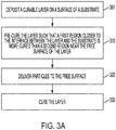
- FIG. 3A is a flow diagram illustrating a method of forming an article in accordance with some embodiments.
- a liquid curable layer is deposited 301 on a substrate.
- the curable layer is pre-cured 310 such that a first region closer to the free surface of the layer is less cured than a second region closer to the interface between the layer and the substrate.
- Particles are delivered 320 to the free surface after pre-curing the layer and the particle-laden layer is cured 330.
- particles are delivered to the free surface of the curable layer before and after the pre-curing step 310.
- the particles delivered before the pre-curing step 310 may be the same type as the particles delivered after the pre-curing step 310 in some embodiments.
- the particles delivered before the pre-curing step 310 may be a different type of particles than the particles delivered after the pre-curing step 310.
- the particles delivered before the pre-curing step 310 may be distributed in the layer in various ways, e.g., may be uniformly distributed or may be disposed in a band.
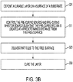
- FIG. 3B is a flow diagram illustrating a method of forming an article that includes a section such as sections 201 and 202 of FIG. 2 in which the particles 299 extend to a predetermined depth in the layer.
- pre-curing the layer includes controlling 311 the pre-curing initiator and/or the pre-curing inhibitor such that the pre-cured region is a located a predetermined distance from the free surface of the layer and the substrate.
- controlling the pre-curing initiator source may involve modulating the amount of the pre-curing initiator, e.g., modulating the intensity of UV radiation or modulating the concentration of a curing gas, etc.
- Controlling the pre-curing inhibitor source may involve controlling concentration of the curing inhibitor, e.g., by controlling the concentration of O 2 in a surrounding atmosphere by flooding with N 2 .
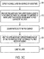
- FIG. 3C is a flow diagram illustrating a method operating system 100 to form an article that includes a section such as sections 201 of FIG. 2 in which the particles 299 are disposed in a band within the layer.
- the method can involve waiting 321 for a predetermined time to let the particles settle from the free surface toward the first region which is more cured.
- the pre-curing device can include a heater configured to heat the layer to reduce viscosity, allowing the particles to settle into the band as illustrated in FIG. 2 .
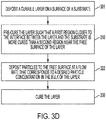
- FIG. 3D is a flow diagram illustrating a method of operating system 100 to form an article that has a predetermined concentration of the particles or a particle concentration gradient in the bulk of the layer as in section 201 of FIG. 2 .
- delivering the particles at the free surface of the layer includes controlling 322 a deposition rate of the particles.
- the deposition rate can be varied, e.g., linearly, to achieve a concentration gradient of the particles as in section 201 of FIG. 2 .
- FIG. 3E is a flow diagram illustrating a method of forming an article that has a predetermined concentration of the particles or a particle concentration gradient at the surface of the layer as in section 202 of FIG. 2 .
- depositing the particles at the free surface of the layer includes controlling 323 a deposition rate of the particles to achieve the desired concentration of particles having at least a portion extending above the layer surface.
- the deposition rate of the particles can be varied to achieve a concentration gradient or pattern of the particles at the surface and/or in the bulk.
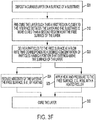
- FIG. 3F is a flow diagram illustrating a method of forming an article in which particles are aligned at the surface and/or depressed into the surface of the layer as in section 203 of FIG. 2 .
- depositing the particles at the free surface of the layer includes controlling 323 a deposition rate of the particles to achieve the desired concentration of particles having at least a portion extending above the layer surface.
- the viscosity of the layer may be reduced 324, e.g., by heating the layer. Reducing the viscosity causes the particles to sink further into the layer. When the particles are elongated as shown, reducing the viscosity can cause the particles to become more aligned near the surface.
- the particles may be subjected to heat and pressure 325, e.g., by a heated roller. Applying heat and/or pressure to the surface of promote alignment and/or settling of the particles in the layer to achieve a desired surface characteristic of the layer.
- FIG. 3G is a flow diagram illustrating a method of forming an article in which the particles are laterally or longitudinally patterned in the layer as in section 204 of FIG. 2 .
- pre-curing the layer includes directing 311 a curing initiator and/or a curing inhibitor towards the layer.
- One or both of the pre-curing initiator and/or the pre-cure inhibitor interacts 312 with a patterning device to form a lateral and/or longitudinal pattern of more cured and less cured regions as illustrated by sections 204a and 204b of FIG. 2 .
- the pre-curing initiator patterning device may comprise a shadow mask, a movable shutter and/or other types of patterning devices such as a liquid crystal device, a digital micromirror device (DMD), a grating light valve (GLV), an acousto-optic modulator (AOM), and/or a polygon mirror raster output scanner (ROS).
- the pre-curing initiator patterning device may comprise an array of pre-curing initiator sources and a controller configured to modulate the intensity of each of the pre-curing initiator sources to produce a spatial pattern of the curing initiator.
- the particles are deposited in the layer and the depth of the particles in the layer is patterned according to the pattern of the more cured regions and the less cured regions.
- the system may include a pre-curing inhibitor patterning device configured to provide a spatial pattern of the curing inhibitor.
- FIG. 3H is a flow diagram illustrating a method of forming an article in which one or more additional layers are formed over a surface of the layer as depicted in section 205 of FIG. 2 .
- one or more layers may be deposited 331 over the surface of the layer.
- the one or more additional layers may be selected to impart certain optical characteristics to the layer, e.g., such as a light scattering layer or specular layer.
- the patterning device may comprise a shadow mask, a movable shutter or other types of patterning devices such as a liquid crystal device, a digital micromirror device (DMD), a grating light valve (GLV), an acousto-optic modulator (AOM), and/or a raster output scanner (ROS).
- a liquid crystal device such as a digital micromirror device (DMD), a grating light valve (GLV), an acousto-optic modulator (AOM), and/or a raster output scanner (ROS).
- DMD digital micromirror device
- GLV grating light valve
- AOM acousto-optic modulator
- ROS raster output scanner
- FIGS. 4 through 11 are block diagrams illustrating various optional configurations of the pre-curing device 140 and/or particle deposition device 160 of system 100.
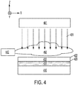
- FIG. 4 shows a pre-curing initiator source 441 located at the free surface side of the layer 420 disposed on substrate 410.
- the pre-curing initiator source 441 is delivering a curing initiator 491 toward the free surface 422.
- the pre-curing initiator source 421 is a UV radiation source, but other types of pre-curing initiator sources can alternatively be used such as a heat source that delivers heat energy, an electron beam source that delivers e-beam curing energy, or a gas source that delivers a curing gas to the layer 420.
- FIG. 4 shows a pre-curing initiator source 441 located at the free surface side of the layer 420 disposed on substrate 410.
- the pre-curing initiator source 441 is delivering a curing initiator 491 toward the free surface 422.
- FIG. 4 depicts a pre-curing inhibitor source 442 positioned to deliver a curing inhibitor gas 492, such as O 2 , toward the free surface 422.
- a curing inhibitor gas 492, such as O 2 a curing inhibitor gas 492, such as O 2 .
- the presence of the curing inhibitor 492 at the free surface 422 inhibits curing in the region 432 near the free surface 422. Deeper in the layer 420, in region 431, the effect of the curing inhibitor 492 is decreased such that the curing initiator 491 overcomes the effect of the curing inhibitor 492 to cure region 431.
- the amount of the curing initiator 491 and/or the amount of the curing inhibitor 492 can be controlled by the controller (not shown in FIG. 4 but previously discussed with reference to FIG. 1 ) to control the relative thicknesses of the first (more cured) region 431 and the second (less cured) region 432 of the layer 420.
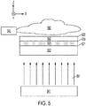
- FIG. 5 illustrates a pre-curing initiator source 541 positioned proximate to the substrate 510.
- the substrate 510 is configured to allow the curing initiator 591 to pass through the substrate 510 with minimal or a sufficiently small amount of attenuation to allow some pre-curing to occur at the interface 521 between the substrate 510 and the layer 520.
- the pre-curing inhibitor source 542 is positioned to deliver a curing inhibitor gas 592 to the free surface 522. The presence of the curing inhibitor 592 at the free surface 522 inhibits curing in the region 532 near the free surface. Deeper in the layer 520, in region 531, the effect of the curing inhibitor 592 is decreased.
- the curing initiator 591 overcomes the effect of the curing inhibitor 592 to cure region 531.
- the amount of the curing initiator 591 e.g., the intensity of UV radiation, and/or the amount of the curing inhibitor 592, e.g., the concentration of curing inhibitor gas, can be controlled by the controller (not shown in FIG. 5 but previously discussed with reference to FIG. 1 ) to control the relative thicknesses of the more cured region 531 and the less cured region 532 of the layer 520.
- UV radiation curing energy is transmitted through a UV transparent substrate into an optically thick curable layer.
- the intensity of UV radiation falls off with distance along the z axis approaching the free surface 522 while the concentration of the inhibitor increases approaching the free surface 522.
- the use of a UV transparent substrate permits a different level of control compared with the configuration in which both the UV radiation and the inhibitor are delivered to the free surface such that both the UV and the inhibitor concentration are decreasing.
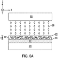
- FIG. 6A illustrates the particle deposition device 660 in the process of depositing particles 699 at the free surface 622 of the layer 620 disposed on substrate 610 after the layer 620 has been pre-cured as discussed in connection with FIGS. 4 or 5 .
- the second (less cured) region 632 is sufficiently uncured so that it allows the particles to embed into the less cured region.
- the first (more cured) region 631 is sufficiently cured to prevent the particles from sinking below a depth, d, from the free surface 622 of the layer 620.
- the concentration of the particles 699 in the less cured region 631 can be controlled by controlling the flow rate of the particles 699 from the particle deposition device 660.
- the particle deposition device 660 may be configured to deposit particles 699 until portions of some of the particles 699 extend above the free surface 622.
- the more cured 731 and less cured 732 regions can be patterned laterally and/or longitudinally, allowing the depth of the particles to vary across the layer 720 laterally and/or longitudinally.
- Some implementations involve the use of one or more masks that mask one or both of the curing initiator and the curing inhibitor.
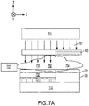
- FIG. 7A is a block diagram that illustrates the use of a mask 743 to block pre-curing initiator 791.
- FIG. 7A depicts a pre-curing inhibitor source 742 positioned to deliver a curing inhibitor 792 to the free surface 722.
- the pre-curing initiator source 741 is proximate to the free surface 722 of the layer 720 and provides a curing initiator 791 that is also directed toward the free surface 722.
- Mask 743 which may be a photolithographic mask, a shadow mask, or any other type of mask, blocks or attenuates curing initiator 791 directed toward the free surface 722 in area 734 and substantially passes curing initiator 791 to the free surface 722 in area 733.
- the presence of the curing inhibitor 792 at the free surface 722 inhibits curing in the region 732 near the free surface 722. Deeper in the layer 720, in region 731, the effect of the curing inhibitor 792 is decreased such that the curing initiator 791 overcomes the effect of the curing inhibitor 792 to cure region 731 in area 734.
- the amount of the curing initiator e.g., intensity of the UV radiation energy 791
- the amount of the curing inhibitor e.g., flow rate of curing inhibitor gas 792
- the controller can be adjusted by the controller to control the relative thicknesses of the more cured region 731 and the less cured region 732 of the layer 720 in area 734.
- the curing initiator 791 is blocked such that area 734 remains uncured through the depth of the layer 720.
- FIG. 7B illustrates a configuration in which the substrate 710 is substantially transparent to the curing initiator 791.
- the pre-curing initiator source 741 is located proximate the substrate 710 and mask 743 is disposed between the substrate 710 and the pre-curing initiator source 741.
- mask 743 blocks or attenuates curing initiator 791 from reaching the layer 720.
- the mask 743 passes curing initiator 791 to the substrate 710.
- the substrate 710 transmits the curing initiator 791 to the interface 721 and into the layer 720.
- the presence of the curing inhibitor 792 at the free surface 722 inhibits curing in the region 732 near the free surface 722. Deeper in the layer 720, in region 731, the effect of the curing inhibitor 792 is decreased such that the curing initiator 791 overcomes the effect of the curing inhibitor 792 to cure region 731 in area 734.
- the amount of the curing initiator e.g., the intensity of the UV radiation energy 791 and/or the amount of the curing inhibitor, e.g., the flow rate of curing inhibitor gas 792, can be adjusted by the controller to control the relative thicknesses of the more cured region 731 and the less cured region 732 of the layer 720 in area 733.
- the curing initiator 791 is blocked from reaching the layer 720, and, as a result area 734 remains uncured through the depth of the layer 720.
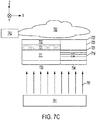
- FIG. 7C illustrates a configuration in which the substrate 710 itself forms a mask.
- substrate 710 includes a first section 711 at a first longitudinal position that is substantially transparent to the curing initiator 791 and a second section 712 at a second longitudinal position that blocks the curing initiator 791.
- the pre-curing initiator source 741 is located proximate the substrate 710.
- substrate section 712 blocks or attenuates curing initiator 791 from reaching the layer 720.
- substrate section 711 passes curing initiator 791 to the interface 721 and into the layer 720.
- the presence of the curing inhibitor 792 at the free surface 722 inhibits curing in the region 732 near the free surface 722. Deeper in the layer 720, in region 731, the effect of the curing inhibitor 792 is decreased such that the curing initiator 791 overcomes the effect of the curing inhibitor 792 to cure region 731 in area 733.
- the amount of the curing initiator e.g., the intensity of the UV radiation 791, and/or the amount of the curing inhibitor, e.g., flow rate of curing inhibitor gas 792, can be adjusted by the controller to control the relative thicknesses of the more cured region 731 and the less cured region 732 of the layer 720 in area 733.
- the curing initiator 791 is blocked from reaching the layer 720, and, as a result area 734 remains uncured through the depth of the layer 720.
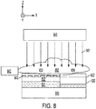
- FIG. 8 depicts a pre-curing inhibitor source 842 positioned to deliver a curing inhibitor 892 to the free surface 822 of layer 820 disposed on substrate 810.
- the pre-curing initiator source 841 is proximate to the free surface 822 of the layer 820 and provides a curing initiator 891 that is also directed toward the free surface 822.
- Mask 843 blocks or attenuates curing inhibitor 892 from reaching the free surface 822 in area 833 and passes the curing inhibitor 892 to the free surface 822 in area 834 without restriction.
- mask 843 is configured to permit the curing initiator 891 to pass through the mask 843.
- the mask 843 at least partially blocks the curing initiator 891, but the curing initiator 891 broadens from region 834 out to permit curing of the layer 831 in region 833.
- the curing initiator 891 may broaden out sufficiently to provide for uniform curing of the layer 831 in some implementations.
- the restricted amount of curing inhibitor 892 that reaches the free surface 822 allows more curing to occur in the region 833.
- the presence of unrestricted curing inhibitor 892 results in less curing in region 834.
- the more cured region 831 in area 833 is thicker along the depth axis when compared to the thickness of the more cured region 831 in area 834.
- the depth of the more cured region 831 measured from the free surface is 822 smaller in area 833 when compared to the depth of the more cured region 831 measured from the free surface 822 in area 834.
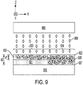
- FIG. 9 illustrates the particle deposition device 960 in the process of depositing particles 999 at the free surface 922 of the layer 920 disposed on substrate 910 after the layer 920 has been pre-cured and patterned as discussed in connection with FIGS. 7A through 8 .
- the less cured region 932 is sufficiently uncured so that it allows the particles to embed into the less material of layer 920.
- the pattern of the more cured region 931 prevents the particles 999 from sinking below a depth, d1, from the free surface 922 of the layer 920 in area 933 and from sinking below a depth, d2, from the free surface 922 in area 934, where d1 ⁇ d2.
- the depth d2 may extend substantially to the interface 921 between the layer 920 and the substrate 901.
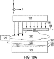
- FIGS. 10A through 11 illustrate system implementations which allow for more complex lateral and/or longitudinal patterning of the more cured and less cured regions 1031, 1131, 1032, 1132 of the layer 1020, 1120.
- patterning of the more cured region 1031 is accomplished using a shutter 1043 that can be moved laterally and/or longitudinally relative to the layer 1020, e.g., along the direction indicated by arrow 1098.
- the pre-curing inhibitor source 1042 is arranged to deliver the pre-curing inhibitor 1092 to the free surface 1022 of the layer 1020 disposed on substrate 1010.
- the pre-curing initiator source 1041 is located on the free surface side of the layer 1020 and directs a pre-curing initiator 1091 toward the free surface 1022.
- the moveable shutter 1043 blocks or attenuates the pre-curing initiator and moves along the direction 1098.
- the shutter 1043 can be moved to provide a variety of patterns in the more cured and less cured regions 1031, 1032, including the gradient pattern shown.
- the linear gradient pattern shown can be achieved when the shutter 1043 is moved with constant velocity along the direction 1098. With constant velocity, the dwell time of the shutter 1043 is longer with respect to some areas of the free surface 1022, preventing the pre-curing initiator 1091 from reaching the free surface 1022 for a longer time period in these areas relative to other areas in which the dwell time of the shutter is shorter.
- the distance, d, of the more cured region 1031 from the free surface 1022 is a function of the time that the shutter 1043 blocks the pre-curing initiator 1091.
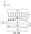
- patterning of the more cured region 1031 is accomplished using a patterned mask 1044.
- the mask 1044 blocks or attenuates more of the pre-curing initiator in some areas relative to other areas resulting in a variable depth of the more cured region 1031.
- the mask 1044 can be designed to provide a variety of patterns in the more cured and less cured regions 1031, 1032 including the gradient pattern shown.
- the pre-curing initiator 1091 is optical radiation
- the mask can be a device 1044 capable spatially patterning the intensity of the pre-curing initiator 1091 in one or two dimensions.
- Suitable devices for this implementation include, for example, a liquid crystal device, a digital micromirror device (DMD), a grating light valve (GLV), an acousto-optic modulator (AOM), and/or a raster output scanner (ROS).
- DMD digital micromirror device
- GLV grating light valve
- AOM acousto-optic modulator
- ROS raster output scanner
- FIG. 11 illustrates the particle deposition device 1160 in the process of depositing particles 1199 at the free surface 1122 of the layer 1120 after the layer 1120 has been pre-cured and patterned as discussed in connection with FIGS. 10A and 10B .
- the less cured region 1132 is sufficiently uncured so that it allows the particles to embed into the less curable material of layer 1120.
- the pattern of the more and less cured regions 1131, 1132 prevents the particles 1199 from sinking below a depth, d, from the free surface 1122 of the layer 1120 where d varies linearly with x in this embodiment.
- the concentration of the particles 1199 in the less cured region 1132 can be controlled by controlling the deposition rate of the particles. For example, in some embodiments, the concentration of the particles 1199 may be substantially constant even though d varies linearly with position.
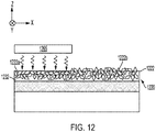
- the system 100 may include a post particle delivery processing device 165 to process the layer after the particles are deposited and before the layer is completely cured.
- post particle delivery processing can involve decreasing the viscosity of the less cured region 1232 so that the particles 1299 settle further into the less cured region 1232.
- elongated particles 1299 may reorient or align such that their major axes lie generally in the plane of the layer 1220.
- decreasing the viscosity may be implemented using a heater 1265 that directs heat toward the free surface 1222 of the layer 1220 as illustrated in FIG. 12 .
- the surface treatment using the heater 1265 can be patterned such that some areas 1222a of the free surface 1222 are heat treated and other areas 1222b are not.
- Post particle delivery processing can involve applying both heat and pressure to the free surface.
- FIG. 13 shows a heated roller 1365 that applies both heat and pressure to the free surface 1322 after the particles 1399 have been deposited.
- the heat and pressure from the roller 1365 depresses the particles 1399 into the less cured region 1332 and may result in alignment of elongated particles 1399. Depressing and aligning the particle in the layer can reduce surface roughness.
- he heated roller 1365 can be applied across substantially the entire free surface 1322.
- the heated roller 1365 can be applied only to selected areas of the free surface 1322 so that only some areas of the free surface 1322 are heat and pressure treated.
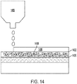
- Post -cure processing may be applied to the free surface after the curing step that follows particle delivery.
- Post cure processing may include surface treatments of the cured free surface and/or deposition of additional layers, for example.
- FIG. 14 illustrates post-cure processing by a deposition device 1485 that is depositing an additional layer 1486 on the free surface 1422 of the layer 1420 after the particles 1499 have been deposited and the layer 1420 has been cured.
- Approaches discussed herein involve an inkjet/powder jet printing process which enables separate control of lateral resolution and particle loading by ink jetting patterns of UV ink followed by powder application and finally a curing process.
- the disclosed approaches provide the ability to control the depth, thickness, and concentration of particulates in the layer.
- pre-curing of the UV curable ink in the presence of a controlled O 2 concentration and UV light intensity enables precise control of the particulates within the UV curable ink. This control enables the chemical, optical, and mechanical properties of the printed patterns to be controlled.
- the systems and methods discussed herein help to insure high quality mechanical properties of films.
- the disclosed approaches preserve the utility of powder inkjet over other methods including large particle densities and compatibility with a wide range of particles with high resolution.
- controllers described above may be implemented using circuitry and/or software modules that interact to provide particular results.
- One of skill in the computing arts can readily implement such described functionality, either at a modular level or as a whole, using knowledge generally known in the art.
- the flowcharts illustrated herein may be used to create computer-readable instructions/code for execution by a processor. Such instructions may be stored on a computer-readable medium and transferred to the processor for execution as is known in the art.
- the structures and procedures shown above are only a representative example of embodiments that can be used to facilitate inkjet ejector diagnostics as described above.
Landscapes
- Chemical & Material Sciences (AREA)
- Engineering & Computer Science (AREA)
- Materials Engineering (AREA)
- Manufacturing & Machinery (AREA)
- Physics & Mathematics (AREA)
- Life Sciences & Earth Sciences (AREA)
- Wood Science & Technology (AREA)
- Organic Chemistry (AREA)
- Optics & Photonics (AREA)
- Mechanical Engineering (AREA)
- Chemical Kinetics & Catalysis (AREA)
- Health & Medical Sciences (AREA)
- Electromagnetism (AREA)
- General Health & Medical Sciences (AREA)
- Toxicology (AREA)
- Coating Apparatus (AREA)
- Application Of Or Painting With Fluid Materials (AREA)
- Ink Jet (AREA)
Applications Claiming Priority (1)
| Application Number | Priority Date | Filing Date | Title |
|---|---|---|---|
| US16/210,656 US10814649B2 (en) | 2018-12-05 | 2018-12-05 | Control of particle layer depth and thickness during powder printing |
Publications (2)
| Publication Number | Publication Date |
|---|---|
| EP3663094A1 EP3663094A1 (en) | 2020-06-10 |
| EP3663094B1 true EP3663094B1 (en) | 2021-09-22 |
Family
ID=68806582
Family Applications (1)
| Application Number | Title | Priority Date | Filing Date |
|---|---|---|---|
| EP19213697.6A Not-in-force EP3663094B1 (en) | 2018-12-05 | 2019-12-04 | Control of particle layer depth and thickness during powder printing |
Country Status (3)
| Country | Link |
|---|---|
| US (1) | US10814649B2 (enExample) |
| EP (1) | EP3663094B1 (enExample) |
| JP (1) | JP7488433B2 (enExample) |
Families Citing this family (4)
| Publication number | Priority date | Publication date | Assignee | Title |
|---|---|---|---|---|
| US11383545B2 (en) * | 2019-05-01 | 2022-07-12 | Xerox Corporation | Apparatus and method for deposting an overcoat on an image on a substrate |
| WO2021100701A1 (ja) * | 2019-11-20 | 2021-05-27 | 富士フイルム株式会社 | 加飾部材製造装置及び加飾部材製造方法 |
| JP2023512105A (ja) * | 2020-02-03 | 2023-03-23 | スリーエム イノベイティブ プロパティズ カンパニー | 積層造形によって表面改質3次元物品を製造するためのプロセス、改質された表面を有する3次元物品及びその使用 |
| LU102233B1 (en) * | 2020-11-23 | 2022-05-23 | Tarkett Gdl Sa | Digital Embossing of decorative surface coverings |
Family Cites Families (15)
| Publication number | Priority date | Publication date | Assignee | Title |
|---|---|---|---|---|
| NL290912A (enExample) | 1962-11-15 | |||
| US5387380A (en) | 1989-12-08 | 1995-02-07 | Massachusetts Institute Of Technology | Three-dimensional printing techniques |
| JP3177128B2 (ja) | 1994-08-10 | 2001-06-18 | キヤノン株式会社 | 吐出部、吐出部を用いたインクジェットカートリッジ、インクジェットプリント装置および方法 |
| US6502912B1 (en) | 1996-09-23 | 2003-01-07 | Pitney Bowes Inc. | Method of printing postage indicia using ink jet technology |
| US20040101619A1 (en) | 2000-03-30 | 2004-05-27 | Carlo Camorani | Object decoration |
| US6746114B2 (en) | 2001-05-10 | 2004-06-08 | Canon Kabushiki Kaisha | Ink set, process for forming colored portion and ink-jet recording apparatus |
| JP2005288286A (ja) * | 2004-03-31 | 2005-10-20 | Nippon Paper Industries Co Ltd | ハードコートフィルムの製造方法及びハードコートフィルム |
| ATE468373T1 (de) | 2005-09-12 | 2010-06-15 | Electronics For Imaging Inc | Metallic-tintenstrahldrucksystem für graphische anwendungen |
| US9346303B2 (en) * | 2009-12-22 | 2016-05-24 | Scodix Ltd | System and method to apply topping materials to print products |
| JP4846867B2 (ja) * | 2010-03-31 | 2011-12-28 | 三菱レイヨン株式会社 | 積層体及びその製造方法 |
| US9527307B2 (en) * | 2010-12-15 | 2016-12-27 | Electronics For Imaging, Inc. | Oxygen inhibition for print-head reliability |
| JP6112891B2 (ja) * | 2013-02-08 | 2017-04-12 | デクセリアルズ株式会社 | 粘着テープ用樹脂組成物、粘着テープ及び粘着テープの製造方法 |
| AU2015240954B2 (en) * | 2014-03-31 | 2018-06-28 | Avery Dennison Corporation | Printable adhesive and label assembly |
| JP6693870B2 (ja) | 2014-05-16 | 2020-05-13 | 株式会社ミマキエンジニアリング | インクジェット印刷方法 |
| US10738204B2 (en) * | 2018-04-20 | 2020-08-11 | Xerox Corporation | Printing process for preparing controlled scattering effects |
-
2018
- 2018-12-05 US US16/210,656 patent/US10814649B2/en active Active
-
2019
- 2019-11-12 JP JP2019204332A patent/JP7488433B2/ja active Active
- 2019-12-04 EP EP19213697.6A patent/EP3663094B1/en not_active Not-in-force
Also Published As
| Publication number | Publication date |
|---|---|
| US20200180328A1 (en) | 2020-06-11 |
| US10814649B2 (en) | 2020-10-27 |
| JP7488433B2 (ja) | 2024-05-22 |
| EP3663094A1 (en) | 2020-06-10 |
| JP2020089874A (ja) | 2020-06-11 |
Similar Documents
| Publication | Publication Date | Title |
|---|---|---|
| EP3663094B1 (en) | Control of particle layer depth and thickness during powder printing | |
| RU2481959C2 (ru) | Способ и устройство для нанесения полимерных покрытий | |
| US12194492B2 (en) | Digital printing apparatus and a digital method for producing a structured surface | |
| RU2412814C2 (ru) | Способ структурирования поверхности прессованного листа или бесконечной ленты | |
| US6846073B2 (en) | Ink jet printer and its thick film printing method | |
| CN104768771B (zh) | 用于装饰面板的方法和设备 | |
| JP2020172110A (ja) | フォイルを適用するための方法、適用装置及びプリント装置 | |
| KR102034788B1 (ko) | 잉크젯 프린팅에 의한 중합성 입자 및 거친 코팅의 제조 | |
| JP2020527476A (ja) | オブジェクトの装飾のための装置および方法 | |
| EP3331653B1 (en) | Spot gloss and gloss control in an inkjet printing system | |
| GB2422344A (en) | Rapid prototyping using infrared sintering | |
| EP3077121B1 (en) | Method for applying thin coating on large area surface | |
| JP2020089874A5 (enExample) | ||
| US8083307B2 (en) | Method of fabricating three-dimensional structure and method of manufacturing substrate with spacer | |
| JP2013206858A (ja) | 紫外線硬化膜の形成方法及び装置 | |
| JP2010012391A (ja) | 液体吐出装置及び液体パターンの形成方法 | |
| CN102582256A (zh) | 记录装置 | |
| JP5863576B2 (ja) | 金属酸化物表面を備えた平坦化部材を有する、uvゲルインク平坦化および基材上に直接に噴射蒸着する方式のデジタル放射線硬化性ゲルインク印刷のための方法、装置、ならびにシステム | |
| JP6871435B2 (ja) | インクジェット印刷装置 | |
| KR102431725B1 (ko) | 잉크젯 프린팅 시스템 용 자외선 경화장치 | |
| KR20210021315A (ko) | 3차원 물체의 생산을 위한 스테레오리소그래피 방법 및 그 장치 | |
| WO2022224641A1 (ja) | 塗布装置、製造システム、塗布装置の制御方法および塗布装置の調整方法 | |
| KR101912312B1 (ko) | 삼차원 프린터 | |
| JP2022067852A (ja) | 3次元印刷装置および3次元印刷方法 | |
| US20210101344A1 (en) | Additive manufacturing system |
Legal Events
| Date | Code | Title | Description |
|---|---|---|---|
| PUAI | Public reference made under article 153(3) epc to a published international application that has entered the european phase |
Free format text: ORIGINAL CODE: 0009012 |
|
| STAA | Information on the status of an ep patent application or granted ep patent |
Free format text: STATUS: THE APPLICATION HAS BEEN PUBLISHED |
|
| AK | Designated contracting states |
Kind code of ref document: A1 Designated state(s): AL AT BE BG CH CY CZ DE DK EE ES FI FR GB GR HR HU IE IS IT LI LT LU LV MC MK MT NL NO PL PT RO RS SE SI SK SM TR |
|
| AX | Request for extension of the european patent |
Extension state: BA ME |
|
| STAA | Information on the status of an ep patent application or granted ep patent |
Free format text: STATUS: REQUEST FOR EXAMINATION WAS MADE |
|
| 17P | Request for examination filed |
Effective date: 20201210 |
|
| RBV | Designated contracting states (corrected) |
Designated state(s): AL AT BE BG CH CY CZ DE DK EE ES FI FR GB GR HR HU IE IS IT LI LT LU LV MC MK MT NL NO PL PT RO RS SE SI SK SM TR |
|
| GRAP | Despatch of communication of intention to grant a patent |
Free format text: ORIGINAL CODE: EPIDOSNIGR1 |
|
| STAA | Information on the status of an ep patent application or granted ep patent |
Free format text: STATUS: GRANT OF PATENT IS INTENDED |
|
| INTG | Intention to grant announced |
Effective date: 20210421 |
|
| GRAS | Grant fee paid |
Free format text: ORIGINAL CODE: EPIDOSNIGR3 |
|
| GRAA | (expected) grant |
Free format text: ORIGINAL CODE: 0009210 |
|
| STAA | Information on the status of an ep patent application or granted ep patent |
Free format text: STATUS: THE PATENT HAS BEEN GRANTED |
|
| AK | Designated contracting states |
Kind code of ref document: B1 Designated state(s): AL AT BE BG CH CY CZ DE DK EE ES FI FR GB GR HR HU IE IS IT LI LT LU LV MC MK MT NL NO PL PT RO RS SE SI SK SM TR |
|
| REG | Reference to a national code |
Ref country code: GB Ref legal event code: FG4D |
|
| REG | Reference to a national code |
Ref country code: IE Ref legal event code: FG4D |
|
| REG | Reference to a national code |
Ref country code: DE Ref legal event code: R096 Ref document number: 602019007847 Country of ref document: DE |
|
| REG | Reference to a national code |
Ref country code: CH Ref legal event code: EP Ref country code: AT Ref legal event code: REF Ref document number: 1432021 Country of ref document: AT Kind code of ref document: T Effective date: 20211015 |
|
| REG | Reference to a national code |
Ref country code: LT Ref legal event code: MG9D |
|
| REG | Reference to a national code |
Ref country code: NL Ref legal event code: MP Effective date: 20210922 |
|
| PG25 | Lapsed in a contracting state [announced via postgrant information from national office to epo] |
Ref country code: HR Free format text: LAPSE BECAUSE OF FAILURE TO SUBMIT A TRANSLATION OF THE DESCRIPTION OR TO PAY THE FEE WITHIN THE PRESCRIBED TIME-LIMIT Effective date: 20210922 Ref country code: FI Free format text: LAPSE BECAUSE OF FAILURE TO SUBMIT A TRANSLATION OF THE DESCRIPTION OR TO PAY THE FEE WITHIN THE PRESCRIBED TIME-LIMIT Effective date: 20210922 Ref country code: NO Free format text: LAPSE BECAUSE OF FAILURE TO SUBMIT A TRANSLATION OF THE DESCRIPTION OR TO PAY THE FEE WITHIN THE PRESCRIBED TIME-LIMIT Effective date: 20211222 Ref country code: LT Free format text: LAPSE BECAUSE OF FAILURE TO SUBMIT A TRANSLATION OF THE DESCRIPTION OR TO PAY THE FEE WITHIN THE PRESCRIBED TIME-LIMIT Effective date: 20210922 Ref country code: BG Free format text: LAPSE BECAUSE OF FAILURE TO SUBMIT A TRANSLATION OF THE DESCRIPTION OR TO PAY THE FEE WITHIN THE PRESCRIBED TIME-LIMIT Effective date: 20211222 Ref country code: RS Free format text: LAPSE BECAUSE OF FAILURE TO SUBMIT A TRANSLATION OF THE DESCRIPTION OR TO PAY THE FEE WITHIN THE PRESCRIBED TIME-LIMIT Effective date: 20210922 Ref country code: SE Free format text: LAPSE BECAUSE OF FAILURE TO SUBMIT A TRANSLATION OF THE DESCRIPTION OR TO PAY THE FEE WITHIN THE PRESCRIBED TIME-LIMIT Effective date: 20210922 |
|
| REG | Reference to a national code |
Ref country code: AT Ref legal event code: MK05 Ref document number: 1432021 Country of ref document: AT Kind code of ref document: T Effective date: 20210922 |
|
| PG25 | Lapsed in a contracting state [announced via postgrant information from national office to epo] |
Ref country code: LV Free format text: LAPSE BECAUSE OF FAILURE TO SUBMIT A TRANSLATION OF THE DESCRIPTION OR TO PAY THE FEE WITHIN THE PRESCRIBED TIME-LIMIT Effective date: 20210922 Ref country code: GR Free format text: LAPSE BECAUSE OF FAILURE TO SUBMIT A TRANSLATION OF THE DESCRIPTION OR TO PAY THE FEE WITHIN THE PRESCRIBED TIME-LIMIT Effective date: 20211223 |
|
| PG25 | Lapsed in a contracting state [announced via postgrant information from national office to epo] |
Ref country code: AT Free format text: LAPSE BECAUSE OF FAILURE TO SUBMIT A TRANSLATION OF THE DESCRIPTION OR TO PAY THE FEE WITHIN THE PRESCRIBED TIME-LIMIT Effective date: 20210922 |
|
| PG25 | Lapsed in a contracting state [announced via postgrant information from national office to epo] |
Ref country code: IS Free format text: LAPSE BECAUSE OF FAILURE TO SUBMIT A TRANSLATION OF THE DESCRIPTION OR TO PAY THE FEE WITHIN THE PRESCRIBED TIME-LIMIT Effective date: 20220122 Ref country code: SK Free format text: LAPSE BECAUSE OF FAILURE TO SUBMIT A TRANSLATION OF THE DESCRIPTION OR TO PAY THE FEE WITHIN THE PRESCRIBED TIME-LIMIT Effective date: 20210922 Ref country code: RO Free format text: LAPSE BECAUSE OF FAILURE TO SUBMIT A TRANSLATION OF THE DESCRIPTION OR TO PAY THE FEE WITHIN THE PRESCRIBED TIME-LIMIT Effective date: 20210922 Ref country code: PT Free format text: LAPSE BECAUSE OF FAILURE TO SUBMIT A TRANSLATION OF THE DESCRIPTION OR TO PAY THE FEE WITHIN THE PRESCRIBED TIME-LIMIT Effective date: 20220124 Ref country code: PL Free format text: LAPSE BECAUSE OF FAILURE TO SUBMIT A TRANSLATION OF THE DESCRIPTION OR TO PAY THE FEE WITHIN THE PRESCRIBED TIME-LIMIT Effective date: 20210922 Ref country code: NL Free format text: LAPSE BECAUSE OF FAILURE TO SUBMIT A TRANSLATION OF THE DESCRIPTION OR TO PAY THE FEE WITHIN THE PRESCRIBED TIME-LIMIT Effective date: 20210922 Ref country code: ES Free format text: LAPSE BECAUSE OF FAILURE TO SUBMIT A TRANSLATION OF THE DESCRIPTION OR TO PAY THE FEE WITHIN THE PRESCRIBED TIME-LIMIT Effective date: 20210922 Ref country code: EE Free format text: LAPSE BECAUSE OF FAILURE TO SUBMIT A TRANSLATION OF THE DESCRIPTION OR TO PAY THE FEE WITHIN THE PRESCRIBED TIME-LIMIT Effective date: 20210922 Ref country code: CZ Free format text: LAPSE BECAUSE OF FAILURE TO SUBMIT A TRANSLATION OF THE DESCRIPTION OR TO PAY THE FEE WITHIN THE PRESCRIBED TIME-LIMIT Effective date: 20210922 Ref country code: AL Free format text: LAPSE BECAUSE OF FAILURE TO SUBMIT A TRANSLATION OF THE DESCRIPTION OR TO PAY THE FEE WITHIN THE PRESCRIBED TIME-LIMIT Effective date: 20210922 |
|
| REG | Reference to a national code |
Ref country code: DE Ref legal event code: R097 Ref document number: 602019007847 Country of ref document: DE |
|
| PG25 | Lapsed in a contracting state [announced via postgrant information from national office to epo] |
Ref country code: MC Free format text: LAPSE BECAUSE OF FAILURE TO SUBMIT A TRANSLATION OF THE DESCRIPTION OR TO PAY THE FEE WITHIN THE PRESCRIBED TIME-LIMIT Effective date: 20210922 Ref country code: DK Free format text: LAPSE BECAUSE OF FAILURE TO SUBMIT A TRANSLATION OF THE DESCRIPTION OR TO PAY THE FEE WITHIN THE PRESCRIBED TIME-LIMIT Effective date: 20210922 |
|
| PLBE | No opposition filed within time limit |
Free format text: ORIGINAL CODE: 0009261 |
|
| STAA | Information on the status of an ep patent application or granted ep patent |
Free format text: STATUS: NO OPPOSITION FILED WITHIN TIME LIMIT |
|
| 26N | No opposition filed |
Effective date: 20220623 |
|
| REG | Reference to a national code |
Ref country code: BE Ref legal event code: MM Effective date: 20211231 |
|
| PG25 | Lapsed in a contracting state [announced via postgrant information from national office to epo] |
Ref country code: LU Free format text: LAPSE BECAUSE OF NON-PAYMENT OF DUE FEES Effective date: 20211204 Ref country code: IE Free format text: LAPSE BECAUSE OF NON-PAYMENT OF DUE FEES Effective date: 20211204 |
|
| PG25 | Lapsed in a contracting state [announced via postgrant information from national office to epo] |
Ref country code: SI Free format text: LAPSE BECAUSE OF FAILURE TO SUBMIT A TRANSLATION OF THE DESCRIPTION OR TO PAY THE FEE WITHIN THE PRESCRIBED TIME-LIMIT Effective date: 20210922 Ref country code: BE Free format text: LAPSE BECAUSE OF NON-PAYMENT OF DUE FEES Effective date: 20211231 |
|
| PG25 | Lapsed in a contracting state [announced via postgrant information from national office to epo] |
Ref country code: IT Free format text: LAPSE BECAUSE OF FAILURE TO SUBMIT A TRANSLATION OF THE DESCRIPTION OR TO PAY THE FEE WITHIN THE PRESCRIBED TIME-LIMIT Effective date: 20210922 |
|
| PG25 | Lapsed in a contracting state [announced via postgrant information from national office to epo] |
Ref country code: CY Free format text: LAPSE BECAUSE OF FAILURE TO SUBMIT A TRANSLATION OF THE DESCRIPTION OR TO PAY THE FEE WITHIN THE PRESCRIBED TIME-LIMIT Effective date: 20210922 |
|
| PG25 | Lapsed in a contracting state [announced via postgrant information from national office to epo] |
Ref country code: SM Free format text: LAPSE BECAUSE OF FAILURE TO SUBMIT A TRANSLATION OF THE DESCRIPTION OR TO PAY THE FEE WITHIN THE PRESCRIBED TIME-LIMIT Effective date: 20210922 Ref country code: HU Free format text: LAPSE BECAUSE OF FAILURE TO SUBMIT A TRANSLATION OF THE DESCRIPTION OR TO PAY THE FEE WITHIN THE PRESCRIBED TIME-LIMIT; INVALID AB INITIO Effective date: 20191204 |
|
| REG | Reference to a national code |
Ref country code: CH Ref legal event code: PL |
|
| PG25 | Lapsed in a contracting state [announced via postgrant information from national office to epo] |
Ref country code: LI Free format text: LAPSE BECAUSE OF NON-PAYMENT OF DUE FEES Effective date: 20221231 Ref country code: CH Free format text: LAPSE BECAUSE OF NON-PAYMENT OF DUE FEES Effective date: 20221231 |
|
| PGFP | Annual fee paid to national office [announced via postgrant information from national office to epo] |
Ref country code: GB Payment date: 20231124 Year of fee payment: 5 |
|
| PGFP | Annual fee paid to national office [announced via postgrant information from national office to epo] |
Ref country code: FR Payment date: 20231122 Year of fee payment: 5 Ref country code: DE Payment date: 20231121 Year of fee payment: 5 |
|
| PG25 | Lapsed in a contracting state [announced via postgrant information from national office to epo] |
Ref country code: MK Free format text: LAPSE BECAUSE OF FAILURE TO SUBMIT A TRANSLATION OF THE DESCRIPTION OR TO PAY THE FEE WITHIN THE PRESCRIBED TIME-LIMIT Effective date: 20210922 |
|
| PG25 | Lapsed in a contracting state [announced via postgrant information from national office to epo] |
Ref country code: MT Free format text: LAPSE BECAUSE OF FAILURE TO SUBMIT A TRANSLATION OF THE DESCRIPTION OR TO PAY THE FEE WITHIN THE PRESCRIBED TIME-LIMIT Effective date: 20210922 |
|
| REG | Reference to a national code |
Ref country code: DE Ref legal event code: R119 Ref document number: 602019007847 Country of ref document: DE |
|
| GBPC | Gb: european patent ceased through non-payment of renewal fee |
Effective date: 20241204 |
|
| PG25 | Lapsed in a contracting state [announced via postgrant information from national office to epo] |
Ref country code: DE Free format text: LAPSE BECAUSE OF NON-PAYMENT OF DUE FEES Effective date: 20250701 |
|
| PG25 | Lapsed in a contracting state [announced via postgrant information from national office to epo] |
Ref country code: GB Free format text: LAPSE BECAUSE OF NON-PAYMENT OF DUE FEES Effective date: 20241204 |
|
| PG25 | Lapsed in a contracting state [announced via postgrant information from national office to epo] |
Ref country code: FR Free format text: LAPSE BECAUSE OF NON-PAYMENT OF DUE FEES Effective date: 20241231 |
|
| PG25 | Lapsed in a contracting state [announced via postgrant information from national office to epo] |
Ref country code: TR Free format text: LAPSE BECAUSE OF FAILURE TO SUBMIT A TRANSLATION OF THE DESCRIPTION OR TO PAY THE FEE WITHIN THE PRESCRIBED TIME-LIMIT Effective date: 20210922 |