EP3663015B1 - Maschine zum herstellen von drahtelementen - Google Patents
Maschine zum herstellen von drahtelementen Download PDFInfo
- Publication number
- EP3663015B1 EP3663015B1 EP19211754.7A EP19211754A EP3663015B1 EP 3663015 B1 EP3663015 B1 EP 3663015B1 EP 19211754 A EP19211754 A EP 19211754A EP 3663015 B1 EP3663015 B1 EP 3663015B1
- Authority
- EP
- European Patent Office
- Prior art keywords
- wire
- wire elements
- bending
- machine according
- designed
- Prior art date
- Legal status (The legal status is an assumption and is not a legal conclusion. Google has not performed a legal analysis and makes no representation as to the accuracy of the status listed.)
- Active
Links
Images
Classifications
-
- B—PERFORMING OPERATIONS; TRANSPORTING
- B21—MECHANICAL METAL-WORKING WITHOUT ESSENTIALLY REMOVING MATERIAL; PUNCHING METAL
- B21F—WORKING OR PROCESSING OF METAL WIRE
- B21F1/00—Bending wire other than coiling; Straightening wire
- B21F1/004—Bending wire other than coiling; Straightening wire by means of press-type tooling
-
- H—ELECTRICITY
- H02—GENERATION; CONVERSION OR DISTRIBUTION OF ELECTRIC POWER
- H02K—DYNAMO-ELECTRIC MACHINES
- H02K15/00—Processes or apparatus specially adapted for manufacturing, assembling, maintaining or repairing of dynamo-electric machines
- H02K15/04—Processes or apparatus specially adapted for manufacturing, assembling, maintaining or repairing of dynamo-electric machines of windings prior to their mounting into the machines
- H02K15/0414—Processes or apparatus specially adapted for manufacturing, assembling, maintaining or repairing of dynamo-electric machines of windings prior to their mounting into the machines the windings consisting of separate elements, e.g. bars, segments or half coils
- H02K15/0421—Processes or apparatus specially adapted for manufacturing, assembling, maintaining or repairing of dynamo-electric machines of windings prior to their mounting into the machines the windings consisting of separate elements, e.g. bars, segments or half coils and consisting of single conductors, e.g. hairpins
Definitions
- the present invention relates to a machine for producing wire elements with two legs running essentially in one plane, the apex of which lies outside the plane of the legs, and a method for operating such a machine.
- Wire elements of this type with two legs that essentially run in one plane and whose apex lies outside the plane of the legs, are also referred to as "hairpin" elements based on similarly shaped hairpins and are used, for example, in the production of stator units for electric motors and generators, whereby due to the With the increasing electrification of motor transport, it is to be expected that the market for such stator units and thus also for the wire elements mentioned will increase significantly in the future.
- the individual wire elements through which current flows during operation of the stator are similar in their dimensions and geometric shapes, but not completely identical. Rather, it is usually the case that several types of wire elements are required for the construction of one of the stated stator units, which in turn are present in different numbers in the finished stator unit and differ slightly in their external dimensions, for example, but are of a similar shape.
- the known from the prior art manufacturing method of such wire elements with a single head has the disadvantage that in order to achieve the necessary flexibility for manufacturing a plurality of slightly different types of wire elements, a complex set-up of the stamping and bending machine after the production of each of the types is necessary, so that usually large quantities of a first type are produced first, followed by large quantities of a second type, etc., which then in turn have to be sorted in a complex manner.
- the sequential production of the individual types of wire elements has the disadvantage that large quantities of the wire elements can be unusable in the event of an error in production or a non-compliance with the tolerance, which in turn is due to the low flexibility of the production device.
- GB 1 496 445 A comprises a machine for producing wire elements with two legs running essentially in one plane, with only one type of wire element being able to be produced at a time and the machine having to be converted when changing over to a different type.
- the object of the present invention is to provide a more efficient, simpler and more reliable machine and a method for operating this machine for producing such wire elements. through which increases the number of cycles during production and the Changeover times can be reduced, and which is characterized by increased flexibility with consistent quality of the wire elements.
- the machine according to the invention for the production of wire elements with two legs running essentially in one plane, the apex of which lies outside the plane of the legs, comprises a feed device for substantially rectilinear wire blanks having a predetermined length, a first bending device adapted to perform a first bending operation on wire blanks fed from the feeder to form planar wire elements having two legs and a crest, a plurality of second bending devices, which respectively a different embossing element, wherein the second bending devices are all arranged to bend the apexes of the planar wire elements out of the plane of the legs, a first transport device arranged to transport the wire elements from the first bending device to one of the plurality of second bending devices transfer, and a controller operatively coupled to the feeder, the first bending device, the second bending devices and the first transport device for controlling them and adapted to do so based on process parameters etern to control the first transport device to transfer the wire elements to a selected one of the second bending devices
- the manufacturing process in the machine for manufacturing wire elements just described is divided into two separate sub-steps and the first bending device first bends straight wire blanks into two-dimensional wire elements with two legs, with only then, in a further bending process, using a stamping element, the Apex of the wire elements is bent out of the leg plane.
- the first bending device can have certain degrees of freedom and process parameters during operation, as a result of which the wire elements it produces can differ, for example in the angle between the two legs or in the case of parallel legs in their spacing.
- the machine according to the invention a large number of different types of wire elements can be produced without intermediate set-up, which significantly reduces the downtime of the machine, in addition to which the simplification and separation of the work steps carried out by the first and the respective second bending device a significantly increased number of cycles can be achieved in the production of the wire elements.
- the wire elements produced by the machine according to the invention can be of different types, it can be advantageous if the machine further comprises a magazine for storing the finished wire elements and a second transport device which is adapted to be controlled by one of the second bending devices Store bent wire elements in the magazine.
- the magazine can include a plurality of shelves, each of which is assigned to one of the second bending devices, the second transport device in this case being set up to place a wire element bent by one of the second bending devices in the shelf assigned to this second bending device to take off
- the second transport device in this case being set up to place a wire element bent by one of the second bending devices in the shelf assigned to this second bending device to take off
- the magazine could also comprise a plurality of shelves, with the second transport device also being operatively coupled to the control device and being operated to deposit the wire elements bent by one of the second bending devices in a shelf determined by the control device.
- the flexibility of the machine according to the invention and the associated magazine is increased even further, since completely free sorting of the finished wire elements in the magazine in the individual shelves is permitted, so that, for example, each individual type of wire element is stored in a single shelf even when several types of wire elements have been coined in the same second bender.
- the magazine thus forms a buffer for finished wire elements
- the machine according to the invention can also comprise a removal device which is set up to remove a predetermined number of wire elements from the plurality of shelves of the magazine, in order to create a set of wire elements to provide.
- a removal device which is set up to remove a predetermined number of wire elements from the plurality of shelves of the magazine, in order to create a set of wire elements to provide. This of course includes the case just described, in which the entire set is already pre-sorted in one of the shelves.
- the first bending device of the machine according to the invention can be set up to bend the wire elements in such a way to bend so that its two legs are substantially parallel to each other.
- This inevitably means that, in addition to the apex of the wire elements, at least two further bends must be present on the wire element produced in this way.
- these two additional bends will be relatively close to the apex in such a way that together with the apex they form a triangle from which the legs then extend in parallel.
- the feed device can also comprise a cutting device which is set up to cut a fed cutting wire into wire blanks of predetermined lengths, the cutting device also preferably being operatively coupled to the controller.
- another parameter of the wire elements finally produced is controlled by the control device of the machine according to the invention, namely the length of the individual blanks and consequently the overall length or the external dimensions of the wire elements finally produced.
- this embodiment has the advantage that an endless wire can be fed to the cutting device, which means simplified handling of the starting materials compared to a device in which wire blanks have to be inserted and transported.
- the feed device can additionally or alternatively comprise a stripping unit which is set up to remove insulation surrounding the wire at least at one end of the wire blanks.
- a stripping unit can be designed for operation both with a continuous wire being fed in and with wire blanks that have already been fed in, and allows the finished wire elements to be removed already in a state in which their ends can be electrically connected or connected.
- the machine according to the invention can comprise at least one control unit which is set up to measure at least one property of the wire blanks and/or the wire elements and to compare it with specified target values, wherein the control unit can preferably also be operatively coupled to the control device.
- the properties of the wire blanks or wire elements to be measured can be, for example, their length or other geometric properties, such as various parameters of their shape, their electrical resistance, the strength of the wire or the like. If it is determined that one of the measured parameters is outside a tolerance range, various measures can be taken, such as sorting out the blank or wire element in question, switching off the machine or the like.
- the present invention relates to a method for operating a machine according to the invention, comprising the steps of feeding essentially rectilinear wire blanks with a predetermined length, bending the wire blanks fed by the feeding device to flat wire elements with two legs and a vertex forming, transferring the wire elements to one of the plurality of second bending devices, and coining the planar wire elements to bend their crests out of the leg plane.
- the wire blanks can be formed in particular from copper or another metallic material with good conductivity and can optionally include insulation.
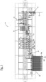
- FIG. 1 shows first a machine according to the invention for the production of wire elements in a plan view, the machine being denoted generally by the reference numeral 10.
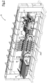
- FIG. 1 the same machine 10 is shown in an oblique side view.
- an endless wire D is fed to it, which is cut into straight wire blanks R by a cutting device 14 forming part of the feed device 12, the length of the wire blanks R being variable according to instructions from a control device, not shown.
- the wire blanks R are further stripped at one or both ends by a stripping unit 16 , the stripping unit 16 also being associated with the feed device 12 . Subsequently, the blanks R cut to size and stripped in this way are subjected to an optical and/or electrical check by a control device 18, in which it is determined whether their geometric and/or electrical parameters lie within a predetermined tolerance range.
- the machine 10 Downstream of the control device 18, the machine 10 comprises a first bending device 20, in which the previously straight blanks R are bent in such a way that they are subsequently in the form of flat wire elements with two legs and an apex, the two legs being parallel to one another in the case shown, although this does not have to be the case in all variants.
- the wire elements bent in this way are in the figures 1 and 2 denoted by the reference E1.
- the first bending device 20 is set up in such a way that certain parameters of the elements E1 can be adjusted, for example the angle of the apex and the distance between the two parallel legs.
- the wire elements E1 bent in this way are then picked up by a first transport device 22, which first rotates the wire elements E1 by 180° and then transports them to a plurality of second bending devices 24a-f arranged one behind the other, each of which has a stamping element 26a-f, with distinguish the individual embossed elements 26a-f from one another.
- each of the wire elements E1 is transported to one of the second bending devices 24a-f and then stamped by the corresponding bending device in such a way that the apex of the element E1 is bent out of the plane of the legs.
- the second bending devices 24a-f there are wire elements E2 with two legs running essentially in one plane, the apex of which lies outside the plane of the legs.
- the elements E2 can differ in several parameters, such as the length of their legs, the angle of their apex and the amount of bending of the vertex out of the plane of the legs, which then determines, for example, the offset of the vertex in relation to the plane of the legs.
- the finished wire elements E2 are then transported by a second transport device 28 to a magazine 30, the one Has a plurality of shelves, of which only three shelves 30a - 30c should be designated.
- the second transport device 28 can be controlled, for example, by the control device (not shown) in such a way that all finished wire elements E2 of the same type, i.e. with the same properties, are placed on the same tray of the magazine 30, for example as in FIG figure 2 to be seen on the first tray 30a.
- the control device can change the control of at least one of the devices controlled by it, i.e. for example the cutting device 14, the first bending device 20 and/or the selection of the second bending device 24a-f, so that a second type of finished wire element E2 is then produced, which can then be stored accordingly in one of the other shelves of the magazine 30, for example the second shelf 30b.
- a removal device (not shown) can also be assigned to the magazine 30, which removes a predetermined number of finished wire elements E2 from various of the shelves of the magazine 30 in order to provide a set of wire elements E2 for further processing.
Landscapes
- Engineering & Computer Science (AREA)
- Mechanical Engineering (AREA)
- Manufacturing & Machinery (AREA)
- Power Engineering (AREA)
- Wire Processing (AREA)
- Surgical Instruments (AREA)
- Wire Bonding (AREA)
Applications Claiming Priority (1)
| Application Number | Priority Date | Filing Date | Title |
|---|---|---|---|
| DE102018221152.3A DE102018221152A1 (de) | 2018-12-06 | 2018-12-06 | Maschine zum herstellen von drahtelementen |
Publications (2)
| Publication Number | Publication Date |
|---|---|
| EP3663015A1 EP3663015A1 (de) | 2020-06-10 |
| EP3663015B1 true EP3663015B1 (de) | 2023-03-29 |
Family
ID=68699293
Family Applications (1)
| Application Number | Title | Priority Date | Filing Date |
|---|---|---|---|
| EP19211754.7A Active EP3663015B1 (de) | 2018-12-06 | 2019-11-27 | Maschine zum herstellen von drahtelementen |
Country Status (4)
| Country | Link |
|---|---|
| EP (1) | EP3663015B1 (pl) |
| DE (1) | DE102018221152A1 (pl) |
| ES (1) | ES2942842T3 (pl) |
| PL (1) | PL3663015T3 (pl) |
Families Citing this family (5)
| Publication number | Priority date | Publication date | Assignee | Title |
|---|---|---|---|---|
| DE102020212558A1 (de) | 2020-10-05 | 2022-04-07 | Wafios Aktiengesellschaft | Biegemaschine und Drahtverarbeitungsanlage mit Biegemaschine |
| DE102021104217B4 (de) | 2021-02-23 | 2022-10-27 | Schaeffler Technologies AG & Co. KG | Verfahren und Vorrichtung zur Herstellung wenigstens eines bügelförmig gebogenen Drahtrohlings |
| CN113042640B (zh) * | 2021-03-09 | 2022-12-20 | 赣州大业金属纤维有限公司 | 一种基于波形法原理的钢纤维送压式生产设备 |
| CN115229080B (zh) * | 2022-07-04 | 2025-04-29 | 北京机械工业自动化研究所有限公司 | 一种金属线自动折弯机及其自动折弯方法 |
| DE102023136070A1 (de) * | 2023-12-20 | 2025-06-26 | Wafios Aktiengesellschaft | Umformmaschine mit mehreren Arbeitsstationen |
Family Cites Families (6)
| Publication number | Priority date | Publication date | Assignee | Title |
|---|---|---|---|---|
| GB1496445A (en) * | 1975-03-26 | 1977-12-30 | Nii Ex I Avtomobil Elektroobor | Bar windings for electrical machines |
| US4715099A (en) * | 1986-01-16 | 1987-12-29 | Shin Meiwa Industry Co., Ltd. | Terminal crimping machine |
| FR2657547B1 (fr) * | 1990-01-29 | 1995-03-24 | Mure Ets | Dispositif pour la fabrication de pieces metalliques en forme d'etrier comportant une double courbure. |
| JPH0565440U (ja) * | 1992-02-03 | 1993-08-31 | 安川商事株式会社 | ワイヤベンディング装置 |
| FR2723484B1 (fr) * | 1994-08-05 | 1996-10-31 | Endreprise Ind Sa L | Machine de preparation de faisceaux electriques comportant plusieurs postes de sertissage |
| GR1005871B (el) * | 2006-05-04 | 2008-04-15 | Μεθοδος και μηχανισμος παραγωγης τρισδιαστατων τσερκιων. |
-
2018
- 2018-12-06 DE DE102018221152.3A patent/DE102018221152A1/de not_active Withdrawn
-
2019
- 2019-11-27 ES ES19211754T patent/ES2942842T3/es active Active
- 2019-11-27 EP EP19211754.7A patent/EP3663015B1/de active Active
- 2019-11-27 PL PL19211754.7T patent/PL3663015T3/pl unknown
Also Published As
| Publication number | Publication date |
|---|---|
| EP3663015A1 (de) | 2020-06-10 |
| PL3663015T3 (pl) | 2023-07-03 |
| ES2942842T3 (es) | 2023-06-07 |
| DE102018221152A1 (de) | 2020-06-10 |
Similar Documents
| Publication | Publication Date | Title |
|---|---|---|
| EP3663015B1 (de) | Maschine zum herstellen von drahtelementen | |
| EP3759795B1 (de) | Wickelmatte und diese umfassende spulenmatte sowie damit gebildetes bauteil einer elektrischen maschine und herstellverfahren hierfür | |
| DE10113831B4 (de) | Leiterwicklung für dynamoelektrische Maschine | |
| DE112010000033T5 (de) | Verfahren zur Herstellung einer Spule und Vorrichtung zur Herstellung einer Spule | |
| DE102010016197A1 (de) | Vorrichtung und Verfahren zum Formen der elektrischen Leiter einer Statorspule einer sich drehenden Elektromaschine | |
| DE112010000029T5 (de) | Verfahren zur Herstellung einer Spule, Vorrichtung zur Herstellung einer Spule und Spule | |
| DE69302860T2 (de) | Automatisierte Kabelbaum-Produktion | |
| DE102018108656A1 (de) | Vorrichtung und Verfahren zum Biegen von Draht in eine 3-dimensionale Form für die Herstellung von Maschinenelementen elektrischer Maschinen | |
| DE102018220817A1 (de) | Leiterplatte verwendender motor und verfahren zu seiner herstellung | |
| DE102006013712A1 (de) | Verfahren zum Herstellen eines Stators einer rotierenden elektrischen Maschine | |
| WO2019040961A1 (de) | Verfahren und vorrichtung zur automatisierten herstellung einer komponente eines stators oder rotors einer elektrischen maschine | |
| EP4175139B1 (de) | Vorrichtung und verfahren zum herstellen einer biegung einer wellenwicklung für eine spulenwicklung einer elektrischen maschine | |
| DE112015002921T5 (de) | Verfahren zur Herstellung einer dynamoelektrischen Maschine | |
| EP1552593A1 (de) | Wickelmaschine sowie verfahren zur herstellung einer wicklung | |
| EP1457277B1 (de) | Vorrichtung zum Richten von Baustahldraht | |
| DE102014208077B4 (de) | Wicklungsträger und elektrische Maschine | |
| DE102018106978A1 (de) | Vorrichtung und Verfahren zum Biegen von Draht für die Herstellung von Maschinenelementen elektrischer Maschinen, insbesondere zur Schaffung einer Sprungbiegung | |
| AT522206B1 (de) | Verfahren zum Bereitstellen von Formstäben aus einem elektrischen Leiterdraht sowie entsprechende Formstäbe | |
| DE10223481A1 (de) | Verfahren zum Biegen von Drahtkammbindeelementen | |
| WO2017144214A1 (de) | Verfahren zur herstellung ei n eselektri schen verbi ndungselements und verbi n dungselement für batteri ezellen | |
| EP4213353A1 (de) | Vorrichtung und verfahren zum herstellen einer gesteckten wellenwicklung | |
| EP3142234A1 (de) | Anlage und verfahren zum herstellen eines wicklungsstabs für eine statorwicklung | |
| DE112014005320T5 (de) | Verfahren zur Herstellung eines zusammengesetzten Leiters und elektrischer Motor | |
| EP3429063A1 (de) | Ständer-einschichtwicklung für elektrische maschinen | |
| EP3416266B1 (de) | Statoranordnung für eine elektrische maschine mit steckelelementen, verfahren zur herstellung eines steckelelements, steckelelement und werkzeug |
Legal Events
| Date | Code | Title | Description |
|---|---|---|---|
| PUAI | Public reference made under article 153(3) epc to a published international application that has entered the european phase |
Free format text: ORIGINAL CODE: 0009012 |
|
| STAA | Information on the status of an ep patent application or granted ep patent |
Free format text: STATUS: THE APPLICATION HAS BEEN PUBLISHED |
|
| AK | Designated contracting states |
Kind code of ref document: A1 Designated state(s): AL AT BE BG CH CY CZ DE DK EE ES FI FR GB GR HR HU IE IS IT LI LT LU LV MC MK MT NL NO PL PT RO RS SE SI SK SM TR |
|
| AX | Request for extension of the european patent |
Extension state: BA ME |
|
| STAA | Information on the status of an ep patent application or granted ep patent |
Free format text: STATUS: REQUEST FOR EXAMINATION WAS MADE |
|
| 17P | Request for examination filed |
Effective date: 20200811 |
|
| RBV | Designated contracting states (corrected) |
Designated state(s): AL AT BE BG CH CY CZ DE DK EE ES FI FR GB GR HR HU IE IS IT LI LT LU LV MC MK MT NL NO PL PT RO RS SE SI SK SM TR |
|
| GRAP | Despatch of communication of intention to grant a patent |
Free format text: ORIGINAL CODE: EPIDOSNIGR1 |
|
| STAA | Information on the status of an ep patent application or granted ep patent |
Free format text: STATUS: GRANT OF PATENT IS INTENDED |
|
| RIC1 | Information provided on ipc code assigned before grant |
Ipc: H02K 15/04 20060101ALI20221118BHEP Ipc: B21D 11/10 20060101ALI20221118BHEP Ipc: B21F 1/00 20060101AFI20221118BHEP |
|
| INTG | Intention to grant announced |
Effective date: 20221206 |
|
| GRAS | Grant fee paid |
Free format text: ORIGINAL CODE: EPIDOSNIGR3 |
|
| GRAA | (expected) grant |
Free format text: ORIGINAL CODE: 0009210 |
|
| STAA | Information on the status of an ep patent application or granted ep patent |
Free format text: STATUS: THE PATENT HAS BEEN GRANTED |
|
| AK | Designated contracting states |
Kind code of ref document: B1 Designated state(s): AL AT BE BG CH CY CZ DE DK EE ES FI FR GB GR HR HU IE IS IT LI LT LU LV MC MK MT NL NO PL PT RO RS SE SI SK SM TR |
|
| REG | Reference to a national code |
Ref country code: CH Ref legal event code: EP |
|
| REG | Reference to a national code |
Ref country code: DE Ref legal event code: R096 Ref document number: 502019007326 Country of ref document: DE |
|
| REG | Reference to a national code |
Ref country code: AT Ref legal event code: REF Ref document number: 1556311 Country of ref document: AT Kind code of ref document: T Effective date: 20230415 |
|
| REG | Reference to a national code |
Ref country code: IE Ref legal event code: FG4D Free format text: LANGUAGE OF EP DOCUMENT: GERMAN |
|
| REG | Reference to a national code |
Ref country code: ES Ref legal event code: FG2A Ref document number: 2942842 Country of ref document: ES Kind code of ref document: T3 Effective date: 20230607 |
|
| P01 | Opt-out of the competence of the unified patent court (upc) registered |
Effective date: 20230522 |
|
| REG | Reference to a national code |
Ref country code: LT Ref legal event code: MG9D |
|
| PG25 | Lapsed in a contracting state [announced via postgrant information from national office to epo] |
Ref country code: RS Free format text: LAPSE BECAUSE OF FAILURE TO SUBMIT A TRANSLATION OF THE DESCRIPTION OR TO PAY THE FEE WITHIN THE PRESCRIBED TIME-LIMIT Effective date: 20230329 Ref country code: NO Free format text: LAPSE BECAUSE OF FAILURE TO SUBMIT A TRANSLATION OF THE DESCRIPTION OR TO PAY THE FEE WITHIN THE PRESCRIBED TIME-LIMIT Effective date: 20230629 Ref country code: LV Free format text: LAPSE BECAUSE OF FAILURE TO SUBMIT A TRANSLATION OF THE DESCRIPTION OR TO PAY THE FEE WITHIN THE PRESCRIBED TIME-LIMIT Effective date: 20230329 Ref country code: LT Free format text: LAPSE BECAUSE OF FAILURE TO SUBMIT A TRANSLATION OF THE DESCRIPTION OR TO PAY THE FEE WITHIN THE PRESCRIBED TIME-LIMIT Effective date: 20230329 Ref country code: HR Free format text: LAPSE BECAUSE OF FAILURE TO SUBMIT A TRANSLATION OF THE DESCRIPTION OR TO PAY THE FEE WITHIN THE PRESCRIBED TIME-LIMIT Effective date: 20230329 |
|
| REG | Reference to a national code |
Ref country code: NL Ref legal event code: MP Effective date: 20230329 |
|
| PG25 | Lapsed in a contracting state [announced via postgrant information from national office to epo] |
Ref country code: SE Free format text: LAPSE BECAUSE OF FAILURE TO SUBMIT A TRANSLATION OF THE DESCRIPTION OR TO PAY THE FEE WITHIN THE PRESCRIBED TIME-LIMIT Effective date: 20230329 Ref country code: NL Free format text: LAPSE BECAUSE OF FAILURE TO SUBMIT A TRANSLATION OF THE DESCRIPTION OR TO PAY THE FEE WITHIN THE PRESCRIBED TIME-LIMIT Effective date: 20230329 Ref country code: GR Free format text: LAPSE BECAUSE OF FAILURE TO SUBMIT A TRANSLATION OF THE DESCRIPTION OR TO PAY THE FEE WITHIN THE PRESCRIBED TIME-LIMIT Effective date: 20230630 Ref country code: FI Free format text: LAPSE BECAUSE OF FAILURE TO SUBMIT A TRANSLATION OF THE DESCRIPTION OR TO PAY THE FEE WITHIN THE PRESCRIBED TIME-LIMIT Effective date: 20230329 |
|
| PG25 | Lapsed in a contracting state [announced via postgrant information from national office to epo] |
Ref country code: SM Free format text: LAPSE BECAUSE OF FAILURE TO SUBMIT A TRANSLATION OF THE DESCRIPTION OR TO PAY THE FEE WITHIN THE PRESCRIBED TIME-LIMIT Effective date: 20230329 Ref country code: RO Free format text: LAPSE BECAUSE OF FAILURE TO SUBMIT A TRANSLATION OF THE DESCRIPTION OR TO PAY THE FEE WITHIN THE PRESCRIBED TIME-LIMIT Effective date: 20230329 Ref country code: PT Free format text: LAPSE BECAUSE OF FAILURE TO SUBMIT A TRANSLATION OF THE DESCRIPTION OR TO PAY THE FEE WITHIN THE PRESCRIBED TIME-LIMIT Effective date: 20230731 Ref country code: EE Free format text: LAPSE BECAUSE OF FAILURE TO SUBMIT A TRANSLATION OF THE DESCRIPTION OR TO PAY THE FEE WITHIN THE PRESCRIBED TIME-LIMIT Effective date: 20230329 |
|
| PG25 | Lapsed in a contracting state [announced via postgrant information from national office to epo] |
Ref country code: SK Free format text: LAPSE BECAUSE OF FAILURE TO SUBMIT A TRANSLATION OF THE DESCRIPTION OR TO PAY THE FEE WITHIN THE PRESCRIBED TIME-LIMIT Effective date: 20230329 Ref country code: IS Free format text: LAPSE BECAUSE OF FAILURE TO SUBMIT A TRANSLATION OF THE DESCRIPTION OR TO PAY THE FEE WITHIN THE PRESCRIBED TIME-LIMIT Effective date: 20230729 |
|
| REG | Reference to a national code |
Ref country code: DE Ref legal event code: R097 Ref document number: 502019007326 Country of ref document: DE |
|
| PG25 | Lapsed in a contracting state [announced via postgrant information from national office to epo] |
Ref country code: DK Free format text: LAPSE BECAUSE OF FAILURE TO SUBMIT A TRANSLATION OF THE DESCRIPTION OR TO PAY THE FEE WITHIN THE PRESCRIBED TIME-LIMIT Effective date: 20230329 |
|
| PLBE | No opposition filed within time limit |
Free format text: ORIGINAL CODE: 0009261 |
|
| STAA | Information on the status of an ep patent application or granted ep patent |
Free format text: STATUS: NO OPPOSITION FILED WITHIN TIME LIMIT |
|
| 26N | No opposition filed |
Effective date: 20240103 |
|
| PG25 | Lapsed in a contracting state [announced via postgrant information from national office to epo] |
Ref country code: SI Free format text: LAPSE BECAUSE OF FAILURE TO SUBMIT A TRANSLATION OF THE DESCRIPTION OR TO PAY THE FEE WITHIN THE PRESCRIBED TIME-LIMIT Effective date: 20230329 |
|
| PG25 | Lapsed in a contracting state [announced via postgrant information from national office to epo] |
Ref country code: SI Free format text: LAPSE BECAUSE OF FAILURE TO SUBMIT A TRANSLATION OF THE DESCRIPTION OR TO PAY THE FEE WITHIN THE PRESCRIBED TIME-LIMIT Effective date: 20230329 |
|
| REG | Reference to a national code |
Ref country code: CH Ref legal event code: PL |
|
| PG25 | Lapsed in a contracting state [announced via postgrant information from national office to epo] |
Ref country code: MC Free format text: LAPSE BECAUSE OF FAILURE TO SUBMIT A TRANSLATION OF THE DESCRIPTION OR TO PAY THE FEE WITHIN THE PRESCRIBED TIME-LIMIT Effective date: 20230329 |
|
| PG25 | Lapsed in a contracting state [announced via postgrant information from national office to epo] |
Ref country code: LU Free format text: LAPSE BECAUSE OF NON-PAYMENT OF DUE FEES Effective date: 20231127 |
|
| PG25 | Lapsed in a contracting state [announced via postgrant information from national office to epo] |
Ref country code: CH Free format text: LAPSE BECAUSE OF NON-PAYMENT OF DUE FEES Effective date: 20231130 |
|
| PG25 | Lapsed in a contracting state [announced via postgrant information from national office to epo] |
Ref country code: MC Free format text: LAPSE BECAUSE OF FAILURE TO SUBMIT A TRANSLATION OF THE DESCRIPTION OR TO PAY THE FEE WITHIN THE PRESCRIBED TIME-LIMIT Effective date: 20230329 Ref country code: LU Free format text: LAPSE BECAUSE OF NON-PAYMENT OF DUE FEES Effective date: 20231127 Ref country code: CH Free format text: LAPSE BECAUSE OF NON-PAYMENT OF DUE FEES Effective date: 20231130 |
|
| REG | Reference to a national code |
Ref country code: BE Ref legal event code: MM Effective date: 20231130 |
|
| REG | Reference to a national code |
Ref country code: IE Ref legal event code: MM4A |
|
| PG25 | Lapsed in a contracting state [announced via postgrant information from national office to epo] |
Ref country code: IE Free format text: LAPSE BECAUSE OF NON-PAYMENT OF DUE FEES Effective date: 20231127 |
|
| PG25 | Lapsed in a contracting state [announced via postgrant information from national office to epo] |
Ref country code: BE Free format text: LAPSE BECAUSE OF NON-PAYMENT OF DUE FEES Effective date: 20231130 |
|
| PG25 | Lapsed in a contracting state [announced via postgrant information from national office to epo] |
Ref country code: IE Free format text: LAPSE BECAUSE OF NON-PAYMENT OF DUE FEES Effective date: 20231127 Ref country code: BE Free format text: LAPSE BECAUSE OF NON-PAYMENT OF DUE FEES Effective date: 20231130 |
|
| PG25 | Lapsed in a contracting state [announced via postgrant information from national office to epo] |
Ref country code: BG Free format text: LAPSE BECAUSE OF FAILURE TO SUBMIT A TRANSLATION OF THE DESCRIPTION OR TO PAY THE FEE WITHIN THE PRESCRIBED TIME-LIMIT Effective date: 20230329 |
|
| PG25 | Lapsed in a contracting state [announced via postgrant information from national office to epo] |
Ref country code: BG Free format text: LAPSE BECAUSE OF FAILURE TO SUBMIT A TRANSLATION OF THE DESCRIPTION OR TO PAY THE FEE WITHIN THE PRESCRIBED TIME-LIMIT Effective date: 20230329 |
|
| PGFP | Annual fee paid to national office [announced via postgrant information from national office to epo] |
Ref country code: DE Payment date: 20250129 Year of fee payment: 6 |
|
| PGFP | Annual fee paid to national office [announced via postgrant information from national office to epo] |
Ref country code: ES Payment date: 20250226 Year of fee payment: 6 |
|
| PGFP | Annual fee paid to national office [announced via postgrant information from national office to epo] |
Ref country code: PL Payment date: 20250131 Year of fee payment: 6 Ref country code: FR Payment date: 20250130 Year of fee payment: 6 Ref country code: CZ Payment date: 20250131 Year of fee payment: 6 |
|
| PGFP | Annual fee paid to national office [announced via postgrant information from national office to epo] |
Ref country code: IT Payment date: 20250130 Year of fee payment: 6 Ref country code: GB Payment date: 20250130 Year of fee payment: 6 |
|
| PG25 | Lapsed in a contracting state [announced via postgrant information from national office to epo] |
Ref country code: CY Free format text: LAPSE BECAUSE OF FAILURE TO SUBMIT A TRANSLATION OF THE DESCRIPTION OR TO PAY THE FEE WITHIN THE PRESCRIBED TIME-LIMIT; INVALID AB INITIO Effective date: 20191127 |
|
| PG25 | Lapsed in a contracting state [announced via postgrant information from national office to epo] |
Ref country code: HU Free format text: LAPSE BECAUSE OF FAILURE TO SUBMIT A TRANSLATION OF THE DESCRIPTION OR TO PAY THE FEE WITHIN THE PRESCRIBED TIME-LIMIT; INVALID AB INITIO Effective date: 20191127 |
|
| PG25 | Lapsed in a contracting state [announced via postgrant information from national office to epo] |
Ref country code: TR Free format text: LAPSE BECAUSE OF FAILURE TO SUBMIT A TRANSLATION OF THE DESCRIPTION OR TO PAY THE FEE WITHIN THE PRESCRIBED TIME-LIMIT Effective date: 20230329 |
|
| PG25 | Lapsed in a contracting state [announced via postgrant information from national office to epo] |
Ref country code: AT Free format text: LAPSE BECAUSE OF NON-PAYMENT OF DUE FEES Effective date: 20241127 |
|
| REG | Reference to a national code |
Ref country code: AT Ref legal event code: MM01 Ref document number: 1556311 Country of ref document: AT Kind code of ref document: T Effective date: 20241127 |