EP3662142B1 - Fahrbare unterirdische tunnelbohrvorrichtung - Google Patents
Fahrbare unterirdische tunnelbohrvorrichtung Download PDFInfo
- Publication number
- EP3662142B1 EP3662142B1 EP18841555.8A EP18841555A EP3662142B1 EP 3662142 B1 EP3662142 B1 EP 3662142B1 EP 18841555 A EP18841555 A EP 18841555A EP 3662142 B1 EP3662142 B1 EP 3662142B1
- Authority
- EP
- European Patent Office
- Prior art keywords
- cutter head
- boring unit
- tunnel boring
- arrangement
- mobile
- Prior art date
- Legal status (The legal status is an assumption and is not a legal conclusion. Google has not performed a legal analysis and makes no representation as to the accuracy of the status listed.)
- Active
Links
Images


Classifications
-
- E—FIXED CONSTRUCTIONS
- E21—EARTH OR ROCK DRILLING; MINING
- E21D—SHAFTS; TUNNELS; GALLERIES; LARGE UNDERGROUND CHAMBERS
- E21D9/00—Tunnels or galleries, with or without linings; Methods or apparatus for making thereof; Layout of tunnels or galleries
- E21D9/10—Making by using boring or cutting machines
- E21D9/11—Making by using boring or cutting machines with a rotary drilling-head cutting simultaneously the whole cross-section, i.e. full-face machines
- E21D9/112—Making by using boring or cutting machines with a rotary drilling-head cutting simultaneously the whole cross-section, i.e. full-face machines by means of one single rotary head or of concentric rotary heads
-
- E—FIXED CONSTRUCTIONS
- E21—EARTH OR ROCK DRILLING; MINING
- E21D—SHAFTS; TUNNELS; GALLERIES; LARGE UNDERGROUND CHAMBERS
- E21D20/00—Setting anchoring-bolts
- E21D20/003—Machines for drilling anchor holes and setting anchor bolts
-
- E—FIXED CONSTRUCTIONS
- E21—EARTH OR ROCK DRILLING; MINING
- E21D—SHAFTS; TUNNELS; GALLERIES; LARGE UNDERGROUND CHAMBERS
- E21D9/00—Tunnels or galleries, with or without linings; Methods or apparatus for making thereof; Layout of tunnels or galleries
- E21D9/06—Making by using a driving shield, i.e. advanced by pushing means bearing against the already placed lining
- E21D9/0692—Cutter drive shields
-
- E—FIXED CONSTRUCTIONS
- E21—EARTH OR ROCK DRILLING; MINING
- E21D—SHAFTS; TUNNELS; GALLERIES; LARGE UNDERGROUND CHAMBERS
- E21D9/00—Tunnels or galleries, with or without linings; Methods or apparatus for making thereof; Layout of tunnels or galleries
- E21D9/10—Making by using boring or cutting machines
- E21D9/1093—Devices for supporting, advancing or orientating the machine or the tool-carrier
-
- E—FIXED CONSTRUCTIONS
- E21—EARTH OR ROCK DRILLING; MINING
- E21D—SHAFTS; TUNNELS; GALLERIES; LARGE UNDERGROUND CHAMBERS
- E21D9/00—Tunnels or galleries, with or without linings; Methods or apparatus for making thereof; Layout of tunnels or galleries
- E21D9/12—Devices for removing or hauling away excavated material or spoil; Working or loading platforms
- E21D9/122—Working or loading platforms
-
- E—FIXED CONSTRUCTIONS
- E21—EARTH OR ROCK DRILLING; MINING
- E21D—SHAFTS; TUNNELS; GALLERIES; LARGE UNDERGROUND CHAMBERS
- E21D9/00—Tunnels or galleries, with or without linings; Methods or apparatus for making thereof; Layout of tunnels or galleries
- E21D9/008—Driving transverse tunnels starting from existing tunnels
-
- E—FIXED CONSTRUCTIONS
- E21—EARTH OR ROCK DRILLING; MINING
- E21D—SHAFTS; TUNNELS; GALLERIES; LARGE UNDERGROUND CHAMBERS
- E21D9/00—Tunnels or galleries, with or without linings; Methods or apparatus for making thereof; Layout of tunnels or galleries
- E21D9/12—Devices for removing or hauling away excavated material or spoil; Working or loading platforms
- E21D9/126—Loading devices or installations
Definitions
- THIS INVENTION relates to a mobile underground tunnel borer arrangement.
- a tunnel boring machine is a machine used to excavate tunnels with a circular cross section through a variety of soil and rock. Tunnel diameters can range from 1 meter (done with micro-TBMs) up to around 19 meters. Tunnels of less than 1 meter or so in diameter are typically done using horizontal directional drilling rather than TBMs.
- Tunnel boring machines are used as an alternative to drilling and blasting methods in rock, and conventional "hand mining" in soil.
- TBMs have the advantages of limiting the disturbance to the surrounding ground and producing a smooth tunnel wall. This significantly reduces the cost of lining the tunnel and makes them suitable to use in heavily urbanized areas.
- the major disadvantage is cost, since TBMs are expensive to construct and can be difficult to transport. The longer the tunnel, the less the relative cost of tunnel boring machines versus drill and blast methods. This is because tunneling with TBMs is more efficient and results in shortened completion times (and is thus relatively safer).
- the disc cutters create compressive stress fractures in the rock, causing it to chip away from the rock in front of the machine, called the tunnel face.
- the excavated rock known as muck, is transferred through openings in the cutter head to a belt conveyor, where it runs through the machine to a system of conveyors or muck cars for removal from the tunnel.
- the third backup unit is fitted with a third conveyor arrangement to receive the cuttings and muck from the second conveyor arrangement on the first backup unit towards a truck.
- the second backup unit is fitted with the cooling water circulation pumping system.
- the second back-up unit is also fitted with the main incoming transformer substation and also the dust extraction fan unit. Cable and hose reels are fitted as well to allow continuous operation for 300 meters.
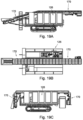
- a mobile underground tunnel borer arrangement 10 comprises a front or leading mobile tunnel boring unit 12 and at least one rear, trailing backup or auxiliary unit 14.
- the mobile tunnel boring unit 12 includes first drive means 16 to drive the mobile tunnel boring unit 12, a gripper arrangement 18 to facilitate boring (by providing the required gripping and thrusting), and a rotatable cutter head 20 fitted with cutters 22 to bore the tunnel face.
- the gripper arrangement 18 includes a front gripper assembly 24 and a rear gripper assembly 26.
- Each gripper assembly 24, 26 includes a support body 28, 30 and four movable gripper elements 32, 34 that can be extended and retracted, using first actuators (typically, hydraulic pistons), relative to the support body 28, 30.
- first actuators typically, hydraulic pistons
- the gripper elements 32, 34 grip against the tunnel wall and in the retracted position, the first drive means 16 can be operated to move the mobile tunnel boring unit 12.
- the gripper elements 32, 34 typically include gripper pads that are fitted on spherical joints.
- the spherical joints enable steering, both left and right steering and up and down steering.
- the front gripper assembly 24 moves forwards with the cutter head 20, and the rear gripper assembly 26 extends out to engage against the tunnel.
- the front gripper assembly 24 stabilises the cutter head 20 while the rear gripper assembly 26 provides thrust.
- the front gripper assembly 24 clamps against the tunnel and the rear gripper assembly 26 retracts.
- the top two gripper elements 32, 34 can retract, to enable the mobile tunnel boring unit 12 to be dragged through the tunnel.
- the four movable gripper elements 32, 34 extend at 45 degree angles around the support body 28, 30, so as to define an X.
- the front and rear gripper assemblies 24, 26 are fitted to either end of a torque shaft housing 42 for accommodating a torque shaft that connects a gearbox 44 with the cutter head 20.
- Second actuators 46 (typically hydraulic pistons) are arranged to extend and retract the support body 28, 30 of the front gripper assembly 24 and the cutter head 20 relative to the torque shaft housing 42.
- the cutter head 20 includes a central engaging face 48 with a plurality of (typically four) modular cutter segments 50 extending at an angle away from the central engaging face 48. This arrangement defines a tapered, self-centring arrangement.
- the cutter segments 50 can be removed from the cutter head 20 (similar to a raise borer head); in another version, the cutter segments 50 can be movably collapsible relative to the cutter head 20.
- the borer arrangement 10 includes a ventilation duct 64 that runs from the dust shield 52 all the way to a scrubber unit 66 at the back of the borer arrangement 10.
- the borer arrangement 10 further includes a fresh air pipe 68 to blow fresh air into the working area of the borer arrangement 10.
- the borer arrangement 10 includes a support drill 70 and related platform 72, which is disconnected from the mobile tunnel boring unit 12. In use, as the borer arrangement 10 is drilling and vibrating, the support drill 70 and platform 72 will be stable, thereby allowing personnel to work on top of the platform 72. In particular, a person can stand on top of the platform 72 can perform the necessary drilling for the support work. This drilling would typically be done from -30 degrees from horizontal all the way around to -30 degrees on the other side.
- the backup unit 14 includes second drive means 74 to drive the backup unit 14, and a support frame 76 on top of the second drive means 76.
- An advantage of having two separate units 12, 14 is to improve mobility and to allow all the required equipment, such as hydraulic power packs, gearboxes, motors, water and cable reels etc, to be arranged so as to provide a balanced arrangement.
- the borer arrangement 10 includes walkways 78 on both sides of the machine 10.
- the cutter head and cutters cutting forwardly, as described above they may be arranged to cut from the inside out. As a result, there is nothing pushing the borer arrangement back, thus simplifying the need for the gripper arrangements.
- This arrangement would also allow hydraulics and other equipment, and conveyors, to be brought through the centre of the head, and would allow hydraulic activation on the head in the front as well.
- the tracks 110 are mounted to a cross support 115 with pivot pins 117, to better accommodate the round shape of the bored tunnel.
- a hydraulic cylinder 119 is fitted between the cross support 115 and the support body 106 (not shown), to lift the upper part of the boring unit 102 relative to the tracks 110 (which will be explained in more detail further below). This is one configuration of a lifting configuration to lift the support body 106 relative to the tracks 110 (the other configuration is described further below).
- This lifting arrangement conveniently accommodates the round bored tunnel and is particularly useful to accommodate varying diameters of the boring unit 102, as will be explained in more detail further below with reference to Figure 17 , and to ensure alignment when assembling the mobile tunnel boring unit 102 to a cutter head 116 (explained in more detail further below).
- FIG 8 another lifting arrangement is shown, comprising two pairs of criss-cross lifting cylinders 400.
- the cylinders 400 may be actuated to lift the support body 106 (and thus the upper portion of the mobile tunnel boring unit 102) relative to the tracks 110.
- the crawler tracks 110 are powered by a diesel powered hydraulic motivator, which is latched to the back of the mobile tunnel boring unit 102.
- the crawler tracks 110 are operated by a handheld remote control, by one operator in close proximity to the boring unit 102.
- the mobile tunnel boring unit 102 further comprises a round rotatable cutter head 116 fitted with cutters 118 to bore the tunnel face 120 shown in Figure 6A .
- the round bored tunnel is particularly advantageous in underground situations, primarily due to its inherent strength.
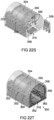
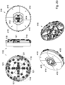
- the cutter head 116 includes a full face cutter head 116 with disc cutters 118, the cutter head 116 defining scoops 121 (best shown in Figure 23 ) and channels 122 (best shown in Figure 8 ) to allow cuttings and muck to pass automatically through the cutter head 116 for discharge into a muck hopper 402 (best shown in Figures 10 and 11B ) and collection onto a first conveyor arrangement 124 located immediately behind the cutter head 116 (as best shown in Figure 8 ).
- the cutter head 116 comprises four peripheral modular cutter segments 410 and a central cutter head segment 412.
- the size of the peripheral cutter segments 410 are variable, depending on the size of the tunnel to be bored, while the central cutter head segment 412 remains the same irrespective of the tunnel size, so as to define a common centre.
- the central cutter head segment 412 defines a central aperture 414 to enable the back loading of the cutters 118, as best shown in the cross-sectional perspective view indicated by arrow 416.
- the central cutter head segment 412 has tapered side walls 418, with the corresponding inner faces of the peripheral cutter segments 410 being tapered accordingly. This ensures a tight fit between the segments 410 and 412, with the central cutter head segment 412 in turn being connected to the main drive 134 (discussed further below) using a quick connection arrangement.
- the muck hopper 402 extends through the central aperture 414 of the central cutter head segment 412 to receive the cuttings for transport by the first conveyor arrangement 124.
- the first conveyor arrangement 124 extends through the mobile tunnel boring unit 102 for subsequent offloading onto a first backup unit 126, which is described in more detail further below.
- the first conveyor arrangement 124 comprises a front conveyor section 124.1 and a rear conveyor section 124.2, with the front conveyor section 124.1 being retractable away from the cutter head drive means 134, out from under the muck hopper 402, to allow access for cutter change and maintenance.
- the rear conveyor section 124.2 is typically enclosed under a cover 420, which is primarily used as a safety measure and to reduce dust within the mobile tunnel boring unit 102.
- the mobile tunnel boring unit 102 is fitted with a telescopic shield arrangement 128, as best shown in Figures 6A , 7 , 9 , 14A , 14B and 14C .
- the shield arrangement 128 comprises a front shield 130 proximate the front of the mobile tunnel boring unit 102, from which the cutter head 116 protrudes, and a rear shield 132 that surrounds at least an upper portion of the mobile tunnel boring unit 102.
- the front and rear shields 130, 132 operate telescopically relative to each other, to assist the mobility and agility of the boring unit 102 as the boring direction changes and curves.
- the front shield 130 in turn comprises a plurality of peripheral modular segments 130.1 to 130.4 joined together, which further assists with the compact and manoeuvrable design of the mobile tunnel boring unit 102.
- the shield arrangement 128 thus provides a fully supported zone proximate the tunnel face 120 being bored.
- the peripheral segments 130.1 to 130.4 define an aperture 131 in the middle, to accommodate the front conveyor section 124.1 therethrough.
- One of the segments 130.1 to 130.4 is a bottom/belly shield segment 130.4, which stabilises the mobile tunnel boring unit 102, in cooperation with gripper pads 156 (explained in more detail further below), by skidding on the tunnel invert at all times.
- the belly shield segment 130.4 is equipped with replaceable wear plates to extend its operating lifespan.
- the shield arrangement 128 is modular to ease transport, by limiting size and weight.
- the shield arrangement 128 is designed to be assembled quickly and efficiently, with reference to Figure 22R as well, with the shield interface providing quick alignment and easy access for fasteners.
- the front shield 130 (together with the cutter head 116, as described above) can be detached from the rest of the mobile tunnel boring unit 102, and is typically pre-installed in a starting chamber, as will be described in more detail further below with reference to Figures 21A to 21G , and in Figures 22A to 22W .
- the front shield 130 accommodates cutter head drive means 134, best shown in Figures 9 , 10 , 10B and 11 , to rotatingly drive the cutter head 116.
- the cutter head drive means 134 is mounted onto the cutter head 116, and typically comprises hydraulic drive motors that drive a ring gear which is stabilised by a thrust bearing.
- a sealing arrangement is used to prevent against the ingress of dust, thereby preventing against dust from penetrating the cutter head drive means 134.
- the drive means 134 defines an aperture 430 in the middle, as best shown in Figure 10 , to accommodate the front conveyor section 124.1 therethrough.
- the aperture 430 in conjunction with the central aperture 414 of the central cutter head segment 412, facilitates access to the cutters 118, for ongoing maintenance.
- the cutter head drive means 134 is shaped specifically to aid fast assembly of the front shield 130 in the correct sequence.
- a quick attachment method was developed to aid fast assembly/connection between the cutter head drive means 134 to the cutter head 116 when the cutter head 116 has been assembled in the cutting face.
- the cutter head 116 may also have varying sizes, as required in use.
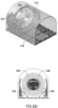
- FIGS. 6B and 182 in Figure 17 show two possible diameter sizes of the mobile tunnel boring unit 102 of the mobile underground tunnel borer arrangement 100, namely a 5.5 metre diameter machine (shown in Figure 6B and indicated by arrow 180 in Figure 17 ), and a 4.5 metre diameter machine (shown in Figure 6A and indicated by arrow 182 in Figure 17 ).
- an identical mobile tunnel boring unit 102 can be used for both sizes, with only the shield arrangement 128 (and in particular the front shield 130) and the cutter head 116 needing to be changed.
- the central cutter head segment 412 described above allows the four peripheral cutter segments 410 for the 4.5 m and 5.5 m configurations to be secured in place (described further below with reference to Figures 22K , 22L and 22M ).
- an additional bunker car 432 is typically used to provide additional storage capacity, as shown in Figure 6B .
- Figures 6A, 6B and 17 show the relative positioning of the support body 106 (and thus the upper part of the mobile tunnel boring unit 102), relative to the tracks 110, depending upon the machine size.
- the cylinder 119 (in one configuration) or the cylinders 400 (in the other configuration) are retracted, in order to lower mobile tunnel boring unit 102 (and in particular the support body 106).
- the support body 106 and mobile tunnel boring unit 102 are raised, with the cylinders 119, 400 accordingly being extended.
- an actuating arrangement 136 comprising a plurality of hydraulic thrust cylinders 138, extends between the cutter head drive means 134 and a pair of opposite gripper assemblies 154.
- the front shield 130 is secured to the outside of the main drive 134, whereas the rear shield 132 is secured to the rear end of the mobile tunnel boring unit 102, as shown in Figure 22V .
- the actuating arrangement 136 is arranged to telescopingly move the front shield 130 relative to the mobile tunnel boring unit 102 (and thus the rear shield 132). This telescoping movement further assists with the compact and manoeuvrable design of the mobile tunnel boring unit 102.
- the thrust cylinders 138 typically four pairs of thrust cylinders, two pairs on either side of the unit 102, extend slightly inwardly from the gripper assemblies 154 towards the cutter head drive means 134, as best shown in Figure 11B .
- This enables the mobile tunnel boring unit 102 to be steered in all directions (i.e. up, down, left and right, and thus even enabling spiral shafts to be bored), as best shown in Figure 15 .
- two paths 142, 144 are shown; in the first path 142, the cutter head 116 extends at an angle of 8.2 degrees relative to the rest of the borer arrangement 100, whereas in the second path 144, the cutter head 116 extends at an angle of 7.9 degrees relative to the rest of the borer arrangement 100.
- the mobile tunnel boring unit 102 has a turning radius of approximately 30 metres.
- the arrangement of the thrust cylinders 138 acts as a flexible link between the cutter head drive means 134 and the rest of the mobile tunnel boring unit 102, which allows for correction of the mobile tunnel boring unit 102 after rotational slippage.
- the thrust cylinders 138 are equipped with position sensors 139, enabling the mobile tunnel boring unit 102 to establish the position of the cutter head 116 relative to the rest of the mobile tunnel boring unit 102 (and in particular the gripper assemblies 154).
- the mobile tunnel boring unit 102 includes a gripper arrangement to facilitate boring (by providing the required gripping and thrusting).
- the gripper arrangement includes a pair of front, relatively smaller, gripper assemblies 152 (best shown in Figures 7 and 9 ), arranged to protrude from the front shield 130, and a pair of rear, relatively larger gripper assemblies 154, fitted to, so as to extend from, the support body 106.
- the smaller, gripper assemblies 152 define a V (and thus extend radially upwardly at 45 degrees), on either side of an upper edge of the front shield 130.
- the larger gripper assemblies 154 extend on opposite sides of the mobile tunnel boring unit 102, with cylinder barrels 155 (best shown in Figure 9 ) being carried on the support body 106, for guiding the movement of the gripper assemblies 154.
- the gripper assemblies 154 include movable, curved gripper elements 156. Under the control of the thrust cylinders 138, the gripper assemblies 154 can be extended and retracted, relative to the mobile tunnel boring unit 102. In the extended position, the gripper elements 156 grip against the tunnel wall, and in the retracted position, the mobile tunnel boring unit 102 is free to move forwards. In particular, in use, the mobile tunnel boring unit 102 remains in contact with the floor.
- the curved gripper elements 156 take the form of curved gripper pads that are fitted on pin type spherical joints to accommodate free movement and minimise pressure on the rock formation.
- the mobile tunnel boring unit 102 further includes a support drill rotation ring 160, and associated ring drive means 162 to rotate the ring 160 through 270 degrees, fitted proximate the rear end of the mobile tunnel boring unit 102.
- the support drill rotation ring 160 carries two spaced apart drills 164, to facilitate the fitting of rock bolt supports to the surrounding wall, and which can operate simultaneously to increase productivity i.e. the support bolts are drilled and installed simultaneously.
- the drills 164 are typically fitted to the rotation ring 160 to define a V-configuration. Roof bolts of up to 3 metres in length and/or support mesh can be fitted using this arrangement, as indicated by lines 165 in the fully drilling pattern.
- the ring 160 rotates through 270 degrees, stopping at four distinct positions or intervals, as shown, to enable the drills 164 to drill holes into the surrounding wall.
- the result is eight drilled holes 165, spaced apart at the wall, as indicated by x, by around 1.165 m.
- the ring 160 and drills 164 define an on-board rock support bolting system that can provide support while the mobile tunnel boring unit 102 is busy excavating. This results in a fully supported excavation, with the front shield 130 defining a primary support, and the roof bolts defining a secondary support.
- the mobile tunnel boring unit 102 includes one or more probe drills 440, as best shown in Figure 8 , safely housed within the rear shield 132. This allows drilling in advance, typically up to 30 metres, to locate bad ground conditions and/or water ahead of the boring unit 102. The probe drill position and orientation can be manually adjusted to allow cover drilling in three directions through the cutter head 116 and the front shield 130.
- the rear shield 132 includes a plurality of fingers 166 that define gaps through which the drills 164 can extend and drill. These fingers 166 guide and assist in the drilling operation of the support drills 164.
- the fingers 166 are hydraulically actuated to provide adjustment during transport and also to support the tunnel wall during support drilling, to protect the support drill operators 442 (as best shown in Figure 8 ).
- the first backup unit 126 is fitted with a second conveyor arrangement 170 to transport the cuttings and muck from the first conveyor arrangement 124 on the mobile tunnel boring unit 102 towards a second backup unit 172.
- the first backup unit 126 is fitted with the main hydraulic power pack, and an electric panel that is equipped with a PLC system.
- the first backup unit 126 is also fitted with a scrubber unit to assist with dust suppression.
- the second backup unit 172 is fitted with a third conveyor arrangement 174 to receive the cuttings and muck from the second conveyor arrangement 170 on the first backup unit 126 towards a truck 176.
- the second backup unit 172 is fitted with a cooling water circulation pumping system.
- the second backup unit 172 is also fitted with a main incoming transformer substation and also a dust extraction fan unit. Cable and hose reels are fitted as well to allow continuous operation for a distance of 300 meters.
- the first, second and third conveyor arrangements 124, 170, 174 are all collapsible, so as to improve and facilitate manoeuvrability, as shown in Figures 18A and 18B , 19A to 19C and 20A to 20C .
- the end portions of the conveyor arrangements 124, 170, 174 can be folded or pivoted downwardly, as best shown in Figures 18A , 19A and 20A .
- the conveyor arrangements 124, 170, 174 are designed with variable geometry, to enable them to be compacted to assist manoeuvrability during transportation.
- the conveyor arrangements 124, 170, 174 have a modular design to enable common parts inventory to ease spares and maintenance requirements.
- the borer arrangement may be monitored and controlled remotely, and is thus safe for working personnel.
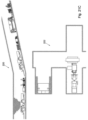
- a site is prepared by having a box-cut starting chamber 200 prepared, with a typical height of 6 meters and a length of around 12 metres.
- the site is further prepared by drilling supports for the chamber 200, as shown by arrow 202.
- Shuttering is then installed (arrow 204) with an LHD truck, with concrete then being pumped by a truck mixer (arrow 206).
- the machine sections are transported down the shaft in a cage, as shown by arrow 210. Material may then be transported down a decline shaft, provided there is at least a 2 metre passage height, as shown by arrow 212.
- the cutter head 116 is detachably secured to the mobile tunnel boring unit 102 with a quick attachment method (described further below with reference to Figures 22U , 22V and 22W ), which improves the efficiency of the boring cycle.
- the cutter head 116 comprises a plurality of segments that can be pre-assembled and pre-installed, typically together with the front shield (described above and further below with reference to Figures 22K , 22L and 22M ).
- muck is removed to a stockpile area by truck 232 (similar to truck 176 shown in Figure 6A ), with a replacement truck 234 (also similar to truck 176 shown in Figure 6A ) being ready to take its place so as to keep the process substantially continuous.
- the muck is then discharged at a stockpile area, as indicated by arrow 240 in Figure 21G .
- FIG. 22A to 22W the construction and use of a launching or starting frame 300 (shown in Figure 22T ), within a prepared starting chamber 302, will now be described.
- a first centre base frame component 304 is placed down on the ground, spaced apart from the tunnel face 306 to be drilled, as shown in Figure 22A .
- a number of additional centre base frame components 308 are fitted to the first centre base frame component 304, typically using connection plates 310, leading up to, so as to substantially abut against, the tunnel face 306.
- FIG 22B A number of side base frame components 312 are then fitted on either side of the assembled centre base frame components 304, 308, as shown in Figures 22C and 22D , again typically using connection plates 314.
- Figure 22D shows the resulting assembled base 316 for the starting frame 300.
- a first side frame component 318 is secured to the side base frame component 312, adjacent the tunnel face 306, using rods 320.
- a second side frame component 322 is secured to the opposite side base frame component 312, adjacent the tunnel face 306, using rods 324, as shown in Figure 22F .
- a cutter head backstop assembly 326 is provided to extend across the first and second side frame components 318, 322.
- a pair of cutter head backstop telescopic pipe supports 328, 330 are fitted to upper regions of the first and second side frame components 318, 322, as shown in the views of Figure 22G .
- a pair of mobile templates 332 are provided and fitted proximate the ends of the first and second side frame components 318, 322.
- a first pair of crawler track boards 334 are provided and fitted to the end of the assembled base 316.
- Figure 22K also shows a first cutter head segment 336 (corresponding to peripheral cutter head segment 410 shown in Figure 23 ) ready for installation.
- Additional cutter head segments 336 are installed, piece by piece, to ultimately define an outer cutter head ring 338, as shown in the views of Figure 22L .
- the cutter head ring is supported on the first pair of track boards 334.
- a central cutter head component 340 (corresponding to central cutter head segment 412 in Figure 23 ) is then fitted within the cutter head ring 338, as shown in Figure 22M (and the subsequent figures).
- a second pair of crawler track boards 342 are provided and fitted to the assembled base 316, adjacent the first pair of track boards 334.
- a front shield sector 344 is provided and supported on top of the second pair of track boards 342.
- the front shield sector 344 is typically secured in position using pins 346.
- a pair of main drive cylinder components 348 are placed in position, adjacent the first and second side frame components 318, 322. This figure also show a third side frame component 350, ready to be installed adjacent the first side frame component 318.
- a fourth side frame component 352 is also provided and installed, as shown in Figure 22R .
- This figure also shows a front shield 354 ready to be installed, with Figure 22S subsequently showing the front shield 354 fitted around the cutter head ring 338.
- Figure 22S also shows a third pair of crawler track boards 356 provided and fitted to the assembled base 316, adjacent the second pair of track boards 342.
- This figure also show a fifth side frame component 358, ready to be installed adjacent the third side frame component 350.
- a sixth side frame component 360 is also provided and installed, as shown in Figure 22T .
- This figure also shows a fourth pair of crawler track boards 362 provided and fitted to the assembled base 316, adjacent the third pair of track boards 356. The result is the now assembled starting frame 300.
- a manipulator 350 is provided for use by a telehandler 352, as shown in Figure 25 .
- the telehandler 352 is hydraulically powered and remote controlled.
- the manipulator 350 is arranged to pick up a component 354 corresponding to any of the cutter head and/or shield segments, drive the component 354 into the starting frame 300, and place it where required to facilitate the assembly or connection of the relevant component 354.
- the manipulator 350 is shown in more detail in Figure 26 , and typically comprises a rear plate 360 having an elongate support 362 that can be grabbed and lifted by a hooking arrangement 364 at the end of the telehandler 352.
- a support arrangement extends from the front of the rear plate 360, comprising a pair of spaced support plates 368, 370.
- a securing plate 372 is fitted across the ends of the support plates 368, 370, the securing plate 372 being pivotable relative to the support plates 368, 370, to enable the relevant component 354 to be placed where required.
- tunnel borer arrangements of the present invention is far more mobile and versatile than traditional TBMs of the type described above, and is relatively cheaper.
- the use of various interchangeable components greatly simplifies maintenance, thereby increasing overall efficiency of the machine.
- the present invention overcomes the need for drilling and blasting, with the inherent strength provided by the round shape of the bored tunnel being particularly advantageous underground.
Landscapes
- Engineering & Computer Science (AREA)
- Mining & Mineral Resources (AREA)
- Life Sciences & Earth Sciences (AREA)
- General Life Sciences & Earth Sciences (AREA)
- Geochemistry & Mineralogy (AREA)
- Geology (AREA)
- Environmental & Geological Engineering (AREA)
- Structural Engineering (AREA)
- Excavating Of Shafts Or Tunnels (AREA)
Claims (15)
- Mobile Tunnelbohreinheit (102), die Einheit (102) umfasst:einen Tragkörper (106), der durch erste Antriebsmittel (108) angetrieben wird, wobei die ersten Antriebsmittel (108) zum Antreiben der mobilen Tunnelbohreinheit (102) ein Paar von beabstandeten Raupenfahrwerken (110) in Kontakt mit dem Tunnelboden (112) und zugehörige Raupenantriebsmittel (114) zum Bewegen der Raupen (110) und somit des Tragkörpers (106) umfassen;ein Bohrkopfantriebsmittel (134), das sich an einem funktionell vorderen Ende des Tragkörpers (106) befindet und an dem ein drehbarer Bohrkopf (116) angebracht ist, der in einer Startkammer (200, 302) nahe einer Ortsbrust (120, 306), an der zu bohren ist, vorinstalliert wurde, um den drehbaren Bohrkopf (116) im Einsatz drehend anzutreiben;einen Aushubmaterialtrichter (402) und eine erste Förderanordnung (124), wobei der Bohrkopf (116) einen vollflächigen Bohrkopf (116) umfasst, der mit Schneidwerkzeugen zum Bohren an einer Ortsbrust (120, 306) ausgestattet ist, wobei der Bohrkopf (116) so angeordnet ist, dass Bohrklein durch den Bohrkopf (116) hindurchtreten kann, um in den Aushubmaterialtrichter (402) und auf die erste Förderanordnung (124) entladen zu werden, wobei die Bohrkopfantriebsmittel (134) und ein hinterer Abschnitt des Bohrkopfs (116) ausgerichtete zentrale Öffnungen (430, 414) definieren, durch die sich ein vorderer Teil der ersten Förderanordnung (124) erstrecken kann;eine teleskopische Schildanordnung (128) zum Abschirmen der Bohreinheit (102), wobei die Schildanordnung (128) einen vorderen Schild (130) nahe der Vorderseite der mobilen Tunnelbohreinheit (102) umfasst, aus dem der Bohrkopf (116) hervorsteht und der die Bohrkopfantriebsmittel (134) aufnimmt, wobei der vordere Schild (130) zusammen mit dem Bohrkopf (116) auch in der Startkammer (200, 302) vorinstalliert wurde, sowie einen hinteren Schild (132), der mindestens einen oberen Abschnitt der mobilen Tunnelbohreinheit (102) umgibt, wobei der vordere und hintere Schild (130, 132) teleskopartig relativ zueinander arbeiten, um Änderungen in der Bohrrichtung aufzunehmen; undeine Betätigungsanordnung (136), die eine Vielzahl hydraulischer Vortriebszylinder (138) umfasst, die sich zwischen dem Bohrkopfantriebsmittel (134) und einem Paar gegenüberliegender erster Greiferanordnungen (154) erstrecken.
- Mobile Tunnelbohreinheit (102) nach Anspruch 1, dadurch gekennzeichnet, dass die beabstandeten Raupenfahrwerke (110) der ersten Antriebsmittel (108) mit Drehzapfen (117) an einem Querträger (115) montiert sind, um der runden Form eines gebohrten Tunnels gerecht zu werden.
- Mobile Tunnelbohreinheit (102) nach Anspruch 2, wobei die mobile Tunnelbohreinheit (102) ferner einen Hydraulikzylinder (119) umfasst, der zwischen dem Querträger (115) und dem Tragkörper (106) angebracht ist, um den oberen Teil der Bohreinheit (102) relativ zu den Raupenfahrwerken (110) anzuheben.
- Mobile Tunnelbohreinheit (102) nach einem beliebigen der vorhergehenden Ansprüche, dadurch gekennzeichnet, dass der Bohrkopf (116) eine Vielzahl peripherer Bohrsegmente (410) und ein zentrales Bohrkopfsegment (412) umfasst, wobei das zentrale Bohrkopfsegment (412) verjüngte Seitenwände (418) aufweist und die entsprechenden Innenflächen der peripheren Bohrsegmente (410) dementsprechend verjüngt sind, um einen dichten Sitz sicherzustellen, wobei das zentrale Bohrkopfsegment (412) wiederum mit dem Bohrkopfantriebsmittel (134) verbindbar ist, wobei die Größe der peripheren Bohrsegmente (410) je nach Größe des zu bohrenden Tunnels variabel ist, während das zentrale Bohrkopfsegment (412) unabhängig von der zu bohrenden Tunnelgröße gleich bleibt.
- Mobile Tunnelbohreinheit (102) nach einem beliebigen der vorhergehenden Ansprüche, dadurch gekennzeichnet, dass sich die erste Förderanordnung (124) durch die mobile Tunnelbohreinheit (102) zum anschließenden Entladen auf eine erste Unterstützungseinheit (104) erstreckt, wobei die erste Förderanordnung (124) einen vorderen Förderabschnitt (124.1) und einen hinteren Förderabschnitt (124.2) umfasst, wobei der vordere Förderabschnitt (124.1) von dem Bohrkopfantriebsmittel (134) weg und unter dem Aushubmaterialtrichter (402) hervor zurückziehbar ist, um den Zugang zum Bohrkopf (116) zu ermöglichen.
- Mobile Tunnelbohreinheit (102) nach einem beliebigen der vorhergehenden Ansprüche, dadurch gekennzeichnet, dass der vordere Schild (130) eine Vielzahl von peripheren Segmenten (130.1, 130.2, 130.3, 130.4) umfasst, die miteinander verbunden sind, um einen vollständig unterstützten Schild nahe der Ortsbrust (120, 306) zu schaffen, wobei die peripheren Segmente (130.1, 130.2, 130.3, 130.4) eine zentrale Öffnung (131) definieren, um das Bohrkopfantriebsmittel (134) aufzunehmen, und durch die sich ein vorderer Teil der ersten Förderanordnung (124) und der Aushubmaterialtrichter (402) erstrecken können, wobei eines der Segmente (130.4) ein Bauchschildsegment (130.4) umfasst, um die mobile Tunnelbohreinheit (102) durch Gleiten entlang der Tunnelsohle zu stabilisieren, ferner dadurch gekennzeichnet, dass der vordere Schild (130) an der Außenseite des Bohrkopfantriebsmittels (134) befestigt ist und der hintere Schild (132) an einem hinteren Ende der mobilen Tunnelbohreinheit (102) befestigt ist, um es der Betätigungsanordnung (136) zu ermöglichen, den vorderen Schild (130) relativ zu der mobilen Tunnelbohreinheit (102) und dem hinteren Schild (132) teleskopartig zu bewegen.
- Mobile Tunnelbohreinheit (102) nach einem beliebigen der vorhergehenden Ansprüche, dadurch gekennzeichnet, dass die Vortriebszylinder (138) vier Paare von Vortriebszylindern (138) umfassen, zwei Paare auf jeder Seite der Einheit (102), die sich von den ersten Greiferanordnungen (154) nach innen in Richtung des Bohrkopfantriebsmittels (134) erstrecken, um die Lenkung der mobilen Tunnelbohreinheit (102) in alle Richtungen zu ermöglichen, wobei die Enden der Vortriebszylinder mit sphärischen Kugelgelenken (140) ausgestattet sind, um eine flexible Verbindung zwischen dem Bohrkopfantriebsmittel (134) und dem Rest der mobilen Tunnelbohreinheit (102) zu schaffen.
- Mobile Tunnelbohreinheit (102) nach einem beliebigen der vorhergehenden Ansprüche, dadurch gekennzeichnet, dass die mobile Tunnelbohreinheit (102) eine Greiferanordnung umfasst, um das Bohren durch Bewirken des erforderlichen Greifens und Schiebens zu ermöglichen, wobei die Greiferanordnung ein Paar vorderer, relativ kleinerer zweiter Greiferanordnungen (152) umfasst, die so angeordnet sind, dass sie aus dem vorderen Schild hervorstehen, wobei die ersten Greiferanordnungen (154) ein Paar hinterer, relativ größerer erster Greiferanordnungen (154) umfassen, die so angebracht sind, dass sie von dem Tragkörper (106) vorstehen, ferner dadurch gekennzeichnet, dass die zweiten Greiferanordnungen (152) ein V definieren, sodass sie sich radial nach oben zu beiden Seiten einer oberen Kante des vorderen Schilds (130) erstrecken, und die ersten Greiferanordnungen (154) sich auf gegenüberliegenden Seiten der mobilen Tunnelbohreinheit (102) erstrecken, wobei Zylinderrohre (155) auf dem Tragkörper (106) getragen werden, um die Bewegung der ersten Greiferanordnungen (154) zu führen, wobei die ersten Greiferanordnungen (154) bewegliche, gebogene Greiferelemente umfassen (156).
- Mobile Tunnelbohreinheit (102) nach Anspruch 8, dadurch gekennzeichnet, dass die ersten Greiferanordnungen (154) unter der Steuerung durch die Vortriebszylinder (138) relativ zu der mobilen Tunnelbohreinheit (102) ausgefahren und eingefahren werden können, wobei die Greiferelemente (156) in der ausgefahrenen Stellung die Tunnelwand greifen, und in der eingefahrenen Stellung die mobile Tunnelbohreinheit (102) frei nach vorne bewegt werden kann, während die zweiten Greiferanordnungen (152) ausgefahren sind, um die Tunnelwand zu greifen, wobei die Betätigungsanordnung (136) dann verwendet wird, um den hinteren Teil der mobilen Tunnelbohreinheit (102) nach vorne zu ziehen.
- Mobile Tunnelbohreinheit (102) nach einem beliebigen der vorhergehenden Ansprüche, dadurch gekennzeichnet, dass die mobile Tunnelbohreinheit (102) ferner einen Ankerbohrer-Drehring (160) umfasst, der nahe dem hinteren Ende der mobilen Tunnelbohreinheit (102) angebracht ist, sowie zugehörige Ringantriebsmittel (162) zum Drehen des Rings, wobei der Ankerbohrer-Drehring (160) mindestens zwei beabstandete Ankerbohrer (164) trägt, um das Anbringen von Felsankern an der umgebenden Wand zu ermöglichen, und die gleichzeitig arbeiten können, wobei der Ring (160) und die Ankerbohrer (164) ein bordeigenes Felssicherungsankersystem bilden, das für eine Sicherung sorgt, während die mobile Tunnelbohreinheit (102) mit dem Ausheben beschäftigt ist.
- Mobile Tunnelbohreinheit (102) nach Anspruch 10, dadurch gekennzeichnet, dass der hintere Schild (132) eine Vielzahl von Fingern (166) umfasst, die Lücken definieren, durch die die Ankerbohrer (164) sich erstrecken und bohren können, wobei die Finger (166) den Bohrvorgang des Ankerbohrers (164) führen und unterstützen, wobei die mobile Tunnelbohreinheit (102) ferner mindestens einen Sondierbohrer (440) umfasst, der sicher innerhalb des hinteren Schilds (132) untergebracht ist, um das Bohren im Voraus zu ermöglichen, um schlechte Bodenbedingungen und/oder Wasser vor der Bohreinheit (102) festzustellen.
- Mobile unterirdische Tunnelbohranordnung (100), dadurch gekennzeichnet, dass die Anordnung (100) umfasst:eine mobile Tunnelbohreinheit (102) nach einem beliebigen der Ansprüche 1 bis 11; undmindestens eine hintere, nachlaufende Unterstützungseinheit (126, 172), die im Betrieb hinter der mobilen Tunnelbohreinheit (102) angeordnet ist.
- Mobile unterirdische Tunnelbohranordnung (100) nach Anspruch 12, dadurch gekennzeichnet, dass eine erste Unterstützungseinheit (126) mit einer zweiten Förderanordnung (170) ausgestattet ist, um das Bohrklein und den Aushub von der ersten Förderanordnung (124) auf der mobilen Tunnelbohreinheit (102) zu einer zweiten Unterstützungseinheit (172) zu transportieren, wobei die zweite Unterstützungseinheit (172) mit einer dritten Förderanordnung (174) ausgestattet ist, um das Bohrklein und den Aushub von der zweiten Förderanordnung (170) auf der ersten Unterstützungseinheit (126) zu einem Lastwagen (176) oder Bunkerwagen (432) zu transportieren, wobei die erste, zweite und dritte Förderanordnung (124, 170, 174) alle einklappbar sind, um die Manövrierfähigkeit zu verbessern, wobei die Endabschnitte der Förderanordnungen (124, 170, 174) nach unten gefaltet oder geschwenkt werden können.
- Verfahren zum Bohren eines Tunnels, dadurch gekennzeichnet, dass das Verfahren umfasst:Konstruieren eines Startrahmens (300) innerhalb einer Startkammer (200, 302), umfassend das Zusammenbauen einer Vielzahl von Basisrahmenkomponenten (304, 308, 312) auf dem Boden innerhalb der Kammer (200, 302), um einen Basisrahmen zu definieren, der nach oben zu einer Ortsbrust (120, 306), an der zu bohren ist, führt;Anbringen eines Paars von Seitenrahmenkomponenten (318, 322) auf beiden Seiten des Basisrahmens, angrenzend an die Ortsbrust (120, 306);Zusammenbauen einer Vielzahl peripherer Bohrkopfsegmente (336) an dem Ende der Kammer (200, 302) im Wesentlichen angrenzend an die Ortsbrust (120, 306), an der zu bohren ist, um letztendlich einen äußeren Bohrkopfring (338) zu definieren;Anbringen eines zentralen Bohrkopfsegments (340) in der Mitte des Bohrkopfrings (338), um einen Bohrkopf (116) zu definieren;Anbringen eines Bauchvorderschildsegments (130.4) auf dem Boden angrenzend zum Bohrkopf (116);Zusammenbauen einer Vielzahl von Vorderschildsegmenten (354) über dem Bohrkopf (116) und Befestigen dieser Segmente (354) an dem Bauchvorderschildsegment (130.4), um einen Vorderschild (130) zu definieren;Anbringen eines Hinterschilds (132) auf einer mobilen Tunnelbohreinheit (102) nach einem beliebigen der Ansprüche 1 bis 11; undVerbinden der mobilen Tunnelbohreinheit (102) mit dem Bohrkopf (116) und dem Vorderschild (130).
- Verfahren nach Anspruch 14, dadurch gekennzeichnet, dass zusätzliche Seitenrahmenkomponenten (350, 358) angebracht werden, während der Zusammenbau voranschreitet, ferner dadurch gekennzeichnet, dass ein Manipulator (350) zur Verwendung durch einen Teleskoplader (352) zur Unterstützung des Zusammenbaus der Bohrkopfsegmente (336) und der Schildsegmente (354) innerhalb des Startrahmens (300) vorgesehen ist, wobei der Manipulator (350) eine Rückplatte (360) umfasst, die eine längliche Stütze (362) aufweist, die von einer Hakenanordnung (364) gegriffen und angehoben werden kann.
Applications Claiming Priority (4)
| Application Number | Priority Date | Filing Date | Title |
|---|---|---|---|
| ZA201702323 | 2017-07-31 | ||
| ZA201707079 | 2017-10-19 | ||
| ZA201800727 | 2018-02-05 | ||
| PCT/IB2018/055713 WO2019025959A1 (en) | 2017-07-31 | 2018-07-31 | MOBILE UNDERGROUND TUNNELING ARRANGEMENT |
Publications (4)
| Publication Number | Publication Date |
|---|---|
| EP3662142A1 EP3662142A1 (de) | 2020-06-10 |
| EP3662142A4 EP3662142A4 (de) | 2021-05-05 |
| EP3662142C0 EP3662142C0 (de) | 2025-02-26 |
| EP3662142B1 true EP3662142B1 (de) | 2025-02-26 |
Family
ID=65233482
Family Applications (1)
| Application Number | Title | Priority Date | Filing Date |
|---|---|---|---|
| EP18841555.8A Active EP3662142B1 (de) | 2017-07-31 | 2018-07-31 | Fahrbare unterirdische tunnelbohrvorrichtung |
Country Status (8)
| Country | Link |
|---|---|
| US (1) | US11434762B2 (de) |
| EP (1) | EP3662142B1 (de) |
| CN (1) | CN111684144B (de) |
| AU (1) | AU2018311427B2 (de) |
| CA (1) | CA3071590A1 (de) |
| ES (1) | ES3027944T3 (de) |
| PL (1) | PL3662142T3 (de) |
| WO (1) | WO2019025959A1 (de) |
Families Citing this family (18)
| Publication number | Priority date | Publication date | Assignee | Title |
|---|---|---|---|---|
| AU2019449030B2 (en) * | 2019-06-05 | 2022-02-03 | China University Of Mining And Technology, Beijing | Mining machine applicable to fluidized mining of ore bodies and mining method |
| CN110836118B (zh) * | 2019-12-11 | 2024-11-01 | 广西中科聚能环保投资有限公司 | 一种在高地应力高地质危害下快速安全的隧洞施工的设备及方法 |
| CN111042827A (zh) * | 2019-12-26 | 2020-04-21 | 中联重科股份有限公司 | 多臂掘进机 |
| US11905835B1 (en) * | 2020-09-17 | 2024-02-20 | TopEng Inc. | Tunnel digging machine (TDM) |
| WO2022063326A1 (zh) * | 2020-09-28 | 2022-03-31 | 中煤科工开采研究院有限公司 | 一种喷涂临时支护与锚杆永久支护方法及系统 |
| AT17605U1 (de) * | 2021-03-23 | 2022-08-15 | Porr Bau Gmbh | Tunnelbohranordnung und Verfahren zum Erstellen eines Tunnels |
| CN113073936A (zh) * | 2021-03-26 | 2021-07-06 | 中国地质调查局西安地质调查中心(西北地质科技创新中心) | 一种钻动推送结构及铁矿边界探测装置 |
| CN113417656A (zh) * | 2021-08-09 | 2021-09-21 | 太原理工大学 | 一种小直径tbm出渣结构及隧道掘进机 |
| CN114017053B (zh) * | 2021-11-05 | 2023-07-11 | 中冶集团武汉勘察研究院有限公司 | 一种地下空间回廊式施工装置及使用该装置进行施工的方法 |
| CN114033414B (zh) * | 2021-11-08 | 2023-08-25 | 中国煤炭科工集团太原研究院有限公司 | 巷道掘进系统 |
| CN114233321A (zh) * | 2021-11-11 | 2022-03-25 | 中铁隧道集团二处有限公司 | 一种带除尘功能的盾构机渣土排出装置 |
| CN114542076B (zh) * | 2022-03-01 | 2025-02-18 | 中交一公局集团有限公司 | 一种撑靴式竖向掘进机深大竖井掘进方法 |
| JP7781496B2 (ja) * | 2022-03-18 | 2025-12-08 | 株式会社奥村組 | シールド掘進機の排土設備を構成する排土ポンプの設置方法 |
| CN114810096B (zh) * | 2022-05-24 | 2025-12-09 | 中铁第五勘察设计院集团有限公司 | 隧道维养列车及施工方法 |
| CN115506820A (zh) * | 2022-11-02 | 2022-12-23 | 上海市基础工程集团有限公司 | 用于超大直径盾构隧道内部弧形构件拼装的精调装置 |
| CN116122835B (zh) * | 2023-04-14 | 2023-06-20 | 太原理工大学 | 适用于紧凑型全断面掘进机的扭矩系统及掘进机 |
| CN117685002B (zh) * | 2023-12-28 | 2025-09-30 | 中国铁建重工集团股份有限公司 | 超前钻机设备和盾构机 |
| US12410660B1 (en) * | 2025-01-13 | 2025-09-09 | University Of Science And Technology Beijing | Full-face shaft boring machine, boring system, and boring method |
Family Cites Families (14)
| Publication number | Priority date | Publication date | Assignee | Title |
|---|---|---|---|---|
| US2766978A (en) * | 1955-04-25 | 1956-10-16 | Goodman Mfg Co | Rotary head tunneling machine having oppositely rotating head portions |
| US4390211A (en) * | 1979-06-29 | 1983-06-28 | Thompson Thomas M | Continuous miner with cutter assembly attitude adjustment |
| GB2065747A (en) * | 1979-11-27 | 1981-07-01 | Markham & Co Ltd | Improvements in or relating to tunnelling |
| US4548443A (en) * | 1984-07-03 | 1985-10-22 | The Robbins Company | Tunnel boring machine |
| DE4015462A1 (de) * | 1990-05-14 | 1991-11-21 | Wirth Co Kg Masch Bohr | Verfahren und maschine zum vortreiben von strecken, tunneln o. dgl. |
| US5527099A (en) * | 1994-05-09 | 1996-06-18 | Fikse; Tyman H. | Tunnel boring machine anchor shoe structure and process of operating a tunnel boring machine having such anchor shoe structure |
| JPH08253953A (ja) * | 1996-01-31 | 1996-10-01 | Hashimoto Setsubi Kogyosho:Kk | 空気による土砂の輸送方法 |
| EP0812979A1 (de) * | 1996-06-14 | 1997-12-17 | Construction & Tunneling Services, Inc. | Tunnelvortriebsmaschine und Verfahren |
| DE19722000A1 (de) * | 1997-05-27 | 1998-12-03 | Wirth Co Kg Masch Bohr | Tunnelbohrmaschine |
| AT407422B (de) * | 1997-11-04 | 2001-03-26 | Tamrock Voest Alpine Bergtech | Schrämmaschine |
| US7832960B2 (en) * | 2008-12-17 | 2010-11-16 | The Robbins Company | All-conditions tunnel boring machine |
| AU2011285755A1 (en) * | 2010-08-03 | 2013-02-28 | Joy Mm Delaware, Inc. | Underground boring machine |
| CN205277432U (zh) * | 2015-12-30 | 2016-06-01 | 中国神华能源股份有限公司 | 一种快速掘进巷道的系统 |
| CN105569701B (zh) * | 2016-03-03 | 2017-08-29 | 辽宁工程技术大学 | 适用于硬岩巷道掘进的迈步式掘进支护装置 |
-
2018
- 2018-07-31 AU AU2018311427A patent/AU2018311427B2/en active Active
- 2018-07-31 ES ES18841555T patent/ES3027944T3/es active Active
- 2018-07-31 WO PCT/IB2018/055713 patent/WO2019025959A1/en not_active Ceased
- 2018-07-31 CA CA3071590A patent/CA3071590A1/en active Pending
- 2018-07-31 PL PL18841555.8T patent/PL3662142T3/pl unknown
- 2018-07-31 CN CN201880059502.8A patent/CN111684144B/zh active Active
- 2018-07-31 US US16/635,852 patent/US11434762B2/en active Active
- 2018-07-31 EP EP18841555.8A patent/EP3662142B1/de active Active
Also Published As
| Publication number | Publication date |
|---|---|
| WO2019025959A1 (en) | 2019-02-07 |
| EP3662142C0 (de) | 2025-02-26 |
| EP3662142A4 (de) | 2021-05-05 |
| AU2018311427B2 (en) | 2024-08-01 |
| ES3027944T3 (en) | 2025-06-17 |
| CA3071590A1 (en) | 2019-02-07 |
| CN111684144B (zh) | 2023-02-17 |
| CN111684144A (zh) | 2020-09-18 |
| US11434762B2 (en) | 2022-09-06 |
| AU2018311427A1 (en) | 2020-03-19 |
| EP3662142A1 (de) | 2020-06-10 |
| PL3662142T3 (pl) | 2025-11-12 |
| US20200370434A1 (en) | 2020-11-26 |
Similar Documents
| Publication | Publication Date | Title |
|---|---|---|
| EP3662142B1 (de) | Fahrbare unterirdische tunnelbohrvorrichtung | |
| US10844664B2 (en) | Gantry and quick connect mechanism for interchanging drilling and bolting assemblies and method of interchanging bolting assemblies | |
| CN101705820B (zh) | 钻煤机 | |
| CN114278305B (zh) | 扩孔式竖井掘进机及其施工方法 | |
| CN117307036A (zh) | 一种井下大直径钻孔设备及施工方法 | |
| JPS61502828A (ja) | 竪坑堀削装置および方法 | |
| AU6478300A (en) | Three dimensional multi-phase tunneling method and equipments thereof | |
| EP0115426B1 (de) | Schachtbohrmaschine | |
| CN112343617B (zh) | 一种自动化矿用巷道掘进系统 | |
| CN201568055U (zh) | 钻煤机 | |
| CN113565521B (zh) | 一种联络通道掘进装备及一种联络通道施工方法 | |
| RU2141030C1 (ru) | Устройство для сооружения шахтных стволов | |
| AU2004216593B2 (en) | Combination panline and utility drilling or bolting unit | |
| CN113482654B (zh) | 一种联络通道掘进机及一种联络通道施工方法 | |
| US3877717A (en) | Multi-purpose vehicle for use underground | |
| US3851481A (en) | Multi-purpose vehicle for use underground | |
| US11274551B2 (en) | Material handling apparatus for a mining machine | |
| CA2336200A1 (en) | Tunnel boring machinery | |
| US20240076983A1 (en) | Tunnel Extraction Machine (TEM) | |
| USRE28707E (en) | Multi-purpose vehicle for use underground | |
| SU1213210A1 (ru) | Тоннельный рычажный крепеукладчик | |
| EA035546B1 (ru) | Роторный проходческий комбайн и способ извлечения скальной породы под землей | |
| WO2024130312A1 (en) | Underground mining system and method | |
| CN120830522A (zh) | 一种斜井钻护一体化台车 | |
| CN121024654A (zh) | 一种隧道衬砌钢筋辅助上料结构及施工方法 |
Legal Events
| Date | Code | Title | Description |
|---|---|---|---|
| STAA | Information on the status of an ep patent application or granted ep patent |
Free format text: STATUS: THE INTERNATIONAL PUBLICATION HAS BEEN MADE |
|
| PUAI | Public reference made under article 153(3) epc to a published international application that has entered the european phase |
Free format text: ORIGINAL CODE: 0009012 |
|
| STAA | Information on the status of an ep patent application or granted ep patent |
Free format text: STATUS: REQUEST FOR EXAMINATION WAS MADE |
|
| 17P | Request for examination filed |
Effective date: 20200302 |
|
| AK | Designated contracting states |
Kind code of ref document: A1 Designated state(s): AL AT BE BG CH CY CZ DE DK EE ES FI FR GB GR HR HU IE IS IT LI LT LU LV MC MK MT NL NO PL PT RO RS SE SI SK SM TR |
|
| AX | Request for extension of the european patent |
Extension state: BA ME |
|
| DAV | Request for validation of the european patent (deleted) | ||
| DAX | Request for extension of the european patent (deleted) | ||
| A4 | Supplementary search report drawn up and despatched |
Effective date: 20210408 |
|
| RIC1 | Information provided on ipc code assigned before grant |
Ipc: E21D 9/11 20060101AFI20210331BHEP Ipc: E21D 9/087 20060101ALI20210331BHEP Ipc: E21D 9/12 20060101ALI20210331BHEP Ipc: E21D 9/06 20060101ALI20210331BHEP Ipc: E21D 9/10 20060101ALI20210331BHEP |
|
| STAA | Information on the status of an ep patent application or granted ep patent |
Free format text: STATUS: EXAMINATION IS IN PROGRESS |
|
| 17Q | First examination report despatched |
Effective date: 20230102 |
|
| GRAP | Despatch of communication of intention to grant a patent |
Free format text: ORIGINAL CODE: EPIDOSNIGR1 |
|
| STAA | Information on the status of an ep patent application or granted ep patent |
Free format text: STATUS: GRANT OF PATENT IS INTENDED |
|
| INTG | Intention to grant announced |
Effective date: 20231010 |
|
| GRAS | Grant fee paid |
Free format text: ORIGINAL CODE: EPIDOSNIGR3 |
|
| GRAA | (expected) grant |
Free format text: ORIGINAL CODE: 0009210 |
|
| STAA | Information on the status of an ep patent application or granted ep patent |
Free format text: STATUS: THE PATENT HAS BEEN GRANTED |
|
| AK | Designated contracting states |
Kind code of ref document: B1 Designated state(s): AL AT BE BG CH CY CZ DE DK EE ES FI FR GB GR HR HU IE IS IT LI LT LU LV MC MK MT NL NO PL PT RO RS SE SI SK SM TR |
|
| REG | Reference to a national code |
Ref country code: GB Ref legal event code: FG4D |
|
| REG | Reference to a national code |
Ref country code: CH Ref legal event code: EP |
|
| REG | Reference to a national code |
Ref country code: DE Ref legal event code: R096 Ref document number: 602018079665 Country of ref document: DE |
|
| REG | Reference to a national code |
Ref country code: IE Ref legal event code: FG4D |
|
| U01 | Request for unitary effect filed |
Effective date: 20250326 |
|
| U07 | Unitary effect registered |
Designated state(s): AT BE BG DE DK EE FI FR IT LT LU LV MT NL PT RO SE SI Effective date: 20250401 |
|
| REG | Reference to a national code |
Ref country code: ES Ref legal event code: FG2A Ref document number: 3027944 Country of ref document: ES Kind code of ref document: T3 Effective date: 20250617 |
|
| PG25 | Lapsed in a contracting state [announced via postgrant information from national office to epo] |
Ref country code: RS Free format text: LAPSE BECAUSE OF FAILURE TO SUBMIT A TRANSLATION OF THE DESCRIPTION OR TO PAY THE FEE WITHIN THE PRESCRIBED TIME-LIMIT Effective date: 20250526 |
|
| PG25 | Lapsed in a contracting state [announced via postgrant information from national office to epo] |
Ref country code: NO Free format text: LAPSE BECAUSE OF FAILURE TO SUBMIT A TRANSLATION OF THE DESCRIPTION OR TO PAY THE FEE WITHIN THE PRESCRIBED TIME-LIMIT Effective date: 20250526 Ref country code: IS Free format text: LAPSE BECAUSE OF FAILURE TO SUBMIT A TRANSLATION OF THE DESCRIPTION OR TO PAY THE FEE WITHIN THE PRESCRIBED TIME-LIMIT Effective date: 20250626 |
|
| PG25 | Lapsed in a contracting state [announced via postgrant information from national office to epo] |
Ref country code: HR Free format text: LAPSE BECAUSE OF FAILURE TO SUBMIT A TRANSLATION OF THE DESCRIPTION OR TO PAY THE FEE WITHIN THE PRESCRIBED TIME-LIMIT Effective date: 20250226 |
|
| U20 | Renewal fee for the european patent with unitary effect paid |
Year of fee payment: 8 Effective date: 20250606 |
|
| PG25 | Lapsed in a contracting state [announced via postgrant information from national office to epo] |
Ref country code: GR Free format text: LAPSE BECAUSE OF FAILURE TO SUBMIT A TRANSLATION OF THE DESCRIPTION OR TO PAY THE FEE WITHIN THE PRESCRIBED TIME-LIMIT Effective date: 20250527 |
|
| PG25 | Lapsed in a contracting state [announced via postgrant information from national office to epo] |
Ref country code: SM Free format text: LAPSE BECAUSE OF FAILURE TO SUBMIT A TRANSLATION OF THE DESCRIPTION OR TO PAY THE FEE WITHIN THE PRESCRIBED TIME-LIMIT Effective date: 20250226 |
|
| PGFP | Annual fee paid to national office [announced via postgrant information from national office to epo] |
Ref country code: ES Payment date: 20250827 Year of fee payment: 8 |
|
| PGFP | Annual fee paid to national office [announced via postgrant information from national office to epo] |
Ref country code: TR Payment date: 20250729 Year of fee payment: 8 |
|
| PG25 | Lapsed in a contracting state [announced via postgrant information from national office to epo] |
Ref country code: CZ Free format text: LAPSE BECAUSE OF FAILURE TO SUBMIT A TRANSLATION OF THE DESCRIPTION OR TO PAY THE FEE WITHIN THE PRESCRIBED TIME-LIMIT Effective date: 20250226 |
|
| PG25 | Lapsed in a contracting state [announced via postgrant information from national office to epo] |
Ref country code: SK Free format text: LAPSE BECAUSE OF FAILURE TO SUBMIT A TRANSLATION OF THE DESCRIPTION OR TO PAY THE FEE WITHIN THE PRESCRIBED TIME-LIMIT Effective date: 20250226 |
|
| PLBE | No opposition filed within time limit |
Free format text: ORIGINAL CODE: 0009261 |
|
| STAA | Information on the status of an ep patent application or granted ep patent |
Free format text: STATUS: NO OPPOSITION FILED WITHIN TIME LIMIT |
|
| PGFP | Annual fee paid to national office [announced via postgrant information from national office to epo] |
Ref country code: PL Payment date: 20250723 Year of fee payment: 8 |
|
| 26N | No opposition filed |
Effective date: 20251127 |