EP3661421B1 - Convergent x-ray imaging device and method - Google Patents
Convergent x-ray imaging device and method Download PDFInfo
- Publication number
- EP3661421B1 EP3661421B1 EP18841917.0A EP18841917A EP3661421B1 EP 3661421 B1 EP3661421 B1 EP 3661421B1 EP 18841917 A EP18841917 A EP 18841917A EP 3661421 B1 EP3661421 B1 EP 3661421B1
- Authority
- EP
- European Patent Office
- Prior art keywords
- ray
- output beam
- laser
- gamma
- compton
- Prior art date
- Legal status (The legal status is an assumption and is not a legal conclusion. Google has not performed a legal analysis and makes no representation as to the accuracy of the status listed.)
- Active
Links
Images


Classifications
-
- A—HUMAN NECESSITIES
- A61—MEDICAL OR VETERINARY SCIENCE; HYGIENE
- A61B—DIAGNOSIS; SURGERY; IDENTIFICATION
- A61B6/00—Apparatus or devices for radiation diagnosis; Apparatus or devices for radiation diagnosis combined with radiation therapy equipment
- A61B6/40—Arrangements for generating radiation specially adapted for radiation diagnosis
- A61B6/4064—Arrangements for generating radiation specially adapted for radiation diagnosis specially adapted for producing a particular type of beam
- A61B6/4085—Cone-beams
-
- A—HUMAN NECESSITIES
- A61—MEDICAL OR VETERINARY SCIENCE; HYGIENE
- A61B—DIAGNOSIS; SURGERY; IDENTIFICATION
- A61B6/00—Apparatus or devices for radiation diagnosis; Apparatus or devices for radiation diagnosis combined with radiation therapy equipment
- A61B6/06—Diaphragms
-
- A—HUMAN NECESSITIES
- A61—MEDICAL OR VETERINARY SCIENCE; HYGIENE
- A61B—DIAGNOSIS; SURGERY; IDENTIFICATION
- A61B6/00—Apparatus or devices for radiation diagnosis; Apparatus or devices for radiation diagnosis combined with radiation therapy equipment
- A61B6/40—Arrangements for generating radiation specially adapted for radiation diagnosis
- A61B6/4035—Arrangements for generating radiation specially adapted for radiation diagnosis the source being combined with a filter or grating
-
- A—HUMAN NECESSITIES
- A61—MEDICAL OR VETERINARY SCIENCE; HYGIENE
- A61B—DIAGNOSIS; SURGERY; IDENTIFICATION
- A61B6/00—Apparatus or devices for radiation diagnosis; Apparatus or devices for radiation diagnosis combined with radiation therapy equipment
- A61B6/42—Arrangements for detecting radiation specially adapted for radiation diagnosis
- A61B6/4208—Arrangements for detecting radiation specially adapted for radiation diagnosis characterised by using a particular type of detector
- A61B6/4258—Arrangements for detecting radiation specially adapted for radiation diagnosis characterised by using a particular type of detector for detecting non x-ray radiation, e.g. gamma radiation
-
- A—HUMAN NECESSITIES
- A61—MEDICAL OR VETERINARY SCIENCE; HYGIENE
- A61B—DIAGNOSIS; SURGERY; IDENTIFICATION
- A61B6/00—Apparatus or devices for radiation diagnosis; Apparatus or devices for radiation diagnosis combined with radiation therapy equipment
- A61B6/48—Diagnostic techniques
- A61B6/483—Diagnostic techniques involving scattered radiation
-
- A—HUMAN NECESSITIES
- A61—MEDICAL OR VETERINARY SCIENCE; HYGIENE
- A61B—DIAGNOSIS; SURGERY; IDENTIFICATION
- A61B6/00—Apparatus or devices for radiation diagnosis; Apparatus or devices for radiation diagnosis combined with radiation therapy equipment
- A61B6/48—Diagnostic techniques
- A61B6/484—Diagnostic techniques involving phase contrast X-ray imaging
-
- A—HUMAN NECESSITIES
- A61—MEDICAL OR VETERINARY SCIENCE; HYGIENE
- A61B—DIAGNOSIS; SURGERY; IDENTIFICATION
- A61B6/00—Apparatus or devices for radiation diagnosis; Apparatus or devices for radiation diagnosis combined with radiation therapy equipment
- A61B6/48—Diagnostic techniques
- A61B6/485—Diagnostic techniques involving fluorescence X-ray imaging
-
- A—HUMAN NECESSITIES
- A61—MEDICAL OR VETERINARY SCIENCE; HYGIENE
- A61B—DIAGNOSIS; SURGERY; IDENTIFICATION
- A61B6/00—Apparatus or devices for radiation diagnosis; Apparatus or devices for radiation diagnosis combined with radiation therapy equipment
- A61B6/52—Devices using data or image processing specially adapted for radiation diagnosis
- A61B6/5205—Devices using data or image processing specially adapted for radiation diagnosis involving processing of raw data to produce diagnostic data
-
- G—PHYSICS
- G01—MEASURING; TESTING
- G01N—INVESTIGATING OR ANALYSING MATERIALS BY DETERMINING THEIR CHEMICAL OR PHYSICAL PROPERTIES
- G01N23/00—Investigating or analysing materials by the use of wave or particle radiation, e.g. X-rays or neutrons, not covered by groups G01N3/00 – G01N17/00, G01N21/00 or G01N22/00
- G01N23/02—Investigating or analysing materials by the use of wave or particle radiation, e.g. X-rays or neutrons, not covered by groups G01N3/00 – G01N17/00, G01N21/00 or G01N22/00 by transmitting the radiation through the material
- G01N23/04—Investigating or analysing materials by the use of wave or particle radiation, e.g. X-rays or neutrons, not covered by groups G01N3/00 – G01N17/00, G01N21/00 or G01N22/00 by transmitting the radiation through the material and forming images of the material
-
- G—PHYSICS
- G21—NUCLEAR PHYSICS; NUCLEAR ENGINEERING
- G21K—HANDLING OF PARTICLES OR IONISING RADIATION NOT OTHERWISE PROVIDED FOR; IRRADIATION DEVICES; GAMMA RAY OR X-RAY MICROSCOPES
- G21K1/00—Arrangements for handling particles or ionising radiation, e.g. focusing or moderating
- G21K1/06—Arrangements for handling particles or ionising radiation, e.g. focusing or moderating using diffraction, refraction or reflection, e.g. monochromators
- G21K1/065—Arrangements for handling particles or ionising radiation, e.g. focusing or moderating using diffraction, refraction or reflection, e.g. monochromators using refraction, e.g. Tomie lenses
-
- H—ELECTRICITY
- H05—ELECTRIC TECHNIQUES NOT OTHERWISE PROVIDED FOR
- H05G—X-RAY TECHNIQUE
- H05G2/00—Apparatus or processes specially adapted for producing X-rays, not involving X-ray tubes, e.g. involving generation of a plasma
Definitions
- the present technology relates to x-ray imaging, and more specifically, it relates to techniques for producing high-contrast, x-ray and/or gamma-ray radiographic images having minimal contributions from object-dependent background radiation.
- FIG. 1 illustrates conventional point projection X-ray imaging with a rotating anode bremsstrahlung source.
- the resolution of the radiograph is set by the spatial extent of the x-ray source and the geometrical magnification of the arrangement. Since the first discovery of x-rays by Wilhelm Roentgen in 1896, medical x-ray imaging has been conducted in this manner.
- the x-ray source was based on bremsstrahlung radiation produced by an energetic electron beam 10 impinging upon a metal target 12. Bremsstrahlung sources produce polychromatic x-rays into all directions. In practical applications, the source emission is limited to a cone of radiation by placement of metal baffles/collimators 14 around the x-ray tube. Radiographs/shadowgraphs are created by ballistic x-rays with sufficient energy to penetrate the object 16. Constituents, e.g., features 18, within the object that have higher attenuation form dark regions on the detector 20. Low energy x-rays that are not of sufficient energy to penetrate the object are absorbed by the object and in medical applications form the majority of the unwanted dose received by the patient.
- the object to be imaged by an external x-ray source may also produce radiation that impinges upon the detector system which then reduces the contrast and quality of the image.
- One example is the imaging of shocked materials that have been illuminated by high-energy lasers.
- the laser-irradiated material in this case can produce high-energy electrons that in turn produce thermal and line x-ray radiation within the object.
- This object-generated source of background x-ray radiation will also be incident upon the detector system along with any ballistic x-rays from the backlighting source.
- the radiographic x-ray source must have sufficient flux to overcome this natural background. Similar issues can arise when imaging strongly radioactive materials such as spent nuclear fuel assemblies. FIG.
- FIG. 2 illustrates conventional point projection X ray imaging of a radiating object or object producing X-ray scatter 24. Note the difference between the recorded image 26 of FIG. 2 and the recorded imaged 22 of FIG. 1 . Common elements in FIGs. 1 and 2 are labeled with the same reference numbers.
- US 2007/121784 discloses an x-ray system for narrow bandwidth imaging of in particular small objects.
- X-radiation from an x-ray source (1) is focused by chromatic x-ray optics (2) on an x-ray energy dependent distance from the optics.
- Asymmetric focusing of the x-ray optics is compensated for by choosing an asymmetric focal spot of the source.
- the energy selective focusing makes possible blocking unwanted x-ray energies (3) from reaching an object (4). In that way optimization of the energy according to the size of the object can be done to minimize dose and maximize signal-to-noise ratio (7).
- a critical edge subtraction image can be obtained at the object dependent optimal energy if the object is injected with a contrast agent having an absorption edge close to the optimal energy (8).
- Radiation is registered (5) and processed (6) to combine structural and energy subtraction images.
- the present technology includes a method by which high-contrast, x-ray and/or gamma-ray radiographic images may be produced with minimal contributions from object-dependent background radiation.
- the technology utilizes the low divergence, quasi-monoenergetic, x-ray or gamma-ray output from a laser-Compton source in combination with x-ray optical technologies to produce a converging x-ray or gamma-ray beam with which to produce a high-contrast, shadowgraph of a specific object.
- the object to be imaged is placed within the path of the converging beam between the x-ray optical assembly and the focus of the x-ray beam produced by that assembly.
- the beam is then passed through an optically thick pinhole located at the focus of the beam.
- the diameter in this pinhole is designed to be of order that of the x-ray or gamma-ray focal spot. In this way, all scattered radiation and/or self-emission from the object that does not pass through the pinhole is rejected and does not impinge upon the detector system.
- Downstream of the pinhole the inverted shadowgraph of the object is then recorded by an appropriate 2D detector array.
- the magnitude of background radiation arriving at the detector system from this invention may be reduced by many orders of magnitude relative to that of conventional x-ray point projection imaging. It should be noted that a prerequisite for this architecture is an x-ray or gamma-ray source that is compatible with existing x-ray optics which in general require quasi-collimated and quasi-monoenergetic input to perform optimally.
- Applications of this invention include but are not limited to radiography of objects with significant self-emission, e.g., laser-plasmas, radioactive materials, line emission from x-ray or gamma-ray excited constituents within the object etc., as well as objects for which x-ray or gamma-ray illumination produces significant scattered radiation, e.g., medical radiography, industrial radiography etc.
- the output beam from a laser-Compton x-ray source is manipulated with x-ray optics to form a focus at a fixed distance from the laser-electron interaction point at which the laser-Compton x-rays are produced.
- the object to be imaged is placed between the laser-electron interaction point and the laser-Compton beam focus formed by the x-ray optics.
- a pinhole is placed at the point of the laser-Compton beam focus.
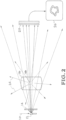
- Fig. 3 shows convergent imaging of an object whose spatial extent is small compared to the transverse dimension of the convergent x-ray beam.
- the pinhole is constructed from highly attenuating materials and is configured to have sufficient thickness so as to block any x-ray radiation not passing through the pinhole.
- the laser-Compton x-ray radiation that passes through the pinhole is collected by a conventional, 2-dimensional, x-ray detector system, e.g., x-ray film, an x-ray CCD.
- a conventional, 2-dimensional, x-ray detector system e.g., x-ray film, an x-ray CCD.
- the object is small compared to the beam diameter at the location at which it is placed. In this case an inverted shadowgraph of the full object is created at the detector array shown in Fig. 3 .
- the object is large compared to the laser-Compton beam diameter at the location at which it is placed. In this case, a complete image of the object is obtained by scanning the entire object and beam relative to each other with the beam direction and pinhole location fixed with respect to one another.
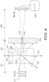
- FIG. 4 illustrates convergent imaging of a large object where a full 2D image is obtained by scanning the object relative to the x-ray beam axis. In both cases, scattered radiation and/or self-emission from the object are blocked from reaching the detector array and a high-quality, high-contrast radiograph is produced.
- FIG. 3 shows a quasi-mono-energetic, laser Compton x-ray beam 30 focused by a compound refractive x-ray lens 32 to a focal point 34.
- the beam 30 propagates through focal point 34 to the detector 36.
- Element 38 comprises a pinhole 39 co-located with focal point 34.
- the material and thickness of element 38 must be sufficient to prevent passage of the beam except through the pinhole aperture.
- the element is made of lead, or other highly attenuating material and has a thickness of greater than 10 micrometers.
- An object 40 is placed between the lens 32 and the focal point 34 of beam 30. This figure shows a feature 42 within object 40.
- Feature 42 is small compared to the transverse dimension of beam 30, i.e., the beam entirely covers feature 42.
- the figure shows a distance 44 from lens to object, a distance 46 from object to pinhole and a distance 48 that has been set for a desired magnification.
- X-ray self-emission/x-ray scatter 50 are produced when the beam propagates through the object. Only the portion of scatter 50 that passes through the pinhole will propagate onto the detector. This system produces a high contrast recorded image 52.
- FIG. 4 can be utilized when the feature to be imaged is large relative to the transverse dimension of the x-ray beam.
- This embodiment includes an object 60 with a feature 62 that is larger than the transverse dimension of the beam 30.
- the object can be scanned (moved) relative to the x-ray beam.
- a complete image of the object is obtained by scanning the entire object and beam relative to each other with the beam direction and pinhole location fixed with respect to one another.
- the arrow 64 signifies movement of the object in one direction relative to the beam and the arrow 66 signifies movement in the orthogonal direction to that of arrow 64.
- the image 68 is recoded at one position in the x-y scan of the object relative to the x-ray beam axis.
- Laser-Compton scattering (sometimes confusingly referred to as inverse Compton scattering) is the process in which an energetic laser pulse is scattered off of a short duration, bunch of relativistic electrons. This process has been recognized as a convenient method for production of short duration bursts of quasi-mono-energetic, x-ray radiation. When interacting with the electrons, the incident laser light induces a transverse motion on the electrons. The radiation from this motion when observed in the rest frame of the laboratory appears to be a forwardly directed, Doppler upshifted beam of high-energy photons.
- the highest energy of the laser-Compton source may be tuned, by changing the energy of the electron bunch and/or the energy of the laser photons. Beams of high-energy radiation ranging from few keV to > MeV have been produced by this process and used for a wide range of applications.
- Fig. 5 illustrates an angle correlated laser Compton spectrum. Photons from an energetic laser pulse 70 collide with relativistic electrons 72 to produce laser-Compton emission beam 74. In the transverse dimension of the beam 74, the highest energy laser-Compton photons are located in the central part 74' of the beam and the lower energy laser-Compton photons are located on the outer part 74" of the beam.
- the photon energy of the beam can be characterized as a continuum where the highest energy photons are along the central axis of the beam and the photon energy falls off with distance orthogonal to the central axis.
- an appropriately designed aperture such as aperture 76, placed in the path of the laser-Compton beam, one may create a quasi-mono-energetic x-ray or gamma-ray beam whose bandwidth ( ⁇ E/E) is 10%. Simulations indicate that on-axis bandwidths of order 0.1% can be obtained from properly designed laser-Compton systems.
- the high degree of collimation and quasi-mono-energetic character of laser-Compton x-ray sources is enabling to beam manipulation with a variety of x-ray optical technologies including but not limited to: compound refractive optics, capillary x-ray optics, x-ray zone plates, grazing incidence metal x-ray optics and grazing incidence multi-layer-coated x-ray optics.
- x-ray optical technologies including but not limited to: compound refractive optics, capillary x-ray optics, x-ray zone plates, grazing incidence metal x-ray optics and grazing incidence multi-layer-coated x-ray optics.
- the exact choice of optic will depend upon the energy of the x-rays desired for a particular imaging task. For the sake of providing an example, we will consider a laser-Compton beam with peak, on-axis, x-ray energy of 100 keV that is manipulated for convergent imaging and noise reduction by a compound refractive
- the index of refraction of all materials is less than unity and differs from unity by only a small amount.
- positive, refractive x-ray lenses have the shape of negative lenses in the visible portion of the spectrum, i.e., they are thinnest on axis and become thicker as one moves away from the optical axis. Because the index of materials is close to unity in the x-ray regime, a single x-ray refractive optic with a diameter matched to that of the laser-Compton beam would have very little optical power and thus very little influence on the natural divergence of the laser-Compton x-ray beam. See FIG. 6 .
- Compound refractive x-ray optics produce optical power by passing the x-ray beam along an optical axis (e.g., See FIG. 6 , optical axis 80) through a series of refractive elements (e.g., See FIG. 6 , single lens 82 and series of lenses 84). The sum of many weak lenses can produce sufficient optical power to collimate and/or focus a laser-Compton x-ray beam.
- Compound refractive x-ray optics have been developed, demonstrated, and utilized with synchrotron light sources to manipulate quasi-mono-energetic, synchrotron x-ray beams.
- Compound x-ray optics may be formed lithographically in solid wafer materials such as silicon or may be created by the stacking of coined metal discs each of which having a roughly parabolic shape.
- FIG. 6 is an image of compound refractive x-ray optics produced by lithography in Silicon.
- a one-dimensional focusing element is created in the material wafer and two-dimensional beam manipulation is produced by passing the full beam through two sets of optics oriented at 90 degrees with respect to one another.
- the quasi-mono-energetic nature of the laser-Compton source is well matched to compound optics whose transverse spatial profile is roughly parabolic.
- a compound x-ray refractive optic can be designed to either collimate the output and produce beams of a few 100 microns to a few millimeters in diameter or may be designed to focus the laser-Compton beam to a small spot.
- the size of the focal spot that can be produced will depend upon the focal length of the compound x-ray optic and the divergence properties of the laser-Compton x-ray beam that in turn depends upon the initial spot size of the laser and electron interaction of the laser-Compton source. Focused beams of a few microns are practical and focused beams of less than a micron are feasible.
- the converging x-ray beam produced by the combination of an appropriate laser-Compton x-ray source and x-ray optic may be used to create high-contrast, "background-free" images of an object in two ways.
- the object is small compared to the beam diameter at the location at which the object is placed. See FIG. 3 .
- the shadow of the object is produced in the converging beam. This is opposite to the conventional situation in which the x-ray shadow is produced in the diverging beam emanating from a bremsstrahlung source.
- an inverted shadow of the object is produced at the detector after the beam passes through its focus. Unwanted scatter or self-emission from the object is prevented from reaching the detector by placement of an optically thick pinhole at the position of the x-ray focus.
- the practical limitations of this mode of operation are the size of the x-ray optical assembly used to focus the laser-Compton beam and any spatial constraints that may exist due to the distance required for the laser-Compton beam to diverge to an appropriate size and distance required for the x-ray optic to focus the beam. Typically, these constraints limit the object size to millimeters or less.
- One practical medical application would be precision imaging of micron-scale capillary structures in angiographic procedures. The degree to which unwanted scatter from the object may be reduced from the image depends upon the distance from the object to the pinhole. For the example illustrated in FIG. 3 , at least 10 orders of magnitude reduction in wide-angle background is achievable.
- the object In the second mode of operation, the object is large compared to the beam diameter at the location at which the object is placed. See FIG. 4 .
- the shadow of only a portion of the object is produced in the converging beam and thus the object and beam must be scanned relative to one another in order to produce a full image of the object.
- the same reduction in scattered radiation impinging upon the detector is achievable as in the previous example and again provides a significant improvement in signal to noise at the detector.
- the laser-Compton beam is attenuated by absorption and scatter losses in the x-ray optic material.
- these losses may be up to 90% of the incident beam flux.
- this attenuation occurs before the object is illuminated and thus does not require increased exposure to the patient to improve image contrast.
- the convergent imaging geometry of this invention will expose the patient to a lower dose and for a given signal to noise at the detector (where noise is dominated by scattered radiation), the required dose to the patient may be orders of magnitude lower.
- this writing discloses at least the following: Techniques are provided for the production of high-contrast, x-ray and/or gamma-ray radiographic images.
- the images have minimal contributions from object-dependent background radiation.
- the invention utilizes the low divergence, quasi-monoenergetic, x-ray or gamma-ray output from a laser-Compton source in combination with x-ray optical technologies to produce a converging x-ray or gamma-ray beam with which to produce a high-contrast, shadowgraph of a specific object.
- the object to be imaged is placed within the path of the converging beam between the x-ray optical assembly and the focus of the x-ray beam produced by that assembly.
- the beam is then passed through an optically thick pinhole located at the focus of the beam. Downstream of the pinhole, the inverted shadowgraph of the object is then recorded by an appropriate 2D detector array.
Landscapes
- Health & Medical Sciences (AREA)
- Life Sciences & Earth Sciences (AREA)
- Engineering & Computer Science (AREA)
- Medical Informatics (AREA)
- Physics & Mathematics (AREA)
- General Health & Medical Sciences (AREA)
- High Energy & Nuclear Physics (AREA)
- Pathology (AREA)
- Optics & Photonics (AREA)
- Nuclear Medicine, Radiotherapy & Molecular Imaging (AREA)
- Radiology & Medical Imaging (AREA)
- Biomedical Technology (AREA)
- Heart & Thoracic Surgery (AREA)
- Molecular Biology (AREA)
- Surgery (AREA)
- Animal Behavior & Ethology (AREA)
- Biophysics (AREA)
- Public Health (AREA)
- Veterinary Medicine (AREA)
- Toxicology (AREA)
- Computer Vision & Pattern Recognition (AREA)
- Analytical Chemistry (AREA)
- Biochemistry (AREA)
- General Physics & Mathematics (AREA)
- Immunology (AREA)
- Chemical & Material Sciences (AREA)
- Spectroscopy & Molecular Physics (AREA)
- General Engineering & Computer Science (AREA)
- Analysing Materials By The Use Of Radiation (AREA)
- X-Ray Techniques (AREA)
- Apparatus For Radiation Diagnosis (AREA)
- Measurement Of Radiation (AREA)
Applications Claiming Priority (2)
| Application Number | Priority Date | Filing Date | Title |
|---|---|---|---|
| US201762539452P | 2017-07-31 | 2017-07-31 | |
| PCT/US2018/043342 WO2019027712A1 (en) | 2017-07-31 | 2018-07-23 | DEVICE AND METHOD FOR CONVERGENT X-RAY IMAGING |
Publications (4)
| Publication Number | Publication Date |
|---|---|
| EP3661421A1 EP3661421A1 (en) | 2020-06-10 |
| EP3661421A4 EP3661421A4 (en) | 2021-04-28 |
| EP3661421B1 true EP3661421B1 (en) | 2024-07-17 |
| EP3661421C0 EP3661421C0 (en) | 2024-07-17 |
Family
ID=65234182
Family Applications (1)
| Application Number | Title | Priority Date | Filing Date |
|---|---|---|---|
| EP18841917.0A Active EP3661421B1 (en) | 2017-07-31 | 2018-07-23 | Convergent x-ray imaging device and method |
Country Status (11)
| Country | Link |
|---|---|
| US (1) | US11357458B2 (enExample) |
| EP (1) | EP3661421B1 (enExample) |
| JP (1) | JP7252938B2 (enExample) |
| KR (1) | KR102675627B1 (enExample) |
| CN (1) | CN111065333B (enExample) |
| AU (1) | AU2018309611B2 (enExample) |
| CA (1) | CA3071142C (enExample) |
| ES (1) | ES2983741T3 (enExample) |
| PL (1) | PL3661421T3 (enExample) |
| WO (1) | WO2019027712A1 (enExample) |
| ZA (1) | ZA202000316B (enExample) |
Families Citing this family (5)
| Publication number | Priority date | Publication date | Assignee | Title |
|---|---|---|---|---|
| CN111065333B (zh) * | 2017-07-31 | 2024-04-16 | 劳伦斯·利弗莫尔国家安全有限责任公司 | 会聚x射线成像装置和方法 |
| US12066390B2 (en) * | 2020-08-04 | 2024-08-20 | Varex Imaging Corporation | Estimating background radiation from unknown sources |
| CN113984815B (zh) * | 2021-10-29 | 2023-09-05 | 北京师范大学 | 基于逆康普顿散射x光源的高效康普顿散射成像系统 |
| CN114068060B (zh) * | 2021-11-05 | 2024-11-22 | 中国科学院西安光学精密机械研究所 | 两个多层嵌套薄片结构对准系统及装调方法 |
| KR102762407B1 (ko) * | 2022-11-01 | 2025-02-05 | 한국원자력연구원 | 방사선을 이용한 오류 시험 장치 및 방법 |
Citations (1)
| Publication number | Priority date | Publication date | Assignee | Title |
|---|---|---|---|---|
| US20100316190A1 (en) * | 2009-06-12 | 2010-12-16 | Kevin Louis Baker | Phase-sensitive x-ray imager |
Family Cites Families (24)
| Publication number | Priority date | Publication date | Assignee | Title |
|---|---|---|---|---|
| JP2526409B2 (ja) * | 1994-02-18 | 1996-08-21 | 工業技術院長 | X線レンズ |
| JP3732568B2 (ja) | 1996-04-03 | 2006-01-05 | 株式会社東芝 | X線コンピュータ断層撮影装置 |
| US5805663A (en) * | 1997-05-08 | 1998-09-08 | Futec, Inc. | Radiation imaging method and system |
| WO2001006518A1 (en) * | 1999-07-19 | 2001-01-25 | Mamea Imaging Ab | A refractive x-ray arrangement |
| US6992313B2 (en) * | 2001-09-17 | 2006-01-31 | Adelphi Technology Inc. | X-ray and neutron imaging |
| GB0409572D0 (en) * | 2004-04-29 | 2004-06-02 | Univ Sheffield | High resolution imaging |
| US7964850B2 (en) | 2005-07-19 | 2011-06-21 | Milabs B.V. | Radiation detection apparatus |
| US20070121784A1 (en) * | 2005-09-20 | 2007-05-31 | Sectra Mamea Ab | X-ray imaging arrangement |
| US8045678B2 (en) * | 2008-03-21 | 2011-10-25 | Mxisystems, Inc. | Dynamically-varied beam energy using a tunable monochromatic X-ray beam |
| US7742574B2 (en) * | 2008-04-11 | 2010-06-22 | Mats Danielsson | Approach and device for focusing x-rays |
| US20150117599A1 (en) * | 2013-10-31 | 2015-04-30 | Sigray, Inc. | X-ray interferometric imaging system |
| US9412481B1 (en) | 2013-01-22 | 2016-08-09 | Michael Keith Fuller | Method and device for producing and using localized periodic intensity-modulated patterns with x-radiation and other wavelengths |
| EP2760028B1 (en) * | 2013-01-23 | 2018-12-12 | Samsung Electronics Co., Ltd | Radiation generator |
| US9364191B2 (en) * | 2013-02-11 | 2016-06-14 | University Of Rochester | Method and apparatus of spectral differential phase-contrast cone-beam CT and hybrid cone-beam CT |
| EP2818851B1 (en) * | 2013-06-26 | 2023-07-26 | Malvern Panalytical B.V. | Diffraction Imaging |
| WO2015019232A2 (en) * | 2013-08-08 | 2015-02-12 | Controlrad Systems Inc. | X-ray reduction system |
| ES2815376T3 (es) * | 2014-05-08 | 2021-03-29 | L Livermore Nat Security Llc | Procedimientos para radiografía de 2 colores con fuentes de rayos X generados por láser mediante el efecto Compton |
| US10401309B2 (en) * | 2014-05-15 | 2019-09-03 | Sigray, Inc. | X-ray techniques using structured illumination |
| WO2016030205A1 (en) * | 2014-08-28 | 2016-03-03 | Vrije Universiteit Amsterdam | Inspection apparatus, inspection method and manufacturing method |
| GB201421837D0 (en) * | 2014-12-09 | 2015-01-21 | Reishig Peter | A method of generating a fingerprint for a gemstone using X-ray imaging |
| CN104931481B (zh) * | 2015-06-23 | 2017-08-25 | 北京理工大学 | 激光双轴差动共焦诱导击穿‑拉曼光谱成像探测方法与装置 |
| US10757795B2 (en) * | 2015-10-06 | 2020-08-25 | Koninklijke Philips N.V. | Device for determining spatially dependent x-ray flux degradation and photon spectral change |
| WO2017157645A1 (en) * | 2016-03-15 | 2017-09-21 | Stichting Vu | Inspection method, inspection apparatus and illumination method and apparatus |
| CN111065333B (zh) * | 2017-07-31 | 2024-04-16 | 劳伦斯·利弗莫尔国家安全有限责任公司 | 会聚x射线成像装置和方法 |
-
2018
- 2018-07-23 CN CN201880049566.XA patent/CN111065333B/zh active Active
- 2018-07-23 JP JP2020503326A patent/JP7252938B2/ja active Active
- 2018-07-23 ES ES18841917T patent/ES2983741T3/es active Active
- 2018-07-23 KR KR1020207002407A patent/KR102675627B1/ko active Active
- 2018-07-23 US US16/635,128 patent/US11357458B2/en active Active
- 2018-07-23 CA CA3071142A patent/CA3071142C/en active Active
- 2018-07-23 WO PCT/US2018/043342 patent/WO2019027712A1/en not_active Ceased
- 2018-07-23 AU AU2018309611A patent/AU2018309611B2/en active Active
- 2018-07-23 PL PL18841917.0T patent/PL3661421T3/pl unknown
- 2018-07-23 EP EP18841917.0A patent/EP3661421B1/en active Active
-
2020
- 2020-01-16 ZA ZA2020/00316A patent/ZA202000316B/en unknown
Patent Citations (1)
| Publication number | Priority date | Publication date | Assignee | Title |
|---|---|---|---|---|
| US20100316190A1 (en) * | 2009-06-12 | 2010-12-16 | Kevin Louis Baker | Phase-sensitive x-ray imager |
Also Published As
| Publication number | Publication date |
|---|---|
| NZ760906A (en) | 2025-06-27 |
| AU2018309611A1 (en) | 2020-02-13 |
| AU2018309611B2 (en) | 2022-11-10 |
| ZA202000316B (en) | 2024-06-26 |
| JP7252938B2 (ja) | 2023-04-05 |
| KR102675627B1 (ko) | 2024-06-18 |
| EP3661421A1 (en) | 2020-06-10 |
| KR20200027516A (ko) | 2020-03-12 |
| CN111065333A (zh) | 2020-04-24 |
| CA3071142C (en) | 2023-08-22 |
| US11357458B2 (en) | 2022-06-14 |
| EP3661421A4 (en) | 2021-04-28 |
| PL3661421T3 (pl) | 2024-11-18 |
| EP3661421C0 (en) | 2024-07-17 |
| ES2983741T3 (es) | 2024-10-24 |
| JP2020530107A (ja) | 2020-10-15 |
| WO2019027712A1 (en) | 2019-02-07 |
| CA3071142A1 (en) | 2019-02-07 |
| CN111065333B (zh) | 2024-04-16 |
| US20200261042A1 (en) | 2020-08-20 |
Similar Documents
| Publication | Publication Date | Title |
|---|---|---|
| EP3661421B1 (en) | Convergent x-ray imaging device and method | |
| Perry et al. | Hard x-ray production from high intensity laser solid interactions | |
| US8073099B2 (en) | Differential interference phase contrast X-ray imaging system | |
| US6389101B1 (en) | Parallel x-ray nanotomography | |
| WO1992008235A1 (en) | Device for controlling beams of particles, x-ray and gamma quanta and uses thereof | |
| Underwood et al. | Development of control mechanisms for a laser wakefield accelerator-driven bremsstrahlung x-ray source for advanced radiographic imaging | |
| Khan et al. | A dual high-energy radiography platform with 15 μm resolution at the National Ignition Facility | |
| EP0556901B1 (en) | Apparatus for detecting high energy radiation | |
| Rusby et al. | Diagnostic development and needs for laser driven MeV x-ray radiography | |
| HK40022739B (en) | Convergent x-ray imaging device and method | |
| HK40022739A (en) | Convergent x-ray imaging device and method | |
| JP6108671B2 (ja) | 放射線撮影装置 | |
| US12419595B2 (en) | Backscattered x-photon imaging device | |
| Kumakhov | Status of x-ray capillary optics | |
| Kumakhov | State and perspectives of capillary Roentgen optics | |
| VanDervort et al. | Development of a backlit-multi-pinhole radiography source | |
| Ambrosi et al. | A large area fast neutron detector based on an amorphous silicon pixel array and reflective telescope optics | |
| US20100158196A1 (en) | Radiation beam blocker with non-cylindrical through-hole causing reduced geometric unsharpness in radiographic image, and method for the preparation thereof | |
| Sinars et al. | 1-to 10-keV x-ray backlighting of annular wire arrays on the Sandia Z-machine using bent-crystal imaging techniques | |
| Tsipenyuk | Poly-capillary X-ray and neutron optics (Kumakhov optics) | |
| Eagleton et al. | Target diagnostics for commissioning the AWE HELEN Laser Facility 100TW chirped pulse amplification beam | |
| JP2013171630A (ja) | X線発生装置 | |
| Freeman | Radiation patterns from electron beam fusion targets | |
| NZ760906B2 (en) | Convergent x-ray imaging device and method | |
| Umland | Some Facts about X-Rays |
Legal Events
| Date | Code | Title | Description |
|---|---|---|---|
| STAA | Information on the status of an ep patent application or granted ep patent |
Free format text: STATUS: THE INTERNATIONAL PUBLICATION HAS BEEN MADE |
|
| PUAI | Public reference made under article 153(3) epc to a published international application that has entered the european phase |
Free format text: ORIGINAL CODE: 0009012 |
|
| STAA | Information on the status of an ep patent application or granted ep patent |
Free format text: STATUS: REQUEST FOR EXAMINATION WAS MADE |
|
| 17P | Request for examination filed |
Effective date: 20200204 |
|
| AK | Designated contracting states |
Kind code of ref document: A1 Designated state(s): AL AT BE BG CH CY CZ DE DK EE ES FI FR GB GR HR HU IE IS IT LI LT LU LV MC MK MT NL NO PL PT RO RS SE SI SK SM TR |
|
| AX | Request for extension of the european patent |
Extension state: BA ME |
|
| DAV | Request for validation of the european patent (deleted) | ||
| DAX | Request for extension of the european patent (deleted) | ||
| REG | Reference to a national code |
Ref country code: HK Ref legal event code: DE Ref document number: 40022739 Country of ref document: HK |
|
| A4 | Supplementary search report drawn up and despatched |
Effective date: 20210325 |
|
| RIC1 | Information provided on ipc code assigned before grant |
Ipc: A61B 6/00 20060101AFI20210322BHEP Ipc: A61B 6/06 20060101ALI20210322BHEP Ipc: G01N 23/02 20060101ALI20210322BHEP Ipc: G01N 23/223 20060101ALI20210322BHEP Ipc: G02B 27/46 20060101ALI20210322BHEP Ipc: H05H 9/00 20060101ALI20210322BHEP |
|
| STAA | Information on the status of an ep patent application or granted ep patent |
Free format text: STATUS: EXAMINATION IS IN PROGRESS |
|
| 17Q | First examination report despatched |
Effective date: 20220718 |
|
| GRAP | Despatch of communication of intention to grant a patent |
Free format text: ORIGINAL CODE: EPIDOSNIGR1 |
|
| STAA | Information on the status of an ep patent application or granted ep patent |
Free format text: STATUS: GRANT OF PATENT IS INTENDED |
|
| INTG | Intention to grant announced |
Effective date: 20231121 |
|
| GRAJ | Information related to disapproval of communication of intention to grant by the applicant or resumption of examination proceedings by the epo deleted |
Free format text: ORIGINAL CODE: EPIDOSDIGR1 |
|
| STAA | Information on the status of an ep patent application or granted ep patent |
Free format text: STATUS: EXAMINATION IS IN PROGRESS |
|
| GRAP | Despatch of communication of intention to grant a patent |
Free format text: ORIGINAL CODE: EPIDOSNIGR1 |
|
| STAA | Information on the status of an ep patent application or granted ep patent |
Free format text: STATUS: GRANT OF PATENT IS INTENDED |
|
| INTC | Intention to grant announced (deleted) | ||
| INTG | Intention to grant announced |
Effective date: 20240220 |
|
| GRAS | Grant fee paid |
Free format text: ORIGINAL CODE: EPIDOSNIGR3 |
|
| GRAA | (expected) grant |
Free format text: ORIGINAL CODE: 0009210 |
|
| STAA | Information on the status of an ep patent application or granted ep patent |
Free format text: STATUS: THE PATENT HAS BEEN GRANTED |
|
| AK | Designated contracting states |
Kind code of ref document: B1 Designated state(s): AL AT BE BG CH CY CZ DE DK EE ES FI FR GB GR HR HU IE IS IT LI LT LU LV MC MK MT NL NO PL PT RO RS SE SI SK SM TR |
|
| REG | Reference to a national code |
Ref country code: CH Ref legal event code: EP |
|
| REG | Reference to a national code |
Ref country code: DE Ref legal event code: R096 Ref document number: 602018071968 Country of ref document: DE |
|
| REG | Reference to a national code |
Ref country code: IE Ref legal event code: FG4D |
|
| U01 | Request for unitary effect filed |
Effective date: 20240719 |
|
| U07 | Unitary effect registered |
Designated state(s): AT BE BG DE DK EE FI FR IT LT LU LV MT NL PT SE SI Effective date: 20240801 |
|
| U20 | Renewal fee for the european patent with unitary effect paid |
Year of fee payment: 7 Effective date: 20240820 |
|
| REG | Reference to a national code |
Ref country code: ES Ref legal event code: FG2A Ref document number: 2983741 Country of ref document: ES Kind code of ref document: T3 Effective date: 20241024 |
|
| PG25 | Lapsed in a contracting state [announced via postgrant information from national office to epo] |
Ref country code: GR Free format text: LAPSE BECAUSE OF FAILURE TO SUBMIT A TRANSLATION OF THE DESCRIPTION OR TO PAY THE FEE WITHIN THE PRESCRIBED TIME-LIMIT Effective date: 20241018 |
|
| PG25 | Lapsed in a contracting state [announced via postgrant information from national office to epo] |
Ref country code: IS Free format text: LAPSE BECAUSE OF FAILURE TO SUBMIT A TRANSLATION OF THE DESCRIPTION OR TO PAY THE FEE WITHIN THE PRESCRIBED TIME-LIMIT Effective date: 20241117 |
|
| PG25 | Lapsed in a contracting state [announced via postgrant information from national office to epo] |
Ref country code: HR Free format text: LAPSE BECAUSE OF FAILURE TO SUBMIT A TRANSLATION OF THE DESCRIPTION OR TO PAY THE FEE WITHIN THE PRESCRIBED TIME-LIMIT Effective date: 20240717 |
|
| PG25 | Lapsed in a contracting state [announced via postgrant information from national office to epo] |
Ref country code: RS Free format text: LAPSE BECAUSE OF FAILURE TO SUBMIT A TRANSLATION OF THE DESCRIPTION OR TO PAY THE FEE WITHIN THE PRESCRIBED TIME-LIMIT Effective date: 20241017 |
|
| PG25 | Lapsed in a contracting state [announced via postgrant information from national office to epo] |
Ref country code: RS Free format text: LAPSE BECAUSE OF FAILURE TO SUBMIT A TRANSLATION OF THE DESCRIPTION OR TO PAY THE FEE WITHIN THE PRESCRIBED TIME-LIMIT Effective date: 20241017 Ref country code: IS Free format text: LAPSE BECAUSE OF FAILURE TO SUBMIT A TRANSLATION OF THE DESCRIPTION OR TO PAY THE FEE WITHIN THE PRESCRIBED TIME-LIMIT Effective date: 20241117 Ref country code: HR Free format text: LAPSE BECAUSE OF FAILURE TO SUBMIT A TRANSLATION OF THE DESCRIPTION OR TO PAY THE FEE WITHIN THE PRESCRIBED TIME-LIMIT Effective date: 20240717 Ref country code: GR Free format text: LAPSE BECAUSE OF FAILURE TO SUBMIT A TRANSLATION OF THE DESCRIPTION OR TO PAY THE FEE WITHIN THE PRESCRIBED TIME-LIMIT Effective date: 20241018 |
|
| PG25 | Lapsed in a contracting state [announced via postgrant information from national office to epo] |
Ref country code: SM Free format text: LAPSE BECAUSE OF FAILURE TO SUBMIT A TRANSLATION OF THE DESCRIPTION OR TO PAY THE FEE WITHIN THE PRESCRIBED TIME-LIMIT Effective date: 20240717 |
|
| PG25 | Lapsed in a contracting state [announced via postgrant information from national office to epo] |
Ref country code: MC Free format text: LAPSE BECAUSE OF FAILURE TO SUBMIT A TRANSLATION OF THE DESCRIPTION OR TO PAY THE FEE WITHIN THE PRESCRIBED TIME-LIMIT Effective date: 20240717 |
|
| PG25 | Lapsed in a contracting state [announced via postgrant information from national office to epo] |
Ref country code: CZ Free format text: LAPSE BECAUSE OF FAILURE TO SUBMIT A TRANSLATION OF THE DESCRIPTION OR TO PAY THE FEE WITHIN THE PRESCRIBED TIME-LIMIT Effective date: 20240717 |
|
| PG25 | Lapsed in a contracting state [announced via postgrant information from national office to epo] |
Ref country code: SK Free format text: LAPSE BECAUSE OF FAILURE TO SUBMIT A TRANSLATION OF THE DESCRIPTION OR TO PAY THE FEE WITHIN THE PRESCRIBED TIME-LIMIT Effective date: 20240717 |
|
| PLBE | No opposition filed within time limit |
Free format text: ORIGINAL CODE: 0009261 |
|
| STAA | Information on the status of an ep patent application or granted ep patent |
Free format text: STATUS: NO OPPOSITION FILED WITHIN TIME LIMIT |
|
| 26N | No opposition filed |
Effective date: 20250422 |
|
| PG25 | Lapsed in a contracting state [announced via postgrant information from national office to epo] |
Ref country code: IE Free format text: LAPSE BECAUSE OF NON-PAYMENT OF DUE FEES Effective date: 20240723 |
|
| U20 | Renewal fee for the european patent with unitary effect paid |
Year of fee payment: 8 Effective date: 20250728 |
|
| PGFP | Annual fee paid to national office [announced via postgrant information from national office to epo] |
Ref country code: ES Payment date: 20250801 Year of fee payment: 8 |
|
| PGFP | Annual fee paid to national office [announced via postgrant information from national office to epo] |
Ref country code: NO Payment date: 20250729 Year of fee payment: 8 |
|
| PGFP | Annual fee paid to national office [announced via postgrant information from national office to epo] |
Ref country code: PL Payment date: 20250701 Year of fee payment: 8 |
|
| PGFP | Annual fee paid to national office [announced via postgrant information from national office to epo] |
Ref country code: GB Payment date: 20250728 Year of fee payment: 8 |
|
| PGFP | Annual fee paid to national office [announced via postgrant information from national office to epo] |
Ref country code: CH Payment date: 20250801 Year of fee payment: 8 |
|
| PGFP | Annual fee paid to national office [announced via postgrant information from national office to epo] |
Ref country code: RO Payment date: 20250707 Year of fee payment: 8 |
|
| U1N | Appointed representative for the unitary patent procedure changed after the registration of the unitary effect |
Representative=s name: LUSINCHI, LAURENT PIERRE; GB |
|
| PG25 | Lapsed in a contracting state [announced via postgrant information from national office to epo] |
Ref country code: CY Free format text: LAPSE BECAUSE OF FAILURE TO SUBMIT A TRANSLATION OF THE DESCRIPTION OR TO PAY THE FEE WITHIN THE PRESCRIBED TIME-LIMIT; INVALID AB INITIO Effective date: 20180723 |
|
| PG25 | Lapsed in a contracting state [announced via postgrant information from national office to epo] |
Ref country code: HU Free format text: LAPSE BECAUSE OF FAILURE TO SUBMIT A TRANSLATION OF THE DESCRIPTION OR TO PAY THE FEE WITHIN THE PRESCRIBED TIME-LIMIT; INVALID AB INITIO Effective date: 20180723 |