EP3661383B1 - Zur integration in schuhsohlen geeignete vorrichtung, die als polsterungs-, energieableitungs- und stabilisierungsmittel wirkt - Google Patents
Zur integration in schuhsohlen geeignete vorrichtung, die als polsterungs-, energieableitungs- und stabilisierungsmittel wirkt Download PDFInfo
- Publication number
- EP3661383B1 EP3661383B1 EP18759409.8A EP18759409A EP3661383B1 EP 3661383 B1 EP3661383 B1 EP 3661383B1 EP 18759409 A EP18759409 A EP 18759409A EP 3661383 B1 EP3661383 B1 EP 3661383B1
- Authority
- EP
- European Patent Office
- Prior art keywords
- cushioning
- protrusions
- regions
- acting
- region
- Prior art date
- Legal status (The legal status is an assumption and is not a legal conclusion. Google has not performed a legal analysis and makes no representation as to the accuracy of the status listed.)
- Active
Links
Images






Classifications
-
- A—HUMAN NECESSITIES
- A43—FOOTWEAR
- A43B—CHARACTERISTIC FEATURES OF FOOTWEAR; PARTS OF FOOTWEAR
- A43B13/00—Soles; Sole-and-heel integral units
- A43B13/14—Soles; Sole-and-heel integral units characterised by the constructive form
- A43B13/18—Resilient soles
- A43B13/181—Resiliency achieved by the structure of the sole
- A43B13/186—Differential cushioning region, e.g. cushioning located under the ball of the foot
-
- A—HUMAN NECESSITIES
- A43—FOOTWEAR
- A43B—CHARACTERISTIC FEATURES OF FOOTWEAR; PARTS OF FOOTWEAR
- A43B7/00—Footwear with health or hygienic arrangements
- A43B7/14—Footwear with health or hygienic arrangements with foot-supporting parts
- A43B7/1405—Footwear with health or hygienic arrangements with foot-supporting parts with pads or holes on one or more locations, or having an anatomical or curved form
- A43B7/1415—Footwear with health or hygienic arrangements with foot-supporting parts with pads or holes on one or more locations, or having an anatomical or curved form characterised by the location under the foot
- A43B7/144—Footwear with health or hygienic arrangements with foot-supporting parts with pads or holes on one or more locations, or having an anatomical or curved form characterised by the location under the foot situated under the heel, i.e. the calcaneus bone
-
- A—HUMAN NECESSITIES
- A43—FOOTWEAR
- A43B—CHARACTERISTIC FEATURES OF FOOTWEAR; PARTS OF FOOTWEAR
- A43B13/00—Soles; Sole-and-heel integral units
- A43B13/02—Soles; Sole-and-heel integral units characterised by the material
- A43B13/12—Soles with several layers of different materials
-
- A—HUMAN NECESSITIES
- A43—FOOTWEAR
- A43B—CHARACTERISTIC FEATURES OF FOOTWEAR; PARTS OF FOOTWEAR
- A43B13/00—Soles; Sole-and-heel integral units
- A43B13/02—Soles; Sole-and-heel integral units characterised by the material
- A43B13/12—Soles with several layers of different materials
- A43B13/125—Soles with several layers of different materials characterised by the midsole or middle layer
-
- A—HUMAN NECESSITIES
- A43—FOOTWEAR
- A43B—CHARACTERISTIC FEATURES OF FOOTWEAR; PARTS OF FOOTWEAR
- A43B13/00—Soles; Sole-and-heel integral units
- A43B13/14—Soles; Sole-and-heel integral units characterised by the constructive form
- A43B13/18—Resilient soles
- A43B13/187—Resiliency achieved by the features of the material, e.g. foam, non liquid materials
- A43B13/188—Differential cushioning regions
-
- A—HUMAN NECESSITIES
- A43—FOOTWEAR
- A43B—CHARACTERISTIC FEATURES OF FOOTWEAR; PARTS OF FOOTWEAR
- A43B21/00—Heels; Top-pieces or top-lifts
- A43B21/24—Heels; Top-pieces or top-lifts characterised by the constructive form
- A43B21/26—Resilient heels
-
- A—HUMAN NECESSITIES
- A43—FOOTWEAR
- A43B—CHARACTERISTIC FEATURES OF FOOTWEAR; PARTS OF FOOTWEAR
- A43B21/00—Heels; Top-pieces or top-lifts
- A43B21/24—Heels; Top-pieces or top-lifts characterised by the constructive form
- A43B21/32—Resilient supports for the heel of the foot
-
- A—HUMAN NECESSITIES
- A43—FOOTWEAR
- A43B—CHARACTERISTIC FEATURES OF FOOTWEAR; PARTS OF FOOTWEAR
- A43B7/00—Footwear with health or hygienic arrangements
- A43B7/06—Footwear with health or hygienic arrangements ventilated
-
- A—HUMAN NECESSITIES
- A43—FOOTWEAR
- A43B—CHARACTERISTIC FEATURES OF FOOTWEAR; PARTS OF FOOTWEAR
- A43B7/00—Footwear with health or hygienic arrangements
- A43B7/14—Footwear with health or hygienic arrangements with foot-supporting parts
- A43B7/1405—Footwear with health or hygienic arrangements with foot-supporting parts with pads or holes on one or more locations, or having an anatomical or curved form
- A43B7/1475—Footwear with health or hygienic arrangements with foot-supporting parts with pads or holes on one or more locations, or having an anatomical or curved form characterised by the type of support
- A43B7/148—Recesses or holes filled with supports or pads
-
- A—HUMAN NECESSITIES
- A43—FOOTWEAR
- A43B—CHARACTERISTIC FEATURES OF FOOTWEAR; PARTS OF FOOTWEAR
- A43B7/00—Footwear with health or hygienic arrangements
- A43B7/14—Footwear with health or hygienic arrangements with foot-supporting parts
- A43B7/1405—Footwear with health or hygienic arrangements with foot-supporting parts with pads or holes on one or more locations, or having an anatomical or curved form
- A43B7/1475—Footwear with health or hygienic arrangements with foot-supporting parts with pads or holes on one or more locations, or having an anatomical or curved form characterised by the type of support
- A43B7/1485—Recesses or holes, traversing partially or completely the thickness of the pad
-
- A—HUMAN NECESSITIES
- A43—FOOTWEAR
- A43B—CHARACTERISTIC FEATURES OF FOOTWEAR; PARTS OF FOOTWEAR
- A43B7/00—Footwear with health or hygienic arrangements
- A43B7/14—Footwear with health or hygienic arrangements with foot-supporting parts
- A43B7/1405—Footwear with health or hygienic arrangements with foot-supporting parts with pads or holes on one or more locations, or having an anatomical or curved form
- A43B7/1475—Footwear with health or hygienic arrangements with foot-supporting parts with pads or holes on one or more locations, or having an anatomical or curved form characterised by the type of support
- A43B7/149—Pads, e.g. protruding on the foot-facing surface
Definitions
- the present invention relates to a device suitable for being integrated in footwears soles, acting as cushioning, energy dissipation and stabilization means.
- a footwear is made of two main elements: the upper and the sole.
- the upper that is the upper part of the shoe, is specifically designed to wrap the foot in an ergonomic and comfortable way, while the sole, the part on which the sole of the foot lies, is designed to cushion and stabilize the walk.
- the same sole is typically made of a light, soft and flexible midsole made of an expanded material, and of a more compact tread able to assure a greater resistance to abrasion and a suitable friction with the ground.
- the reaction force is, only partially, diminished by the human body through a three-dimensional complex movement of the foot comprised between the area of the heel and the metatarsal, while the remaining part is transmitted at first to the heel, then to the ankles, to the knees, to the pelvis and then, little by little, along the vertebral column up until the cervical area.
- Such an intense reaction force if not adequately softened through a sole with cushioning characteristics, can cause serious damages to the tendinous and musculoskeletal structures of the user.
- An evolution of the aforementioned footwears with a midsole made of EVA is that of soles with specific cushioning devices, such as systems with springs or elements made of a thermoplastic material with a gel effect, with an air cushion or an encapsulated liquid.
- the patent US4934072 describes a solution achieved through a bearing positioned in the area of the heel, made of a sealed element divided in two chambers, one containing a mixture of viscous liquids and the other containing gas.
- the patent US4815221 describes a solution achieved through a cushioning system made with strings, positioned in the area of the heel.
- the patent US4342157 describes a solution achieved through the insertion of cushioning elements with an encapsulated liquid such as water, glycerin or mineral oil, positioned in the bottom of the midsole in the area of the heel and the metatarsal heads.
- an encapsulated liquid such as water, glycerin or mineral oil
- the patent US7000335 describes a solution that considers the insertion of a cushioning element in the area of the heel, achieved through an encapsulated fluid.
- an example of a cushioning sole alternative to that with a midsole made of EP is the sole realized inserting a big portion made of expanded thermoplastic polyurethane (E-TPU) in the area of the heel, right under the assembly insole.
- E-TPU expanded thermoplastic polyurethane
- the known portion is made of a material commercially known as "Infinergy", made by BASF for the athletic field. This hyperelastic material has been tested in compliance with the ISO 8307 standard (sphere bounce test) and DIN 53512 standard (palymbalometer test).
- the phase that comes first the "heel off”, that is the moment preempting the detachment of the heel from the ground, turns out to be as critical as the support phase of the heel to the ground called “heel strike”.
- the sole should react to the reduction of the load with a modulated push depending on the weight, which helps and accompanies the lifting of the heel gradually.
- An impulse-type reaction in this phase could, instead, cause micro-traumas to the tendinous and musculoskeletal structures, thus being injurious to the user.
- the cushioning element is made of a thermoplastic material with an elastic effect, very soft, inserted under the plantar and wedged in a hole formed in the insole and in the polyurethane sole. Its shape is pear-shaped, similar in size to Arbesko's product. Unlike the latter, the product of Steitz is available in four variants, each of them being characterized by a more or less yielding material, depending on the user's body weight.
- a not negligible aspect is the flexibility of this kind of materials which, showing a distinctly elastic reaction, act with an impulsive force, proportional to the amount of the absorbed energy.
- the sole includes a midsole that absorbs force and a flexible wear resistant sole.
- the midsole including at least a cushioning element made of a viscoelastic material (gel type, preferably silicone), and a conditioning element of the cushioning element, on which is placed the cushioning element.
- the sole includes a cartridge cushioning system that includes a plate that distributes the load and deformation elements placed in an area of the sole forefoot in order to provide support and/or cushioning to the forefoot.
- the shoe sole can include a second cartridge cushioning system which includes a second plate for the deformation of the load and functional elements placed in an area of the heel of the sole in order to drive the foot in a neutral position after the first contact with the ground.
- the shock absorbing elements include a plurality of receptacles extending from the lower plate and a plurality of protrusions extending from the upper plate. Each protrusion is associated with one receptacle, and a portion of each protrusion extends into the receptacle. A resilient sleeve surrounds each associated protrusion and receptacle.
- a plurality of shock absorbing elements extends from a bridge on one of the upper and lower plates.
- the purpose of the present invention is to provide a device suitable for being integrated in footwears soles, acting as cushioning, energy dissipation and stabilization means and allowing the efficient discharge of the air from the shoes during the compression by a user.
- the purpose of the present invention having geometrical and mechanical features so as to obtain a different kind of reaction depending on the amount of the load it is subjected to, allowing an optimized mechanical behavior and a distribution of loads and stresses, so as to be practical, comfortable and functional both with the user standing still and while walking or making a jump, therefore having characteristics such as to overcome the limits which still affect the known systems for cushioning, energy dissipation and stabilization.
- a device suitable for being integrated in footwears soles, acting as cushioning, energy dissipation and stabilization means is provided, as defined in claim 1.
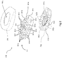
- a device 200 suitable for being integrated in footwears soles, acting as cushioning, energy dissipation and stabilization means is shown.
- the device 200, 300 suitable for being integrated in footwears soles, acting as cushioning, energy dissipation and stabilization means, as shown in figures 1 and 4 is a modular device comprising a cushioning element 201, 301, made of a first material having a viscoelastic behavior, positioned over a conditioning element 202, 302 of the cushioning element 201, 301.
- the conditioning element 202, 302 is made of a second material having a viscoelastic behavior, and more rigid than the first material having a viscoelastic behavior of which the cushioning element 201, 301 is made.
- the device 300 also comprises a containing element 303 positioned above the cushioning element 301 and covering also the conditioning element 302.
- the device 200, 300 is formed by the non-hermetic coupling between the cushioning element 201, 301, the conditioning element 202, 302 and the containing element 203, 303 such as to allow the spill of the air contained in predefined interstices, for example a plurality of holes 201g, 201h and channels 201i, included between the cushioning elements 201, 301, the conditioning elements 202, 302 when the device 200, 300 is subjected to a compression load, in use.
- predefined interstices for example a plurality of holes 201g, 201h and channels 201i, included between the cushioning elements 201, 301, the conditioning elements 202, 302 when the device 200, 300 is subjected to a compression load, in use.
- the air present in the interstices at rest when in use the device is subjected to a compressive stress due, for example, to the walk of a user, pours out from the plurality of holes 201g, 201h, 301f, 301c, and channels 201i, 301i formed in the cushioning element 201, 301 and in the conditioning element 202, 302.
- this plurality of holes and channels and the non-hermetic coupling between the elements allows the device 200, 300 to have a controlled and not influenced by the presence of air mechanical response to the compressive stresses.
- the conditioning element 302 is made of a flexible material but with not negligible features of stiffness.
- the containing element 303 is made of a flexible material but with not negligible features of stiffness.
- the conditioning element 202, 302 and the containing element 203, 303 are made of a material chosen among: Polyurethane, rubber, TPU (thermoplastic polyurethane), EVA (ethylene vinyl acetate), polypropylene and other materials that are suitable for the functioning.
- non-hermetic coupling between the elements allows the device 200, 300 to cause air to come out and, therefore, to have a controlled mechanical response to compressive stresses, not influenced by the presence of air.
- This non-hermetic coupling is achieved through a pre-defined alternation of regions full of the aforementioned material and of regions empty the same material, which are substantially hollow and, therefore, empty.
- the cushioning element 201 and 301 consists of a structure that comprises a pre-defined alternation of first regions full of the first viscoelastic material and of first regions empty of the first viscoelastic material, able to couple with a corresponding pre-defined alternation of second regions empty of the second viscoelastic material and of second regions full of the second viscoelastic material, or protrusions, of the conditioning element 202 and 302, when the device 200, 300 is subjected to a compression load.
- second empty regions of conditioning element 302 are a plurality of second holes 301h and channels 301i that allow the cushioning element 301 to be deformed and adapted in a controlled manner. There are also second holes and smaller channels, able to spill the air contained inside the device, when it is subjected to a compression force.
- the conditioning element 302 comprises peripheral upper protrusions having different heights for a differentiated support, to act as a support.
- the surfaces of the peripheral upper protrusions are sloped, creating a central concave surface configured to react to the application of an external load force and to straight foot toward the center of the heel, allowing the device to react to a load application with a centripetal reaction force able to align back any decentralized loads with respect to the center of the heel.
- the cushioning elements 301, conditioning elements 302 and containing elements 303 have a substantially oval shape.
- containing element 303 has a concave surface which follows a heel's curvature and, together with the conditioning element, defines a volume within which the cushioning element can warp.
- the containing element 203 has a central ventilation hole 203a and the cushioning element 201 has a central protrusion 201a able to be coupled to the central hole 203a.
- the central hole 203a of the containing element 203 increases the user's comfort perception and facilitate the discharge of the air during the use.
- the same function of the containing element 203 can be carried out directly by the midsole of the shoe.
- conditioning elements 302 and containing elements 303 influence the mechanical behavior of element 201, 301 by means of a pre-defined succession of full material portions and empty portions, as holes and channels, conveniently balanced.
- the materials of the cushioning element 301, of the conditioning element 302 and of the containing element 303 and their shape allow the device 300 to have an "active" operation mode, that is to be able to obtain a different reaction response in function of the load amount to which it is subjected.
- This active operation mode caused by the shape and the materials of the device 300, prevent the incurring of sprains, twist and injuries.
- the device 300 is therefore different from the state of the art, describing mentioned 'passive' systems, that is systems able to absorb energy by means exclusively of chemical-physical characteristics of the material.
- Known devices and systems also have a rheologic behavior that cannot be modulated in a controlled manner with the changing of the load.
- the cushioning element 301 is made of a material having a high elastic deformation capacity and it is configured to be positioned in the area under the heel of the user. In this way, the cushioning element 301 enhances the energy absorbing characteristics of the device 300 during loading ("heel strike"), so as to amortize and slow down the impact velocity between the user's heel and the soil.
- the cushioning element 301 is made of a material having a rheological behavior that has a delay in the response to a load variation. Therefore, during the phase preceding the "Heel off" moment, i.e. the instant preceding the detachment of the heel, the device 300 is able to gradually return the energy absorbed and generate a biomechanically compatible thrust that is comfortable, anti-fatigue and above all not harmful to the user's tendon and musculoskeletal structure.
- the holes and channels formed in the conditioning element 302 and in the containing element 303 facilitate the air eventually comprised in interstice spaces to spill out.
- Another function of said holes and channels is to allow the cushioning element 301 to deform, also thanks to empty regions, that act as expansion positions of cushioning element and that characterizes the shape and geometry of the device, highly increasing the energy dissipation capacity of the device 300. Indeed, only a part of the energy absorbed during the loading phase will be transmitted to the user during the unloading phase, or in the phase preceding the detachment of the heel, in the form of a thrust that facilitates the lifting of the heel ("heel off”) in a biomechanically compatible manner.
- the conditioning element 302 is made of a second viscoelastic material, more compact than other elements, and its shape, together with the containment function of containment element 303, is configured to make all the reaction forces converge at a same point. In this way the heel is always brought in axis along the tibia/fibula direction, whatever the direction of the applied stress is (pronation or supination).
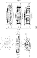
- Figure 4 shows a cross section, for example, of device 200 but the same applies to device 300, before the application of the load ( Fig. 4A ) and after the application of the load (Fig. 4B) .
- the device 200 Before the application of the load ( Fig. 4A ) the device 200 is not compressed; elements 202 and 203 define a volume within which the cushioning element 201 can deform.
- arrows identify the deformation directions of the cushioning element 201.
- a compression load F is applied to the device 200 (Fig. 4B) ; the cushioning element 201 deforms according to the directions indicated in figure 4A , until the shape of the cushioning 201 is defined by components 202 and 203 jointly.
- Arrows in figure 4B indicate the direction of reaction forces of the device 200 upon application of the load. Thanks to the geometry and shape of elements 202 and 203, the reaction forces converge towards a single point, acting so as to bring back any loads off-centered with respect to the heel center or having a direction different from a reference condition, ensuring the stabilization of the heel along the tibia/fibula direction.
- the Applicant verified that, during the compression of the device 200, 300 by a user, three types of behavior can be identified:
- FIG. 5 A second embodiment is shown in Figures 5 and 6 , in which the device 300 comprises a substantially oval shaped cushioning element 301, comprising a central plane region 301a substantially oval shaped, provided with first through holes 301f and with further channels 301fa, which allow an improved passage of air inside the device 300 and the sole; and also with a regulating deformation crown 301b, for a controlled deformation, peripheral to the central plane region 301a, provided with a plurality of second through holes 301c (shown in figure 6 ), at least eight, and with C-shaped side protrusions 301d, at least four per side and grouped between them two by two.
- the device 300 comprises a substantially oval shaped cushioning element 301, comprising a central plane region 301a substantially oval shaped, provided with first through holes 301f and with further channels 301fa, which allow an improved passage of air inside the device 300 and the sole; and also with a regulating deformation crown 301b, for a controlled deformation, peripheral to the
- the regulating deformation crown 301b is also provided with at least four C-shaped back gathered protrusions 301e, grouped between them, all extending from the upper surface to the lower surface of the cushioning element 301.
- the side protrusions 301d and the back gathered protrusions 301e extend form the upper surface to the lower surface of the cushioning element 301.
- the conditioning element 302 of the device 300 is a flat element comprising at the top a central hollow region 302a able to engage the central plane region 301a, and a peripherical region having a plurality of side protrusions 302b, preferably two on each side, and a back protrusion 302c. Moreover, all the protrusions 302b and 302c are spaced out with empty portions 302d, at least four, to receive and be a seat for the cushioning element 201, 301, allowing its deformation when a load force is applied.
- the containing element 303 is an internally hollow element comprising on its upper surface a central hole 303a. Inside the central hole 303a, the central plane region 301a and the central hollow region 302a respectively of the cushioning element 301 and of the conditioning element 302, are included.
- the central hole 303a of the containment element 303 has the function of increasing user's comfort and facilitate the spill of air during the use of a sole including the device 300.
- two of the protrusions 301d and 302b are placed laterally inside the sole and are useful in the case of supinator foot, other two protrusions 301d and 302b are placed laterally outside the sole and are useful in case of pronator foot.
- the rear protrusions 301e and back protrusion 302c allow to stabilize the foot, to provide propulsion and to favor walking during the "heel off" phase.
- the protrusions 301d, 301e, 302b and 302c optimize and increase the comfort of a user's foot.
- Figure 6 shows an upper view of the device 300 and an upper view of the cushioning element 301, wherein three different functionality areas of the cushioning element 301 are indicated.
- Figure 7 shows section view, in particular A-A, B-B, C-C, D-D and E-E, of device 300, wherein the proportions between height of the cushioning element 301 and the height of the conditioning element 302 in the three areas of figure 6 are shown.
- zone 1 indicates an area corresponding to the central plane region 301a of cushioning element 301
- area 2 indicates the region corresponding to lateral C-shaped protrusions 301d
- area 3 indicates the area of back gathered protrusions 301e of cushioning element 301.
- the ratio between the cushioning element 301 and the conditioning element 302 in area 3 is comprised in the range 0.45-0.55, while in area 1 it is comprised in the range 0.08-0.10.
- the ratio between the cushioning element 301 and the conditioning element 302 is comprised in the range 0.08-0.10 in area 1, and 0.10-0.15 in area 2.
- the same ratio is comprised in the range 0.08-0.10 in area 1, and 0.20-0.25 in area 2.
- said ratio is comprised in the range 0.25-0.30 in area 1, and 0. 30-0.40 in area 2.
- the cushioning element 301 comprises through holes and non-through holes
- the conditioning element 302 comprises channels 301i, said holes and said channels allowing the air to flow out of the device 300.
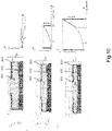
- Figure 8 shows a side section of the device 300, in particular the compenetration of cushioning element 301 in conditioning element 302 is shown.
- Device 300 has a tapered end, that is an upper surface that tends to go downwards, allowing an interpenetration so that the dimension D1 is greater than the dimension D2, both shown in figure 8 , D2 having a height comprised between 0 mm and 10 mm, and the upper surface of the device 300 decrease, that is have a decreasing height towards a front end, with an angle comprised between 15° and 20° with respect to an horizontal axis x-x.
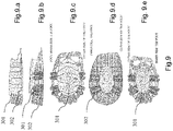
- Figure 9 shows differentiated load bearing capacity regions of the device 300.
- figure 9.a shows, a section of cushioning element 301 coupled to the conditioning element 302, in which a low bearing region corresponds to the central body, with the main function of cushioning at the heel spine area.
- figure 9.a is also shown, with a different filling sign, a back portion having high load bearing capacity, for stabilization and propulsion.
- figures 9.b and 9.c shows, respectively a side view and an upper view, of a medium bearing capacity region, corresponding to independent side protrusions radially arranged to the low-bearing capacity region. The functions of medium-bearing region are to stabilize and bring the foot axis back to a neutral position.
- Back gathered protrusions 301e have a high bearing capacity compared to side protrusions 301d, that have medium bearing capacity, and are higher in order to provide an increased support and stability. Moreover, back gathered protrusions 301e are advantageously characterized by an upper inclined surface to provide an adequate propulsion during the detachment of the foot from the ground during the deambulation.
- Figure 9.c shows the cushioning element 301 of the device 300, highlighting the high bearing capacity region corresponding to the side protrusions and a crown region for connecting the different areas.
- the crown region is important to obtain a controlled deformation being correlated to the type of mechanical response that the device 300 should provide.
- Figure 9.d shows a conditioning element 302 in which are highlighted, in addition to the previous regions, expansion seats for the cushioning element 301 to be deformed under un applied load.
- Figure 10 shows a mechanical behavior of the device 300 in use, i.e. the progress of the device reaction depending on the compression force applied to it.
- Figure 11 shows the device 200, 300 integrated in a sole of a footwear and worn by a user.
- Fig. 11.a shows that the axis of the sole forms a certain angle with the axis of the leg at rest, i.e. before the action of the force of compression due to the deambulation.
- the force of compression F can act centrally with respect to the axis of the sole or sideways, towards inside in case of pronation of the foot, or towards outside in case of supination of the foot.
- Figure 11.b shows that, as a result of the action of the force of compression F, the device 200, 300 deforms only in the stressed region, without involving the adjacent region. In particular, the device 200, 300 returns a force of reaction to the compression such as to bring the user's leg back on axis, this way preventing mechanical traumas on the lower joints.
- Such an advantageous behavior of the device 200, 300 is due to the geometry of the elements 301, 302, 303, to their shape and to the mutual arrangement of full and empty regions. Furthermore, the presence in the device 200, 300 of regions characterized by a differentiated load bearing capacity and the presence of holes and channels that allow the spill of the air, optimize the mechanical response to the compression loads.
- Figure 11.c shows how the device 200, 300, thanks to independent areas of reaction, that is regions with differentiated load bearing capacity, is able to dampen any possible roughness from the bottom of the floor or of the ground, advantageously avoiding the rotation of the sole on which the device is applied and the consequent rotation of a user's leg axis. Such an undesired rotation could in fact lead to dislocations and distortions. Therefore, the variable geometry of the device allows an 'active' and advantageous behavior.
- Figure 12 shows the definition of three different measurements of the device 200, 300 in relation to three shoe size macro-groups.
- the obtained proportion allows to guarantee the correct relationship between the mechanical response of the device and the body weight of a user.
- Figure 13 shows views in section, highlighting geometrical characteristics of the device, in particular side and rear inclinations which allow an easy deambulation, especially when the foot is detached from the ground.
- the angle formed between the lower surface of the cushioning element 301 and the ground, with respect to the central axis passing through the heel of the shoe, is called ⁇
- the angle formed between the back gathered protrusions 301e of the cushioning element 301 and the level of the conditioning element 302 is called ⁇ .
- figure 14 shows an upper view of the device 300 when integrated in the sole of a shoe, where the angles ⁇ , ⁇ and ⁇ , which define a top view profile of the device 200, 300, are highlighted.
- the angle ⁇ is comprised between 5° and 8°
- the angle ⁇ is comprised between 18° and 20°
- the angle ⁇ is comprised between 21° and 22°.
- the device 300 is therefore integrated in a sole portion corresponding to the heel of a user, at a distance D3 from the outer perimeter of the sole, D3 being comprised between 0% and 18% of a width D4 of the sole in its rear portion corresponding to the heel, as shown in Figure 14 .
- the device 300 is integrated in the sole of a footwear, in such a way that the conditioning element 302 is an integral part of the sole, being integrated in a sole portion corresponding to the heel of a user, and the cushioning element 301 is arranged above that portion.
- the conditioning element 302 corresponds to a portion of the tread of the footwear.
- the device suitable for being integrated in footwears soles, acting as cushioning, energy dissipation and stabilization means according to the invention allows to absorb and dissipate the energy generated during the first instant of foot-ground interaction ("heel strike") and to limit the deleterious stresses transmitted to the bony joints.
- a further advantage of the device suitable for being integrated in footwears soles, acting as cushioning, energy dissipation and stabilization means according to the invention is to be able to adequately modulate the force of reaction during the discharge stage, also known as "rebound" force, in such a way that this is compatible with the user's biomechanical requirements.
- Another advantage of the device suitable for being integrated in footwears soles, acting as cushioning, energy dissipation and stabilization means according to the invention is to ensure the stabilization of the heel along the tibia / fibula direction while walking and to avoid one of the main causes of injury on the work, that is the dislocations.
- the device suitable for being integrated in footwears soles, acting as cushioning, energy dissipation and stabilization means according to the invention maximizes comfort and stability thanks to the positioning in correspondence with almost the entire heel of the sole, supporting the entire area of the heel.
- the device suitable for being integrated in footwears soles, acting as cushioning, energy dissipation and stabilization means according to the invention allows to maintain its characteristics for the entire life cycle of the footwear.
Landscapes
- Health & Medical Sciences (AREA)
- Epidemiology (AREA)
- General Health & Medical Sciences (AREA)
- Public Health (AREA)
- Chemical & Material Sciences (AREA)
- Engineering & Computer Science (AREA)
- Materials Engineering (AREA)
- Footwear And Its Accessory, Manufacturing Method And Apparatuses (AREA)
Claims (9)
- Vorrichtung (300), die geeignet ist, um in Schuhsohlen integriert zu werden und die als Mittel für die Dämpfung, Energieableitung und Stabilisierung wirkt und Folgendes umfasst:- ein Dämpfungselement (301), das aus einem ersten Material gefertigt ist, aufweisend ein viskoelastisches Verhalten, umfassend eine vorgegebene Abwechslung von ersten Regionen, die mit dem ersten viskoelastischen Material gefüllt sind, und ersten Regionen, die frei vom ersten viskoelastischen Material sind, wobei es sich um erste Durchführungslöcher (301f) und zweite Durchführungslöcher (301c) und Kanäle (301i) handelt, die das Ausströmen von Luft aus der Vorrichtung (300) ermöglichen, wenn die Vorrichtung (300) einer Druckbelastung ausgesetzt ist;- ein Konditionierungselement (302), wobei das Dämpfungselement auf dem Konditionierungselement positioniert ist und das Konditionierungselement aus einem zweiten Material gefertigt ist, aufweisend ein viskoelastisches Verhalten, das steifer ist als das erste Material, aufweisend ein viskoelastisches Verhalten, umfassend eine vorgegebene Abwechslung zweiter Regionen, die mit dem zweiten viskoelastischen Material gefüllt sind, und zweiter Regionen, die frei vom zweiten viskoelastischen Material sind, wobei die mit dem ersten viskoelastischen Material gefüllten ersten Regionen und die ersten Regionen, die frei vom ersten viskoelastischen Material sind, des Dämpfungselements (301) ausgelegt sind, um mit den entsprechenden zweiten Regionen, die frei vom zweiten viskoelastischen Material sind, und den zweiten Regionen, die mit dem zweiten viskoelastischen Material gefüllt sind, des Konditionierungselements (302) gekuppelt zu werden, wenn die Vorrichtung (300) einer Druckbelastung ausgesetzt ist, und- ein Aufnahmeelement (303), das über dem Dämpfungselement (301) angeordnet ist und auch das Konditionierungselement (302) bedeckt,dadurch gekennzeichnet, dass die ersten gefüllten Regionen des Dämpfungselements (301) seitliche Vorsprünge (301d) und hintere Vorsprünge (301e) sind, wobei sich die seitlichen Vorsprünge (301d) und die hinteren Vorsprünge (301e) von der oberen Oberfläche zur unteren Oberfläche des Dämpfungselements (301) erstrecken.
- Vorrichtung (300) nach Anspruch 1, dadurch gekennzeichnet, dass die seitlichen Vorsprünge (301d) und die hinteren Vorsprünge (301e) C-förmig sind.
- Vorrichtung (300) nach Anspruch 1, dadurch gekennzeichnet, dass die seitlichen Vorsprünge (301d) mindestens vier sind und an jeder Seite in Zweiergruppen angeordnet sind, und die hinteren Vorsprünge (301e) mindestens vier gruppierte Vorsprünge sind.
- Vorrichtung (300) nach Anspruch 1, dadurch gekennzeichnet, dass das Dämpfungselement (301) eine mittige ebene Region (301a) umfasst, die die ersten Durchführungslöcher (301f) und Kanäle (301fa) umfasst, und einen regulierenden Verformungskranz (301b), der sich am Umfang der mittigen ebenen Region (301a) befindet und die zweiten Durchführungslöcher (301) und die seitlichen Vorsprünge (301d) und die hinteren Vorsprünge (301e) umfasst.
- Vorrichtung (300) nach Anspruch 1, dadurch gekennzeichnet, dass die zweiten gefüllten Regionen des Konditionierungselements (302) zwei seitliche Vorsprünge (302b) an jeder Seite und ein hinterer Vorsprung (302c) sind.
- Vorrichtung (300) nach den Ansprüchen 1 und 5, dadurch gekennzeichnet, dass das Konditionierungselement (302) ein flaches Element ist, das eine oberseitige hohle Region (302a) umfasst, aufweisend einen Umfangsabschnitt, der die seitlichen Vorsprünge (302b) und den hinteren Vorsprung (302c) umfasst.
- Vorrichtung (300) nach Anspruch 1, 4 und 6, dadurch gekennzeichnet, dass das Aufnahmeelement (303) ein innen hohles Element ist, das an seiner oberen Oberfläche ein mittiges Loch (303a) umfasst und in Übereinstimmung jeweils mit den mittigen Ebenen Regionen (301a) und der mittigen hohlen Region (302a) des Dämpfungselements (301) und des Konditionierungselements (302) platziert ist.
- Vorrichtung (300) nach Anspruch 1 und 4, dadurch gekennzeichnet, dass das Dämpfungselement (301) und das Konditionierungselement (302) Folgendes umfassen:- eine Region mit geringer Tragfähigkeit, die der mittigen ebenen Region (301a) entspricht und ausgelegt ist, um eine leichte Last zu tragen und als Dämpfungsmittel zu wirken;- eine rückseitige Region, die die hinteren Vorsprünge (301e) umfasst, eine hohe Tragfähigkeit aufweist und ausgelegt ist, um eine hohe Last zu tragen und die als Stabilisierungs- und Antriebsmittel wirkt;- eine Region mit mittlerer Tragfähigkeit, die den seitlichen Vorsprüngen (301d) entspricht, radial angeordnet zur Region mit geringer Tragfähigkeit, wirkend als Stabilisierungs- und Ausrichtungsmittel, um die Fußachse wieder in eine neutrale Stellung zu bringen.
- Sohle, umfassend eine Vorrichtung (300) gemäß Anspruch 1 bis 8, die geeignet ist, um in Schuhe integriert zu werden und die als Mittel für die Dämpfung, Energieableitung und Stabilisierung wirkt.
Applications Claiming Priority (2)
| Application Number | Priority Date | Filing Date | Title |
|---|---|---|---|
| IT102017000089835A IT201700089835A1 (it) | 2017-08-03 | 2017-08-03 | Sistema attivo a geometria variabile con funzioni di ammortizzazione, dissipazione di energia e stabilizzazione, integrabile nelle suole delle calzature |
| PCT/IB2018/055824 WO2019026025A1 (en) | 2017-08-03 | 2018-08-02 | DEVICE CAPABLE OF BEING INTEGRATED IN FOOTWEAR FOOTWEAR AS DAMPING, DISSIPATING AND STABILIZING MEANS |
Publications (2)
| Publication Number | Publication Date |
|---|---|
| EP3661383A1 EP3661383A1 (de) | 2020-06-10 |
| EP3661383B1 true EP3661383B1 (de) | 2022-05-11 |
Family
ID=60991059
Family Applications (1)
| Application Number | Title | Priority Date | Filing Date |
|---|---|---|---|
| EP18759409.8A Active EP3661383B1 (de) | 2017-08-03 | 2018-08-02 | Zur integration in schuhsohlen geeignete vorrichtung, die als polsterungs-, energieableitungs- und stabilisierungsmittel wirkt |
Country Status (12)
| Country | Link |
|---|---|
| US (1) | US11330862B2 (de) |
| EP (1) | EP3661383B1 (de) |
| AU (1) | AU2018309426B2 (de) |
| CA (1) | CA3071781A1 (de) |
| DK (1) | DK3661383T3 (de) |
| ES (1) | ES2923910T3 (de) |
| HU (1) | HUE059220T2 (de) |
| IT (1) | IT201700089835A1 (de) |
| PL (1) | PL3661383T3 (de) |
| PT (1) | PT3661383T (de) |
| RU (1) | RU2766289C1 (de) |
| WO (1) | WO2019026025A1 (de) |
Families Citing this family (2)
| Publication number | Priority date | Publication date | Assignee | Title |
|---|---|---|---|---|
| IT201700089835A1 (it) * | 2017-08-03 | 2019-02-03 | Base Prot S R L | Sistema attivo a geometria variabile con funzioni di ammortizzazione, dissipazione di energia e stabilizzazione, integrabile nelle suole delle calzature |
| IT202200024858A1 (it) * | 2022-12-01 | 2024-06-01 | Pezzol Ind S R L | Componente di base o battistrada per una calzatura come pure calzatura includente lo stesso componente. |
Family Cites Families (35)
| Publication number | Priority date | Publication date | Assignee | Title |
|---|---|---|---|---|
| US4342157A (en) | 1980-08-11 | 1982-08-03 | Sam Gilbert | Shock absorbing partially liquid-filled cushion for shoes |
| US4715130A (en) * | 1985-09-20 | 1987-12-29 | Alessandro Scatena | Cushion system for shoes |
| JPS6343925Y2 (de) | 1986-04-11 | 1988-11-16 | ||
| US4815221A (en) | 1987-02-06 | 1989-03-28 | Reebok International Ltd. | Shoe with energy control system |
| BR8806281A (pt) * | 1988-11-25 | 1990-07-24 | Sao Paulo Alpargatas | Sistema de amortecimento de impactos aplicavel em sapatos esportivos |
| US4934072A (en) | 1989-04-14 | 1990-06-19 | Wolverine World Wide, Inc. | Fluid dynamic shoe |
| IT1226514B (it) * | 1989-05-24 | 1991-01-24 | Fila Sport | Calzatura sportiva incorporante, nel tallone, un inserto elastico. |
| US5155927A (en) | 1991-02-20 | 1992-10-20 | Asics Corporation | Shoe comprising liquid cushioning element |
| US6266897B1 (en) | 1994-10-21 | 2001-07-31 | Adidas International B.V. | Ground-contacting systems having 3D deformation elements for use in footwear |
| US5718063A (en) * | 1995-07-17 | 1998-02-17 | Asics Corporation | Midsole cushioning system |
| US5704137A (en) | 1995-12-22 | 1998-01-06 | Brooks Sports, Inc. | Shoe having hydrodynamic pad |
| WO2000010417A1 (en) * | 1997-07-30 | 2000-03-02 | Britek Footwear Development, Llc | Sole construction for energy storage and rebound |
| US20020121031A1 (en) * | 1998-01-30 | 2002-09-05 | Steven Smith | 2a improvements |
| DE19836657A1 (de) | 1998-08-13 | 2000-02-17 | Hoechst Trespaphan Gmbh | Mehrschichtig biaxial orientierte Polypropylenfolie mit verbesserter Barriere, Verfahren zu ihrer Herstellung und ihre Verwendung |
| DE19839657A1 (de) * | 1998-09-01 | 2000-03-02 | Ming Huo | Flaches Dämpfungselement |
| DE10212862C1 (de) * | 2002-03-22 | 2003-10-30 | Adidas Int Marketing Bv | Schuhsohle und Schuh |
| ITTO20020962A1 (it) * | 2002-11-08 | 2004-05-09 | Dieffegi S P A | Suola di scarpa con inserto. |
| US7000335B2 (en) | 2003-07-16 | 2006-02-21 | Nike, Inc. | Footwear with a sole structure incorporating a lobed fluid-filled chamber |
| US7020988B1 (en) | 2003-08-29 | 2006-04-04 | Pierre Andre Senizergues | Footwear with enhanced impact protection |
| US7082704B2 (en) * | 2004-07-30 | 2006-08-01 | James L. Throneburg | Insole, and footwear system incorporating same |
| DE102005037781A1 (de) | 2005-08-10 | 2007-02-22 | Louis Steitz Secura Gmbh + Co Kg | Schuhe für auftrittsempfindliche Füsse |
| WO2008058147A2 (en) * | 2006-11-06 | 2008-05-15 | Newton Running Company, Inc. | Sole construction for energy storage and rebound |
| US7757411B2 (en) * | 2007-04-25 | 2010-07-20 | Wolverine World Wide, Inc. | Shock absorbing footwear construction |
| US8209885B2 (en) * | 2009-05-11 | 2012-07-03 | Brooks Sports, Inc. | Shoe assembly with non-linear viscous liquid |
| US8557157B2 (en) * | 2009-07-01 | 2013-10-15 | Wolverine World Wide, Inc. | Method of manufacturing an article of footwear having a direct attach sole component |
| NL2003367C2 (en) * | 2009-08-20 | 2011-02-22 | Sara Lee De Nv | Cushioning element, footwear, insole, deformable filling, and envelope. |
| DE102012021696A1 (de) * | 2012-10-30 | 2014-04-30 | Bauerfeind Ag | Viscoelastisches Element |
| DK2732716T3 (en) | 2012-11-14 | 2015-03-30 | Arbesko Gruppen Ab | Shock absorber |
| US9603414B2 (en) * | 2013-03-15 | 2017-03-28 | Nike, Inc. | Fluid-filled chamber with a tensile element |
| US10383391B2 (en) * | 2014-03-06 | 2019-08-20 | Asics Corporation | Shock absorbing structure and shoe to which the shock absorbing structure is applied |
| PL3195747T3 (pl) * | 2014-04-09 | 2019-06-28 | Arbesko-Gruppen Ab | Amortyzator do stosowania w bucie |
| WO2017035196A1 (en) * | 2015-08-25 | 2017-03-02 | Nike, Inc. | Footwear sole structure with carrier and frame |
| TWI752453B (zh) * | 2015-09-24 | 2022-01-11 | 荷蘭商耐克創新有限合夥公司 | 具有帶部分限制的顆粒泡棉之鞋類物品 |
| IT201700089835A1 (it) * | 2017-08-03 | 2019-02-03 | Base Prot S R L | Sistema attivo a geometria variabile con funzioni di ammortizzazione, dissipazione di energia e stabilizzazione, integrabile nelle suole delle calzature |
| CN115568658B (zh) * | 2019-01-31 | 2026-03-24 | 耐克创新有限合伙公司 | 具有流体填充囊元件的鞋底结构和鞋类物品 |
-
2017
- 2017-08-03 IT IT102017000089835A patent/IT201700089835A1/it unknown
-
2018
- 2018-08-02 DK DK18759409.8T patent/DK3661383T3/da active
- 2018-08-02 CA CA3071781A patent/CA3071781A1/en active Pending
- 2018-08-02 PT PT187594098T patent/PT3661383T/pt unknown
- 2018-08-02 PL PL18759409.8T patent/PL3661383T3/pl unknown
- 2018-08-02 EP EP18759409.8A patent/EP3661383B1/de active Active
- 2018-08-02 US US16/634,794 patent/US11330862B2/en active Active
- 2018-08-02 ES ES18759409T patent/ES2923910T3/es active Active
- 2018-08-02 WO PCT/IB2018/055824 patent/WO2019026025A1/en not_active Ceased
- 2018-08-02 RU RU2020107162A patent/RU2766289C1/ru active
- 2018-08-02 AU AU2018309426A patent/AU2018309426B2/en active Active
- 2018-08-02 HU HUE18759409A patent/HUE059220T2/hu unknown
Also Published As
| Publication number | Publication date |
|---|---|
| AU2018309426B2 (en) | 2024-02-29 |
| DK3661383T3 (da) | 2022-08-01 |
| IT201700089835A1 (it) | 2019-02-03 |
| AU2018309426A1 (en) | 2020-03-05 |
| RU2766289C1 (ru) | 2022-03-11 |
| CA3071781A1 (en) | 2019-02-07 |
| PT3661383T (pt) | 2022-08-22 |
| WO2019026025A1 (en) | 2019-02-07 |
| HUE059220T2 (hu) | 2022-10-28 |
| EP3661383A1 (de) | 2020-06-10 |
| US11330862B2 (en) | 2022-05-17 |
| US20200205513A1 (en) | 2020-07-02 |
| PL3661383T3 (pl) | 2022-09-12 |
| ES2923910T3 (es) | 2022-10-03 |
Similar Documents
| Publication | Publication Date | Title |
|---|---|---|
| EP0780064B1 (de) | Hydrodynamisches Schuhpolster und damit versehener Schuh | |
| US6665958B2 (en) | Protective cage for footwear bladder | |
| EP3595478B1 (de) | Polsterungselement für schuhartikel | |
| EP0714613B1 (de) | Schuhwerk mit mehrerer Flüssigkeit enthaltenden Gliedern | |
| US5784807A (en) | Fluid filled support system for footwear | |
| KR0140071B1 (ko) | 반응 에너지 유체 충전 토로이드 장치를 갖춘 신발 창 | |
| US6694642B2 (en) | Shoe incorporating improved shock absorption and stabilizing elements | |
| EP2929791B1 (de) | Schuhartikel mit erhöhter Plattensohlenstruktur | |
| US5313717A (en) | Reactive energy fluid filled apparatus providing cushioning, support, stability and a custom fit in a shoe | |
| US6598320B2 (en) | Shoe incorporating improved shock absorption and stabilizing elements | |
| US4535553A (en) | Shock absorbing sole layer | |
| US9451805B2 (en) | Article of footwear with support assembly having primary and secondary members | |
| US20150033579A1 (en) | Article of footwear with support assembly having tubular members | |
| KR20200009056A (ko) | 등급화된 응답을 갖는 중창 | |
| US20140101972A1 (en) | Shock absorbing shoes with triangle shock absorbing space | |
| US20070294832A1 (en) | Air cushion with multistage shock-absorbing assembly and fabricating method | |
| KR19980025330A (ko) | 신발용 충격흡수시스템 | |
| US20110162233A1 (en) | Air cushion with multistage shock-absorbing assembly and fabricating method | |
| EP3661383B1 (de) | Zur integration in schuhsohlen geeignete vorrichtung, die als polsterungs-, energieableitungs- und stabilisierungsmittel wirkt | |
| WO2009075407A1 (en) | The elastic sole and its shoes having elastic reaction force and shock absorption | |
| US20170013912A1 (en) | Footwear Comprising an Elastic Intermediate Sole | |
| KR101251572B1 (ko) | 트라이앵글 충격흡수부를 구비한 충격흡수 신발 | |
| KR101298196B1 (ko) | 보행 안정성을 강화시킨 기능성 신발창. | |
| KR19990069793A (ko) | 신발의 쿠션완충장치 | |
| KR102001997B1 (ko) | 기능성 신발 밑창을 구비하는 신발 |
Legal Events
| Date | Code | Title | Description |
|---|---|---|---|
| STAA | Information on the status of an ep patent application or granted ep patent |
Free format text: STATUS: UNKNOWN |
|
| STAA | Information on the status of an ep patent application or granted ep patent |
Free format text: STATUS: THE INTERNATIONAL PUBLICATION HAS BEEN MADE |
|
| PUAI | Public reference made under article 153(3) epc to a published international application that has entered the european phase |
Free format text: ORIGINAL CODE: 0009012 |
|
| STAA | Information on the status of an ep patent application or granted ep patent |
Free format text: STATUS: REQUEST FOR EXAMINATION WAS MADE |
|
| 17P | Request for examination filed |
Effective date: 20200217 |
|
| AK | Designated contracting states |
Kind code of ref document: A1 Designated state(s): AL AT BE BG CH CY CZ DE DK EE ES FI FR GB GR HR HU IE IS IT LI LT LU LV MC MK MT NL NO PL PT RO RS SE SI SK SM TR |
|
| AX | Request for extension of the european patent |
Extension state: BA ME |
|
| DAV | Request for validation of the european patent (deleted) | ||
| DAX | Request for extension of the european patent (deleted) | ||
| RIN1 | Information on inventor provided before grant (corrected) |
Inventor name: DE LUCA, CATALDO |
|
| GRAP | Despatch of communication of intention to grant a patent |
Free format text: ORIGINAL CODE: EPIDOSNIGR1 |
|
| STAA | Information on the status of an ep patent application or granted ep patent |
Free format text: STATUS: GRANT OF PATENT IS INTENDED |
|
| INTG | Intention to grant announced |
Effective date: 20220222 |
|
| GRAS | Grant fee paid |
Free format text: ORIGINAL CODE: EPIDOSNIGR3 |
|
| GRAA | (expected) grant |
Free format text: ORIGINAL CODE: 0009210 |
|
| STAA | Information on the status of an ep patent application or granted ep patent |
Free format text: STATUS: THE PATENT HAS BEEN GRANTED |
|
| AK | Designated contracting states |
Kind code of ref document: B1 Designated state(s): AL AT BE BG CH CY CZ DE DK EE ES FI FR GB GR HR HU IE IS IT LI LT LU LV MC MK MT NL NO PL PT RO RS SE SI SK SM TR |
|
| REG | Reference to a national code |
Ref country code: GB Ref legal event code: FG4D |
|
| REG | Reference to a national code |
Ref country code: CH Ref legal event code: EP |
|
| REG | Reference to a national code |
Ref country code: AT Ref legal event code: REF Ref document number: 1490653 Country of ref document: AT Kind code of ref document: T Effective date: 20220515 |
|
| REG | Reference to a national code |
Ref country code: DE Ref legal event code: R096 Ref document number: 602018035466 Country of ref document: DE |
|
| REG | Reference to a national code |
Ref country code: IE Ref legal event code: FG4D |
|
| REG | Reference to a national code |
Ref country code: RO Ref legal event code: EPE |
|
| REG | Reference to a national code |
Ref country code: NL Ref legal event code: FP |
|
| REG | Reference to a national code |
Ref country code: DK Ref legal event code: T3 Effective date: 20220727 |
|
| REG | Reference to a national code |
Ref country code: SE Ref legal event code: TRGR |
|
| REG | Reference to a national code |
Ref country code: PT Ref legal event code: SC4A Ref document number: 3661383 Country of ref document: PT Date of ref document: 20220822 Kind code of ref document: T Free format text: AVAILABILITY OF NATIONAL TRANSLATION Effective date: 20220811 |
|
| REG | Reference to a national code |
Ref country code: LT Ref legal event code: MG9D |
|
| REG | Reference to a national code |
Ref country code: NO Ref legal event code: T2 Effective date: 20220511 |
|
| REG | Reference to a national code |
Ref country code: ES Ref legal event code: FG2A Ref document number: 2923910 Country of ref document: ES Kind code of ref document: T3 Effective date: 20221003 |
|
| REG | Reference to a national code |
Ref country code: HU Ref legal event code: AG4A Ref document number: E059220 Country of ref document: HU |
|
| PG25 | Lapsed in a contracting state [announced via postgrant information from national office to epo] |
Ref country code: LT Free format text: LAPSE BECAUSE OF FAILURE TO SUBMIT A TRANSLATION OF THE DESCRIPTION OR TO PAY THE FEE WITHIN THE PRESCRIBED TIME-LIMIT Effective date: 20220511 Ref country code: HR Free format text: LAPSE BECAUSE OF FAILURE TO SUBMIT A TRANSLATION OF THE DESCRIPTION OR TO PAY THE FEE WITHIN THE PRESCRIBED TIME-LIMIT Effective date: 20220511 Ref country code: GR Free format text: LAPSE BECAUSE OF FAILURE TO SUBMIT A TRANSLATION OF THE DESCRIPTION OR TO PAY THE FEE WITHIN THE PRESCRIBED TIME-LIMIT Effective date: 20220812 Ref country code: FI Free format text: LAPSE BECAUSE OF FAILURE TO SUBMIT A TRANSLATION OF THE DESCRIPTION OR TO PAY THE FEE WITHIN THE PRESCRIBED TIME-LIMIT Effective date: 20220511 |
|
| PG25 | Lapsed in a contracting state [announced via postgrant information from national office to epo] |
Ref country code: RS Free format text: LAPSE BECAUSE OF FAILURE TO SUBMIT A TRANSLATION OF THE DESCRIPTION OR TO PAY THE FEE WITHIN THE PRESCRIBED TIME-LIMIT Effective date: 20220511 Ref country code: LV Free format text: LAPSE BECAUSE OF FAILURE TO SUBMIT A TRANSLATION OF THE DESCRIPTION OR TO PAY THE FEE WITHIN THE PRESCRIBED TIME-LIMIT Effective date: 20220511 Ref country code: IS Free format text: LAPSE BECAUSE OF FAILURE TO SUBMIT A TRANSLATION OF THE DESCRIPTION OR TO PAY THE FEE WITHIN THE PRESCRIBED TIME-LIMIT Effective date: 20220911 |
|
| PG25 | Lapsed in a contracting state [announced via postgrant information from national office to epo] |
Ref country code: SM Free format text: LAPSE BECAUSE OF FAILURE TO SUBMIT A TRANSLATION OF THE DESCRIPTION OR TO PAY THE FEE WITHIN THE PRESCRIBED TIME-LIMIT Effective date: 20220511 Ref country code: SK Free format text: LAPSE BECAUSE OF FAILURE TO SUBMIT A TRANSLATION OF THE DESCRIPTION OR TO PAY THE FEE WITHIN THE PRESCRIBED TIME-LIMIT Effective date: 20220511 Ref country code: EE Free format text: LAPSE BECAUSE OF FAILURE TO SUBMIT A TRANSLATION OF THE DESCRIPTION OR TO PAY THE FEE WITHIN THE PRESCRIBED TIME-LIMIT Effective date: 20220511 |
|
| REG | Reference to a national code |
Ref country code: DE Ref legal event code: R097 Ref document number: 602018035466 Country of ref document: DE |
|
| PLBE | No opposition filed within time limit |
Free format text: ORIGINAL CODE: 0009261 |
|
| STAA | Information on the status of an ep patent application or granted ep patent |
Free format text: STATUS: NO OPPOSITION FILED WITHIN TIME LIMIT |
|
| PG25 | Lapsed in a contracting state [announced via postgrant information from national office to epo] |
Ref country code: MC Free format text: LAPSE BECAUSE OF FAILURE TO SUBMIT A TRANSLATION OF THE DESCRIPTION OR TO PAY THE FEE WITHIN THE PRESCRIBED TIME-LIMIT Effective date: 20220511 Ref country code: AL Free format text: LAPSE BECAUSE OF FAILURE TO SUBMIT A TRANSLATION OF THE DESCRIPTION OR TO PAY THE FEE WITHIN THE PRESCRIBED TIME-LIMIT Effective date: 20220511 |
|
| 26N | No opposition filed |
Effective date: 20230214 |
|
| PG25 | Lapsed in a contracting state [announced via postgrant information from national office to epo] |
Ref country code: LU Free format text: LAPSE BECAUSE OF NON-PAYMENT OF DUE FEES Effective date: 20220802 |
|
| PG25 | Lapsed in a contracting state [announced via postgrant information from national office to epo] |
Ref country code: SI Free format text: LAPSE BECAUSE OF FAILURE TO SUBMIT A TRANSLATION OF THE DESCRIPTION OR TO PAY THE FEE WITHIN THE PRESCRIBED TIME-LIMIT Effective date: 20220511 |
|
| REG | Reference to a national code |
Ref country code: AT Ref legal event code: UEP Ref document number: 1490653 Country of ref document: AT Kind code of ref document: T Effective date: 20220511 |
|
| PG25 | Lapsed in a contracting state [announced via postgrant information from national office to epo] |
Ref country code: MK Free format text: LAPSE BECAUSE OF FAILURE TO SUBMIT A TRANSLATION OF THE DESCRIPTION OR TO PAY THE FEE WITHIN THE PRESCRIBED TIME-LIMIT Effective date: 20220511 Ref country code: CY Free format text: LAPSE BECAUSE OF FAILURE TO SUBMIT A TRANSLATION OF THE DESCRIPTION OR TO PAY THE FEE WITHIN THE PRESCRIBED TIME-LIMIT Effective date: 20220511 |
|
| PG25 | Lapsed in a contracting state [announced via postgrant information from national office to epo] |
Ref country code: MT Free format text: LAPSE BECAUSE OF FAILURE TO SUBMIT A TRANSLATION OF THE DESCRIPTION OR TO PAY THE FEE WITHIN THE PRESCRIBED TIME-LIMIT Effective date: 20220511 |
|
| PGFP | Annual fee paid to national office [announced via postgrant information from national office to epo] |
Ref country code: NL Payment date: 20250821 Year of fee payment: 8 |
|
| PGFP | Annual fee paid to national office [announced via postgrant information from national office to epo] |
Ref country code: HU Payment date: 20250825 Year of fee payment: 8 |
|
| PGFP | Annual fee paid to national office [announced via postgrant information from national office to epo] |
Ref country code: PT Payment date: 20250729 Year of fee payment: 8 Ref country code: ES Payment date: 20250926 Year of fee payment: 8 |
|
| PGFP | Annual fee paid to national office [announced via postgrant information from national office to epo] |
Ref country code: DE Payment date: 20250820 Year of fee payment: 8 Ref country code: DK Payment date: 20250825 Year of fee payment: 8 |
|
| PGFP | Annual fee paid to national office [announced via postgrant information from national office to epo] |
Ref country code: NO Payment date: 20250826 Year of fee payment: 8 |
|
| PGFP | Annual fee paid to national office [announced via postgrant information from national office to epo] |
Ref country code: PL Payment date: 20250730 Year of fee payment: 8 Ref country code: TR Payment date: 20250729 Year of fee payment: 8 Ref country code: IT Payment date: 20250708 Year of fee payment: 8 |
|
| PGFP | Annual fee paid to national office [announced via postgrant information from national office to epo] |
Ref country code: BG Payment date: 20250822 Year of fee payment: 8 Ref country code: BE Payment date: 20250820 Year of fee payment: 8 Ref country code: GB Payment date: 20250820 Year of fee payment: 8 |
|
| PGFP | Annual fee paid to national office [announced via postgrant information from national office to epo] |
Ref country code: FR Payment date: 20250828 Year of fee payment: 8 Ref country code: AT Payment date: 20250821 Year of fee payment: 8 |
|
| PGFP | Annual fee paid to national office [announced via postgrant information from national office to epo] |
Ref country code: CH Payment date: 20250901 Year of fee payment: 8 Ref country code: SE Payment date: 20250820 Year of fee payment: 8 |
|
| PGFP | Annual fee paid to national office [announced via postgrant information from national office to epo] |
Ref country code: IE Payment date: 20250820 Year of fee payment: 8 Ref country code: CZ Payment date: 20250729 Year of fee payment: 8 |
|
| PGFP | Annual fee paid to national office [announced via postgrant information from national office to epo] |
Ref country code: RO Payment date: 20250731 Year of fee payment: 8 |