EP3661009A1 - Erkennung von shoot-through in stromrichtern - Google Patents
Erkennung von shoot-through in stromrichtern Download PDFInfo
- Publication number
- EP3661009A1 EP3661009A1 EP19208691.6A EP19208691A EP3661009A1 EP 3661009 A1 EP3661009 A1 EP 3661009A1 EP 19208691 A EP19208691 A EP 19208691A EP 3661009 A1 EP3661009 A1 EP 3661009A1
- Authority
- EP
- European Patent Office
- Prior art keywords
- shoot
- capacitor
- voltage value
- voltage
- condition
- Prior art date
- Legal status (The legal status is an assumption and is not a legal conclusion. Google has not performed a legal analysis and makes no representation as to the accuracy of the status listed.)
- Granted
Links
Images


Classifications
-
- H—ELECTRICITY
- H02—GENERATION; CONVERSION OR DISTRIBUTION OF ELECTRIC POWER
- H02M—APPARATUS FOR CONVERSION BETWEEN AC AND AC, BETWEEN AC AND DC, OR BETWEEN DC AND DC, AND FOR USE WITH MAINS OR SIMILAR POWER SUPPLY SYSTEMS; CONVERSION OF DC OR AC INPUT POWER INTO SURGE OUTPUT POWER; CONTROL OR REGULATION THEREOF
- H02M1/00—Details of apparatus for conversion
- H02M1/08—Circuits specially adapted for the generation of control voltages for semiconductor devices incorporated in static converters
-
- H—ELECTRICITY
- H02—GENERATION; CONVERSION OR DISTRIBUTION OF ELECTRIC POWER
- H02H—EMERGENCY PROTECTIVE CIRCUIT ARRANGEMENTS
- H02H7/00—Emergency protective circuit arrangements specially adapted for specific types of electric machines or apparatus or for sectionalised protection of cable or line systems, and effecting automatic switching in the event of an undesired change from normal working conditions
- H02H7/10—Emergency protective circuit arrangements specially adapted for specific types of electric machines or apparatus or for sectionalised protection of cable or line systems, and effecting automatic switching in the event of an undesired change from normal working conditions for converters; for rectifiers
- H02H7/12—Emergency protective circuit arrangements specially adapted for specific types of electric machines or apparatus or for sectionalised protection of cable or line systems, and effecting automatic switching in the event of an undesired change from normal working conditions for converters; for rectifiers for static converters or rectifiers
- H02H7/122—Emergency protective circuit arrangements specially adapted for specific types of electric machines or apparatus or for sectionalised protection of cable or line systems, and effecting automatic switching in the event of an undesired change from normal working conditions for converters; for rectifiers for static converters or rectifiers for inverters, i.e. DC/AC converters
- H02H7/1225—Emergency protective circuit arrangements specially adapted for specific types of electric machines or apparatus or for sectionalised protection of cable or line systems, and effecting automatic switching in the event of an undesired change from normal working conditions for converters; for rectifiers for static converters or rectifiers for inverters, i.e. DC/AC converters responsive to internal faults, e.g. shoot-through
-
- G—PHYSICS
- G01—MEASURING; TESTING
- G01R—MEASURING ELECTRIC VARIABLES; MEASURING MAGNETIC VARIABLES
- G01R31/00—Arrangements for testing electric properties; Arrangements for locating electric faults; Arrangements for electrical testing characterised by what is being tested not provided for elsewhere
- G01R31/12—Testing dielectric strength or breakdown voltage ; Testing or monitoring effectiveness or level of insulation, e.g. of a cable or of an apparatus, for example using partial discharge measurements; Electrostatic testing
- G01R31/1227—Testing dielectric strength or breakdown voltage ; Testing or monitoring effectiveness or level of insulation, e.g. of a cable or of an apparatus, for example using partial discharge measurements; Electrostatic testing of components, parts or materials
- G01R31/1263—Testing dielectric strength or breakdown voltage ; Testing or monitoring effectiveness or level of insulation, e.g. of a cable or of an apparatus, for example using partial discharge measurements; Electrostatic testing of components, parts or materials of solid or fluid materials, e.g. insulation films, bulk material; of semiconductors or LV electronic components or parts; of cable, line or wire insulation
- G01R31/129—Testing dielectric strength or breakdown voltage ; Testing or monitoring effectiveness or level of insulation, e.g. of a cable or of an apparatus, for example using partial discharge measurements; Electrostatic testing of components, parts or materials of solid or fluid materials, e.g. insulation films, bulk material; of semiconductors or LV electronic components or parts; of cable, line or wire insulation of components or parts made of semiconducting materials; of LV components or parts
-
- G—PHYSICS
- G01—MEASURING; TESTING
- G01R—MEASURING ELECTRIC VARIABLES; MEASURING MAGNETIC VARIABLES
- G01R19/00—Arrangements for measuring currents or voltages or for indicating presence or sign thereof
- G01R19/04—Measuring peak values or amplitude or envelope of AC or of pulses
-
- G—PHYSICS
- G01—MEASURING; TESTING
- G01R—MEASURING ELECTRIC VARIABLES; MEASURING MAGNETIC VARIABLES
- G01R19/00—Arrangements for measuring currents or voltages or for indicating presence or sign thereof
- G01R19/10—Measuring sum, difference or ratio
-
- G—PHYSICS
- G01—MEASURING; TESTING
- G01R—MEASURING ELECTRIC VARIABLES; MEASURING MAGNETIC VARIABLES
- G01R31/00—Arrangements for testing electric properties; Arrangements for locating electric faults; Arrangements for electrical testing characterised by what is being tested not provided for elsewhere
- G01R31/40—Testing power supplies
- G01R31/42—AC power supplies
-
- H—ELECTRICITY
- H02—GENERATION; CONVERSION OR DISTRIBUTION OF ELECTRIC POWER
- H02H—EMERGENCY PROTECTIVE CIRCUIT ARRANGEMENTS
- H02H7/00—Emergency protective circuit arrangements specially adapted for specific types of electric machines or apparatus or for sectionalised protection of cable or line systems, and effecting automatic switching in the event of an undesired change from normal working conditions
- H02H7/10—Emergency protective circuit arrangements specially adapted for specific types of electric machines or apparatus or for sectionalised protection of cable or line systems, and effecting automatic switching in the event of an undesired change from normal working conditions for converters; for rectifiers
- H02H7/12—Emergency protective circuit arrangements specially adapted for specific types of electric machines or apparatus or for sectionalised protection of cable or line systems, and effecting automatic switching in the event of an undesired change from normal working conditions for converters; for rectifiers for static converters or rectifiers
- H02H7/1216—Emergency protective circuit arrangements specially adapted for specific types of electric machines or apparatus or for sectionalised protection of cable or line systems, and effecting automatic switching in the event of an undesired change from normal working conditions for converters; for rectifiers for static converters or rectifiers for AC-AC converters
-
- H—ELECTRICITY
- H02—GENERATION; CONVERSION OR DISTRIBUTION OF ELECTRIC POWER
- H02J—CIRCUIT ARRANGEMENTS OR SYSTEMS FOR SUPPLYING OR DISTRIBUTING ELECTRIC POWER; SYSTEMS FOR STORING ELECTRIC ENERGY
- H02J9/00—Circuit arrangements for emergency or stand-by power supply, e.g. for emergency lighting
- H02J9/04—Circuit arrangements for emergency or stand-by power supply, e.g. for emergency lighting in which the distribution system is disconnected from the normal source and connected to a standby source
- H02J9/06—Circuit arrangements for emergency or stand-by power supply, e.g. for emergency lighting in which the distribution system is disconnected from the normal source and connected to a standby source with automatic change-over, e.g. UPS systems
- H02J9/062—Circuit arrangements for emergency or stand-by power supply, e.g. for emergency lighting in which the distribution system is disconnected from the normal source and connected to a standby source with automatic change-over, e.g. UPS systems for AC powered loads
-
- H—ELECTRICITY
- H02—GENERATION; CONVERSION OR DISTRIBUTION OF ELECTRIC POWER
- H02M—APPARATUS FOR CONVERSION BETWEEN AC AND AC, BETWEEN AC AND DC, OR BETWEEN DC AND DC, AND FOR USE WITH MAINS OR SIMILAR POWER SUPPLY SYSTEMS; CONVERSION OF DC OR AC INPUT POWER INTO SURGE OUTPUT POWER; CONTROL OR REGULATION THEREOF
- H02M1/00—Details of apparatus for conversion
- H02M1/32—Means for protecting converters other than automatic disconnection
- H02M1/325—Means for protecting converters other than automatic disconnection with means for allowing continuous operation despite a fault, i.e. fault tolerant converters
-
- H—ELECTRICITY
- H02—GENERATION; CONVERSION OR DISTRIBUTION OF ELECTRIC POWER
- H02M—APPARATUS FOR CONVERSION BETWEEN AC AND AC, BETWEEN AC AND DC, OR BETWEEN DC AND DC, AND FOR USE WITH MAINS OR SIMILAR POWER SUPPLY SYSTEMS; CONVERSION OF DC OR AC INPUT POWER INTO SURGE OUTPUT POWER; CONTROL OR REGULATION THEREOF
- H02M1/00—Details of apparatus for conversion
- H02M1/38—Means for preventing simultaneous conduction of switches
-
- H—ELECTRICITY
- H02—GENERATION; CONVERSION OR DISTRIBUTION OF ELECTRIC POWER
- H02M—APPARATUS FOR CONVERSION BETWEEN AC AND AC, BETWEEN AC AND DC, OR BETWEEN DC AND DC, AND FOR USE WITH MAINS OR SIMILAR POWER SUPPLY SYSTEMS; CONVERSION OF DC OR AC INPUT POWER INTO SURGE OUTPUT POWER; CONTROL OR REGULATION THEREOF
- H02M5/00—Conversion of AC power input into AC power output, e.g. for change of voltage, for change of frequency, for change of number of phases
- H02M5/40—Conversion of AC power input into AC power output, e.g. for change of voltage, for change of frequency, for change of number of phases with intermediate conversion into DC
- H02M5/42—Conversion of AC power input into AC power output, e.g. for change of voltage, for change of frequency, for change of number of phases with intermediate conversion into DC by static converters
- H02M5/44—Conversion of AC power input into AC power output, e.g. for change of voltage, for change of frequency, for change of number of phases with intermediate conversion into DC by static converters using discharge tubes or semiconductor devices to convert the intermediate DC into AC
- H02M5/453—Conversion of AC power input into AC power output, e.g. for change of voltage, for change of frequency, for change of number of phases with intermediate conversion into DC by static converters using discharge tubes or semiconductor devices to convert the intermediate DC into AC using devices of a triode or transistor type requiring continuous application of a control signal
- H02M5/458—Conversion of AC power input into AC power output, e.g. for change of voltage, for change of frequency, for change of number of phases with intermediate conversion into DC by static converters using discharge tubes or semiconductor devices to convert the intermediate DC into AC using devices of a triode or transistor type requiring continuous application of a control signal using semiconductor devices only
- H02M5/4585—Conversion of AC power input into AC power output, e.g. for change of voltage, for change of frequency, for change of number of phases with intermediate conversion into DC by static converters using discharge tubes or semiconductor devices to convert the intermediate DC into AC using devices of a triode or transistor type requiring continuous application of a control signal using semiconductor devices only having a rectifier with controlled elements
-
- H—ELECTRICITY
- H02—GENERATION; CONVERSION OR DISTRIBUTION OF ELECTRIC POWER
- H02M—APPARATUS FOR CONVERSION BETWEEN AC AND AC, BETWEEN AC AND DC, OR BETWEEN DC AND DC, AND FOR USE WITH MAINS OR SIMILAR POWER SUPPLY SYSTEMS; CONVERSION OF DC OR AC INPUT POWER INTO SURGE OUTPUT POWER; CONTROL OR REGULATION THEREOF
- H02M7/00—Conversion of AC power input into DC power output; Conversion of DC power input into AC power output
- H02M7/42—Conversion of DC power input into AC power output without possibility of reversal
- H02M7/44—Conversion of DC power input into AC power output without possibility of reversal by static converters
- H02M7/48—Conversion of DC power input into AC power output without possibility of reversal by static converters using discharge tubes with control electrode or semiconductor devices with control electrode
- H02M7/53—Conversion of DC power input into AC power output without possibility of reversal by static converters using discharge tubes with control electrode or semiconductor devices with control electrode using devices of a triode or transistor type requiring continuous application of a control signal
- H02M7/537—Conversion of DC power input into AC power output without possibility of reversal by static converters using discharge tubes with control electrode or semiconductor devices with control electrode using devices of a triode or transistor type requiring continuous application of a control signal using semiconductor devices only, e.g. single switched pulse inverters
-
- H—ELECTRICITY
- H02—GENERATION; CONVERSION OR DISTRIBUTION OF ELECTRIC POWER
- H02M—APPARATUS FOR CONVERSION BETWEEN AC AND AC, BETWEEN AC AND DC, OR BETWEEN DC AND DC, AND FOR USE WITH MAINS OR SIMILAR POWER SUPPLY SYSTEMS; CONVERSION OF DC OR AC INPUT POWER INTO SURGE OUTPUT POWER; CONTROL OR REGULATION THEREOF
- H02M1/00—Details of apparatus for conversion
- H02M1/42—Circuits or arrangements for compensating for or adjusting power factor in converters or inverters
- H02M1/4208—Arrangements for improving power factor of AC input
- H02M1/4216—Arrangements for improving power factor of AC input operating from a three-phase input voltage
-
- H—ELECTRICITY
- H02—GENERATION; CONVERSION OR DISTRIBUTION OF ELECTRIC POWER
- H02M—APPARATUS FOR CONVERSION BETWEEN AC AND AC, BETWEEN AC AND DC, OR BETWEEN DC AND DC, AND FOR USE WITH MAINS OR SIMILAR POWER SUPPLY SYSTEMS; CONVERSION OF DC OR AC INPUT POWER INTO SURGE OUTPUT POWER; CONTROL OR REGULATION THEREOF
- H02M7/00—Conversion of AC power input into DC power output; Conversion of DC power input into AC power output
- H02M7/42—Conversion of DC power input into AC power output without possibility of reversal
- H02M7/44—Conversion of DC power input into AC power output without possibility of reversal by static converters
- H02M7/48—Conversion of DC power input into AC power output without possibility of reversal by static converters using discharge tubes with control electrode or semiconductor devices with control electrode
- H02M7/483—Converters with outputs that each can have more than two voltages levels
Definitions
- UPSs Uninterruptible Power Supplies
- Known UPSs include online UPSs, offline UPSs, line-interactive UPSs, as well as others.
- Online UPSs provide conditioned AC power as well as back-up AC power upon interruption of a primary source of AC power.
- Offline UPSs typically do not provide conditioning of input AC power, but do provide back-up AC power upon interruption of the primary AC power source.
- Line-interactive UPSs are similar to offline UPSs in that they switch to battery power when a blackout occurs but also typically include a multi-tap transformer for regulating the output voltage provided by the UPS.
- the shoot-through detector further comprises a peak detection and hold circuit configured to receive the first voltage, detect a peak of the first voltage, and hold the peak of the first voltage, the peak of the first voltage corresponding to the first voltage value.
- the UPS system further includes a controller coupled to the shoot-through detector, wherein the shoot-through detector is further configured to provide the output signal to the controller, and wherein the controller is configured to control at least one switching device coupled to the at least one capacitor to be in an open and non-conducting position in response to receiving the output signal.
- obtaining the second voltage value includes obtaining the second voltage value after a delay period from a time at which the first voltage value is obtained.
- the method further includes mitigating, responsive to outputting the output signal, the shoot-through condition.
- mitigating the shoot-through condition includes controlling at least one switching device coupled with the capacitor to be in an open and non-conducting state.
- determining that the capacitor is experiencing a shoot-through condition includes determining that the second voltage value exceeds the first voltage value by at least a threshold amount for a threshold period of time.
- Certain power devices such as Uninterruptible Power Supplies (UPSs) may include power conditioning circuitry.
- the power conditioning circuitry may include two or more semiconductor switching devices coupled in series with a capacitor. If the semiconductors are simultaneously turned on or if a conductive path through the semiconductors is otherwise available, the capacitor may rapidly discharge through the semiconductors in a phenomenon known in the art as "shoot-through.” Shoot-through may be considered disadvantageous in certain situations as it can damage one or more components in the UPS.
- Shoot-through may occur intentionally or unintentionally.
- unintentional shoot-through may be caused by a faulty semiconductor device, gate driver, or control signal.
- many semiconductors are rated to withstand shoot-through for several microseconds, during which time the current through the semiconductor is limited by the saturation of the semiconductors, inadvertent shoot-through may nonetheless be considered disadvantageous at least in part because of voltage stress placed on various components. Accordingly, it may be advantageous to be able to detect and mitigate shoot-through without substantially increasing the size and cost of the power device in which the at least one capacitor is implemented.
- FIG. 1 illustrates a conventional three-level inverter 100.
- the inverter 100 may be implemented in an Uninterruptible Power Supply (UPS), for example.
- the inverter 100 includes a first DC capacitor 102, a second DC capacitor 104, a first semiconductor 106, a second semiconductor 108, a third semiconductor 110, a fourth semiconductor 112, an inverter choke 114, and an output current sensor 116.
- UPS Uninterruptible Power Supply
- an advanced gate driver in combination with a voltage sensor is implemented to detect and mitigate shoot-through.
- the advanced gate driver may measure the voltage across the first semiconductor 106 and, if the voltage exceeds a preset threshold value (for example, approximately 7 V), the advanced gate driver may turn off the first semiconductor 106 to prevent or limit a current through the first semiconductor 106, thereby terminating the shoot-through condition.
- a preset threshold value for example, approximately 7 V
- advanced gate drivers may be costly, complex, and physically large, particularly as a number of semiconductors that need to be driven increases.
- a system is provided to detect and mitigate shoot-through without prohibitively increasing cost, complexity, and physical footprint.
- a relatively simple circuit is implemented to measure a capacitor voltage value, hold the measured voltage value, and compare the measured voltage value to a subsequently measured capacitor voltage value after a delay. Responsive to detecting a shoot-through condition based on the comparison of the delayed voltage value to the newly-measured voltage value, the circuit may be configured to turn off one or more semiconductors to prevent or mitigate the shoot-through condition.
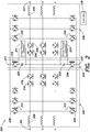
- the first switch 210 and the second switch 212 are 1200V Insulated-Gate Bipolar Transistors (IGBT); however, in other embodiments, the switches 210, 212 may be rated differently or different types of switches may be utilized (for example, the switches 210, 212 can be replaced with diodes if uni-directional power conversion in the PFC portion 202 is sufficient).
- the ninth switch 230 and the tenth switch 232 are 1200V IGBTs; however, in other embodiments, the switches 230, 232 may be rated differently or different types of switches may be utilized.
- the third switch 214, fourth switch 216, seventh switch 226, and eighth switch 228 are 600V IGBTs; however, in other embodiments, the switches 214, 216, 226, 228 may be rated differently or different types of switches may be utilized.
- Each of the switches 210-216, 226-232 may include an internal diode coupled between its collector and emitter.
- the fifth switch 218 and sixth switch 224 are 600V Metal-Oxide-Semiconductor Field-Effect Transistors (MOSFETs); however, in other embodiments, the switches 218, 224 may be rated differently or different types of switches (for example, IGBTs) may be utilized. Where the switches 218, 224 are implemented as MOSFETs, each of the switches 218, 224 may include an internal diode coupled between its drain and source.
- the source of the fifth switch 218 is coupled to the first DC bus 238.
- the drain of the fifth switch 218 is coupled to the first capacitor 220.
- the first capacitor 220 is coupled to the drain of the fifth switch 218 at a first connection, and is coupled to the collector of the fourth switch 216, the second capacitor 222, and the collector of the seventh switch 226 at a second connection.
- the first capacitor 220 is further coupled in parallel with the first shoot-through detector 221.
- the second capacitor 222 is coupled to the first capacitor 220, the collector of the fourth switch 216, and the collector of the seventh switch 226 at a first connection, and is coupled to the source of the sixth switch 224 at a second connection.
- the second capacitor 222 is further configured to be coupled in parallel with the second shoot-through detector 223.
- the source of the sixth switch 224 is coupled to the second capacitor 222, and the drain of the sixth switch 224 is coupled to the second DC bus 240.
- the collector of the seventh switch 226 is coupled to the first capacitor 220, the collector of the fourth switch 216, and the second capacitor 222.
- the emitter of the seventh switch 226 is coupled to the emitter of the eighth switch 228.
- the emitter of the eighth switch 228 is coupled to the emitter of the seventh switch 226.
- the collector of the eighth switch 228 is coupled to the emitter of the ninth switch 230, the collector of the tenth switch 232, and the output inductor 234.
- the controller 236 is configured to be communicatively coupled to a respective control terminal of one or more of the switches 210, 212, 214, 216, 218, 224, 226, 228, 230, 232.
- the first DC bus 238 is coupled to the collector of the first switch 210, the source of the fifth switch 218, the collector of the ninth switch 230, and the first backup power supply node 217.
- the second DC bus 240 is coupled to the emitter of the second switch 212, the drain of the sixth switch 224, the emitter of the tenth switch 232, and the second backup power supply node 225.
- one phase of the three-phase input power may be received at the first input 201.
- the controller 236 operates the first switch 210 and the third switch 214 as a boost converter to convert the one phase of the three-phase input power into converted DC power.
- the controller 236 also operates the first switch 210 and the third switch 214 to provide power factor correction at the first input 201.
- the converted DC power is provided to the first DC bus 238.
- the ninth switch 230 is operated by the controller 236 to convert DC power from the first DC bus 238 into regulated AC power.
- the regulated AC power is provided to the first output 207 via the output inductor 234.
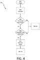
- the first shoot-through detector 221 may determine if the instantaneous voltage has continuously exceeded the delayed peak voltage measurement by more than a threshold amount for a threshold period of time.
- the threshold amount of time may be approximately 500 ns. If the instantaneous voltage has not continuously exceeded the delayed peak voltage measurement for a threshold amount of time (408 NO), then no shoot-through condition is detected (306 NO) and the process 400 ends by returning to 306 NO of the process 300. Otherwise (408 YES), the process 400 continues to act 410.
- a shoot-through detection signal is generated.
- the first shoot-through detector 221 may generate a signal indicating that the first capacitor 220 is experiencing a shoot-through condition (306 YES). The process 400 ends by returning to 306 YES of the process 300.
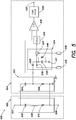
- the second input signal 538 may be implemented to provide a buffer value indicative of an amount by which the instantaneous voltage must exceed the delayed peak voltage for the shoot-through condition to be detected.
- the comparator 518 will output a signal indicating that a shoot-through condition is detected if, Vinstantaneous > Vpeak + Vbuffer where V instantaneous is a voltage measured at the non-inverting connection of the comparator 518, V peak is a most-recently-held peak voltage across the capacitor 502 held by the capacitor 532, and V buffer is a buffer voltage derived from the second input signal 538.
- one or more controllers may perform one or more of the operations discussed herein.
- the first shoot-through detector 221, the second shoot-through detector 223, the shoot-through detector 504, the controller 236, and the controller 612 are illustrated as discrete components, in some embodiments, a single controller may be configured to execute the functionality of each of the foregoing components.
- the controller 236 may be configured to execute the functionality of the shoot-through detectors 221, 223, 504, including detecting shoot-through in one or more capacitors.
- an embodiment of at least one of the shoot-through detectors 221, 223, 504 may be a component of the controller 236.
Landscapes
- Engineering & Computer Science (AREA)
- Power Engineering (AREA)
- Physics & Mathematics (AREA)
- General Physics & Mathematics (AREA)
- Business, Economics & Management (AREA)
- Emergency Management (AREA)
- Inverter Devices (AREA)
- Rectifiers (AREA)
Priority Applications (1)
| Application Number | Priority Date | Filing Date | Title |
|---|---|---|---|
| EP22177372.4A EP4071952A1 (de) | 2018-11-30 | 2019-11-12 | Erkennung von durchschlägen in stromrichtern |
Applications Claiming Priority (1)
| Application Number | Priority Date | Filing Date | Title |
|---|---|---|---|
| US16/205,684 US11050338B2 (en) | 2018-11-30 | 2018-11-30 | Detection of shoot-through in power converters |
Related Child Applications (1)
| Application Number | Title | Priority Date | Filing Date |
|---|---|---|---|
| EP22177372.4A Division EP4071952A1 (de) | 2018-11-30 | 2019-11-12 | Erkennung von durchschlägen in stromrichtern |
Publications (2)
| Publication Number | Publication Date |
|---|---|
| EP3661009A1 true EP3661009A1 (de) | 2020-06-03 |
| EP3661009B1 EP3661009B1 (de) | 2022-07-06 |
Family
ID=68581315
Family Applications (2)
| Application Number | Title | Priority Date | Filing Date |
|---|---|---|---|
| EP19208691.6A Active EP3661009B1 (de) | 2018-11-30 | 2019-11-12 | Erkennung von shoot-through in stromrichtern |
| EP22177372.4A Pending EP4071952A1 (de) | 2018-11-30 | 2019-11-12 | Erkennung von durchschlägen in stromrichtern |
Family Applications After (1)
| Application Number | Title | Priority Date | Filing Date |
|---|---|---|---|
| EP22177372.4A Pending EP4071952A1 (de) | 2018-11-30 | 2019-11-12 | Erkennung von durchschlägen in stromrichtern |
Country Status (3)
| Country | Link |
|---|---|
| US (1) | US11050338B2 (de) |
| EP (2) | EP3661009B1 (de) |
| CN (1) | CN111257703B (de) |
Citations (2)
| Publication number | Priority date | Publication date | Assignee | Title |
|---|---|---|---|---|
| US20130003429A1 (en) * | 2010-02-25 | 2013-01-03 | Mitsubishi Electric Corporation | Power conversion device |
| US20170149346A1 (en) * | 2014-06-27 | 2017-05-25 | Schneider Electric It Corporation | 3-level power topology |
Family Cites Families (5)
| Publication number | Priority date | Publication date | Assignee | Title |
|---|---|---|---|---|
| US8830637B2 (en) * | 2010-08-31 | 2014-09-09 | Texas Instruments Incorporated | Methods and apparatus to clamp overvoltages for alternating current systems |
| US10148188B2 (en) * | 2016-09-06 | 2018-12-04 | Fairchild Semiconductor Corporation | Clamp voltage detection and over-voltage protection for power supply topologies |
| US10164531B2 (en) * | 2017-02-15 | 2018-12-25 | Dialog Semiconductor (Uk) Limited | Adaptive control method for generating non overlapping time in output devices |
| US11152780B2 (en) * | 2017-08-31 | 2021-10-19 | Eaton Intelligent Power Limited | Adjustable speed drive with integrated solid-state circuit breaker and method of operation thereof |
| DE102018129909B4 (de) * | 2018-11-27 | 2020-12-31 | Danfoss Power Electronics A/S | Leistungselektronikeinrichtung |
-
2018
- 2018-11-30 US US16/205,684 patent/US11050338B2/en active Active
-
2019
- 2019-11-12 EP EP19208691.6A patent/EP3661009B1/de active Active
- 2019-11-12 EP EP22177372.4A patent/EP4071952A1/de active Pending
- 2019-11-29 CN CN201911203553.6A patent/CN111257703B/zh active Active
Patent Citations (2)
| Publication number | Priority date | Publication date | Assignee | Title |
|---|---|---|---|---|
| US20130003429A1 (en) * | 2010-02-25 | 2013-01-03 | Mitsubishi Electric Corporation | Power conversion device |
| US20170149346A1 (en) * | 2014-06-27 | 2017-05-25 | Schneider Electric It Corporation | 3-level power topology |
Also Published As
| Publication number | Publication date |
|---|---|
| CN111257703B (zh) | 2024-11-29 |
| US11050338B2 (en) | 2021-06-29 |
| EP4071952A1 (de) | 2022-10-12 |
| EP3661009B1 (de) | 2022-07-06 |
| US20200177069A1 (en) | 2020-06-04 |
| CN111257703A (zh) | 2020-06-09 |
Similar Documents
| Publication | Publication Date | Title |
|---|---|---|
| US10756567B2 (en) | Uninterruptible power supply device | |
| US9154000B2 (en) | Uninterruptible power supply apparatus including a control circuit that executes a first mode when supply of a first AC electric power from a commercial AC power supply is resumed at a time of discharge end | |
| US9762133B2 (en) | AC-DC converter with output power suppression | |
| EP3035513A2 (de) | Schaltnetzteil und verfahren zur steuerung der spannung eines massenkondensators darin | |
| US9024609B2 (en) | Circuit and method for providing hold-up time in a DC-DC converter | |
| US11088528B2 (en) | Arc detection circuit, switch system, power conditioner system and arc detection method | |
| US10340730B2 (en) | Uninterruptible power supply apparatus | |
| US11245337B2 (en) | Power supply device | |
| US11817738B2 (en) | Fault condition detection system and method | |
| CN108226839B (zh) | 一种变换器、霍尔传感器的异常检测方法及装置 | |
| US11271419B2 (en) | Uninterruptible power supply device | |
| US20160308390A1 (en) | Emergency dimming apparatus | |
| JP2008228494A (ja) | 系統連系用インバータ | |
| US12476631B2 (en) | Power supply device comprising a plurality of semiconductor switches and a mechanical switch connected in series | |
| EP3661009B1 (de) | Erkennung von shoot-through in stromrichtern | |
| US10958158B2 (en) | Controlling discharge of x-capacitance | |
| JP6994673B2 (ja) | 電力変換システム | |
| US20220140747A1 (en) | Power conversion apparatus | |
| US20250373057A1 (en) | Power supply and program for power supply | |
| US20250067814A1 (en) | Method and apparatus of performing failure detection on ac input voltage, and power supply system | |
| US20190081552A1 (en) | Electric power conversion system | |
| CN110071622A (zh) | 变频器的多功能预充电电路及其控制装置和方法,以及变频器 |
Legal Events
| Date | Code | Title | Description |
|---|---|---|---|
| PUAI | Public reference made under article 153(3) epc to a published international application that has entered the european phase |
Free format text: ORIGINAL CODE: 0009012 |
|
| STAA | Information on the status of an ep patent application or granted ep patent |
Free format text: STATUS: THE APPLICATION HAS BEEN PUBLISHED |
|
| AK | Designated contracting states |
Kind code of ref document: A1 Designated state(s): AL AT BE BG CH CY CZ DE DK EE ES FI FR GB GR HR HU IE IS IT LI LT LU LV MC MK MT NL NO PL PT RO RS SE SI SK SM TR |
|
| AX | Request for extension of the european patent |
Extension state: BA ME |
|
| STAA | Information on the status of an ep patent application or granted ep patent |
Free format text: STATUS: REQUEST FOR EXAMINATION WAS MADE |
|
| 17P | Request for examination filed |
Effective date: 20201203 |
|
| RBV | Designated contracting states (corrected) |
Designated state(s): AL AT BE BG CH CY CZ DE DK EE ES FI FR GB GR HR HU IE IS IT LI LT LU LV MC MK MT NL NO PL PT RO RS SE SI SK SM TR |
|
| STAA | Information on the status of an ep patent application or granted ep patent |
Free format text: STATUS: EXAMINATION IS IN PROGRESS |
|
| 17Q | First examination report despatched |
Effective date: 20210803 |
|
| RIC1 | Information provided on ipc code assigned before grant |
Ipc: H02M 7/487 20070101ALI20211221BHEP Ipc: H02M 5/458 20060101ALI20211221BHEP Ipc: H02M 1/38 20070101ALI20211221BHEP Ipc: H02M 1/32 20070101ALI20211221BHEP Ipc: H02H 7/122 20060101ALI20211221BHEP Ipc: H02H 7/10 20060101ALI20211221BHEP Ipc: H02J 9/06 20060101AFI20211221BHEP |
|
| GRAP | Despatch of communication of intention to grant a patent |
Free format text: ORIGINAL CODE: EPIDOSNIGR1 |
|
| STAA | Information on the status of an ep patent application or granted ep patent |
Free format text: STATUS: GRANT OF PATENT IS INTENDED |
|
| INTG | Intention to grant announced |
Effective date: 20220214 |
|
| GRAS | Grant fee paid |
Free format text: ORIGINAL CODE: EPIDOSNIGR3 |
|
| GRAA | (expected) grant |
Free format text: ORIGINAL CODE: 0009210 |
|
| STAA | Information on the status of an ep patent application or granted ep patent |
Free format text: STATUS: THE PATENT HAS BEEN GRANTED |
|
| AK | Designated contracting states |
Kind code of ref document: B1 Designated state(s): AL AT BE BG CH CY CZ DE DK EE ES FI FR GB GR HR HU IE IS IT LI LT LU LV MC MK MT NL NO PL PT RO RS SE SI SK SM TR |
|
| RAP3 | Party data changed (applicant data changed or rights of an application transferred) |
Owner name: SCHNEIDER ELECTRIC IT CORPORATION |
|
| REG | Reference to a national code |
Ref country code: AT Ref legal event code: REF Ref document number: 1503579 Country of ref document: AT Kind code of ref document: T Effective date: 20220715 Ref country code: CH Ref legal event code: EP |
|
| REG | Reference to a national code |
Ref country code: DE Ref legal event code: R096 Ref document number: 602019016647 Country of ref document: DE |
|
| REG | Reference to a national code |
Ref country code: IE Ref legal event code: FG4D |
|
| REG | Reference to a national code |
Ref country code: LT Ref legal event code: MG9D |
|
| REG | Reference to a national code |
Ref country code: NL Ref legal event code: MP Effective date: 20220706 |
|
| PG25 | Lapsed in a contracting state [announced via postgrant information from national office to epo] |
Ref country code: SE Free format text: LAPSE BECAUSE OF FAILURE TO SUBMIT A TRANSLATION OF THE DESCRIPTION OR TO PAY THE FEE WITHIN THE PRESCRIBED TIME-LIMIT Effective date: 20220706 Ref country code: RS Free format text: LAPSE BECAUSE OF FAILURE TO SUBMIT A TRANSLATION OF THE DESCRIPTION OR TO PAY THE FEE WITHIN THE PRESCRIBED TIME-LIMIT Effective date: 20220706 Ref country code: PT Free format text: LAPSE BECAUSE OF FAILURE TO SUBMIT A TRANSLATION OF THE DESCRIPTION OR TO PAY THE FEE WITHIN THE PRESCRIBED TIME-LIMIT Effective date: 20221107 Ref country code: NO Free format text: LAPSE BECAUSE OF FAILURE TO SUBMIT A TRANSLATION OF THE DESCRIPTION OR TO PAY THE FEE WITHIN THE PRESCRIBED TIME-LIMIT Effective date: 20221006 Ref country code: NL Free format text: LAPSE BECAUSE OF FAILURE TO SUBMIT A TRANSLATION OF THE DESCRIPTION OR TO PAY THE FEE WITHIN THE PRESCRIBED TIME-LIMIT Effective date: 20220706 Ref country code: LV Free format text: LAPSE BECAUSE OF FAILURE TO SUBMIT A TRANSLATION OF THE DESCRIPTION OR TO PAY THE FEE WITHIN THE PRESCRIBED TIME-LIMIT Effective date: 20220706 Ref country code: LT Free format text: LAPSE BECAUSE OF FAILURE TO SUBMIT A TRANSLATION OF THE DESCRIPTION OR TO PAY THE FEE WITHIN THE PRESCRIBED TIME-LIMIT Effective date: 20220706 Ref country code: FI Free format text: LAPSE BECAUSE OF FAILURE TO SUBMIT A TRANSLATION OF THE DESCRIPTION OR TO PAY THE FEE WITHIN THE PRESCRIBED TIME-LIMIT Effective date: 20220706 Ref country code: ES Free format text: LAPSE BECAUSE OF FAILURE TO SUBMIT A TRANSLATION OF THE DESCRIPTION OR TO PAY THE FEE WITHIN THE PRESCRIBED TIME-LIMIT Effective date: 20220706 |
|
| REG | Reference to a national code |
Ref country code: AT Ref legal event code: MK05 Ref document number: 1503579 Country of ref document: AT Kind code of ref document: T Effective date: 20220706 |
|
| PG25 | Lapsed in a contracting state [announced via postgrant information from national office to epo] |
Ref country code: PL Free format text: LAPSE BECAUSE OF FAILURE TO SUBMIT A TRANSLATION OF THE DESCRIPTION OR TO PAY THE FEE WITHIN THE PRESCRIBED TIME-LIMIT Effective date: 20220706 Ref country code: IS Free format text: LAPSE BECAUSE OF FAILURE TO SUBMIT A TRANSLATION OF THE DESCRIPTION OR TO PAY THE FEE WITHIN THE PRESCRIBED TIME-LIMIT Effective date: 20221106 Ref country code: HR Free format text: LAPSE BECAUSE OF FAILURE TO SUBMIT A TRANSLATION OF THE DESCRIPTION OR TO PAY THE FEE WITHIN THE PRESCRIBED TIME-LIMIT Effective date: 20220706 Ref country code: GR Free format text: LAPSE BECAUSE OF FAILURE TO SUBMIT A TRANSLATION OF THE DESCRIPTION OR TO PAY THE FEE WITHIN THE PRESCRIBED TIME-LIMIT Effective date: 20221007 |
|
| REG | Reference to a national code |
Ref country code: DE Ref legal event code: R097 Ref document number: 602019016647 Country of ref document: DE |
|
| PG25 | Lapsed in a contracting state [announced via postgrant information from national office to epo] |
Ref country code: SM Free format text: LAPSE BECAUSE OF FAILURE TO SUBMIT A TRANSLATION OF THE DESCRIPTION OR TO PAY THE FEE WITHIN THE PRESCRIBED TIME-LIMIT Effective date: 20220706 Ref country code: RO Free format text: LAPSE BECAUSE OF FAILURE TO SUBMIT A TRANSLATION OF THE DESCRIPTION OR TO PAY THE FEE WITHIN THE PRESCRIBED TIME-LIMIT Effective date: 20220706 Ref country code: DK Free format text: LAPSE BECAUSE OF FAILURE TO SUBMIT A TRANSLATION OF THE DESCRIPTION OR TO PAY THE FEE WITHIN THE PRESCRIBED TIME-LIMIT Effective date: 20220706 Ref country code: CZ Free format text: LAPSE BECAUSE OF FAILURE TO SUBMIT A TRANSLATION OF THE DESCRIPTION OR TO PAY THE FEE WITHIN THE PRESCRIBED TIME-LIMIT Effective date: 20220706 Ref country code: AT Free format text: LAPSE BECAUSE OF FAILURE TO SUBMIT A TRANSLATION OF THE DESCRIPTION OR TO PAY THE FEE WITHIN THE PRESCRIBED TIME-LIMIT Effective date: 20220706 |
|
| PLBE | No opposition filed within time limit |
Free format text: ORIGINAL CODE: 0009261 |
|
| STAA | Information on the status of an ep patent application or granted ep patent |
Free format text: STATUS: NO OPPOSITION FILED WITHIN TIME LIMIT |
|
| PG25 | Lapsed in a contracting state [announced via postgrant information from national office to epo] |
Ref country code: SK Free format text: LAPSE BECAUSE OF FAILURE TO SUBMIT A TRANSLATION OF THE DESCRIPTION OR TO PAY THE FEE WITHIN THE PRESCRIBED TIME-LIMIT Effective date: 20220706 Ref country code: EE Free format text: LAPSE BECAUSE OF FAILURE TO SUBMIT A TRANSLATION OF THE DESCRIPTION OR TO PAY THE FEE WITHIN THE PRESCRIBED TIME-LIMIT Effective date: 20220706 |
|
| 26N | No opposition filed |
Effective date: 20230411 |
|
| PG25 | Lapsed in a contracting state [announced via postgrant information from national office to epo] |
Ref country code: MC Free format text: LAPSE BECAUSE OF FAILURE TO SUBMIT A TRANSLATION OF THE DESCRIPTION OR TO PAY THE FEE WITHIN THE PRESCRIBED TIME-LIMIT Effective date: 20220706 Ref country code: AL Free format text: LAPSE BECAUSE OF FAILURE TO SUBMIT A TRANSLATION OF THE DESCRIPTION OR TO PAY THE FEE WITHIN THE PRESCRIBED TIME-LIMIT Effective date: 20220706 |
|
| REG | Reference to a national code |
Ref country code: CH Ref legal event code: PL |
|
| REG | Reference to a national code |
Ref country code: BE Ref legal event code: MM Effective date: 20221130 |
|
| PG25 | Lapsed in a contracting state [announced via postgrant information from national office to epo] |
Ref country code: LI Free format text: LAPSE BECAUSE OF NON-PAYMENT OF DUE FEES Effective date: 20221130 Ref country code: CH Free format text: LAPSE BECAUSE OF NON-PAYMENT OF DUE FEES Effective date: 20221130 |
|
| PG25 | Lapsed in a contracting state [announced via postgrant information from national office to epo] |
Ref country code: SI Free format text: LAPSE BECAUSE OF FAILURE TO SUBMIT A TRANSLATION OF THE DESCRIPTION OR TO PAY THE FEE WITHIN THE PRESCRIBED TIME-LIMIT Effective date: 20220706 Ref country code: LU Free format text: LAPSE BECAUSE OF NON-PAYMENT OF DUE FEES Effective date: 20221112 |
|
| PG25 | Lapsed in a contracting state [announced via postgrant information from national office to epo] |
Ref country code: IE Free format text: LAPSE BECAUSE OF NON-PAYMENT OF DUE FEES Effective date: 20221112 |
|
| PG25 | Lapsed in a contracting state [announced via postgrant information from national office to epo] |
Ref country code: BE Free format text: LAPSE BECAUSE OF NON-PAYMENT OF DUE FEES Effective date: 20221130 |
|
| PG25 | Lapsed in a contracting state [announced via postgrant information from national office to epo] |
Ref country code: IT Free format text: LAPSE BECAUSE OF FAILURE TO SUBMIT A TRANSLATION OF THE DESCRIPTION OR TO PAY THE FEE WITHIN THE PRESCRIBED TIME-LIMIT Effective date: 20220706 |
|
| PG25 | Lapsed in a contracting state [announced via postgrant information from national office to epo] |
Ref country code: HU Free format text: LAPSE BECAUSE OF FAILURE TO SUBMIT A TRANSLATION OF THE DESCRIPTION OR TO PAY THE FEE WITHIN THE PRESCRIBED TIME-LIMIT; INVALID AB INITIO Effective date: 20191112 |
|
| PG25 | Lapsed in a contracting state [announced via postgrant information from national office to epo] |
Ref country code: CY Free format text: LAPSE BECAUSE OF FAILURE TO SUBMIT A TRANSLATION OF THE DESCRIPTION OR TO PAY THE FEE WITHIN THE PRESCRIBED TIME-LIMIT Effective date: 20220706 |
|
| PG25 | Lapsed in a contracting state [announced via postgrant information from national office to epo] |
Ref country code: MK Free format text: LAPSE BECAUSE OF FAILURE TO SUBMIT A TRANSLATION OF THE DESCRIPTION OR TO PAY THE FEE WITHIN THE PRESCRIBED TIME-LIMIT Effective date: 20220706 |
|
| PG25 | Lapsed in a contracting state [announced via postgrant information from national office to epo] |
Ref country code: TR Free format text: LAPSE BECAUSE OF FAILURE TO SUBMIT A TRANSLATION OF THE DESCRIPTION OR TO PAY THE FEE WITHIN THE PRESCRIBED TIME-LIMIT Effective date: 20220706 |
|
| PG25 | Lapsed in a contracting state [announced via postgrant information from national office to epo] |
Ref country code: BG Free format text: LAPSE BECAUSE OF FAILURE TO SUBMIT A TRANSLATION OF THE DESCRIPTION OR TO PAY THE FEE WITHIN THE PRESCRIBED TIME-LIMIT Effective date: 20220706 |
|
| PG25 | Lapsed in a contracting state [announced via postgrant information from national office to epo] |
Ref country code: MT Free format text: LAPSE BECAUSE OF FAILURE TO SUBMIT A TRANSLATION OF THE DESCRIPTION OR TO PAY THE FEE WITHIN THE PRESCRIBED TIME-LIMIT Effective date: 20220706 |
|
| PGFP | Annual fee paid to national office [announced via postgrant information from national office to epo] |
Ref country code: DE Payment date: 20251126 Year of fee payment: 7 |
|
| PGFP | Annual fee paid to national office [announced via postgrant information from national office to epo] |
Ref country code: GB Payment date: 20251125 Year of fee payment: 7 |
|
| PGFP | Annual fee paid to national office [announced via postgrant information from national office to epo] |
Ref country code: FR Payment date: 20251124 Year of fee payment: 7 |