EP3659951A1 - Elastic roller, nip roller, and conveying device - Google Patents
Elastic roller, nip roller, and conveying device Download PDFInfo
- Publication number
- EP3659951A1 EP3659951A1 EP18837411.0A EP18837411A EP3659951A1 EP 3659951 A1 EP3659951 A1 EP 3659951A1 EP 18837411 A EP18837411 A EP 18837411A EP 3659951 A1 EP3659951 A1 EP 3659951A1
- Authority
- EP
- European Patent Office
- Prior art keywords
- roll
- layer
- elastomer
- longitudinal direction
- elastic
- Prior art date
- Legal status (The legal status is an assumption and is not a legal conclusion. Google has not performed a legal analysis and makes no representation as to the accuracy of the status listed.)
- Granted
Links
- 229920001971 elastomer Polymers 0.000 claims abstract description 110
- 239000000806 elastomer Substances 0.000 claims abstract description 95
- 239000010410 layer Substances 0.000 claims abstract description 83
- 238000007789 sealing Methods 0.000 claims abstract description 83
- 239000002344 surface layer Substances 0.000 claims abstract description 77
- 239000000126 substance Substances 0.000 claims abstract description 69
- 238000000034 method Methods 0.000 claims description 22
- 239000000758 substrate Substances 0.000 claims description 21
- 230000008569 process Effects 0.000 claims description 20
- 230000007246 mechanism Effects 0.000 claims description 13
- 238000003825 pressing Methods 0.000 claims description 13
- 230000007423 decrease Effects 0.000 claims description 6
- 239000000463 material Substances 0.000 description 31
- 238000012360 testing method Methods 0.000 description 18
- 239000005060 rubber Substances 0.000 description 15
- YCKRFDGAMUMZLT-UHFFFAOYSA-N Fluorine atom Chemical compound [F] YCKRFDGAMUMZLT-UHFFFAOYSA-N 0.000 description 10
- 239000011737 fluorine Substances 0.000 description 10
- 229910052731 fluorine Inorganic materials 0.000 description 10
- 230000008859 change Effects 0.000 description 9
- 238000000576 coating method Methods 0.000 description 9
- 239000011248 coating agent Substances 0.000 description 6
- 238000007654 immersion Methods 0.000 description 6
- 229920003051 synthetic elastomer Polymers 0.000 description 6
- 229920003002 synthetic resin Polymers 0.000 description 6
- 239000000057 synthetic resin Substances 0.000 description 6
- 239000005061 synthetic rubber Substances 0.000 description 6
- 230000000052 comparative effect Effects 0.000 description 5
- 238000011282 treatment Methods 0.000 description 5
- 238000010586 diagram Methods 0.000 description 4
- 230000000694 effects Effects 0.000 description 4
- QTBSBXVTEAMEQO-UHFFFAOYSA-N Acetic acid Chemical compound CC(O)=O QTBSBXVTEAMEQO-UHFFFAOYSA-N 0.000 description 3
- 230000004888 barrier function Effects 0.000 description 3
- 238000004140 cleaning Methods 0.000 description 3
- 239000003960 organic solvent Substances 0.000 description 3
- 229920005989 resin Polymers 0.000 description 3
- 239000011347 resin Substances 0.000 description 3
- XLYOFNOQVPJJNP-UHFFFAOYSA-N water Substances O XLYOFNOQVPJJNP-UHFFFAOYSA-N 0.000 description 3
- OCJBOOLMMGQPQU-UHFFFAOYSA-N 1,4-dichlorobenzene Chemical compound ClC1=CC=C(Cl)C=C1 OCJBOOLMMGQPQU-UHFFFAOYSA-N 0.000 description 2
- 229920000181 Ethylene propylene rubber Polymers 0.000 description 2
- XEEYBQQBJWHFJM-UHFFFAOYSA-N Iron Chemical compound [Fe] XEEYBQQBJWHFJM-UHFFFAOYSA-N 0.000 description 2
- 239000000853 adhesive Substances 0.000 description 2
- 230000001070 adhesive effect Effects 0.000 description 2
- 239000013043 chemical agent Substances 0.000 description 2
- 229940117389 dichlorobenzene Drugs 0.000 description 2
- 239000007788 liquid Substances 0.000 description 2
- 239000003921 oil Substances 0.000 description 2
- 230000002093 peripheral effect Effects 0.000 description 2
- 239000004033 plastic Substances 0.000 description 2
- 229920003023 plastic Polymers 0.000 description 2
- 229910001220 stainless steel Inorganic materials 0.000 description 2
- 239000010935 stainless steel Substances 0.000 description 2
- 238000012935 Averaging Methods 0.000 description 1
- 229920000459 Nitrile rubber Polymers 0.000 description 1
- 229920006311 Urethane elastomer Polymers 0.000 description 1
- 229920000122 acrylonitrile butadiene styrene Polymers 0.000 description 1
- 239000012790 adhesive layer Substances 0.000 description 1
- CQEYYJKEWSMYFG-UHFFFAOYSA-N butyl acrylate Chemical compound CCCCOC(=O)C=C CQEYYJKEWSMYFG-UHFFFAOYSA-N 0.000 description 1
- 230000007797 corrosion Effects 0.000 description 1
- 238000005260 corrosion Methods 0.000 description 1
- 238000013461 design Methods 0.000 description 1
- 238000009826 distribution Methods 0.000 description 1
- 230000002708 enhancing effect Effects 0.000 description 1
- 150000002148 esters Chemical class 0.000 description 1
- 239000012530 fluid Substances 0.000 description 1
- 239000010720 hydraulic oil Substances 0.000 description 1
- 229910052742 iron Inorganic materials 0.000 description 1
- 238000004519 manufacturing process Methods 0.000 description 1
- 239000002184 metal Substances 0.000 description 1
- 229910052751 metal Inorganic materials 0.000 description 1
- 239000007769 metal material Substances 0.000 description 1
- 239000002480 mineral oil Substances 0.000 description 1
- 235000010446 mineral oil Nutrition 0.000 description 1
- 239000000203 mixture Substances 0.000 description 1
- 238000005457 optimization Methods 0.000 description 1
- 239000011295 pitch Substances 0.000 description 1
- 239000002985 plastic film Substances 0.000 description 1
- 229920006255 plastic film Polymers 0.000 description 1
- 238000007747 plating Methods 0.000 description 1
- 229920000915 polyvinyl chloride Polymers 0.000 description 1
- 239000004800 polyvinyl chloride Substances 0.000 description 1
- 238000012545 processing Methods 0.000 description 1
- 238000009991 scouring Methods 0.000 description 1
- 229920002379 silicone rubber Polymers 0.000 description 1
- 239000004945 silicone rubber Substances 0.000 description 1
- 238000004513 sizing Methods 0.000 description 1
- 239000007787 solid Substances 0.000 description 1
Images


Classifications
-
- B—PERFORMING OPERATIONS; TRANSPORTING
- B65—CONVEYING; PACKING; STORING; HANDLING THIN OR FILAMENTARY MATERIAL
- B65H—HANDLING THIN OR FILAMENTARY MATERIAL, e.g. SHEETS, WEBS, CABLES
- B65H27/00—Special constructions, e.g. surface features, of feed or guide rollers for webs
-
- B—PERFORMING OPERATIONS; TRANSPORTING
- B65—CONVEYING; PACKING; STORING; HANDLING THIN OR FILAMENTARY MATERIAL
- B65H—HANDLING THIN OR FILAMENTARY MATERIAL, e.g. SHEETS, WEBS, CABLES
- B65H20/00—Advancing webs
- B65H20/02—Advancing webs by friction roller
-
- B—PERFORMING OPERATIONS; TRANSPORTING
- B65—CONVEYING; PACKING; STORING; HANDLING THIN OR FILAMENTARY MATERIAL
- B65H—HANDLING THIN OR FILAMENTARY MATERIAL, e.g. SHEETS, WEBS, CABLES
- B65H2301/00—Handling processes for sheets or webs
- B65H2301/40—Type of handling process
- B65H2301/44—Moving, forwarding, guiding material
- B65H2301/443—Moving, forwarding, guiding material by acting on surface of handled material
- B65H2301/4431—Moving, forwarding, guiding material by acting on surface of handled material by means with operating surfaces contacting opposite faces of material
- B65H2301/44318—Moving, forwarding, guiding material by acting on surface of handled material by means with operating surfaces contacting opposite faces of material between rollers
-
- B—PERFORMING OPERATIONS; TRANSPORTING
- B65—CONVEYING; PACKING; STORING; HANDLING THIN OR FILAMENTARY MATERIAL
- B65H—HANDLING THIN OR FILAMENTARY MATERIAL, e.g. SHEETS, WEBS, CABLES
- B65H2301/00—Handling processes for sheets or webs
- B65H2301/50—Auxiliary process performed during handling process
- B65H2301/51—Modifying a characteristic of handled material
- B65H2301/511—Processing surface of handled material upon transport or guiding thereof, e.g. cleaning
- B65H2301/5114—Processing surface of handled material upon transport or guiding thereof, e.g. cleaning coating
-
- B—PERFORMING OPERATIONS; TRANSPORTING
- B65—CONVEYING; PACKING; STORING; HANDLING THIN OR FILAMENTARY MATERIAL
- B65H—HANDLING THIN OR FILAMENTARY MATERIAL, e.g. SHEETS, WEBS, CABLES
- B65H2404/00—Parts for transporting or guiding the handled material
- B65H2404/10—Rollers
- B65H2404/18—Rollers composed of several layers
-
- B—PERFORMING OPERATIONS; TRANSPORTING
- B65—CONVEYING; PACKING; STORING; HANDLING THIN OR FILAMENTARY MATERIAL
- B65H—HANDLING THIN OR FILAMENTARY MATERIAL, e.g. SHEETS, WEBS, CABLES
- B65H2601/00—Problem to be solved or advantage achieved
- B65H2601/50—Diminishing, minimizing or reducing
- B65H2601/52—Diminishing, minimizing or reducing entities relating to handling machine
Definitions
- the present invention relates to an elastic roll, and a nip roll and a conveyance device using the elastic roll.
- Web substrates such as paper and a plastic film may be subjected to various chemical solution treatments.
- the treatments include a process of immersing a substrate through a plating bath to electroplate the substrate and a wet coating process of applying a chemical solution.
- the examples also include a process of removing the chemical solution remaining on the substrate that has been subjected to the wet coating process and a wet cleaning process of using water or a cleaning fluid, for example, to clean a web substrate.
- wet coating process and the wet cleaning process as a whole are called "wet conveying process”.
- a web substrate is rarely completed as a product while being immersed in a chemical solution, and is commonly completed as a product under dry conditions.
- the web substrate that has been subjected to the wet conveying process is dried after removing the chemical solution therefrom, and is conveyed to the subsequent process. Outlines thereof will be described with reference to FIG. 6 illustrating one example from an exit of the wet conveying process to the process of being dried.
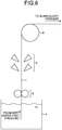
- FIG. 6 is a schematic diagram in which the web substrate is conveyed from the exit of the wet conveying process and is dried.
- the web substrate 1 that has been subjected to chemical solution treatment in the wet conveying process 4 is conveyed while carrying the chemical solution used in the wet conveying process 4. This carried chemical solution is scraped and removed by drain rolls 2.
- the web substrate 1 is dried by a drier 3, and is conveyed via a guide roll 5 to the subsequent process.
- a configuration of nipping with elastic rolls is preferably used therefor.
- Each elastic roll is required to have a plurality of properties such as suitable flexibility, durability to chemical solutions to be used, and wear resistance at the same time, and thus is generally designed using an elastomer having a multilayer structure such that needed functions are obtained at needed positions.
- Patent Literature 1 describes a configuration of a common multilayer structure elastic roll as a conventional art. A structure thereof is illustrated in FIG. 7(a) .
- a rubber elastic body 302 is wound around a shaft 301, and a synthetic resin layer 303 is coated on the outer periphery thereof.
- the synthetic resin layer 303 can have durability to chemical solutions, and also have needed flexibility imparted by the rubber elastic body layer 302.
- the rubber elastic body layer 302 is exposed at both ends of the roll, and the rubber elastic body layer 302 will be damaged from these exposed portions when a chemical solution that affects the rubber elastic body 302 is used.
- the rubber elastic body layer 302 is coated up to both end surfaces thereof with the synthetic resin layer 303 and also coating members 304 are fixed thereon as illustrated in FIG. 7(b) , whereby damage from both end surfaces thereof is prevented from developing.
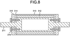
- Patent Literature 2 proposes a roll including an elastic body layer 312 formed on an outer peripheral portion of a roll core 311 and a mold-release layer 313 formed on an outer peripheral portion of the elastic body layer 312 and having a gas barrier property. A structure thereof is illustrated in FIG. 8 .
- fixing plates 315 having a gas barrier property and configured to fix sealing plates 314 are provided. With this configuration, outgas from the elastic body layer 312 is prevented from leaking outside.
- Patent Literature 1 when adhesiveness of the synthetic resin layer 303 to the shaft material is poor, entry of the chemical solution from between the synthetic resin layer 303 and the shaft 301 cannot be prevented. Furthermore, the structure thereof cannot increase force of bringing the coating member 304 into tight contact therewith, and thus sealing performance thereof is low. Consequently, when a material having low durability to the chemical solution is used as the elastic body layer 302 on a side closer to an inner layer, the inner layer is highly likely to be damaged by the chemical solution.
- the mold-release layer 313 and the sealing plates 314 are different members, and thus the positions of the fixing plates 315 vary depending on how the sealing plates 314 are compressed even if fastening forces of bolts 316 are increased in order to bring the sealing plate 314 into tight contact. Consequently, variations arise in compressing force of the elastic layer 312 in a roll circumferential direction, which makes it difficult to achieve uniform sealing and also makes it difficult to prevent entry of the chemical solution.
- an object of the present invention is to enable materials for an inner-layer elastic body to be selected according to various functions without considering durability to chemical solutions, and to provide an elastic roll that can satisfy required functions such as chemical resistance and roll hardness at a high level.
- An elastic roll of the present invention to solve the problem described above includes: a roll core; an inner-layer laminate covering an outer-peripheral surface of the roll core parallel to a roll longitudinal direction; a surface-layer elastomer including a tubular portion covering an outer-peripheral surface of the inner-layer laminate, and edge portions connected to the tubular portion, covering both end surfaces of the inner-layer laminate orthogonal to the roll longitudinal direction, and arranged in a manner being in contact with the roll core; and end-portion sealing structural bodies configured to press the edge portions of the surface-layer elastomer against the roll core.
- a nip roll of the present invention is the elastic roll of the present invention is used to drain a chemical solution carried by conveyance of a web substrate in a process of bringing the chemical solution into contact with the web substrate.
- the inner-layer laminate is formed of an elastomer, and an elastomer forming the surface-layer elastomer is formed with a material having hardness higher than that of the elastomer forming the inner-layer laminate and also having higher resistance to the chemical solution.
- a conveyance device of the present invention includes a process of bringing a chemical solution into contact with a web substrate, and a nipping mechanism.
- a nip roll used for the nipping mechanism is the nip roll of the present invention.
- the "chemical solution” refers to water, oils, organic solvents, other liquid chemical agents in general, and liquid mixtures thereof, or a solution in which a solid chemical agent is dissolved.
- the elastic roll that enables high-level optimization of functions such as chemical resistance and wear resistance required to the roll surface and functions such as flexibility required to the elastic body can be provided.
- the nip roll having high quality and long life, and the conveyance device using the nip roll can be provided.
- FIG. 1 is a sectional view illustrating main components according to an embodiment in which an elastic roll of the present invention is used as a nip roll.
- a nip roll 20 includes: a roll core 21; an inner-layer laminate 22 covering an outer-peripheral surface of the roll core 21 parallel to a roll longitudinal direction; a surface-layer elastomer 23 having a tubular portion 23a covering an outer-peripheral surface of the inner-layer laminate 22 and edge portions 23b connected to the tubular portion 23a, covering both end surfaces of the inner-layer laminate 22 orthogonal to the roll longitudinal direction, and arranged in a manner being in contact with the roll core 21; and end-portion sealing structural bodies 24 configured to press the edge portions 23b of the surface-layer elastomer 23 against the roll core 21.
- the inner-layer laminate 22 is wound.
- the surface-layer elastomer 23 is wound so as to cover the outer-peripheral surface of the inner-layer laminate 22 and both end surfaces thereof in the roll longitudinal direction.
- the edge portions 23b of the surface-layer elastomer 23 are in contact with the roll core 21.
- the edge portions 23b of the surface-layer elastomer 23 that are in contact with the roll core 21 are pressed against the roll core 21 by the end-portion sealing structural bodies 24.
- the roll core 21 generally has a cylindrical shape on both ends of which shafts configured to serve as bearing fitted portions are formed, but may have various shapes depending on functions required to the roll and intended use, for example.
- various structures may be used.
- various materials such as plastic and metal may be used.
- metallic materials such as iron and stainless steel are often used in general.
- Stainless steel excellent in corrosion resistance is preferably used particularly when it is used in a process using a chemical solution.
- the inner-layer laminate 22 wound around the outer-peripheral surface of the roll core 21 is often bonded onto the roll core 21 with adhesive in general, and thus a material having adhesiveness to the material of the roll core 21 is preferably used therefor.
- a plastic or an elastomer in various types may be appropriately selected to be used according to required functions.
- ethylene propylene rubber, silicone rubber, urethane rubber, or laminated rubber thereof or the like that enables the inner-layer laminate 22 to have lower hardness can be used.
- polyvinyl chloride or ABS resin for example, for the inner-layer laminate 22 enables a roll having higher hardness to be provided while reducing the volume of the inner-layer laminate 22.
- the surface-layer elastomer 23 covering the outer-peripheral surface and both end surfaces of the inner-layer laminate 22 is preferably bonded onto the inner-layer laminate 22, and is more preferably bonded also onto the roll core 21.
- a material thereof is selected appropriately according to functions required of a surface of the nip roll 20. Consequently, when the adhesiveness of the surface-layer elastomer 23 to the inner-layer laminate 22 is poor, it is preferable to change the material of the inner-layer laminate 22. Adhesiveness is determined generally depending on compatibility with each other among the surface-layer elastomer 23, the inner-layer laminate 22, and an adhesive.
- the material should be selected such that the functions required of the nip roll 20 are implemented to the greatest extent possible at the highest priority.
- a material having excellent adhesiveness to the material of the surface-layer elastomer 23 thus selected only needs to be selected as the material of inner-layer laminate 22.
- Pressure uniformity in the roll width direction that is one of properties of the nip roll 20 tends to be more excellent when the hardness of the whole laminate wound around the outer periphery of the roll core is lower.
- the surface-layer elastomer 23 that is brought into direct contact with the web substrate and the chemical solution is required to have high resistance to the chemical solution, options for the material are limited.
- the hardness of the whole laminate can be adjusted over a wide range by setting the hardness of the elastomer forming the inner-layer laminate 22 to be lower than that of the elastomer forming the surface-layer elastomer 23.
- a material that is not easily eroded by the chemical solution to be used is preferably used for the surface-layer elastomer 23.
- ethylene propylene rubber is not suitable under environments in which mineral oil adheres thereto
- nitrile rubber is not suitable under environments in which phosphoric ester-based hydraulic oil adheres thereto.
- an organic solvent such as butyl acrylate, acetic acid, or dichlorobenzene that tends to erode many materials adheres thereto, room for choice for materials is significantly limited, and thus the choice has to be made considering, at high priority, that the material has resistance to the chemical solution to be used.
- a structure in which the edge portions 23b of the surface-layer elastomer 23 are strongly pressed against the roll core 21 by the end-portion sealing structural bodies 24.
- the roll core 21 is a member having high stiffness, and thus a problem in which pressing force disperses and the sealing performance accordingly decreases can be avoided.
- any structure may be used if the function of pressing the edge portions 23b against the roll core 21 is implemented.
- a ring-shaped member having an inside diameter smaller than the outside diameter of the edge portions 23b may be attached, or a structure of inserting a cylindrical member the inside diameter of which is tapered may be used.
- a structure may be used in which the end-portion sealing structural body 24 includes a sealing member and a pressing mechanism, the pressing mechanism is configured to press the sealing member against the roll core 21, and the sealing member is configured to press the edge portions 23b against the roll core 21.
- this structure include a structure commonly called "hose band” for clamping with a band-shaped structural body the inside diameter of which decreases when a screw is tightened.
- the band-shaped structural body corresponds to the sealing member, and the screw corresponds to the pressing mechanism.
- the material used for the end-portion sealing structural bodies 24 is preferably a material having resistance to the chemical solution to be used.
- the outer shape of the surface-layer elastomer 23 is a flat cylindrical shape.
- the outside diameter thereof may be a radial crown shape, may be a shape having end portions that are tapered to a certain extent to reduce the outside diameter at both ends (hereinafter, called “end-portion tapered shape”), or may be a shape having such steps that the largest outside diameter of the end-portion sealing structural bodies 24 is not larger than the outside diameter of the edge portions 23b (hereinafter, called "grooved shape").
- the inner-layer laminate 22 may have a shape in various types such as the radial crown shape, the end-portion tapered shape, the grooved shape.
- FIGS. 2 are a sectional view ( FIG. 2(a) ) illustrating main components of another embodiment in which the elastic roll of the present invention is used as a nip roll and a partially enlarged view ( FIG. 2(b) ) of the portion surrounded by a black circle in FIG. 2(a) .
- This nip roll 20A has a configuration in which steps 211 are formed on outer-peripheral surfaces of a roll core 21A at portions that are not covered by the inner-layer laminate 22 such that the diameter of a roll core 21A decreases toward end portions thereof.
- edge portions 23b of a surface-layer elastomer 23A covering both end surfaces of the inner-layer laminate 22 also cover stepped surfaces of the roll core 21, and are in contact with the roll core 21.
- end-portion sealing structural bodies 24A are attached, and each end-portion sealing structural body 24A includes a sealing member 241 and pressing mechanisms 242.
- the sealing member 241 is pressed by the pressing mechanisms 242 such as typically bolts against the roll core 21 in the roll longitudinal direction.
- the sealing members 241 press both end portions of the surface-layer elastomer 23 covering both end surfaces of the inner-layer laminate 22, which are the edge portions 23b covering the stepped surfaces of the roll core 21, against the stepped surfaces of the roll core 21 in the roll longitudinal direction.
- pressing force against the stepped surfaces of the roll core 21A with the surface-layer elastomer 23A is securely applied as described above.
- the chemical solution is prevented from entering from a gap between the surface-layer elastomer 23A and the roll core 21A.
- end-portion sealing structural bodies 24B are structured to press edge portions 23b of a surface-layer elastomer 23B against stepped surfaces of the roll core 21B.
- the end-portion sealing structural bodies 24B have the same configuration as that of the end-portion sealing structural bodies 24A.
- the thickness h3 of the edge portion 23b in the roll longitudinal direction is greater than the height h4 of the corresponding step 211 by a length of d as illustrated in FIG. 2(b) when these portions are not pressed by the corresponding sealing member 241.
- the sealing member 241 compresses the surface-layer elastomer 23A while being in tight contact with the roll core 21.
- fixing plates 315 are pressed against a base 311 by fixing members 316, whereby adhesion between each sealing plate 314 and an elastic layer 312 is enhanced to obtain a sealing effect.
- the positions of the fixing plates 315 vary depending on how the sealing plates 314 are compressed, variations arise in compressing force of the elastic layer 312 in the roll circumferential direction, which makes it difficult to achieve uniform sealing.
- the protruding length d of the edge portion 23b can provide sufficient adhesion between the surface-layer elastomer 23 and the roll core 21.
- the protruding length d is preferably 0.3 mm or more.
- the upper limit of the protruding length d is not limited to a particular value.
- the protruding length d may be set within a range that enables the sealing member 241 to come into tight contact with the contact surface 212 of the roll core 21A while being pressed in the roll longitudinal direction, and can be appropriately determined according to the material of the surface-layer elastomer 23A and the compressing force in the roll longitudinal direction.
- the maximum outside diameter R1 of the sealing member 241 be set smaller than the outside diameter R2 of the surface-layer elastomer 23A (i.e., the size of the sealing member 241 be set such that its profile projected in the roll longitudinal direction is contained inside the outermost periphery of the surface-layer elastomer 23A in a plane orthogonal to the roll longitudinal direction) because this setting enables the nip roll 20A to be used also for a nip system to be nipped having a roll surface length that is greater than the nip roll surface length h5.
- edge portions 23b of the surface-layer elastomer 23A bulge due to compressing force applied by the end-portion sealing structural bodies 24A, and accordingly contact pressure against a roll to be nipped rises locally.
- FIGS. 4 are sectional views illustrating main components according to another embodiment in which the elastic roll of the present invention is used as a nip roll.
- FIG. 4(a) illustrates a state in which sealing members 241D are not pressed in the roll longitudinal direction against stepped surfaces 211 of a roll core 21D
- FIG. 4(b) illustrates a state in which the sealing members 241D are pressed.
- the sealing members 241D of the nip roll 20D illustrated in FIGS. 4 are members obtained by forming, on outer peripheries of the sealing members 241 of the nip roll 20A illustrated in FIGS. 2 , annular projections 243 each protruding toward the surface-layer elastomer 24A.
- the inside diameter R8 of the projections 243 is set larger than the outside diameter R7 of the steps 211, and the sealing members 241D are structured to push the surface-layer elastomer 23D such that it is dented by the length of the projections 243 when the inner walls 244 thereof are in tight contact with the contact surfaces 212 of the roll core 21. This is preferable because adhesion between the surface-layer elastomer 23D and the roll core 21D can be further increased.
- a gap adjusting member such as a shim is inserted between each sealing member 241D and the roll core 21D, the pushing length of the corresponding projection 243 into the surface-layer elastomer 23D can be adjusted, whereby adhesion between the surface-layer elastomer 23D and the roll core 21D can be adjusted. Furthermore, in the nip roll 20D, by the protruding length of the projection 243, the corresponding end surface of the surface-layer elastomer 23D can be pushed more than the corresponding contact surface 212 of the roll core 21D can. This eliminates the need of processing for accurately adjusting the positional relation between the contact surface 212 of the roll core 21D and the end surface of the surface-layer elastomer 23D, thereby facilitating design and manufacture of the roll.
- FIGS. 5 are sectional views illustrating main components according to still another embodiment in which the elastic roll of the present invention is used as a nip roll.
- FIG. 5(a) illustrates a state in which sealing members 241E are not yet pressed in the roll longitudinal direction against stepped surfaces of a roll core 21E
- FIG. 5(b) illustrates a state in which the sealing members 241E are pressed.
- the thickness h3 of edge portions 23b in the roll longitudinal direction is smaller than the height h4 of steps 211. Consequently, on surfaces of the steps 211 of the roll core 21E parallel to the roll longitudinal direction, exposed areas that are not covered by the surface-layer elastomer 23E are present.
- the innermost diameter R8 of projections 243E of the sealing members 241E is the same as the outside diameter R7 of the steps 211, and the projection 243E of each sealing member 241E is structured to press the corresponding edge portion 23b of the surface-layer elastomer 23E in the roll longitudinal direction when the corresponding exposed area of the roll core 21E and an inner-peripheral portion of the projection 243E are fitted together.
- This facilitates centering adjustment between the corresponding end-portion sealing structural body 24E and the roll core 21E, and thus the concentricity between the end-portion sealing structural body 24E and the roll core 21E can be increased, and eccentricity of the roll can be reduced.
- nip rolls 20, 20A, 20B, 20D, and 20E in which the elastic roll of the present invention is used can prevent the inner-layer laminate 22 from being eroded by the chemical solution and the like to be used.
- these nip rolls as drain rolls in a web conveyance device for the purpose of chemical solution treatment, the functions thereof can be implemented stably for a long period of time.
- the surface-layer elastomers 23 to 23E exert resistance to the chemical solution and the like, the need of requiring resistance to the chemical solution and the like of the inner-layer laminate 22 is eliminated.
- an optimum material for the inner-layer laminate 22 can be selected in consideration of properties such as roll hardness, and the range of choice for materials of the inner-layer laminate 22 is extended.
- the edge portions 23b of the surface-layer elastomers 23 to 23E are pressed by the end-portion sealing structural bodies 24 to 24E against the roll cores 21 to 21E, respectively, which eliminates the need of considering adhesiveness between each of the surface-layer elastomers 23 to 23E and the corresponding one of the roll cores 21 to 21E.
- an optimum material for the surface-layer elastomers 23 to 23E can be selected in consideration of properties such as chemical-solution resistance, and also the range of choice for materials of surface-layer elastomers 23 to 23E is extended. Consequently, the elastic roll of the present invention can achieve high-level compatibility of required functions such as roll hardness and durability to chemical solutions that generally conflict with each other.
- the elastic roll of the present invention is used as a nip roll.
- the present invention is not limited to these cases, and the elastic roll may be used as a coating roll, a laminate press roll, a conveyance roll, a sizing roll, a mangle roll, a scouring roll, a touch roll, and an ink roll, for example.
- volume change of the nip roll 20D between before and after the test was smaller than 1%.
- the volume change was calculated by the following formula after determining the volumes of an elastomer portion before and after the test.
- Volume change % Volume of elastomer portion after test ⁇ Volume of elastomer portion before test / Volume of elastomer portion before test ⁇ 100
- the cross-sectional area of the elastomer portion was determined based on the average outside diameter of the surface-layer elastomer and the outside diameter of the roll-core, and a product of the cross-sectional area of the elastomer portion and the length of the surface-layer elastomer in the roll longitudinal direction was obtained as the volume of the elastomer portion (the surface-layer elastomer and the inner-layer laminate).
- the average outside diameter of the surface-layer elastomer was obtained by measuring outside diameters thereof at pitches into which the length thereof in
- the volume change between before and after the test was smaller than 1%.
- Example 1 With the nip roll 20 illustrated in FIG. 1 , a test was conducted using the following roll configuration under the same immersion conditions as in Example 1.
- the surface-layer elastomer had sufficient resistance to the chemical solution to be used.
- the used chemical solution did not enter the inner-layer laminate, and consequently the volume change was reduced to be smaller than 1%.
- Example 2 The same test as in Example 1 except that the end-portion sealing structural bodies were removed was conducted, and consequently the volume change exceeded 5%.
- the present invention is highly preferable as an elastic nip roll used in a conveyance device configured to subject a web substrate to chemical solution treatment.
- the application range thereof is not limited to these.
Abstract
Description
- The present invention relates to an elastic roll, and a nip roll and a conveyance device using the elastic roll.
- Web substrates such as paper and a plastic film may be subjected to various chemical solution treatments. Examples of the treatments include a process of immersing a substrate through a plating bath to electroplate the substrate and a wet coating process of applying a chemical solution. The examples also include a process of removing the chemical solution remaining on the substrate that has been subjected to the wet coating process and a wet cleaning process of using water or a cleaning fluid, for example, to clean a web substrate. Hereinafter, the wet coating process and the wet cleaning process as a whole are called "wet conveying process".
- A web substrate is rarely completed as a product while being immersed in a chemical solution, and is commonly completed as a product under dry conditions. The web substrate that has been subjected to the wet conveying process is dried after removing the chemical solution therefrom, and is conveyed to the subsequent process. Outlines thereof will be described with reference to
FIG. 6 illustrating one example from an exit of the wet conveying process to the process of being dried.FIG. 6 is a schematic diagram in which the web substrate is conveyed from the exit of the wet conveying process and is dried. Theweb substrate 1 that has been subjected to chemical solution treatment in the wet conveying process 4 is conveyed while carrying the chemical solution used in the wet conveying process 4. This carried chemical solution is scraped and removed bydrain rolls 2. Subsequently, theweb substrate 1 is dried by adrier 3, and is conveyed via aguide roll 5 to the subsequent process. At this time, because thedrain rolls 2 can increase a draining efficiency by applying contact pressure to the whole of theweb substrate 1 in its width direction, a configuration of nipping with elastic rolls is preferably used therefor. Each elastic roll is required to have a plurality of properties such as suitable flexibility, durability to chemical solutions to be used, and wear resistance at the same time, and thus is generally designed using an elastomer having a multilayer structure such that needed functions are obtained at needed positions. -
Patent Literature 1 describes a configuration of a common multilayer structure elastic roll as a conventional art. A structure thereof is illustrated inFIG. 7(a) . A rubberelastic body 302 is wound around ashaft 301, and asynthetic resin layer 303 is coated on the outer periphery thereof. With this configuration, thesynthetic resin layer 303 can have durability to chemical solutions, and also have needed flexibility imparted by the rubberelastic body layer 302. However, the rubberelastic body layer 302 is exposed at both ends of the roll, and the rubberelastic body layer 302 will be damaged from these exposed portions when a chemical solution that affects the rubberelastic body 302 is used. In the invention ofPatent Literature 1, in order to prevent such damage, the rubberelastic body layer 302 is coated up to both end surfaces thereof with thesynthetic resin layer 303 and also coatingmembers 304 are fixed thereon as illustrated inFIG. 7(b) , whereby damage from both end surfaces thereof is prevented from developing. -
Patent Literature 2 proposes a roll including anelastic body layer 312 formed on an outer peripheral portion of aroll core 311 and a mold-release layer 313 formed on an outer peripheral portion of theelastic body layer 312 and having a gas barrier property. A structure thereof is illustrated inFIG. 8 . In order to obtain the gas barrier property on both end surfaces of theelastic body layer 312,fixing plates 315 having a gas barrier property and configured to fixsealing plates 314 are provided. With this configuration, outgas from theelastic body layer 312 is prevented from leaking outside. -
- Patent Literature 1: Japanese Patent Application Laid-open No.
2000-330374 - Patent Literature 2: Japanese Patent Application Laid-open No.
2007-193059 - In the configuration disclosed in
Patent Literature 1, when adhesiveness of thesynthetic resin layer 303 to the shaft material is poor, entry of the chemical solution from between thesynthetic resin layer 303 and theshaft 301 cannot be prevented. Furthermore, the structure thereof cannot increase force of bringing thecoating member 304 into tight contact therewith, and thus sealing performance thereof is low. Consequently, when a material having low durability to the chemical solution is used as theelastic body layer 302 on a side closer to an inner layer, the inner layer is highly likely to be damaged by the chemical solution. - In the configuration disclosed in
Patent Literature 2, the mold-release layer 313 and thesealing plates 314 are different members, and thus the positions of thefixing plates 315 vary depending on how thesealing plates 314 are compressed even if fastening forces ofbolts 316 are increased in order to bring thesealing plate 314 into tight contact. Consequently, variations arise in compressing force of theelastic layer 312 in a roll circumferential direction, which makes it difficult to achieve uniform sealing and also makes it difficult to prevent entry of the chemical solution. - As described above, in the conventional art, because entry of a chemical solution into the inner layer cannot be prevented completely, there are problems in which a material having low durability to the chemical solution cannot be used for the inner layer or life decreases when the material is used. Consequently, room for choice for materials is limited, and it is difficult to provide a configuration that can satisfy the required functions at a high level.
- In view of the problems in the conventional art, an object of the present invention is to enable materials for an inner-layer elastic body to be selected according to various functions without considering durability to chemical solutions, and to provide an elastic roll that can satisfy required functions such as chemical resistance and roll hardness at a high level.
- An elastic roll of the present invention to solve the problem described above includes: a roll core; an inner-layer laminate covering an outer-peripheral surface of the roll core parallel to a roll longitudinal direction; a surface-layer elastomer including a tubular portion covering an outer-peripheral surface of the inner-layer laminate, and edge portions connected to the tubular portion, covering both end surfaces of the inner-layer laminate orthogonal to the roll longitudinal direction, and arranged in a manner being in contact with the roll core; and end-portion sealing structural bodies configured to press the edge portions of the surface-layer elastomer against the roll core.
- A nip roll of the present invention is the elastic roll of the present invention is used to drain a chemical solution carried by conveyance of a web substrate in a process of bringing the chemical solution into contact with the web substrate. The inner-layer laminate is formed of an elastomer, and an elastomer forming the surface-layer elastomer is formed with a material having hardness higher than that of the elastomer forming the inner-layer laminate and also having higher resistance to the chemical solution.
- A conveyance device of the present invention includes a process of bringing a chemical solution into contact with a web substrate, and a nipping mechanism. A nip roll used for the nipping mechanism is the nip roll of the present invention.
- In the present invention, the "chemical solution" refers to water, oils, organic solvents, other liquid chemical agents in general, and liquid mixtures thereof, or a solution in which a solid chemical agent is dissolved. Advantageous Effects of Invention
- According to the present invention, the elastic roll that enables high-level optimization of functions such as chemical resistance and wear resistance required to the roll surface and functions such as flexibility required to the elastic body can be provided.
- Furthermore, with the elastic roll of the present invention, the nip roll having high quality and long life, and the conveyance device using the nip roll can be provided.
-
-
FIG. 1 is a sectional view illustrating main components according to an embodiment in which the present invention is applied to a nip roll. -
FIGS. 2 are sectional views illustrating main components according to another embodiment in which the present invention is applied to the nip roll. -
FIG. 3 is a sectional view illustrating main components according to another embodiment in which the present invention is applied to the nip roll. -
FIGS. 4 are sectional views illustrating main components according to another embodiment in which the present invention is applied to the nip roll, including a sectional view (FIG. 4(a) ) illustrating a state in which sealing members are not pressed and a sectional view (FIG. 4(b) ) illustrating a state in which the sealing members are pressed. -
FIGS. 5 are sectional views illustrating main components according to another embodiment in which the present invention is applied to the nip roll, including a sectional view (FIG. 5(a) ) illustrating a state in which sealing members are not pressed and a sectional view (FIG. 5(b) ) illustrating a state in which the sealing members are pressed. -
FIG. 6 is a schematic diagram illustrating one example of a vicinity of an exit of a wet conveying process. -
FIGS. 7 are diagrams illustrating main components of elastic rolls disclosed inPatent Literature 1, includingFIG. 7(a) illustrating a conventional art inPatent Literature 1 andFIG. 7(b) illustrating a technique ofPatent Literature 1. -
FIG. 8 is a diagram illustrating main components of an elastic roll disclosed inPatent Literature 2. - Cases in which examples of embodiments of the present invention are applied to a nip roll will now be described with reference to the drawings.
-
FIG. 1 is a sectional view illustrating main components according to an embodiment in which an elastic roll of the present invention is used as a nip roll. Anip roll 20 includes: aroll core 21; an inner-layer laminate 22 covering an outer-peripheral surface of theroll core 21 parallel to a roll longitudinal direction; a surface-layer elastomer 23 having atubular portion 23a covering an outer-peripheral surface of the inner-layer laminate 22 andedge portions 23b connected to thetubular portion 23a, covering both end surfaces of the inner-layer laminate 22 orthogonal to the roll longitudinal direction, and arranged in a manner being in contact with theroll core 21; and end-portion sealingstructural bodies 24 configured to press theedge portions 23b of the surface-layer elastomer 23 against theroll core 21. - Around the outer-peripheral surface of the
roll core 21 except both end portions thereof in the roll longitudinal direction, the inner-layer laminate 22 is wound. The surface-layer elastomer 23 is wound so as to cover the outer-peripheral surface of the inner-layer laminate 22 and both end surfaces thereof in the roll longitudinal direction. Theedge portions 23b of the surface-layer elastomer 23 are in contact with theroll core 21. Theedge portions 23b of the surface-layer elastomer 23 that are in contact with theroll core 21 are pressed against theroll core 21 by the end-portion sealingstructural bodies 24. - The
roll core 21 generally has a cylindrical shape on both ends of which shafts configured to serve as bearing fitted portions are formed, but may have various shapes depending on functions required to the roll and intended use, for example. Similarly, as an internal structure thereof, various structures may be used. As a material thereof, various materials such as plastic and metal may be used. However, from a viewpoint of durability, metallic materials such as iron and stainless steel are often used in general. Stainless steel excellent in corrosion resistance is preferably used particularly when it is used in a process using a chemical solution. - The inner-
layer laminate 22 wound around the outer-peripheral surface of theroll core 21 is often bonded onto theroll core 21 with adhesive in general, and thus a material having adhesiveness to the material of theroll core 21 is preferably used therefor. As the material, a plastic or an elastomer in various types may be appropriately selected to be used according to required functions. For example, when hardness of the roll is wanted to be reduced, ethylene propylene rubber, silicone rubber, urethane rubber, or laminated rubber thereof or the like that enables the inner-layer laminate 22 to have lower hardness can be used. Alternatively, using polyvinyl chloride or ABS resin, for example, for the inner-layer laminate 22 enables a roll having higher hardness to be provided while reducing the volume of the inner-layer laminate 22. - The surface-
layer elastomer 23 covering the outer-peripheral surface and both end surfaces of the inner-layer laminate 22 is preferably bonded onto the inner-layer laminate 22, and is more preferably bonded also onto theroll core 21. A material thereof is selected appropriately according to functions required of a surface of thenip roll 20. Consequently, when the adhesiveness of the surface-layer elastomer 23 to the inner-layer laminate 22 is poor, it is preferable to change the material of the inner-layer laminate 22. Adhesiveness is determined generally depending on compatibility with each other among the surface-layer elastomer 23, the inner-layer laminate 22, and an adhesive. However, because the surface-layer elastomer 23 herein is brought into direct contact with a web substrate and a chemical solution as described later, the material should be selected such that the functions required of thenip roll 20 are implemented to the greatest extent possible at the highest priority. A material having excellent adhesiveness to the material of the surface-layer elastomer 23 thus selected only needs to be selected as the material of inner-layer laminate 22. Pressure uniformity in the roll width direction that is one of properties of thenip roll 20 tends to be more excellent when the hardness of the whole laminate wound around the outer periphery of the roll core is lower. However, because the surface-layer elastomer 23 that is brought into direct contact with the web substrate and the chemical solution is required to have high resistance to the chemical solution, options for the material are limited. Thus, it is preferable that the hardness of the whole laminate can be adjusted over a wide range by setting the hardness of the elastomer forming the inner-layer laminate 22 to be lower than that of the elastomer forming the surface-layer elastomer 23. - When being used under environments in which a chemical solution such as water, oil, or an organic solvent adheres to the nip
roll 20, a material that is not easily eroded by the chemical solution to be used is preferably used for the surface-layer elastomer 23. For example, ethylene propylene rubber is not suitable under environments in which mineral oil adheres thereto, and nitrile rubber is not suitable under environments in which phosphoric ester-based hydraulic oil adheres thereto. Under environments in which an organic solvent such as butyl acrylate, acetic acid, or dichlorobenzene that tends to erode many materials adheres thereto, room for choice for materials is significantly limited, and thus the choice has to be made considering, at high priority, that the material has resistance to the chemical solution to be used. Thus, a case may arise in which a material having poor adhesiveness to theroll core 21 has to be selected. Even if bonding can be made, there may be a case in which an adhesive layer formed between the surface-layer elastomer 23 and theroll core 21 is eroded by the chemical solution. In such cases, the chemical solution will enter from a gap between theroll core 21 and the surface-layer elastomer 23 to erode the inner-layer laminate 22. - In view of this, in the present invention, in order to prevent the chemical solution from entering from the gap between the
roll core 21 and the surface-layer elastomer 23, a structure is used in which theedge portions 23b of the surface-layer elastomer 23 are strongly pressed against theroll core 21 by the end-portion sealingstructural bodies 24. Theroll core 21 is a member having high stiffness, and thus a problem in which pressing force disperses and the sealing performance accordingly decreases can be avoided. As the configuration of the end-portion sealingstructural body 24, any structure may be used if the function of pressing theedge portions 23b against theroll core 21 is implemented. For example, a ring-shaped member having an inside diameter smaller than the outside diameter of theedge portions 23b may be attached, or a structure of inserting a cylindrical member the inside diameter of which is tapered may be used. - A structure may be used in which the end-portion sealing
structural body 24 includes a sealing member and a pressing mechanism, the pressing mechanism is configured to press the sealing member against theroll core 21, and the sealing member is configured to press theedge portions 23b against theroll core 21. Examples of this structure include a structure commonly called "hose band" for clamping with a band-shaped structural body the inside diameter of which decreases when a screw is tightened. The band-shaped structural body corresponds to the sealing member, and the screw corresponds to the pressing mechanism. - The material used for the end-portion sealing
structural bodies 24 is preferably a material having resistance to the chemical solution to be used. - In the embodiment in
FIG. 1 , the outer shape of the surface-layer elastomer 23 is a flat cylindrical shape. However, the outside diameter thereof may be a radial crown shape, may be a shape having end portions that are tapered to a certain extent to reduce the outside diameter at both ends (hereinafter, called "end-portion tapered shape"), or may be a shape having such steps that the largest outside diameter of the end-portion sealingstructural bodies 24 is not larger than the outside diameter of theedge portions 23b (hereinafter, called "grooved shape"). Similarly, the inner-layer laminate 22 may have a shape in various types such as the radial crown shape, the end-portion tapered shape, the grooved shape. -
FIGS. 2 are a sectional view (FIG. 2(a) ) illustrating main components of another embodiment in which the elastic roll of the present invention is used as a nip roll and a partially enlarged view (FIG. 2(b) ) of the portion surrounded by a black circle inFIG. 2(a) . This niproll 20A has a configuration in which steps 211 are formed on outer-peripheral surfaces of aroll core 21A at portions that are not covered by the inner-layer laminate 22 such that the diameter of aroll core 21A decreases toward end portions thereof. In this configuration,edge portions 23b of a surface-layer elastomer 23A covering both end surfaces of the inner-layer laminate 22 also cover stepped surfaces of theroll core 21, and are in contact with theroll core 21. Onto end surfaces of theroll core 21A orthogonal to the roll longitudinal direction, end-portion sealingstructural bodies 24A are attached, and each end-portion sealingstructural body 24A includes a sealingmember 241 andpressing mechanisms 242. In this structure, the sealingmember 241 is pressed by thepressing mechanisms 242 such as typically bolts against theroll core 21 in the roll longitudinal direction. Using this pressing force, the sealingmembers 241 press both end portions of the surface-layer elastomer 23 covering both end surfaces of the inner-layer laminate 22, which are theedge portions 23b covering the stepped surfaces of theroll core 21, against the stepped surfaces of theroll core 21 in the roll longitudinal direction. In this structure, pressing force against the stepped surfaces of theroll core 21A with the surface-layer elastomer 23A is securely applied as described above. Thus, the chemical solution is prevented from entering from a gap between the surface-layer elastomer 23A and theroll core 21A. - As illustrated in
FIG. 3 , also in anip roll 20B in which steps 211B are formed on outer-peripheral surfaces of aroll core 21B from midpoints on portions that are not covered by the inner-layer laminate 22 to decrease the outside diameter, the same effect can be obtained if end-portion sealingstructural bodies 24B are structured to pressedge portions 23b of a surface-layer elastomer 23B against stepped surfaces of theroll core 21B. The end-portion sealingstructural bodies 24B have the same configuration as that of the end-portion sealingstructural bodies 24A. - In the
nip roll 20A illustrated inFIGS. 2 , as for the positional relation between a surface of theroll core 21A that is orthogonal to the roll longitudinal direction and on which each end-portion sealingstructural body 24A is placed and an end surface of thecorresponding edge portion 23b of the surface-layer elastomer 23A, the thickness h3 of theedge portion 23b in the roll longitudinal direction is greater than the height h4 of thecorresponding step 211 by a length of d as illustrated inFIG. 2(b) when these portions are not pressed by the corresponding sealingmember 241. The sealingmember 241 compresses the surface-layer elastomer 23A while being in tight contact with theroll core 21. This causes strong compressing force to be generated in the surface-layer elastomer 23A, thereby enhancing adhesion between the surface-layer elastomer 23A and theroll core 21A to increase the sealing performance. Furthermore, because the fixed position is mechanically determined when the sealingmember 241 comes into tight contact with theroll core 21A, variations in compressing force of the surface-layer elastomer 23A in the roll circumferential direction can be reduced, whereby uniform sealing can be achieved. The above-described effects can be obtained in the same manner also in thenip roll 20B. Hereinafter, when the sealingmember 241 is pressed in the roll longitudinal direction, a surface of theroll core 21A that comes into contact with the sealingmember 241 is called acontact surface 212 of theroll core 21. - In the structure of
Patent Literature 2 illustrated inFIG. 8 , fixingplates 315 are pressed against abase 311 by fixingmembers 316, whereby adhesion between each sealingplate 314 and anelastic layer 312 is enhanced to obtain a sealing effect. In this method, because the positions of the fixingplates 315 vary depending on how the sealingplates 314 are compressed, variations arise in compressing force of theelastic layer 312 in the roll circumferential direction, which makes it difficult to achieve uniform sealing. - When the thickness h3 of the
edge portion 23b is greater than the height h4 of thestep portion 211, the protruding length d of theedge portion 23b can provide sufficient adhesion between the surface-layer elastomer 23 and theroll core 21. The protruding length d is preferably 0.3 mm or more. The upper limit of the protruding length d is not limited to a particular value. However, the protruding length d may be set within a range that enables the sealingmember 241 to come into tight contact with thecontact surface 212 of theroll core 21A while being pressed in the roll longitudinal direction, and can be appropriately determined according to the material of the surface-layer elastomer 23A and the compressing force in the roll longitudinal direction. - Furthermore, in the
nip roll 20A, it is preferable that the maximum outside diameter R1 of the sealingmember 241 be set smaller than the outside diameter R2 of the surface-layer elastomer 23A (i.e., the size of the sealingmember 241 be set such that its profile projected in the roll longitudinal direction is contained inside the outermost periphery of the surface-layer elastomer 23A in a plane orthogonal to the roll longitudinal direction) because this setting enables thenip roll 20A to be used also for a nip system to be nipped having a roll surface length that is greater than the nip roll surface length h5. There are occasions when outside diameters of theedge portions 23b of the surface-layer elastomer 23A bulge due to compressing force applied by the end-portion sealingstructural bodies 24A, and accordingly contact pressure against a roll to be nipped rises locally. For applications in which such contact pressure distribution is not preferable, it is preferable to taper theedge portions 23b of the surface-layer elastomer 23A to reduce the outside diameter thereof. -
FIGS. 4 are sectional views illustrating main components according to another embodiment in which the elastic roll of the present invention is used as a nip roll.FIG. 4(a) illustrates a state in whichsealing members 241D are not pressed in the roll longitudinal direction against steppedsurfaces 211 of aroll core 21D, andFIG. 4(b) illustrates a state in which thesealing members 241D are pressed. The sealingmembers 241D of thenip roll 20D illustrated inFIGS. 4 are members obtained by forming, on outer peripheries of the sealingmembers 241 of thenip roll 20A illustrated inFIGS. 2 ,annular projections 243 each protruding toward the surface-layer elastomer 24A. The inside diameter R8 of theprojections 243 is set larger than the outside diameter R7 of thesteps 211, and the sealingmembers 241D are structured to push the surface-layer elastomer 23D such that it is dented by the length of theprojections 243 when theinner walls 244 thereof are in tight contact with the contact surfaces 212 of theroll core 21. This is preferable because adhesion between the surface-layer elastomer 23D and theroll core 21D can be further increased. If a gap adjusting member (not illustrated) such as a shim is inserted between each sealingmember 241D and theroll core 21D, the pushing length of thecorresponding projection 243 into the surface-layer elastomer 23D can be adjusted, whereby adhesion between the surface-layer elastomer 23D and theroll core 21D can be adjusted. Furthermore, in thenip roll 20D, by the protruding length of theprojection 243, the corresponding end surface of the surface-layer elastomer 23D can be pushed more than thecorresponding contact surface 212 of theroll core 21D can. This eliminates the need of processing for accurately adjusting the positional relation between thecontact surface 212 of theroll core 21D and the end surface of the surface-layer elastomer 23D, thereby facilitating design and manufacture of the roll. -
FIGS. 5 are sectional views illustrating main components according to still another embodiment in which the elastic roll of the present invention is used as a nip roll.FIG. 5(a) illustrates a state in whichsealing members 241E are not yet pressed in the roll longitudinal direction against stepped surfaces of aroll core 21E, andFIG. 5(b) illustrates a state in which thesealing members 241E are pressed. In thenip roll 20E illustrated inFIGS. 5 , the thickness h3 ofedge portions 23b in the roll longitudinal direction is smaller than the height h4 ofsteps 211. Consequently, on surfaces of thesteps 211 of theroll core 21E parallel to the roll longitudinal direction, exposed areas that are not covered by the surface-layer elastomer 23E are present. Furthermore, the innermost diameter R8 of projections 243E of the sealingmembers 241E is the same as the outside diameter R7 of thesteps 211, and the projection 243E of each sealingmember 241E is structured to press thecorresponding edge portion 23b of the surface-layer elastomer 23E in the roll longitudinal direction when the corresponding exposed area of theroll core 21E and an inner-peripheral portion of the projection 243E are fitted together. This facilitates centering adjustment between the corresponding end-portion sealingstructural body 24E and theroll core 21E, and thus the concentricity between the end-portion sealingstructural body 24E and theroll core 21E can be increased, and eccentricity of the roll can be reduced. - The above-described nip rolls 20, 20A, 20B, 20D, and 20E in which the elastic roll of the present invention is used can prevent the inner-
layer laminate 22 from being eroded by the chemical solution and the like to be used. Thus, by using these nip rolls as drain rolls in a web conveyance device for the purpose of chemical solution treatment, the functions thereof can be implemented stably for a long period of time. - In the elastic roll of the present invention, because the surface-
layer elastomers 23 to 23E exert resistance to the chemical solution and the like, the need of requiring resistance to the chemical solution and the like of the inner-layer laminate 22 is eliminated. Thus, an optimum material for the inner-layer laminate 22 can be selected in consideration of properties such as roll hardness, and the range of choice for materials of the inner-layer laminate 22 is extended. Theedge portions 23b of the surface-layer elastomers 23 to 23E are pressed by the end-portion sealingstructural bodies 24 to 24E against theroll cores 21 to 21E, respectively, which eliminates the need of considering adhesiveness between each of the surface-layer elastomers 23 to 23E and the corresponding one of theroll cores 21 to 21E. Thus, an optimum material for the surface-layer elastomers 23 to 23E can be selected in consideration of properties such as chemical-solution resistance, and also the range of choice for materials of surface-layer elastomers 23 to 23E is extended. Consequently, the elastic roll of the present invention can achieve high-level compatibility of required functions such as roll hardness and durability to chemical solutions that generally conflict with each other. - In the description of the embodiments above, cases in which the elastic roll of the present invention is used as a nip roll have been described. However, the present invention is not limited to these cases, and the elastic roll may be used as a coating roll, a laminate press roll, a conveyance roll, a sizing roll, a mangle roll, a scouring roll, a touch roll, and an ink roll, for example.
- Roll durability to a chemical solution was evaluated in Examples and Comparative Examples described below.
- With the
nip roll 20D illustrated inFIGS. 4 , a test of immersing it in a chemical solution and rotating it was conducted under the following conditions. -
- Surface-layer elastomer: Fluorine-containing rubber (having resistance to the chemical solution to be used)
- Inner-layer laminate: Synthetic rubber (without resistance to the chemical solution to be used)
- Roll core: SUS316
- Protruding length of projections: 0.5 mm
-
- Chemical solution: Dichlorobenzene
- Immersion period: Two weeks
- As a result of the test, the volume change of the
nip roll 20D between before and after the test was smaller than 1%. The volume change was calculated by the following formula after determining the volumes of an elastomer portion before and after the test.
- With the
nip roll 20A illustrated inFIGS. 2 , a test was conducted using the following roll configuration under the same immersion conditions as in Example 1. -
- Surface-layer elastomer: Fluorine-containing rubber (having resistance to the chemical solution to be used)
- Inner-layer laminate: Synthetic rubber (without resistance to the chemical solution to be used)
- Roll core: SUS316
- Protruding length of surface-layer elastomer (reference sign "d" in
FIGS. 2 ): 0.3 mm - As a result of the test, the volume change between before and after the test was smaller than 1%.
- With the
nip roll 20 illustrated inFIG. 1 , a test was conducted using the following roll configuration under the same immersion conditions as in Example 1. -
- Surface-layer elastomer: Fluorine-containing rubber (having resistance to the chemical solution to be used)
- Inner-layer laminate: Synthetic rubber (without resistance to the chemical solution to be used)
- Roll core: SUS316
- It was known that the surface-layer elastomer had sufficient resistance to the chemical solution to be used. By applying sufficient pressure with the end-portion sealing structural bodies to press the surface-layer elastomer against the roll core, the used chemical solution did not enter the inner-layer laminate, and consequently the volume change was reduced to be smaller than 1%.
- The same test as in Example 1 except that the end-portion sealing structural bodies were removed was conducted, and consequently the volume change exceeded 5%.
- With the roll illustrated in
FIG. 8 , a test was conducted using the following roll configuration under the same immersion conditions as in Example 1. -
- Mold-release layer (surface-layer elastomer): Fluorine-containing rubber (having resistance to the chemical solution to be used)
- Elastic layer (inner-layer laminate): Synthetic rubber (without resistance to the chemical solution to be used)
- Sealing plates: Fluorine-containing rubber (having resistance to the chemical solution to be used)
- Roll core: SUS316
- As a result of the test, the volume change exceeded 5%.
- With the roll illustrated in
FIG. 8 , a test was conducted using the following roll configuration under the same immersion conditions as in Example 1. -
- Mold-release layer (surface-layer elastomer): Fluorine-containing rubber (having resistance to the chemical solution to be used)
- Elastic layer (inner-layer laminate): Synthetic rubber (without resistance to the chemical solution to be used)
- Sealing plates: Fluorine-containing resin coating (having resistance to the chemical solution to be used)
- Roll core: SUS316
- As a result of the test, the volume change exceeded 5%. In observation after the test, cracks were found in the fluorine-containing resin.
- With the roll illustrated in
FIG. 8 , a structure was used that has the following roll configuration and includes fixing plates on which annular projections were formed so as to push by the protruding length of the projections. At the moment when the fixing plates had been attached, cracks appeared in the sealing plates. The test was abandoned because it was obvious that the chemical solution to be used would enter from these cracks to erode the inner-layer laminate. -
- Mold-release layer (surface-layer elastomer): Fluorine-containing rubber (having resistance to the chemical solution to be used)
- Elastic layer (inner-layer laminate): Synthetic rubber (without resistance to the chemical solution to be used)
- Sealing plates: Fluorine-containing resin coating (having resistance to the chemical solution to be used)
- Roll core: SUS316
- The present invention is highly preferable as an elastic nip roll used in a conveyance device configured to subject a web substrate to chemical solution treatment. However, the application range thereof is not limited to these.
-
- 1 web substrate
- 2 drain roll
- 3 drier
- 4 wet conveying process
- 5 guide roll
- d protruding length
- 20, 20A, 20B, 20D, 20E nip roll
- 21, 21A, 21B, 21D, 21E roll core
- 22 inner-layer laminate
- 23, 23A, 23B, 23D, 23E surface-layer elastomer
- 24, 24A, 24B, 24D, 24E end-portion sealing structural body
- 211 step
- 212 contact surface
- 241 sealing member
- 242 pressing mechanism
- 243, 243E projection
- 244 inner wall
- 301 shaft
- 302 rubber elastic body
- 303 synthetic resin layer
- 304 coating member
- 311 roll core (base)
- 312 elastic body layer
- 313 mold-release layer
- 314 sealing plate
- 315 fixing plate
- 316 fixing bolt
Claims (10)
- An elastic roll comprising:a roll core;an inner-layer laminate covering an outer-peripheral surface of the roll core parallel to a roll longitudinal direction;a surface-layer elastomer includinga tubular portion covering an outer-peripheral surface of the inner-layer laminate, andedge portions connected to the tubular portion, covering both end surfaces of the inner-layer laminate orthogonal to the roll longitudinal direction, and arranged in a manner being in contact with the roll core; andend-portion sealing structural bodies configured to press the edge portions of the surface-layer elastomer against the roll core.
- The elastic roll according to claim 1, wherein
the end-portion sealing structural bodies include sealing members and pressing mechanisms,
each pressing mechanism is configured to press each sealing member against the roll core, and
the sealing members are configured to press the edge portions covering both the end surfaces of the inner-layer laminate against the roll core. - The elastic roll according to claim 2, wherein
the roll core includes, in areas that are not covered by the inner-layer laminate at both end portions of the roll core in the roll longitudinal direction, steps to cause a diameter of the roll core to decrease toward an end portion of the roll core in the roll longitudinal direction,
each edge portion of the surface-layer elastomer is in contact with a stepped surface of each step of the roll core, and
the sealing member is configured to press the edge portion of the surface-layer elastomer against the stepped surface in the roll longitudinal direction. - The elastic roll according to claim 3, wherein a thickness of the edge portion in the roll longitudinal direction is greater than a height of the step when the sealing member does not press the edge portion of the surface-layer elastomer against the stepped surface in the roll longitudinal direction.
- The elastic roll according to claim 3, wherein
the sealing member includes an annular projection protruding toward the surface-layer elastomer, and
the pressing mechanism is configured to press the sealing member in the roll longitudinal direction to dent a portion of the edge portion being in contact with the annular projection. - The elastic roll according to claim 5, wherein
a thickness of the edge portion in the roll longitudinal direction is smaller than a height of the step, an exposed area that is not covered by the surface-layer elastomer is present on a surface of the step parallel to the roll longitudinal direction, and
an innermost diameter of the annular projection of the sealing member is a same as an outside diameter of the step, and an inner-peripheral portion of an end-portion sealing member and the exposed area of the step are fitted together. - The elastic roll according to any one of claims 2 to 6, wherein a profile of the sealing member projected in the roll longitudinal direction has a size contained inside an outermost periphery of a cross-section of the surface-layer elastomer in a plane orthogonal to the roll longitudinal direction.
- The elastic roll according to claim 1 or 2, wherein the end-portion sealing structural bodies are configured to press the edge portions against the roll core in a roll radial direction.
- A nip roll comprising the elastic roll according to any one of claims 1 to 8, the elastic roll being used, in a process in which a chemical solution comes into contact with a web substrate, to drain the chemical solution carried by conveyance of the web substrate, wherein
the inner-layer laminate is formed of an elastomer, and has hardness lower than that of an elastomer forming the surface-layer elastomer, and
the elastomer forming the surface-layer elastomer has high resistance to the chemical solution. - A conveyance device including a process of bringing a chemical solution into contact with a web substrate,
the conveyance device comprising a nipping mechanism, wherein
a nip roll used for the nipping mechanism is the nip roll according to claim 9.
Applications Claiming Priority (2)
| Application Number | Priority Date | Filing Date | Title |
|---|---|---|---|
| JP2017145171 | 2017-07-27 | ||
| PCT/JP2018/021606 WO2019021642A1 (en) | 2017-07-27 | 2018-06-05 | Elastic roller, nip roller, and conveying device |
Publications (3)
| Publication Number | Publication Date |
|---|---|
| EP3659951A1 true EP3659951A1 (en) | 2020-06-03 |
| EP3659951A4 EP3659951A4 (en) | 2021-04-28 |
| EP3659951B1 EP3659951B1 (en) | 2023-03-22 |
Family
ID=65040596
Family Applications (1)
| Application Number | Title | Priority Date | Filing Date |
|---|---|---|---|
| EP18837411.0A Active EP3659951B1 (en) | 2017-07-27 | 2018-06-05 | Elastic roller, nip roller, and conveying device |
Country Status (7)
| Country | Link |
|---|---|
| US (1) | US11365078B2 (en) |
| EP (1) | EP3659951B1 (en) |
| JP (1) | JP7110980B2 (en) |
| KR (1) | KR102499543B1 (en) |
| CN (1) | CN110997534B (en) |
| HU (1) | HUE062492T2 (en) |
| WO (1) | WO2019021642A1 (en) |
Family Cites Families (10)
| Publication number | Priority date | Publication date | Assignee | Title |
|---|---|---|---|---|
| JPS536778Y2 (en) * | 1972-03-28 | 1978-02-21 | ||
| JPS5854996Y2 (en) * | 1980-04-02 | 1983-12-15 | レンゴ−株式会社 | roll |
| JPH0973211A (en) * | 1995-09-05 | 1997-03-18 | Canon Inc | Electrostatic charge member, process cartridge and image forming device |
| JP2000330374A (en) | 1999-05-25 | 2000-11-30 | Kanegafuchi Chem Ind Co Ltd | Developing roller |
| CN2707700Y (en) * | 2004-06-30 | 2005-07-06 | 陈宝君 | Carrying roller for belt conveyer |
| JP2007193059A (en) | 2006-01-18 | 2007-08-02 | Seiko Epson Corp | Fixing roller, fixing device, and image forming apparatus |
| CN201810769U (en) * | 2010-09-14 | 2011-04-27 | 中山中粤马口铁工业有限公司 | Sealing device of roller for acid tank |
| CN202609512U (en) * | 2012-05-31 | 2012-12-19 | 崔长平 | Wear-resisting carrier roller |
| CN102877168A (en) * | 2012-10-31 | 2013-01-16 | 苏义顺 | Gas rubber roller for spinning machine |
| CN204878631U (en) * | 2015-08-10 | 2015-12-16 | 南通迅达橡塑制造有限公司 | High abrasion compounded rubber driving roller |
-
2018
- 2018-06-05 US US16/630,925 patent/US11365078B2/en active Active
- 2018-06-05 EP EP18837411.0A patent/EP3659951B1/en active Active
- 2018-06-05 CN CN201880049699.7A patent/CN110997534B/en active Active
- 2018-06-05 KR KR1020197038318A patent/KR102499543B1/en active IP Right Grant
- 2018-06-05 JP JP2018530173A patent/JP7110980B2/en active Active
- 2018-06-05 HU HUE18837411A patent/HUE062492T2/en unknown
- 2018-06-05 WO PCT/JP2018/021606 patent/WO2019021642A1/en active Application Filing
Also Published As
| Publication number | Publication date |
|---|---|
| US20200231398A1 (en) | 2020-07-23 |
| EP3659951B1 (en) | 2023-03-22 |
| EP3659951A4 (en) | 2021-04-28 |
| HUE062492T2 (en) | 2023-11-28 |
| CN110997534B (en) | 2021-03-09 |
| CN110997534A (en) | 2020-04-10 |
| KR20200035918A (en) | 2020-04-06 |
| JP7110980B2 (en) | 2022-08-02 |
| WO2019021642A1 (en) | 2019-01-31 |
| KR102499543B1 (en) | 2023-02-14 |
| US11365078B2 (en) | 2022-06-21 |
| JPWO2019021642A1 (en) | 2020-05-28 |
Similar Documents
| Publication | Publication Date | Title |
|---|---|---|
| US8498564B2 (en) | Fixing roller/fixing belt, and process for manufacturing the same | |
| EP3659951B1 (en) | Elastic roller, nip roller, and conveying device | |
| US7354658B2 (en) | Oil seal | |
| US9845880B2 (en) | Sealing ring and use thereof | |
| KR100998149B1 (en) | High pressure industrial roll and manufacturing method thereof | |
| US11866279B2 (en) | Film wrinkle removing roller | |
| KR102092530B1 (en) | Film recommended body and method for manufacturing film recommended body | |
| JP2017124342A (en) | Nip device and liquid film removal method | |
| JP5529490B2 (en) | Endless belt | |
| JP2007147909A (en) | Manufacturing method of cylindrical thin film elastic body | |
| JP4897866B2 (en) | Coating method using roll coater | |
| JP5291675B2 (en) | Belt-like body transport device | |
| JP2016166644A (en) | Manufacturing method of gasket and manufacturing device of rubber coat metal | |
| JP2002239430A (en) | Roll coater type coating apparatus and method for coating strip | |
| EP0474840B1 (en) | Interference fit roller with liquid seal | |
| CN215031475U (en) | Clamp, cleaning assembly and cleaning equipment | |
| CN218902428U (en) | Rubber roll | |
| KR102275292B1 (en) | Manufacturing method of roll for winding metallic thin film and winding roll using the same | |
| JPH01219781A (en) | Production of thermal fixing roller | |
| JP2004190718A (en) | Rolling bearing | |
| KR101156769B1 (en) | Etching Process for Metal Sheet using Jig | |
| KR20130030565A (en) | Wringer roll and method for manufacturing wringer roll | |
| JPH05201597A (en) | Fiber reinforced plastic roller | |
| JP2001009530A (en) | Good workability inner face high lubrication steel pipe, and its manufacturing method | |
| KR101222833B1 (en) | Squeeze roll coating improve method of pickling line and squeeze roll coating using the same |
Legal Events
| Date | Code | Title | Description |
|---|---|---|---|
| STAA | Information on the status of an ep patent application or granted ep patent |
Free format text: STATUS: THE INTERNATIONAL PUBLICATION HAS BEEN MADE |
|
| PUAI | Public reference made under article 153(3) epc to a published international application that has entered the european phase |
Free format text: ORIGINAL CODE: 0009012 |
|
| STAA | Information on the status of an ep patent application or granted ep patent |
Free format text: STATUS: REQUEST FOR EXAMINATION WAS MADE |
|
| 17P | Request for examination filed |
Effective date: 20200115 |
|
| AK | Designated contracting states |
Kind code of ref document: A1 Designated state(s): AL AT BE BG CH CY CZ DE DK EE ES FI FR GB GR HR HU IE IS IT LI LT LU LV MC MK MT NL NO PL PT RO RS SE SI SK SM TR |
|
| AX | Request for extension of the european patent |
Extension state: BA ME |
|
| DAV | Request for validation of the european patent (deleted) | ||
| DAX | Request for extension of the european patent (deleted) | ||
| A4 | Supplementary search report drawn up and despatched |
Effective date: 20210325 |
|
| RIC1 | Information provided on ipc code assigned before grant |
Ipc: B65H 27/00 20060101AFI20210319BHEP Ipc: F16C 13/00 20060101ALI20210319BHEP |
|
| GRAP | Despatch of communication of intention to grant a patent |
Free format text: ORIGINAL CODE: EPIDOSNIGR1 |
|
| STAA | Information on the status of an ep patent application or granted ep patent |
Free format text: STATUS: GRANT OF PATENT IS INTENDED |
|
| INTG | Intention to grant announced |
Effective date: 20221111 |
|
| GRAS | Grant fee paid |
Free format text: ORIGINAL CODE: EPIDOSNIGR3 |
|
| GRAA | (expected) grant |
Free format text: ORIGINAL CODE: 0009210 |
|
| STAA | Information on the status of an ep patent application or granted ep patent |
Free format text: STATUS: THE PATENT HAS BEEN GRANTED |
|
| AK | Designated contracting states |
Kind code of ref document: B1 Designated state(s): AL AT BE BG CH CY CZ DE DK EE ES FI FR GB GR HR HU IE IS IT LI LT LU LV MC MK MT NL NO PL PT RO RS SE SI SK SM TR |
|
| REG | Reference to a national code |
Ref country code: GB Ref legal event code: FG4D |
|
| REG | Reference to a national code |
Ref country code: CH Ref legal event code: EP |
|
| REG | Reference to a national code |
Ref country code: IE Ref legal event code: FG4D |
|
| REG | Reference to a national code |
Ref country code: DE Ref legal event code: R096 Ref document number: 602018047575 Country of ref document: DE |
|
| REG | Reference to a national code |
Ref country code: AT Ref legal event code: REF Ref document number: 1555199 Country of ref document: AT Kind code of ref document: T Effective date: 20230415 |
|
| REG | Reference to a national code |
Ref country code: LT Ref legal event code: MG9D |
|
| REG | Reference to a national code |
Ref country code: NL Ref legal event code: MP Effective date: 20230322 |
|
| PG25 | Lapsed in a contracting state [announced via postgrant information from national office to epo] |
Ref country code: RS Free format text: LAPSE BECAUSE OF FAILURE TO SUBMIT A TRANSLATION OF THE DESCRIPTION OR TO PAY THE FEE WITHIN THE PRESCRIBED TIME-LIMIT Effective date: 20230322 Ref country code: NO Free format text: LAPSE BECAUSE OF FAILURE TO SUBMIT A TRANSLATION OF THE DESCRIPTION OR TO PAY THE FEE WITHIN THE PRESCRIBED TIME-LIMIT Effective date: 20230622 Ref country code: LV Free format text: LAPSE BECAUSE OF FAILURE TO SUBMIT A TRANSLATION OF THE DESCRIPTION OR TO PAY THE FEE WITHIN THE PRESCRIBED TIME-LIMIT Effective date: 20230322 Ref country code: LT Free format text: LAPSE BECAUSE OF FAILURE TO SUBMIT A TRANSLATION OF THE DESCRIPTION OR TO PAY THE FEE WITHIN THE PRESCRIBED TIME-LIMIT Effective date: 20230322 Ref country code: HR Free format text: LAPSE BECAUSE OF FAILURE TO SUBMIT A TRANSLATION OF THE DESCRIPTION OR TO PAY THE FEE WITHIN THE PRESCRIBED TIME-LIMIT Effective date: 20230322 |
|
| PGFP | Annual fee paid to national office [announced via postgrant information from national office to epo] |
Ref country code: DE Payment date: 20230502 Year of fee payment: 6 |
|
| REG | Reference to a national code |
Ref country code: AT Ref legal event code: MK05 Ref document number: 1555199 Country of ref document: AT Kind code of ref document: T Effective date: 20230322 |
|
| PG25 | Lapsed in a contracting state [announced via postgrant information from national office to epo] |
Ref country code: SE Free format text: LAPSE BECAUSE OF FAILURE TO SUBMIT A TRANSLATION OF THE DESCRIPTION OR TO PAY THE FEE WITHIN THE PRESCRIBED TIME-LIMIT Effective date: 20230322 Ref country code: NL Free format text: LAPSE BECAUSE OF FAILURE TO SUBMIT A TRANSLATION OF THE DESCRIPTION OR TO PAY THE FEE WITHIN THE PRESCRIBED TIME-LIMIT Effective date: 20230322 Ref country code: GR Free format text: LAPSE BECAUSE OF FAILURE TO SUBMIT A TRANSLATION OF THE DESCRIPTION OR TO PAY THE FEE WITHIN THE PRESCRIBED TIME-LIMIT Effective date: 20230623 Ref country code: FI Free format text: LAPSE BECAUSE OF FAILURE TO SUBMIT A TRANSLATION OF THE DESCRIPTION OR TO PAY THE FEE WITHIN THE PRESCRIBED TIME-LIMIT Effective date: 20230322 |
|
| PG25 | Lapsed in a contracting state [announced via postgrant information from national office to epo] |
Ref country code: SM Free format text: LAPSE BECAUSE OF FAILURE TO SUBMIT A TRANSLATION OF THE DESCRIPTION OR TO PAY THE FEE WITHIN THE PRESCRIBED TIME-LIMIT Effective date: 20230322 Ref country code: RO Free format text: LAPSE BECAUSE OF FAILURE TO SUBMIT A TRANSLATION OF THE DESCRIPTION OR TO PAY THE FEE WITHIN THE PRESCRIBED TIME-LIMIT Effective date: 20230322 Ref country code: PT Free format text: LAPSE BECAUSE OF FAILURE TO SUBMIT A TRANSLATION OF THE DESCRIPTION OR TO PAY THE FEE WITHIN THE PRESCRIBED TIME-LIMIT Effective date: 20230724 Ref country code: ES Free format text: LAPSE BECAUSE OF FAILURE TO SUBMIT A TRANSLATION OF THE DESCRIPTION OR TO PAY THE FEE WITHIN THE PRESCRIBED TIME-LIMIT Effective date: 20230322 Ref country code: EE Free format text: LAPSE BECAUSE OF FAILURE TO SUBMIT A TRANSLATION OF THE DESCRIPTION OR TO PAY THE FEE WITHIN THE PRESCRIBED TIME-LIMIT Effective date: 20230322 Ref country code: AT Free format text: LAPSE BECAUSE OF FAILURE TO SUBMIT A TRANSLATION OF THE DESCRIPTION OR TO PAY THE FEE WITHIN THE PRESCRIBED TIME-LIMIT Effective date: 20230322 |
|
| REG | Reference to a national code |
Ref country code: HU Ref legal event code: AG4A Ref document number: E062492 Country of ref document: HU |
|
| PG25 | Lapsed in a contracting state [announced via postgrant information from national office to epo] |
Ref country code: SK Free format text: LAPSE BECAUSE OF FAILURE TO SUBMIT A TRANSLATION OF THE DESCRIPTION OR TO PAY THE FEE WITHIN THE PRESCRIBED TIME-LIMIT Effective date: 20230322 Ref country code: PL Free format text: LAPSE BECAUSE OF FAILURE TO SUBMIT A TRANSLATION OF THE DESCRIPTION OR TO PAY THE FEE WITHIN THE PRESCRIBED TIME-LIMIT Effective date: 20230322 Ref country code: IS Free format text: LAPSE BECAUSE OF FAILURE TO SUBMIT A TRANSLATION OF THE DESCRIPTION OR TO PAY THE FEE WITHIN THE PRESCRIBED TIME-LIMIT Effective date: 20230722 |
|
| PGFP | Annual fee paid to national office [announced via postgrant information from national office to epo] |
Ref country code: HU Payment date: 20230515 Year of fee payment: 6 |
|
| REG | Reference to a national code |
Ref country code: DE Ref legal event code: R097 Ref document number: 602018047575 Country of ref document: DE |
|
| PG25 | Lapsed in a contracting state [announced via postgrant information from national office to epo] |
Ref country code: MC Free format text: LAPSE BECAUSE OF FAILURE TO SUBMIT A TRANSLATION OF THE DESCRIPTION OR TO PAY THE FEE WITHIN THE PRESCRIBED TIME-LIMIT Effective date: 20230322 |
|
| PLBE | No opposition filed within time limit |
Free format text: ORIGINAL CODE: 0009261 |
|
| STAA | Information on the status of an ep patent application or granted ep patent |
Free format text: STATUS: NO OPPOSITION FILED WITHIN TIME LIMIT |
|
| PG25 | Lapsed in a contracting state [announced via postgrant information from national office to epo] |
Ref country code: SI Free format text: LAPSE BECAUSE OF FAILURE TO SUBMIT A TRANSLATION OF THE DESCRIPTION OR TO PAY THE FEE WITHIN THE PRESCRIBED TIME-LIMIT Effective date: 20230322 Ref country code: MC Free format text: LAPSE BECAUSE OF FAILURE TO SUBMIT A TRANSLATION OF THE DESCRIPTION OR TO PAY THE FEE WITHIN THE PRESCRIBED TIME-LIMIT Effective date: 20230322 Ref country code: DK Free format text: LAPSE BECAUSE OF FAILURE TO SUBMIT A TRANSLATION OF THE DESCRIPTION OR TO PAY THE FEE WITHIN THE PRESCRIBED TIME-LIMIT Effective date: 20230322 Ref country code: CZ Free format text: LAPSE BECAUSE OF FAILURE TO SUBMIT A TRANSLATION OF THE DESCRIPTION OR TO PAY THE FEE WITHIN THE PRESCRIBED TIME-LIMIT Effective date: 20230322 |
|
| REG | Reference to a national code |
Ref country code: CH Ref legal event code: PL |
|
| REG | Reference to a national code |
Ref country code: BE Ref legal event code: MM Effective date: 20230630 |
|
| 26N | No opposition filed |
Effective date: 20240102 |
|
| GBPC | Gb: european patent ceased through non-payment of renewal fee |
Effective date: 20230622 |
|
| PG25 | Lapsed in a contracting state [announced via postgrant information from national office to epo] |
Ref country code: LU Free format text: LAPSE BECAUSE OF NON-PAYMENT OF DUE FEES Effective date: 20230605 |
|
| REG | Reference to a national code |
Ref country code: IE Ref legal event code: MM4A |
|
| PG25 | Lapsed in a contracting state [announced via postgrant information from national office to epo] |
Ref country code: LU Free format text: LAPSE BECAUSE OF NON-PAYMENT OF DUE FEES Effective date: 20230605 |
|
| PG25 | Lapsed in a contracting state [announced via postgrant information from national office to epo] |
Ref country code: IE Free format text: LAPSE BECAUSE OF NON-PAYMENT OF DUE FEES Effective date: 20230605 |
|
| PG25 | Lapsed in a contracting state [announced via postgrant information from national office to epo] |
Ref country code: IE Free format text: LAPSE BECAUSE OF NON-PAYMENT OF DUE FEES Effective date: 20230605 Ref country code: CH Free format text: LAPSE BECAUSE OF NON-PAYMENT OF DUE FEES Effective date: 20230630 Ref country code: GB Free format text: LAPSE BECAUSE OF NON-PAYMENT OF DUE FEES Effective date: 20230622 |