EP3659710A1 - Flotationsvorrichtung - Google Patents
Flotationsvorrichtung Download PDFInfo
- Publication number
- EP3659710A1 EP3659710A1 EP19204082.2A EP19204082A EP3659710A1 EP 3659710 A1 EP3659710 A1 EP 3659710A1 EP 19204082 A EP19204082 A EP 19204082A EP 3659710 A1 EP3659710 A1 EP 3659710A1
- Authority
- EP
- European Patent Office
- Prior art keywords
- flotation
- basin
- liquid
- flotation device
- feeder
- Prior art date
- Legal status (The legal status is an assumption and is not a legal conclusion. Google has not performed a legal analysis and makes no representation as to the accuracy of the status listed.)
- Granted
Links
Images



Classifications
-
- B—PERFORMING OPERATIONS; TRANSPORTING
- B03—SEPARATION OF SOLID MATERIALS USING LIQUIDS OR USING PNEUMATIC TABLES OR JIGS; MAGNETIC OR ELECTROSTATIC SEPARATION OF SOLID MATERIALS FROM SOLID MATERIALS OR FLUIDS; SEPARATION BY HIGH-VOLTAGE ELECTRIC FIELDS
- B03D—FLOTATION; DIFFERENTIAL SEDIMENTATION
- B03D1/00—Flotation
- B03D1/02—Froth-flotation processes
-
- B—PERFORMING OPERATIONS; TRANSPORTING
- B01—PHYSICAL OR CHEMICAL PROCESSES OR APPARATUS IN GENERAL
- B01D—SEPARATION
- B01D21/00—Separation of suspended solid particles from liquids by sedimentation
- B01D21/0084—Enhancing liquid-particle separation using the flotation principle
-
- B—PERFORMING OPERATIONS; TRANSPORTING
- B03—SEPARATION OF SOLID MATERIALS USING LIQUIDS OR USING PNEUMATIC TABLES OR JIGS; MAGNETIC OR ELECTROSTATIC SEPARATION OF SOLID MATERIALS FROM SOLID MATERIALS OR FLUIDS; SEPARATION BY HIGH-VOLTAGE ELECTRIC FIELDS
- B03D—FLOTATION; DIFFERENTIAL SEDIMENTATION
- B03D1/00—Flotation
- B03D1/14—Flotation machines
- B03D1/1431—Dissolved air flotation machines
-
- B—PERFORMING OPERATIONS; TRANSPORTING
- B01—PHYSICAL OR CHEMICAL PROCESSES OR APPARATUS IN GENERAL
- B01F—MIXING, e.g. DISSOLVING, EMULSIFYING OR DISPERSING
- B01F23/00—Mixing according to the phases to be mixed, e.g. dispersing or emulsifying
- B01F23/20—Mixing gases with liquids
- B01F23/23—Mixing gases with liquids by introducing gases into liquid media, e.g. for producing aerated liquids
- B01F23/232—Mixing gases with liquids by introducing gases into liquid media, e.g. for producing aerated liquids using flow-mixing means for introducing the gases, e.g. baffles
-
- B—PERFORMING OPERATIONS; TRANSPORTING
- B01—PHYSICAL OR CHEMICAL PROCESSES OR APPARATUS IN GENERAL
- B01F—MIXING, e.g. DISSOLVING, EMULSIFYING OR DISPERSING
- B01F25/00—Flow mixers; Mixers for falling materials, e.g. solid particles
- B01F25/30—Injector mixers
- B01F25/31—Injector mixers in conduits or tubes through which the main component flows
- B01F25/312—Injector mixers in conduits or tubes through which the main component flows with Venturi elements; Details thereof
-
- B—PERFORMING OPERATIONS; TRANSPORTING
- B03—SEPARATION OF SOLID MATERIALS USING LIQUIDS OR USING PNEUMATIC TABLES OR JIGS; MAGNETIC OR ELECTROSTATIC SEPARATION OF SOLID MATERIALS FROM SOLID MATERIALS OR FLUIDS; SEPARATION BY HIGH-VOLTAGE ELECTRIC FIELDS
- B03D—FLOTATION; DIFFERENTIAL SEDIMENTATION
- B03D1/00—Flotation
- B03D1/14—Flotation machines
- B03D1/1443—Feed or discharge mechanisms for flotation tanks
-
- B—PERFORMING OPERATIONS; TRANSPORTING
- B03—SEPARATION OF SOLID MATERIALS USING LIQUIDS OR USING PNEUMATIC TABLES OR JIGS; MAGNETIC OR ELECTROSTATIC SEPARATION OF SOLID MATERIALS FROM SOLID MATERIALS OR FLUIDS; SEPARATION BY HIGH-VOLTAGE ELECTRIC FIELDS
- B03D—FLOTATION; DIFFERENTIAL SEDIMENTATION
- B03D1/00—Flotation
- B03D1/14—Flotation machines
- B03D1/1443—Feed or discharge mechanisms for flotation tanks
- B03D1/1462—Discharge mechanisms for the froth
-
- B—PERFORMING OPERATIONS; TRANSPORTING
- B03—SEPARATION OF SOLID MATERIALS USING LIQUIDS OR USING PNEUMATIC TABLES OR JIGS; MAGNETIC OR ELECTROSTATIC SEPARATION OF SOLID MATERIALS FROM SOLID MATERIALS OR FLUIDS; SEPARATION BY HIGH-VOLTAGE ELECTRIC FIELDS
- B03D—FLOTATION; DIFFERENTIAL SEDIMENTATION
- B03D1/00—Flotation
- B03D1/14—Flotation machines
- B03D1/1443—Feed or discharge mechanisms for flotation tanks
- B03D1/1468—Discharge mechanisms for the sediments
-
- B—PERFORMING OPERATIONS; TRANSPORTING
- B03—SEPARATION OF SOLID MATERIALS USING LIQUIDS OR USING PNEUMATIC TABLES OR JIGS; MAGNETIC OR ELECTROSTATIC SEPARATION OF SOLID MATERIALS FROM SOLID MATERIALS OR FLUIDS; SEPARATION BY HIGH-VOLTAGE ELECTRIC FIELDS
- B03D—FLOTATION; DIFFERENTIAL SEDIMENTATION
- B03D1/00—Flotation
- B03D1/14—Flotation machines
- B03D1/1443—Feed or discharge mechanisms for flotation tanks
- B03D1/1475—Flotation tanks having means for discharging the pulp, e.g. as a bleed stream
-
- C—CHEMISTRY; METALLURGY
- C02—TREATMENT OF WATER, WASTE WATER, SEWAGE, OR SLUDGE
- C02F—TREATMENT OF WATER, WASTE WATER, SEWAGE, OR SLUDGE
- C02F1/00—Treatment of water, waste water, or sewage
- C02F1/24—Treatment of water, waste water, or sewage by flotation
-
- B—PERFORMING OPERATIONS; TRANSPORTING
- B01—PHYSICAL OR CHEMICAL PROCESSES OR APPARATUS IN GENERAL
- B01D—SEPARATION
- B01D19/00—Degasification of liquids
- B01D19/0073—Degasification of liquids by a method not covered by groups B01D19/0005 - B01D19/0042
-
- B—PERFORMING OPERATIONS; TRANSPORTING
- B01—PHYSICAL OR CHEMICAL PROCESSES OR APPARATUS IN GENERAL
- B01F—MIXING, e.g. DISSOLVING, EMULSIFYING OR DISPERSING
- B01F2101/00—Mixing characterised by the nature of the mixed materials or by the application field
- B01F2101/305—Treatment of water, waste water or sewage
Definitions
- the invention relates to a flotation device according to the preamble of patent claim 1.
- a dense phase or a thickened phase is usually led to the centrifuge.
- a centrifuge can rotate at up to 3,800 revolutions per minute, the quality of the cleaning is not particularly good, since only larger particles are separated and the water retains a high proportion of fines.
- centrifuge When using a centrifuge, it is particularly disadvantageous that it is very susceptible to wear and has a high need for maintenance. This involves high costs. Another disadvantage is that a plant, including a production plant, is idle for a long time when a centrifuge needs to be serviced and repair work is required. Furthermore, centrifuges and decanters cause high electrical energy consumption.
- microbubbles arise when air dissolved in water escapes from the water due to a drop in pressure.
- air is first dissolved in water by having a pressure within the saturator that is far above atmospheric pressure.
- the pressurized water-air mixture is introduced into the flotation tank via valves, the air escapes in the form of microbubbles, since the water-air mixture is no longer under pressure.
- valves in particular a large number of valves, is expensive in terms of equipment, since these have to be appropriately controlled and also maintained. This also involves costs. Furthermore, valves represent potential weak points where leakages can occur. Valves are also prone to wear.
- the invention is therefore based on the object of specifying a flotation device in the flotation basin of which a pressurized liquid-air mixture can be introduced as reliably and homogeneously as possible.
- the present invention solves this problem with the features of claim 1.
- At least one feeder with a flow channel which has different flow cross-sectional areas along its extent, renders the use of a valve which mechanically pneumatically, electrically or electropneumatically blocks, opens or regulates a flow channel unnecessary.
- the pressure within the line leading away from the saturator can be substantially maintained or even constant if the flow cross-sectional areas are selected appropriately.
- the feeder could have a Venturi nozzle or be designed as such. Venturi nozzles are particularly well suited for guiding a pressurized liquid-gas mixture into the flotation basin and doing so suitable to relax so that a pressure drop in a line does not become too great.
- the Venturi effect is used to dispense with closing valves.
- the line leading away from the saturator namely a distribution line, could extend at least in sections around the flotation basin, the line ending in a plurality of feeders without the interposition of a valve, which are spaced apart on or in the outer or inner wall of the flotation basin.
- the liquid-gas mixture can be introduced into the flotation basin at various points and produce a flotate distributed as homogeneously as possible in the flotation basin.
- the feeder or each feeder could open into an injector lance which protrudes into the interior of the flotation basin, a convex baffle plate, namely an impact distributor, being associated with the end of the injector lance protruding into the interior.
- the liquid-gas mixture can be distributed well inside and in the depth of the flotation tank by means of injector lances. Through the formation of the baffle plates, the outgassing gas is distributed into fine bubbles when the liquid-gas mixture hits them.
- the feeder can reach through the wall of the flotation tank and flow into an injector lance. By striking the baffle plates, the air-oxygen contained in the two-substance mixture is atomized or comminuted into small bubbles.
- An inflow distributor for introducing liquid to be cleaned into the flotation basin could be provided, the inflow distributor extending at least partially along an outer or inner wall of the flotation basin and being provided with slots.
- An inlet distributor allows the liquid to be cleaned to be introduced along the entire width into the flotation basin via the slots or to be distributed homogeneously.
- the slots could be designed as longitudinal slots, which are arranged in such a way that the liquid to be cleaned can be homogeneously introduced into the flotation basin at an angle of 5 to 50 ° relative to the horizontal. This results in a mixing of the liquid that is already in the flotation basin.
- slots other passages, such as holes, oval openings or openings with a different geometry, could also be provided.
- a flotation dreamer could be arranged in an upper area of the flotation basin.
- a sediment dreamer could be arranged in a lower area of the flotation basin.
- Flotate which has accumulated on the surface of the liquid in the flotation basin, can be removed by a flotate dreamer. Sediment can be removed from the bottom of the flotation tank by the sediment dreamer.
- An overflow weir could be provided in the form of a first basin, into which pre-cleaned liquid can flow before it flows into a second basin.
- the level of the liquid in the flotation basin can be regulated well by the overflow weir, so that the flotate dreamer can grasp and discharge the flotate well.
- a dry matter content can be adjusted to meet the requirements.
- the flotation device described here can preferably be used in the wood processing industry, in power generation plants, in the glass or mineral wool industry or in industry in general.
- Fig. 1 shows a flotation device 1 comprising a flotation basin 2 for receiving liquid to be cleaned and a saturator 3 for receiving a pressurized liquid-gas mixture, a line 4, namely a distribution line, leading from the saturator 3 to at least one feeder 5 , through which the pressurized liquid-gas mixture can be introduced into the flotation basin 2.
- the feeder 5 has or all feeders 5 have a flow channel 30, which has different flow cross-sectional areas 31, 32 along its extent.
- the feeder 5 has or each feeder 5 each has a Venturi nozzle or is or are designed as such. This is at the bottom left in Fig. 1 shown schematically.
- Fig. 3 shows particularly clearly that the line 4 extends at least in sections around the flotation basin 2, the line 4 opening into a plurality of feeders 5 without the interposition of a valve, which are spaced apart on or in the outer wall of the flotation basin 2.
- Fig. 1 shows in particular in the middle dashed detail view that the feeder 5 opens into an injector lance 6 which projects into the interior of the flotation basin 2, a convex baffle plate 7, namely an impact distributor, being assigned to the end of the injector lance 6 projecting into the interior.
- the convex side of the baffle plate 7 faces the end of the injector lance 6.
- injector lances 6 are connected to the feeders 5 by means of Venturi nozzles. Specifically, there is no valve which limits the connection between the line 4 and the interior of the flotation tank 2. A person skilled in the art would expect that a supply of the pressurized liquid from the line 4 into the flotation basin 2 would lead to an immediate drop in pressure. As a result, the liquid flowing into the flotation basin 2 would almost no longer be under pressure, so that effective outgassing of air-oxygen would not be possible.
- Venturi nozzles maintains the pressure in the line 4 essentially constant, so that the liquid under pressure can be introduced all around into the flotation basin 2 under pressure.
- the pressurized liquid which relaxes within the flotation tank 2, causes a microbubble effect which takes particles to the surface of the liquid in the flotation tank 2.
- a foam forms on the surface of the liquid, namely the flotate 16, in which particles are enriched.
- the saturator 3 is designed as a pressure vessel, which is arranged on the outside of the flotation tank 2 in the example specifically shown.
- Fig. 1 further shows that an inflow distributor 8 is provided for introducing liquid to be cleaned into the flotation basin 2, the inflow distributor 8 extending at least partially along an outer wall of the flotation basin 2 and being provided with slots 9.
- the inlet distributor 8 is integrated in the outer wall. This is particularly true in Fig. 3 shown.
- Fig. 1 shows that a distributor structure 8a is provided within the inlet distributor 8 in order to distribute liquid flowing in from the left in the drawing plane over the length of the inlet distributor 8.
- the slots 9 are designed as longitudinal slots, which are arranged such that the liquid to be cleaned can be injected or introduced into the flotation basin 2 at an angle of 5 to 50 ° relative to the horizontal. Due to the homogeneous introduction of the liquid to be cleaned, the liquid already in the container is mixed.
- a flotate dreamer 10 is arranged in an upper region of the flotation basin 2.
- a sediment dreamer 11 is arranged in a lower region of the flotation basin 2.
- Flotatreamer 10 is a kind of upper conveyor belt.
- the float clearer 10 has scrapers which sweep across the surface of the liquid and feed the float 16 to an inclined upper ramp 12.
- the upper ramp 12 is of such a length that flotate 16, which is located on the ramp 12, can be dewatered.
- the flotate dreamer 10 is adjoined by the upper inclined ramp 12 with a length of 50 to 80 cm, to which the flotate 16 can be applied by the flotate dreamer 10.
- An overflow weir 13 in the form of a first basin is also provided, into which already pre-cleaned liquid, a so-called permeate or a clear phase, can flow before it flows into a second basin 14.
- Fig. 1 further shows that a channel 15 is provided above the upper ramp 12, which serves as a sediment distributor.
- the channel 15 has slots or holes so that water can flow back from the sediment into the flotation basin 2.
- a cleaning process is preferably carried out as follows: Raw water or dirty water flows in the drawing plane from the left into the inlet distributor 8 and from there flows into the flotation basin 2 at an angle.
- a two-substance mixture emerges from the injection lances 6, microfine gas bubbles form and take particles with them to the surface of the liquid in the flotation basin 2.
- a flotate 16 accumulates there, which is brought from the flotate dreamer 10 onto the ramp 12 and from there into a sludge discharge shaft 17. Before that, liquid runs from the upper ramp 12 back into the flotation basin 2.
- the flotate 16 freed from liquid is conveyed into the sludge discharge shaft 17.
- the conveyance is carried out by the scraper of the float clearer 10.
- the flotate 16 is guided into a drainage container 25 from the sludge discharge shaft 17.
- the sediment dreamer 11 At the bottom of the container is the sediment dreamer 11, namely a kind of lower conveyor belt.
- the sediment dreamer 11 clears sediment from the bottom of the flotation basin 2 and guides it onto a likewise inclined lower ramp 11a.
- the sediment falls from the lower ramp 11a into a sediment discharge shaft 18.
- the sediment is transported by a screw conveyor 19 to a sediment pump 20 which conveys the sediment into the channel 15 via a sediment line 21. There, the sediment is dewatered via slots in the channel 15 as previously described.
- the liquid runs through the slots in the channel 15 onto the upper ramp 12 and from there runs back into the flotation basin 2. From the channel 15, which is specifically provided with longitudinal slots, the sediment then also falls into the sludge discharge shaft 17 and becomes a drainage container 25 dissipated.
- An aqueous clear phase flows from the flotation basin 2 via a clear phase outlet 22 into the overflow weir 13. From there, the permeate can overflow into the second basin 14.
- the clear phase can be conducted from the second basin 14 to another system.
- part of the permeate is brought via a permeate pump 23 to the saturator 3, where the permeate is pressurized with compressed air below 6 bar.
- the compressed air is introduced into the saturator 3 from above via a compressed air line 24.
- the pressurized permeate as described above, is brought into the line 4 and from there to the feeders 5.
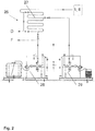
- Fig. 2 shows an arrangement upstream of the flotation device 1.
- the flocculator 26 advantageously has a curved and winding long line 27, into which coagulant can be introduced by a coagulant metering device 28.
- flocculant is introduced into the water to be cleaned by a flocculant metering device 29 before it flows to the inlet distributor 8 of the flotation device 1 according to FIG Fig. 1 , 3rd or 4th flows.
- a coagulant chemically breaks bonds, causing particles to agglomerate in a water to be cleaned.
- flocculants or flocculants are fed into the long line 27, whereby physical agglomeration or a precipitation of particles is promoted.
- the water treated in this way is then fed into the flotation device 1 described here Fig. 1 , 3rd and 4th introduced, which is designed as HPDF (High Performance Decompression Flotation) flotation device.
- HPDF High Performance Decompression Flotation
Landscapes
- Life Sciences & Earth Sciences (AREA)
- Engineering & Computer Science (AREA)
- Chemical & Material Sciences (AREA)
- Biotechnology (AREA)
- Chemical Kinetics & Catalysis (AREA)
- Hydrology & Water Resources (AREA)
- Environmental & Geological Engineering (AREA)
- Water Supply & Treatment (AREA)
- Organic Chemistry (AREA)
- Physical Water Treatments (AREA)
Abstract
Description
- Die Erfindung betrifft eine Flotationsvorrichtung nach dem Oberbegriff des Patentanspruchs 1.
- Aus dem Stand der Technik ist es bekannt, Gase durch Wasser zu waschen bzw. nass-elektrostatisch abzuscheiden, nämlich von Partikeln zu befreien. Wasser bzw. eine Waschlösung, welches bzw. welche die Partikel aufgenommen hat, muss gereinigt werden, um wieder einem Prozess zur Verfügung stehen zu können. Vor diesem Hintergrund ist insbesondere bekannt, Zentrifugen zu verwenden, welche Schwebstoffe und Partikel aus dem Wasser abscheiden.
- Eine dichte Phase oder eine eingedickte Phase, wird üblicherweise zur Zentrifuge geführt. Obwohl eine Zentrifuge sich mit bis zu 3.800 Umdrehungen pro Minute drehen kann, ist die Qualität der Reinigung nicht besonders gut, da nur größere Partikel abgeschieden werden und das Wasser einen hohen Feinstoffanteil behält.
- Es verbleiben ca. 40 bis 50 % der Partikel im gereinigten Wasser. Bei der Verwendung einer Zentrifuge ist insbesondere nachteilig, dass diese sehr verschleißanfällig ist und einen hohen Instandhaltungsbedarf aufweist. Hiermit gehen hohe Kosten einher. Weiter ist nachteilig, dass eine Anlage, auch eine Produktionsanlage, dann längere Zeit ruht, wenn eine Zentrifuge gewartet werden muss und Instandsetzungsarbeiten erforderlich werden. Des Weiteren verursachen Zentrifugen bzw. Dekanter einen hohen elektrischen Energieaufwand.
- Vor diesem Hintergrund ist aus der
DE 20 2015 102 572 U1 bekannt geworden zur Reinigung von Wasser eine Flotationsvorrichtung zu verwenden, die Mikroblasen aus Luft erzeugt. Die Mikroblasen nehmen Partikel im Wasser an dessen Oberfläche mit. An der Oberfläche entsteht so ein schwimmfähiges Flotat, nämlich ein Feststoff-Luft-Flocken-Gemisch. - Die Mikroblasen entstehen, wenn in Wasser gelöste Luft aufgrund einer Druckabsenkung aus dem Wasser entweicht. In einem Sättiger wird Luft zunächst in Wasser gelöst, indem innerhalb des Sättigers ein Druck herrscht, der weit über dem Atmosphärendruck liegt. Sobald das unter Druck stehende Wasser-Luft-Gemisch über Ventile in das Flotationsbecken eingeleitet wird, entweicht die Luft in Form von Mikroblasen, da das Wasser-Luft-Gemisch nicht mehr unter Druck steht.
- Die Verwendung von Ventilen, insbesondere einer Vielzahl von Ventilen, ist jedoch apparativ aufwendig, da diese geeignet angesteuert und ebenfalls gewartet werden müssen. Auch hiermit gehen Kosten einher. Des Weiteren stellen Ventile potentielle Schwachstellen dar, an denen es zu Leckagen kommen kann. Des Weiteren sind Ventile verschleißanfällig.
- Der Erfindung liegt daher die Aufgabe zugrunde, eine Flotationsvorrichtung anzugeben, in deren Flotationsbecken ein unter Druck stehendes Flüssigkeits-Luft-Gemisch möglichst zuverlässig und möglichst homogen einbringbar ist.
- Die vorliegende Erfindung löst diese Aufgabe mit den Merkmalen des Patentanspruchs 1.
- Erfindungsgemäß ist erkannt worden, dass mindestens ein Einspeiser mit einem Strömungskanal, der längs seiner Erstreckung unterschiedliche Strömungsquerschnittsflächen aufweist, die Verwendung eines Ventils, welches selbständig pneumatisch, elektrisch oder elektropneumatisch einen Strömungskanal mechanisch absperrt, öffnet oder regelt, überflüssig macht. Der Druck innerhalb der Leitung, die vom Sättiger wegführt, kann bei geeigneter Wahl der Strömungsquerschnittsflächen im Wesentlichen erhalten oder sogar konstant bleiben.
- Es findet gerade kein wesentlicher Druckverlust statt, wenn das unter Druck stehende Flüssigkeits-Gas-Gemisch in die sich bereits im Flotationsbecken befindliche Flüssigkeit einströmt. Es sind keine Ventile notwendig, welche die Flüssigkeit im Inneren des Flotationsbeckens vom unter Druck stehenden Flüssigkeits-Gas-Gemisch mechanisch abtrennen.
- Sobald das unter Druck stehende Flüssigkeits-Gas-Gemisch in das Flotationsbecken einströmt, findet dort eine Entspannung statt, so dass Mikroblasen des ausgasenden Gases ein Flotat an der Oberfläche des Flotationsbeckens erzeugen.
- Der Einspeiser könnte eine Venturidüse aufweisen oder als solche ausgebildet sein. Venturidüsen sind besonders gut geeignet, um ein unter Druck stehendes Flüssigkeits-Gas-Gemisch in das Flotationsbecken zu leiten und dieses dabei geeignet zu entspannen, so dass ein Druckabfall in einer Leitung nicht zu groß wird. Der Venturieffekt wird genutzt, um auf schließende Ventile zu verzichten.
- Die Leitung, die vom Sättiger wegführt, nämlich eine Verteilleitung, könnte sich zumindest abschnittsweise um das Flotationsbecken herum erstrecken, wobei die Leitung ohne Zwischenschaltung eines Ventils in mehrere Einspeiser mündet, die voneinander beabstandet an oder in der Außen- oder Innenwand des Flotationsbeckens angeordnet sind. Hierdurch kann das Flüssigkeits-Gas-Gemisch an verschiedenen Stellen in das Flotationsbecken eingebracht werden und ein Flotat möglichst homogen im Flotationsbecken verteilt erzeugen.
- Der Einspeiser oder jeder Einspeiser könnte in eine Injektorlanze münden, welche in das Innere des Flotationsbeckens ragt, wobei dem in das Innere ragenden Ende der Injektorlanze ein konvexes Prallblech, nämlich ein Prallverteiler, zugeordnet ist. Durch Injektorlanzen kann das Flüssigkeits-Gas-Gemisch gut im Inneren und in der Tiefe des Flotationsbeckens verteilt werden. Durch die Ausbildung der Prallbleche wird das ausgasende Gas in feine Blasen verteilt, wenn das Flüssigkeits-Gas-Gemisch auf diese auftrifft. Der Einspeiser kann die Wandung des Flotationsbeckens durchgreifen und in eine Injektorlanze münden. Durch das Auftreffen auf die Prallbleche wird der im Zweistoffgemisch enthaltene Luft-Sauerstoff in kleine Blasen zerstäubt bzw. zerkleinert.
- Es könnte ein Zulaufverteiler zum Einbringen von zu reinigender Flüssigkeit in das Flotationsbecken vorgesehen sein, wobei sich der Zulaufverteiler zumindest teilweise längs einer Außen- oder Innenwand des Flotationsbeckens erstreckt und mit Schlitzen versehen ist. Durch einen Zulaufverteiler kann die zu reinigende Flüssigkeit längs einer Strecke über die gesamte Breite in das Flotationsbecken über die Schlitze eingebracht bzw. homogen verteilt eingeströmt werden.
- Die Schlitze könnten als Längsschlitze ausgebildet sein, welche derart angeordnet sind, dass die zu reinigende Flüssigkeit unter einem Winkel von 5 bis 50° gegen die Horizontale geneigt in das Flotationsbecken homogen einleitbar ist. Hierdurch erfolgt eine Durchmischung der Flüssigkeit, die sich schon im Flotationsbecken befindet. Anstelle von Schlitzen könnten auch andere Durchgänge, wie beispielsweise Löcher, ovale Öffnungen oder Öffnungen mit anderer Geometrie, vorgesehen sein.
- In einem oberen Bereich des Flotationsbeckens könnte ein Flotaträumer angeordnet sein.
- Alternativ oder zusätzlich könnte in einem unteren Bereich des Flotationsbeckens ein Sedimenträumer angeordnet sein. Durch einen Flotaträumer kann Flotat, welches sich an der Oberfläche der Flüssigkeit im Flotationsbecken angesammelt hat, abgeführt werden. Durch den Sedimenträumer kann Sediment am Boden des Flotationsbeckens abgeführt werden.
- An den Flotaträumer könnte sich eine obere geneigte Rampe mit einer Länge von bevorzugt 50 bis 80 cm anschließen, auf welche Flotat durch den Flotaträumer aufbringbar ist. Da die Rampe geneigt ist, wird Flotat auf der Rampe entwässert, bevor es zu einem Entwässerungscontainer abgeführt wird.
- Es könnte ein Überlaufwehr in Form eines ersten Beckens vorgesehen sein, in welches bereits vorgereinigte Flüssigkeit hineinströmen kann, bevor diese in ein zweites Becken hineinströmt. Durch das Überlaufwehr kann der Pegel der Flüssigkeit im Flotationsbecken gut eingeregelt werden, so dass der Flotaträumer das Flotat gut ergreifen und abführen kann. Durch die Justierung des Überlaufwehrs kann ein Trockensubstanzgehalt entsprechenden Anforderungen angepasst werden.
- Die hier beschriebene Flotationsvorrichtung kann bevorzugt in der Holz verarbeitenden Industrie, in Energieerzeugungsanlagen, in der Glas- oder Mineralwolleindustrie oder in der Industrie allgemein verwendet werden.
- Bei der Verwendung der beschriebenen Flotationsvorrichtung ist von besonderem Vorteil, dass am Boden angereichertes Sediment und an der Flüssigkeitsoberfläche sich befindendes Flotat in den gleichen Entwässerungscontainer fallen und einen bereits relativ hohen Trockengehalt aufweisen.
- In der Zeichnung zeigen
- Fig. 1
- oben eine teilweise geschnittene und schematische Darstellung einer Flotationsvorrichtung, bei welcher Venturidüsen verwendet werden, um ein Flüssigkeits-Gas-Gemisch in das Flotationsbecken einzubringen, und unten eine geschnittene Ansicht eines Entwässerungscontainers, der Flotat aus der Flotationsvorrichtung aufnimmt,
- Fig. 2
- oben in schematischer Darstellung einen Flockulator, in den Flüssigkeit aus einem Dickstofftank eingeleitet wird, unten links eine Koagulationsmitteldosiereinrichtung und unten rechts eine Flockungsmitteldosiereinrichtung,
- Fig. 3
- oben eine perspektivische Ansicht der Flotationsvorrichtung und unten eine Seitenansicht der Flotationsvorrichtung gemäß
Fig. 1 , und - Fig. 4
- oben eine weitere Seitenansicht der Flotationsvorrichtung gemäß
Fig. 1 , unten links eine Ansicht auf den Zulaufverteiler und unten links eine Ansicht auf das Überlaufwehr. -
Fig. 1 zeigt eine Flotationsvorrichtung 1, umfassend ein Flotationsbecken 2 zum Aufnehmen von zu reinigender Flüssigkeit und einen Sättiger 3, zum Aufnehmen eines unter Druck stehenden Flüssigkeits-Gas-Gemischs, wobei vom Sättiger 3 eine Leitung 4, nämlich eine Verteilleitung, zu mindestens einem Einspeiser 5 führt, durch welchen das unter Druck stehende Flüssigkeits-Gas-Gemisch in das Flotationsbecken 2 einleitbar ist. - Der Einspeiser 5 weist bzw. alle Einspeiser 5 weisen einen Strömungskanal 30 auf, der längs seiner Erstreckung unterschiedliche Strömungsquerschnittsflächen 31, 32 aufweist.
- Der Einspeiser 5 weist bzw. jeder Einspeiser 5 weisen je eine Venturidüse auf oder ist bzw. sind als solche ausgebildet. Dies ist unten links in
Fig. 1 schematisch dargestellt. -
Fig. 3 zeigt besonders anschaulich, dass sich die Leitung 4 zumindest abschnittsweise um das Flotationsbecken 2 herum erstreckt, wobei die Leitung 4 ohne Zwischenschaltung eines Ventils in mehrere Einspeiser 5 mündet, die voneinander beabstandet an oder in der Außenwand des Flotationsbeckens 2 angeordnet sind. -
Fig. 1 zeigt insbesondere in der mittleren gestrichelt dargestellten Detailansicht, dass der Einspeiser 5 in eine Injektorlanze 6 mündet, welche in das Innere des Flotationsbeckens 2 ragt, wobei dem in das Innere ragenden Ende der Injektorlanze 6 ein konvexes Prallblech 7, nämlich ein Prallverteiler, zugeordnet ist. Die konvexe Seite des Prallblechs 7 ist dem Ende der Injektorlanze 6 zugewandt. - Mehrere Injektorlanzen 6 sind mit den Einspeisern 5 mittels Venturidüsen verbunden. Es ist ganz konkret kein Ventil vorgesehen, welches die Verbindung zwischen der Leitung 4 und dem Inneren des Flotationsbeckens 2 begrenzt. Der Fachmann würde erwarten, dass eine Zuleitung der unter Druck stehenden Flüssigkeit aus der Leitung 4 in das Flotationsbecken 2 zu einem sofortigen Druckabfall führen würde. Hierdurch würde die in das Flotationsbecken 2 einströmende Flüssigkeit fast nicht mehr unter Druck stehen, so dass ein effektives Ausgasen von Luft-Sauerstoff nicht möglich wäre.
- Durch das Vorsehen der Venturidüsen wird der Druck in der Leitung 4 im Wesentlichen konstant aufrechterhalten, so dass die unter Druck stehende Flüssigkeit ringsum in das Flotationsbecken 2 unter Druck stehend eingeleitet werden kann.
- Durch die unter Druck stehende Flüssigkeit, welche sich innerhalb des Flotationsbeckens 2 entspannt, wird ein Mikroblaseneffekt bewirkt, welcher Partikel an die Oberfläche der Flüssigkeit im Flotationsbecken 2 mitnimmt. An der Oberfläche der Flüssigkeit bildet sich ein Schaum, nämlich das Flotat 16, in dem Partikel angereichert sind. Der Sättiger 3 ist als Druckbehälter ausgestaltet, der im konkret dargestellten Beispiel an der Außenseite des Flotationsbeckens 2 angeordnet ist.
-
Fig. 1 zeigt weiter, dass ein Zulaufverteiler 8 zum Einbringen von zu reinigender Flüssigkeit in das Flotationsbecken 2 vorgesehen ist, wobei sich der Zulaufverteiler 8 zumindest teilweise längs einer Außenwand des Flotationsbeckens 2 erstreckt und mit Schlitzen 9 versehen ist. Der Zulaufverteiler 8 ist in die Außenwand integriert. Dies ist insbesondere inFig. 3 dargestellt. -
Fig. 1 zeigt, dass innerhalb des Zulaufverteilers 8 eine Verteilerstruktur 8a vorgesehen ist, um in der Zeichenebene von links einströmende Flüssigkeit über die Länge des Zulaufverteilers 8 zu verteilen. Die Schlitze 9 sind als Längsschlitze ausgebildet, welche derart angeordnet sind, dass die zu reinigende Flüssigkeit unter einem Winkel von 5 bis 50° gegen die Horizontale geneigt in das Flotationsbecken 2 einspritzbar oder einleitbar ist. Durch das homogene Einleiten der zu reinigenden Flüssigkeit wird die bereits im Behälter befindliche Flüssigkeit durchmischt. - In einem oberen Bereich des Flotationsbeckens 2 ist ein Flotaträumer 10 angeordnet. In einem unteren Bereich des Flotationsbeckens 2 ist ein Sedimenträumer 11 angeordnet.
- Der Flotaträumer 10 ist eine Art oberes Förderband. Der Flotaträumer 10 weist Schaber auf, welche über die Flüssigkeitsoberfläche streichen und das Flotat 16 einer geneigten oberen Rampe 12 zuführen. Die obere Rampe 12 ist derart lang ausgebildet, dass Flotat 16, welches sich auf der Rampe 12 befindet, entwässert werden kann. An den Flotaträumer 10 schließt sich die obere geneigte Rampe 12 mit einer Länge von 50 bis 80 cm an, auf welche das Flotat 16 durch den Flotaträumer 10 aufbringbar ist.
- Es ist auch ein Überlaufwehr 13 in Form eines ersten Beckens vorgesehen, in welches bereits vorgereinigte Flüssigkeit, ein sogenanntes Permeat oder eine Klarphase, hineinströmen kann, bevor diese in ein zweites Becken 14 hineinströmt.
-
Fig. 1 zeigt weiter, dass oberhalb der oberen Rampe 12 eine Rinne 15 vorgesehen ist, welche als Sedimentverteiler dient. Die Rinne 15 weist Schlitze oder Löcher auf, damit Wasser aus dem Sediment in das Flotationsbecken 2 zurückströmen kann. - Mit Bezug zu
Fig. 1 erfolgt ein Reinigungsverfahren bevorzugt wie folgt:
Rohwasser oder Schmutzwasser strömt in der Zeichenebene von links in den Zulaufverteiler 8 und wird von dort in das Flotationsbecken 2 unter einem Winkel eingeströmt. - Aus den Injektionslanzen 6 tritt ein Zweistoffgemisch aus, mikrofeine Gasblasen entstehen und nehmen Partikel mit an die Oberfläche der Flüssigkeit im Flotationsbecken 2.
- Dort reichert sich ein Flotat 16 an, welches vom Flotaträumer 10 auf die Rampe 12 und von dort in einen Schlammaustragungsschacht 17 verbracht wird. Von der oberen Rampe 12 läuft zuvor Flüssigkeit zurück in das Flotationsbecken 2.
- Das von Flüssigkeit befreite Flotat 16 wird in den Schlammaustragungsschacht 17 gefördert. Die Förderung geschieht durch die Schaber des Flotaträumers 10. Vom Schlammaustragungsschacht 17 wird das Flotat 16 in einen Entwässerungscontainer 25 geführt.
- Am Boden des Behälters befindet sich der Sedimenträumer 11, nämlich eine Art unteres Förderband. Der Sedimenträumer 11 räumt Sediment vom Boden des Flotationsbeckens 2 ab und führt dieses auf eine ebenfalls geneigte untere Rampe 11a. Von der unteren Rampe 11a fällt das Sediment in einen Sedimentaustragungsschacht 18.
- Von dort wird das Sediment durch einen Schneckenförderer 19 zu einer Sedimentpumpe 20 verbracht, welche das Sediment über eine Sedimentleitung 21 in die Rinne 15 fördert. Dort wird das Sediment wie zuvor beschrieben über Schlitze in der Rinne 15 entwässert.
- Die Flüssigkeit rinnt durch die Schlitze in der Rinne 15 auf die obere Rampe 12 und läuft von dort zurück in das Flotationsbecken 2. Von der Rinne 15, welche konkret mit Längsschlitzen versehen ist, fällt das Sediment sodann ebenfalls in den Schlammaustragungsschacht 17 und wird zum Entwässerungscontainer 25 abgeführt.
- Aus dem Flotationsbecken 2 strömt eine wässrige Klarphase, das sogenannte Permeat über einen Klarphasenauslauf 22 in das Überlaufwehr 13. Von dort kann das Permeat in das zweite Becken 14 überlaufen. Vom zweiten Becken 14 kann die Klarphase zu einer anderen Anlage geführt werden.
- Aus dem Überlaufwehr 13 aber wird ein Teil des Permeats über eine Permeatpumpe 23 zum Sättiger 3 verbracht, wo das Permeat mit Druckuft unter 6 bar beaufschlagt wird.
- Die Druckluft wird über eine Druckluftleitung 24 von oben in den Sättiger 3 eingebracht. Am unteren Ende des schräg stehenden Sättigers 3 wird das unter Druck stehende Permeat, wie zuvor beschrieben, in die Leitung 4 und von dort zu den Einspeisern 5 verbracht.
-
Fig. 2 zeigt eine Anordnung, die der Flotationsvorrichtung 1 vorgelagert ist. - Von einem nicht gezeigten Dickstofftank strömt zu reinigendes Wasser in einen Flockulator 26. Vorteilhafter Weise weist der Flockulator 26 eine geschwungene und gewundene Langleitung 27 auf, in welche Koagulationsmittel von einer Koagulationsmitteldosiereinrichtung 28 eingebracht werden kann.
- Des Weiteren wird Flockungsmittel von einer Flockungsmitteldosiereinrichtung 29 in das zu reinigende Wasser eingebracht, bevor es zu dem Zulaufverteiler 8 der Flotationsvorrichtung 1 gemäß
Fig. 1 ,3 oder4 strömt. - Ein Koagulationsmittel spaltet Bindungen chemisch auf, so dass es zu Agglomerationen von Partikeln in einem zu reinigenden Wasser kommt.
- Des Weiteren werden Flockungsmittel oder Flockulationsmittel in die Langleitung 27 eingespeist, wodurch eine physikalische Agglomeration oder ein Ausfallen von Partikeln begünstigt wird.
- Das so aufbereitete Wasser wird dann in die hier beschriebene Flotationsvorrichtung 1 gemäß
Fig. 1 ,3 und4 eingebracht, welche als HPDF (High Performance Decompression Flotation)-Flotationsvorrichtung ausgestaltet ist. -
- 1
- Flotationsvorrichtung
- 2
- Flotationsbecken von 1
- 3
- Sättiger von 1
- 4
- Leitung
- 5
- Einspeiser
- 6
- Injektorlanze
- 7
- Prallblech oder Prallverteiler von 6
- 8
- Zulaufverteiler
- 8a
- Verteilerstruktur von 8
- 9
- Schlitze von 8
- 10
- Flotaträumer
- 11
- Sedimenträumer
- 12
- obere Rampe
- 13
- Überlaufwehr, erstes Becken
- 14
- zweites Becken
- 15
- Rinne
- 16
- Flotat
- 17
- Schlammaustragungsschacht
- 18
- Sedimentaustragungsschacht
- 19
- Schneckenförderer
- 20
- Sedimentpumpe
- 21
- Sedimentleitung zu 15
- 22
- Klarphasenauslauf
- 23
- Permeatpumpe zu 3
- 24
- Druckluftleitung zu 3
- 25
- Entwässerungscontainer
- 26
- Flockulator
- 27
- Langleitung von 26
- 28
- Koagulationsmitteldosiereinrichtung
- 29
- Flockungsmitteldosiereinrichtung
- 30
- Strömungskanal von 5
- 31, 32
- Strömungsquerschnittsfläche von 30
Claims (10)
- Flotationsvorrichtung (1), umfassend ein Flotationsbecken (2) zum Aufnehmen von zu reinigender Flüssigkeit und einen Sättiger (3) zum Aufnehmen eines unter Druck stehenden Flüssigkeits-Gas-Gemischs, wobei vom Sättiger (3) eine Leitung (4) zu mindestens einem Einspeiser (5) führt, durch welchen das unter Druck stehende Flüssigkeits-Gas-Gemisch in das Flotationsbecken (2) einleitbar ist,
dadurch gekennzeichnet, dass
der Einspeiser (5) einen Strömungskanal (30) aufweist, der längs seiner Erstreckung unterschiedliche Strömungsquerschnittsflächen (31, 32) aufweist. - Flotationsvorrichtung nach Anspruch 1, dadurch gekennzeichnet, dass der Einspeiser (5) eine Venturidüse aufweist oder als solche ausgebildet ist.
- Flotationsvorrichtung nach Anspruch 1 oder 2, dadurch gekennzeichnet, dass sich die Leitung (4) zumindest abschnittsweise um das Flotationsbecken (2) herum erstreckt, wobei die Leitung (4) ohne Zwischenschaltung eines Ventils in mehrere Einspeiser (5) mündet, die voneinander beabstandet an oder in der Außen- oder Innenwand des Flotationsbeckens (2) angeordnet sind.
- Flotationsvorrichtung nach einem der voranstehenden Ansprüche,
dadurch gekennzeichnet, dass der Einspeiser (5) in eine Injektorlanze (6) mündet, welche in das Innere des Flotationsbeckens (2) ragt, wobei dem in das Innere ragenden Ende der Injektorlanze (6) ein konvexes Prallblech (7), nämlich ein Prallverteiler, zugeordnet ist. - Flotationsvorrichtung nach einem der voranstehenden Ansprüche,
dadurch gekennzeichnet, dass ein Zulaufverteiler (8) zum Einbringen von zu reinigender Flüssigkeit in das Flotationsbecken (2) vorgesehen ist, wobei sich der Zulaufverteiler (8) zumindest teilweise längs einer Außen- oder Innenwand des Flotationsbeckens (2) erstreckt und mit Schlitzen (9) versehen ist. - Flotationsvorrichtung nach Anspruch 5, dadurch gekennzeichnet, dass die Schlitze (9) als Längsschlitze ausgebildet sind, welche derart angeordnet sind, dass die zu reinigende Flüssigkeit unter einem Winkel von 5 bis 50° gegen die Horizontale geneigt in das Flotationsbecken (2) homogen einleitbar ist.
- Flotationsvorrichtung nach einem der voranstehenden Ansprüche,
dadurch gekennzeichnet, dass in einem oberen Bereich des Flotationsbeckens (2) ein Flotaträumer (10) angeordnet ist und/ oder dass in einem unteren Bereich des Flotationsbeckens (2) ein Sedimenträumer (11) angeordnet ist. - Flotationsvorrichtung nach Anspruch 7, dadurch gekennzeichnet, dass sich an den Flotaträumer (10) eine obere geneigte Rampe (12) anschließt, auf welche Flotat (16) durch den Flotaträumer (10) aufbringbar ist.
- Flotationsvorrichtung nach einem der voranstehenden Ansprüche,
dadurch gekennzeichnet, dass ein Überlaufwehr (13) als erstes Becken vorgesehen ist, in welches bereits vorgereinigte Flüssigkeit hineinströmen kann, bevor diese in ein zweites Becken (14) hineinströmt. - Verwendung einer Flotationsvorrichtung (1) nach einem der voranstehenden Ansprüche in der Holz verarbeitenden Industrie, in Energieerzeugungsanlagen, in der Glas- oder Mineralwolleindustrie oder In der Industrie allgemein.
Applications Claiming Priority (1)
| Application Number | Priority Date | Filing Date | Title |
|---|---|---|---|
| DE102018128951.0A DE102018128951A1 (de) | 2018-11-19 | 2018-11-19 | Flotationsvorrichtung |
Publications (2)
| Publication Number | Publication Date |
|---|---|
| EP3659710A1 true EP3659710A1 (de) | 2020-06-03 |
| EP3659710B1 EP3659710B1 (de) | 2024-08-14 |
Family
ID=68461708
Family Applications (1)
| Application Number | Title | Priority Date | Filing Date |
|---|---|---|---|
| EP19204082.2A Active EP3659710B1 (de) | 2018-11-19 | 2019-10-18 | Flotationsvorrichtung |
Country Status (5)
| Country | Link |
|---|---|
| US (1) | US11925884B2 (de) |
| EP (1) | EP3659710B1 (de) |
| CN (1) | CN111195564A (de) |
| BR (1) | BR102019019636A2 (de) |
| DE (1) | DE102018128951A1 (de) |
Families Citing this family (3)
| Publication number | Priority date | Publication date | Assignee | Title |
|---|---|---|---|---|
| DE102020104155A1 (de) | 2020-02-18 | 2021-08-19 | Ewk Umwelttechnik Gmbh | Anlage zur Wärmeauskopplung und/ oder zur Prozessflüssigkeitsaufbereitung |
| CH719588A2 (de) * | 2022-04-12 | 2023-10-31 | NewRoad AG | Vorrichtung zum Abtrennen von einem, auf einer Flüssigkeitsoberfläche einer Flüssigkeit aufschwimmendem Schaum. |
| CN115634779A (zh) * | 2022-10-25 | 2023-01-24 | 赤峰山金红岭有色矿业有限责任公司 | 一种浮选机新型全截面刮泡装置 |
Citations (7)
| Publication number | Priority date | Publication date | Assignee | Title |
|---|---|---|---|---|
| US2242139A (en) * | 1938-03-25 | 1941-05-13 | Walter C Munroe | Method and apparatus for water purification |
| US3542675A (en) * | 1968-07-26 | 1970-11-24 | Combustion Eng | Water treatment |
| US3679056A (en) * | 1970-08-13 | 1972-07-25 | Envirotech Corp | Flotation apparatus |
| GB2024192A (en) * | 1978-06-30 | 1980-01-09 | Pielkenrood Vinitex Bv | Flotation process |
| US4935154A (en) * | 1984-04-18 | 1990-06-19 | Arnold Kenneth E | Water treating using a series coalescing flume |
| US20040031742A1 (en) * | 2001-06-12 | 2004-02-19 | Hydrotreat, Inc. | Methods and apparatus for oil demulsification and separation of oil and suspended solids from produced water |
| DE202015102572U1 (de) | 2015-05-19 | 2015-06-15 | Envirochemie Gmbh | Druckentspannungsflotation zur Behandlung von Absorbaten aus Nass-Elektrofiltern zur Abluftreinigung |
Family Cites Families (11)
| Publication number | Priority date | Publication date | Assignee | Title |
|---|---|---|---|---|
| US3371779A (en) * | 1965-06-24 | 1968-03-05 | Borden Co | Concentration of minerals |
| US4681682A (en) * | 1983-07-26 | 1987-07-21 | Alar Engineering Corporation | Air flotation clarifier |
| US5240600A (en) * | 1990-07-03 | 1993-08-31 | International Environmental Systems, Inc., Usa | Water and wastewater treatment system |
| DE4407064C1 (de) * | 1994-03-03 | 1995-08-10 | Lucas Dipl Ing Menke | Vorrichtung zur Gasblasenflotation |
| SE503894C2 (sv) * | 1995-01-19 | 1996-09-30 | Norrtaelje Kommun | Anordning för distribution och dispersion av luftmättat vatten |
| SE9504386L (sv) * | 1995-12-07 | 1997-06-08 | Purac Ab | Flotationsapparat och förfarande |
| US6074557A (en) * | 1998-02-02 | 2000-06-13 | Lyles, Sr.; Robert G. | Water treatment device and method |
| GB0610384D0 (en) * | 2006-05-25 | 2006-07-05 | Boc Group Plc | Treatment of aqueous liquid |
| KR101164660B1 (ko) * | 2012-03-13 | 2012-07-12 | (주) 우경엔지니어링 | 저수지 및 연못 수질정화를 위한 용존공기부상 처리시스템 |
| KR101886649B1 (ko) * | 2016-08-10 | 2018-08-10 | 주식회사 에네트 | 초미세기포를 이용한 이동식 녹조제거선 |
| EP3616795A1 (de) * | 2018-08-29 | 2020-03-04 | Sulzer Management AG | Öltröpfchenflotationseinheit mit wehren und hydraulischen mitteln |
-
2018
- 2018-11-19 DE DE102018128951.0A patent/DE102018128951A1/de not_active Withdrawn
-
2019
- 2019-09-20 BR BR102019019636-0A patent/BR102019019636A2/pt not_active Application Discontinuation
- 2019-10-18 EP EP19204082.2A patent/EP3659710B1/de active Active
- 2019-10-28 US US16/666,258 patent/US11925884B2/en active Active
- 2019-11-19 CN CN201911134137.5A patent/CN111195564A/zh active Pending
Patent Citations (7)
| Publication number | Priority date | Publication date | Assignee | Title |
|---|---|---|---|---|
| US2242139A (en) * | 1938-03-25 | 1941-05-13 | Walter C Munroe | Method and apparatus for water purification |
| US3542675A (en) * | 1968-07-26 | 1970-11-24 | Combustion Eng | Water treatment |
| US3679056A (en) * | 1970-08-13 | 1972-07-25 | Envirotech Corp | Flotation apparatus |
| GB2024192A (en) * | 1978-06-30 | 1980-01-09 | Pielkenrood Vinitex Bv | Flotation process |
| US4935154A (en) * | 1984-04-18 | 1990-06-19 | Arnold Kenneth E | Water treating using a series coalescing flume |
| US20040031742A1 (en) * | 2001-06-12 | 2004-02-19 | Hydrotreat, Inc. | Methods and apparatus for oil demulsification and separation of oil and suspended solids from produced water |
| DE202015102572U1 (de) | 2015-05-19 | 2015-06-15 | Envirochemie Gmbh | Druckentspannungsflotation zur Behandlung von Absorbaten aus Nass-Elektrofiltern zur Abluftreinigung |
Also Published As
| Publication number | Publication date |
|---|---|
| BR102019019636A2 (pt) | 2020-06-02 |
| EP3659710B1 (de) | 2024-08-14 |
| DE102018128951A1 (de) | 2020-05-20 |
| US20200155971A1 (en) | 2020-05-21 |
| CN111195564A (zh) | 2020-05-26 |
| US11925884B2 (en) | 2024-03-12 |
Similar Documents
| Publication | Publication Date | Title |
|---|---|---|
| EP3659710B1 (de) | Flotationsvorrichtung | |
| EP0652039B1 (de) | Waschturm für eine Rauchgasentschwefelungsanlage | |
| DE2526912A1 (de) | Vorrichtung zur reinigung eines gasstroms | |
| DE4116916C2 (de) | Flotationseinrichtung zur Störstoff- insbesondere Druckfarbenentfernung aus Altpapiersuspensionen | |
| DE2161198C3 (de) | Vorrichtung zur Reinigung der Abluft einer Spritzkabine | |
| EP2463058B1 (de) | Strahldüse für eine Vorrichtung zum Strahlbearbeiten bzw. Strahlen von Gegenständen | |
| EP1854524B1 (de) | Abwasserreinigungsanlage mit verbesserter Belebtschlammabscheidung | |
| DE4407343C2 (de) | Vorrichtung zum Abscheiden von Partikeln mit fester Konsistenz aus einer Flüssigkeit | |
| DE2417580A1 (de) | Verfahren und vorrichtung zum richten eines feste abriebpartikel enhaltenden fluessigkeitsstrahls auf die oberflaeche eines werkstuecks | |
| DE19752470C2 (de) | Verfahren und Anlage zum Abtennen von SO¶2¶ aus Abgas | |
| EP1028192A1 (de) | Verfahren zur Entfernung von Feststoffen aus einer wässrigen Papierfasersuspension | |
| DE102006058626B3 (de) | Anlage zum Beleimen von Fasern für die Herstellung von Faserplatten, insbesondere MDF-Platten oder dergleichen Holzwerkstoffplatten | |
| EP2170606A2 (de) | Filtration für druckmaschinen | |
| DE102010060135A1 (de) | Strahldüse für eine Vorrichtung zum Strahlbearbeiten von Gegenständen | |
| DE3715263A1 (de) | Verfahren und vorrichtung zur reinigung von abluft | |
| AT14542U1 (de) | Schaumrückführung | |
| DE102015212798B4 (de) | Vorrichtung und Verfahren zum Benetzen von Partikeln | |
| DE8702677U1 (de) | Vorrichtung zum Aufbereiten eines Lackschlamm-Wassergemisches | |
| EP1806181A1 (de) | Verfahren und Vorrichtung zur Aufbereitung von Kies, Sand oder dergleichen | |
| DE102008062198A1 (de) | Flotation | |
| DE1196136B (de) | Vorrichtung zum Belueften von Wasser | |
| EP1039054B1 (de) | Verfahren und Vorrichtung zur Reinhaltung eines Beckens | |
| DE4215397A1 (de) | Vorrichtung zum Austragen von Lackpartikeln aus Umwälzwasser von Lackspritzkabinen | |
| DE202004000569U1 (de) | Spritzvorrichtung für Klärwerksbecken | |
| DE29701738U1 (de) | Vorrichtung zum Austragen von Lackschlamm |
Legal Events
| Date | Code | Title | Description |
|---|---|---|---|
| PUAI | Public reference made under article 153(3) epc to a published international application that has entered the european phase |
Free format text: ORIGINAL CODE: 0009012 |
|
| STAA | Information on the status of an ep patent application or granted ep patent |
Free format text: STATUS: THE APPLICATION HAS BEEN PUBLISHED |
|
| AK | Designated contracting states |
Kind code of ref document: A1 Designated state(s): AL AT BE BG CH CY CZ DE DK EE ES FI FR GB GR HR HU IE IS IT LI LT LU LV MC MK MT NL NO PL PT RO RS SE SI SK SM TR |
|
| AX | Request for extension of the european patent |
Extension state: BA ME |
|
| STAA | Information on the status of an ep patent application or granted ep patent |
Free format text: STATUS: REQUEST FOR EXAMINATION WAS MADE |
|
| 17P | Request for examination filed |
Effective date: 20201014 |
|
| RBV | Designated contracting states (corrected) |
Designated state(s): AL AT BE BG CH CY CZ DE DK EE ES FI FR GB GR HR HU IE IS IT LI LT LU LV MC MK MT NL NO PL PT RO RS SE SI SK SM TR |
|
| STAA | Information on the status of an ep patent application or granted ep patent |
Free format text: STATUS: EXAMINATION IS IN PROGRESS |
|
| 17Q | First examination report despatched |
Effective date: 20220209 |
|
| RAP1 | Party data changed (applicant data changed or rights of an application transferred) |
Owner name: VALMET TECHNOLOGIES OY |
|
| GRAP | Despatch of communication of intention to grant a patent |
Free format text: ORIGINAL CODE: EPIDOSNIGR1 |
|
| STAA | Information on the status of an ep patent application or granted ep patent |
Free format text: STATUS: GRANT OF PATENT IS INTENDED |
|
| INTG | Intention to grant announced |
Effective date: 20240529 |
|
| GRAS | Grant fee paid |
Free format text: ORIGINAL CODE: EPIDOSNIGR3 |
|
| GRAA | (expected) grant |
Free format text: ORIGINAL CODE: 0009210 |
|
| STAA | Information on the status of an ep patent application or granted ep patent |
Free format text: STATUS: THE PATENT HAS BEEN GRANTED |
|
| AK | Designated contracting states |
Kind code of ref document: B1 Designated state(s): AL AT BE BG CH CY CZ DE DK EE ES FI FR GB GR HR HU IE IS IT LI LT LU LV MC MK MT NL NO PL PT RO RS SE SI SK SM TR |
|
| REG | Reference to a national code |
Ref country code: GB Ref legal event code: FG4D Free format text: NOT ENGLISH |
|
| REG | Reference to a national code |
Ref country code: CH Ref legal event code: EP |
|
| REG | Reference to a national code |
Ref country code: DE Ref legal event code: R096 Ref document number: 502019011877 Country of ref document: DE |
|
| REG | Reference to a national code |
Ref country code: IE Ref legal event code: FG4D Free format text: LANGUAGE OF EP DOCUMENT: GERMAN |
|
| REG | Reference to a national code |
Ref country code: LT Ref legal event code: MG9D |
|
| REG | Reference to a national code |
Ref country code: NL Ref legal event code: MP Effective date: 20240814 |
|
| PG25 | Lapsed in a contracting state [announced via postgrant information from national office to epo] |
Ref country code: NO Free format text: LAPSE BECAUSE OF FAILURE TO SUBMIT A TRANSLATION OF THE DESCRIPTION OR TO PAY THE FEE WITHIN THE PRESCRIBED TIME-LIMIT Effective date: 20241114 |
|
| PG25 | Lapsed in a contracting state [announced via postgrant information from national office to epo] |
Ref country code: PT Free format text: LAPSE BECAUSE OF FAILURE TO SUBMIT A TRANSLATION OF THE DESCRIPTION OR TO PAY THE FEE WITHIN THE PRESCRIBED TIME-LIMIT Effective date: 20241216 Ref country code: NL Free format text: LAPSE BECAUSE OF FAILURE TO SUBMIT A TRANSLATION OF THE DESCRIPTION OR TO PAY THE FEE WITHIN THE PRESCRIBED TIME-LIMIT Effective date: 20240814 Ref country code: PL Free format text: LAPSE BECAUSE OF FAILURE TO SUBMIT A TRANSLATION OF THE DESCRIPTION OR TO PAY THE FEE WITHIN THE PRESCRIBED TIME-LIMIT Effective date: 20240814 Ref country code: FI Free format text: LAPSE BECAUSE OF FAILURE TO SUBMIT A TRANSLATION OF THE DESCRIPTION OR TO PAY THE FEE WITHIN THE PRESCRIBED TIME-LIMIT Effective date: 20240814 Ref country code: GR Free format text: LAPSE BECAUSE OF FAILURE TO SUBMIT A TRANSLATION OF THE DESCRIPTION OR TO PAY THE FEE WITHIN THE PRESCRIBED TIME-LIMIT Effective date: 20241115 |
|
| PG25 | Lapsed in a contracting state [announced via postgrant information from national office to epo] |
Ref country code: BG Free format text: LAPSE BECAUSE OF FAILURE TO SUBMIT A TRANSLATION OF THE DESCRIPTION OR TO PAY THE FEE WITHIN THE PRESCRIBED TIME-LIMIT Effective date: 20240814 |
|
| PG25 | Lapsed in a contracting state [announced via postgrant information from national office to epo] |
Ref country code: LV Free format text: LAPSE BECAUSE OF FAILURE TO SUBMIT A TRANSLATION OF THE DESCRIPTION OR TO PAY THE FEE WITHIN THE PRESCRIBED TIME-LIMIT Effective date: 20240814 |
|
| PG25 | Lapsed in a contracting state [announced via postgrant information from national office to epo] |
Ref country code: IS Free format text: LAPSE BECAUSE OF FAILURE TO SUBMIT A TRANSLATION OF THE DESCRIPTION OR TO PAY THE FEE WITHIN THE PRESCRIBED TIME-LIMIT Effective date: 20241214 |
|
| PG25 | Lapsed in a contracting state [announced via postgrant information from national office to epo] |
Ref country code: HR Free format text: LAPSE BECAUSE OF FAILURE TO SUBMIT A TRANSLATION OF THE DESCRIPTION OR TO PAY THE FEE WITHIN THE PRESCRIBED TIME-LIMIT Effective date: 20240814 |
|
| PG25 | Lapsed in a contracting state [announced via postgrant information from national office to epo] |
Ref country code: ES Free format text: LAPSE BECAUSE OF FAILURE TO SUBMIT A TRANSLATION OF THE DESCRIPTION OR TO PAY THE FEE WITHIN THE PRESCRIBED TIME-LIMIT Effective date: 20240814 Ref country code: RS Free format text: LAPSE BECAUSE OF FAILURE TO SUBMIT A TRANSLATION OF THE DESCRIPTION OR TO PAY THE FEE WITHIN THE PRESCRIBED TIME-LIMIT Effective date: 20241114 |
|
| PG25 | Lapsed in a contracting state [announced via postgrant information from national office to epo] |
Ref country code: RS Free format text: LAPSE BECAUSE OF FAILURE TO SUBMIT A TRANSLATION OF THE DESCRIPTION OR TO PAY THE FEE WITHIN THE PRESCRIBED TIME-LIMIT Effective date: 20241114 Ref country code: PT Free format text: LAPSE BECAUSE OF FAILURE TO SUBMIT A TRANSLATION OF THE DESCRIPTION OR TO PAY THE FEE WITHIN THE PRESCRIBED TIME-LIMIT Effective date: 20241216 Ref country code: PL Free format text: LAPSE BECAUSE OF FAILURE TO SUBMIT A TRANSLATION OF THE DESCRIPTION OR TO PAY THE FEE WITHIN THE PRESCRIBED TIME-LIMIT Effective date: 20240814 Ref country code: NO Free format text: LAPSE BECAUSE OF FAILURE TO SUBMIT A TRANSLATION OF THE DESCRIPTION OR TO PAY THE FEE WITHIN THE PRESCRIBED TIME-LIMIT Effective date: 20241114 Ref country code: NL Free format text: LAPSE BECAUSE OF FAILURE TO SUBMIT A TRANSLATION OF THE DESCRIPTION OR TO PAY THE FEE WITHIN THE PRESCRIBED TIME-LIMIT Effective date: 20240814 Ref country code: LV Free format text: LAPSE BECAUSE OF FAILURE TO SUBMIT A TRANSLATION OF THE DESCRIPTION OR TO PAY THE FEE WITHIN THE PRESCRIBED TIME-LIMIT Effective date: 20240814 Ref country code: IS Free format text: LAPSE BECAUSE OF FAILURE TO SUBMIT A TRANSLATION OF THE DESCRIPTION OR TO PAY THE FEE WITHIN THE PRESCRIBED TIME-LIMIT Effective date: 20241214 Ref country code: HR Free format text: LAPSE BECAUSE OF FAILURE TO SUBMIT A TRANSLATION OF THE DESCRIPTION OR TO PAY THE FEE WITHIN THE PRESCRIBED TIME-LIMIT Effective date: 20240814 Ref country code: GR Free format text: LAPSE BECAUSE OF FAILURE TO SUBMIT A TRANSLATION OF THE DESCRIPTION OR TO PAY THE FEE WITHIN THE PRESCRIBED TIME-LIMIT Effective date: 20241115 Ref country code: FI Free format text: LAPSE BECAUSE OF FAILURE TO SUBMIT A TRANSLATION OF THE DESCRIPTION OR TO PAY THE FEE WITHIN THE PRESCRIBED TIME-LIMIT Effective date: 20240814 Ref country code: ES Free format text: LAPSE BECAUSE OF FAILURE TO SUBMIT A TRANSLATION OF THE DESCRIPTION OR TO PAY THE FEE WITHIN THE PRESCRIBED TIME-LIMIT Effective date: 20240814 Ref country code: BG Free format text: LAPSE BECAUSE OF FAILURE TO SUBMIT A TRANSLATION OF THE DESCRIPTION OR TO PAY THE FEE WITHIN THE PRESCRIBED TIME-LIMIT Effective date: 20240814 |
|
| PG25 | Lapsed in a contracting state [announced via postgrant information from national office to epo] |
Ref country code: RO Free format text: LAPSE BECAUSE OF FAILURE TO SUBMIT A TRANSLATION OF THE DESCRIPTION OR TO PAY THE FEE WITHIN THE PRESCRIBED TIME-LIMIT Effective date: 20240814 Ref country code: DK Free format text: LAPSE BECAUSE OF FAILURE TO SUBMIT A TRANSLATION OF THE DESCRIPTION OR TO PAY THE FEE WITHIN THE PRESCRIBED TIME-LIMIT Effective date: 20240814 Ref country code: SM Free format text: LAPSE BECAUSE OF FAILURE TO SUBMIT A TRANSLATION OF THE DESCRIPTION OR TO PAY THE FEE WITHIN THE PRESCRIBED TIME-LIMIT Effective date: 20240814 |
|
| PG25 | Lapsed in a contracting state [announced via postgrant information from national office to epo] |
Ref country code: EE Free format text: LAPSE BECAUSE OF FAILURE TO SUBMIT A TRANSLATION OF THE DESCRIPTION OR TO PAY THE FEE WITHIN THE PRESCRIBED TIME-LIMIT Effective date: 20240814 |
|
| PG25 | Lapsed in a contracting state [announced via postgrant information from national office to epo] |
Ref country code: CZ Free format text: LAPSE BECAUSE OF FAILURE TO SUBMIT A TRANSLATION OF THE DESCRIPTION OR TO PAY THE FEE WITHIN THE PRESCRIBED TIME-LIMIT Effective date: 20240814 |
|
| PG25 | Lapsed in a contracting state [announced via postgrant information from national office to epo] |
Ref country code: SK Free format text: LAPSE BECAUSE OF FAILURE TO SUBMIT A TRANSLATION OF THE DESCRIPTION OR TO PAY THE FEE WITHIN THE PRESCRIBED TIME-LIMIT Effective date: 20240814 |
|
| REG | Reference to a national code |
Ref country code: DE Ref legal event code: R097 Ref document number: 502019011877 Country of ref document: DE |
|
| REG | Reference to a national code |
Ref country code: CH Ref legal event code: PL |
|
| PLBE | No opposition filed within time limit |
Free format text: ORIGINAL CODE: 0009261 |
|
| STAA | Information on the status of an ep patent application or granted ep patent |
Free format text: STATUS: NO OPPOSITION FILED WITHIN TIME LIMIT |
|
| PG25 | Lapsed in a contracting state [announced via postgrant information from national office to epo] |
Ref country code: MC Free format text: LAPSE BECAUSE OF FAILURE TO SUBMIT A TRANSLATION OF THE DESCRIPTION OR TO PAY THE FEE WITHIN THE PRESCRIBED TIME-LIMIT Effective date: 20240814 |
|
| PG25 | Lapsed in a contracting state [announced via postgrant information from national office to epo] |
Ref country code: LU Free format text: LAPSE BECAUSE OF NON-PAYMENT OF DUE FEES Effective date: 20241018 Ref country code: BE Free format text: LAPSE BECAUSE OF NON-PAYMENT OF DUE FEES Effective date: 20241031 |
|
| PG25 | Lapsed in a contracting state [announced via postgrant information from national office to epo] |
Ref country code: FR Free format text: LAPSE BECAUSE OF NON-PAYMENT OF DUE FEES Effective date: 20241031 |
|
| 26N | No opposition filed |
Effective date: 20250515 |
|
| GBPC | Gb: european patent ceased through non-payment of renewal fee |
Effective date: 20241114 |
|
| PG25 | Lapsed in a contracting state [announced via postgrant information from national office to epo] |
Ref country code: CH Free format text: LAPSE BECAUSE OF NON-PAYMENT OF DUE FEES Effective date: 20241031 |
|
| REG | Reference to a national code |
Ref country code: BE Ref legal event code: MM Effective date: 20241031 |
|
| PG25 | Lapsed in a contracting state [announced via postgrant information from national office to epo] |
Ref country code: SE Free format text: LAPSE BECAUSE OF FAILURE TO SUBMIT A TRANSLATION OF THE DESCRIPTION OR TO PAY THE FEE WITHIN THE PRESCRIBED TIME-LIMIT Effective date: 20240814 |
|
| PG25 | Lapsed in a contracting state [announced via postgrant information from national office to epo] |
Ref country code: GB Free format text: LAPSE BECAUSE OF NON-PAYMENT OF DUE FEES Effective date: 20241114 |
|
| PG25 | Lapsed in a contracting state [announced via postgrant information from national office to epo] |
Ref country code: IE Free format text: LAPSE BECAUSE OF NON-PAYMENT OF DUE FEES Effective date: 20241018 |
|
| PGFP | Annual fee paid to national office [announced via postgrant information from national office to epo] |
Ref country code: DE Payment date: 20251021 Year of fee payment: 7 |
|
| PGFP | Annual fee paid to national office [announced via postgrant information from national office to epo] |
Ref country code: AT Payment date: 20251022 Year of fee payment: 7 |
|
| PGFP | Annual fee paid to national office [announced via postgrant information from national office to epo] |
Ref country code: IT Payment date: 20251024 Year of fee payment: 7 |
|
| PG25 | Lapsed in a contracting state [announced via postgrant information from national office to epo] |
Ref country code: CY Free format text: LAPSE BECAUSE OF FAILURE TO SUBMIT A TRANSLATION OF THE DESCRIPTION OR TO PAY THE FEE WITHIN THE PRESCRIBED TIME-LIMIT; INVALID AB INITIO Effective date: 20191018 |
|
| PG25 | Lapsed in a contracting state [announced via postgrant information from national office to epo] |
Ref country code: HU Free format text: LAPSE BECAUSE OF FAILURE TO SUBMIT A TRANSLATION OF THE DESCRIPTION OR TO PAY THE FEE WITHIN THE PRESCRIBED TIME-LIMIT; INVALID AB INITIO Effective date: 20191018 |