EP3659415A1 - Fahrzeug mit kratzbodenkettenspanner - Google Patents
Fahrzeug mit kratzbodenkettenspanner Download PDFInfo
- Publication number
- EP3659415A1 EP3659415A1 EP19207698.2A EP19207698A EP3659415A1 EP 3659415 A1 EP3659415 A1 EP 3659415A1 EP 19207698 A EP19207698 A EP 19207698A EP 3659415 A1 EP3659415 A1 EP 3659415A1
- Authority
- EP
- European Patent Office
- Prior art keywords
- chain
- hydraulic
- vehicle
- hydraulic cylinders
- operating mode
- Prior art date
- Legal status (The legal status is an assumption and is not a legal conclusion. Google has not performed a legal analysis and makes no representation as to the accuracy of the status listed.)
- Granted
Links
- 238000000034 method Methods 0.000 claims abstract description 23
- 210000003608 fece Anatomy 0.000 claims abstract description 11
- 239000010871 livestock manure Substances 0.000 claims abstract description 11
- 238000006073 displacement reaction Methods 0.000 claims abstract description 6
- 239000000463 material Substances 0.000 claims description 21
- 230000033001 locomotion Effects 0.000 claims description 10
- 230000004913 activation Effects 0.000 claims description 7
- 238000010586 diagram Methods 0.000 description 12
- 239000003921 oil Substances 0.000 description 8
- 230000005540 biological transmission Effects 0.000 description 5
- 238000010276 construction Methods 0.000 description 2
- 239000010720 hydraulic oil Substances 0.000 description 2
- 241000221535 Pucciniales Species 0.000 description 1
- 239000002361 compost Substances 0.000 description 1
- 238000005260 corrosion Methods 0.000 description 1
- 230000007797 corrosion Effects 0.000 description 1
- 230000000694 effects Effects 0.000 description 1
- 239000011499 joint compound Substances 0.000 description 1
- 238000012423 maintenance Methods 0.000 description 1
- 230000008439 repair process Effects 0.000 description 1
Images


Classifications
-
- A—HUMAN NECESSITIES
- A01—AGRICULTURE; FORESTRY; ANIMAL HUSBANDRY; HUNTING; TRAPPING; FISHING
- A01C—PLANTING; SOWING; FERTILISING
- A01C3/00—Treating manure; Manuring
- A01C3/06—Manure distributors, e.g. dung distributors
-
- B—PERFORMING OPERATIONS; TRANSPORTING
- B60—VEHICLES IN GENERAL
- B60P—VEHICLES ADAPTED FOR LOAD TRANSPORTATION OR TO TRANSPORT, TO CARRY, OR TO COMPRISE SPECIAL LOADS OR OBJECTS
- B60P1/00—Vehicles predominantly for transporting loads and modified to facilitate loading, consolidating the load, or unloading
- B60P1/36—Vehicles predominantly for transporting loads and modified to facilitate loading, consolidating the load, or unloading using endless chains or belts thereon
- B60P1/38—Vehicles predominantly for transporting loads and modified to facilitate loading, consolidating the load, or unloading using endless chains or belts thereon forming the main load-transporting element or part thereof
-
- B—PERFORMING OPERATIONS; TRANSPORTING
- B65—CONVEYING; PACKING; STORING; HANDLING THIN OR FILAMENTARY MATERIAL
- B65G—TRANSPORT OR STORAGE DEVICES, e.g. CONVEYORS FOR LOADING OR TIPPING, SHOP CONVEYOR SYSTEMS OR PNEUMATIC TUBE CONVEYORS
- B65G23/00—Driving gear for endless conveyors; Belt- or chain-tensioning arrangements
- B65G23/44—Belt or chain tensioning arrangements
Definitions
- the present invention concerns a vehicle, preferably an agricultural vehicle, such as a spreader for delivering spreadable materials, such as manure, comprising a truck box and a hydraulic system, comprising
- the present invention concerns a method for the hydraulic tensioning of a chain tensioning device in a vehicle, preferably an agricultural vehicle, such as a spreader for delivering spreadable materials, such as manure, comprising a truck box and a hydraulic system, comprising
- the bottom chains are typically arranged along the long sides of the vehicle and are thus under great load, in that the entire contents rest above on the transverse carrier elements between the bottom chains.
- This adjustment device works in that the idler wheel is mounted in a longitudinal glide block in a line motion.
- the glide block is provided with a threaded rod with an adjustment nut, which works against a fixed buffer, wherein the position of the idler wheel in relation to the other idler wheel(s) in the chain transmission can be adjusted using the nut.
- This is a relative simple and robust construction, which also makes it easy to both tighten and disassemble a bottom chain. The bottom chains can thus be manually tightened by tightening the nut in the adjustment device.
- a tightening of the bottom chains at regular intervals is therefore desirable because it avoids considerable unnecessary wear. Furthermore, a worn and slack bottom chain has a negative impact on the chain transmission's effectiveness. If the bottom chain is too slack, there is also a high risk of the land wheel slipping with stoppage as a result. A slack bottom chain is also difficult to control correctly and there is therefore a high risk of the chain becoming caught and hence damaged. Agricultural vehicles, such as the above-mentioned spreaders, generally operate in highly corrosive environments and often handle very aggressive materials, which means that the bottom chains are also exposed to corrosion, which also contributes to wear and reduced durability of the chains.
- the bottom chains in connection with agricultural vehicles are mounted however in the bottom of the truck box, wherein they can be difficult to access, which can make it difficult to carry out this tightening. If there are long periods between adjustments, it is also probable that the adjustment nut rusts over, which also makes it difficult to tension the chain.
- the vehicles are used intensely for short periods, after which they are stored away until the next season. This means that in practice the chains are only rarely tensioned or even not at all. What typically happens is that the bottom chain is taken off and one or more chain links removed when it becomes unacceptably slack.
- the vehicle has however different operating modes. For example a mode for spreading the contents in the truck out onto the ground and a mode for reversing the contents in the truck.
- the load on the bottom chain can vary between these two operating modes.
- the known vehicles therefore have disadvantages in that they do not adjust the tensioning force of the chain tensioner to the operating mode.
- the bottom chain can be driven in an overtensioned state.
- the purpose of the invention is to provide a vehicle which obviates these disadvantages.
- the purpose of the invention is to provide a vehicle with a self-adjusting bottom chain tensioning system in a vehicle of the type mentioned in the introduction, wherein the bottom chain is tensioned with a different tensioning force in the different operating modes.
- the purpose of the invention is to provide a vehicle in which wear to the bottom chain is minimised.
- the purpose of the invention is to provide a vehicle in which wear to the hydraulic cylinders is minimised.
- the purpose of the invention is to specify a method for the hydraulic tensioning of a chain tensioning device in a vehicle, which reduces wear to the hydraulic cylinders and/or bottom chain.
- the load on the chain tensioning device will be moderate.
- the material is pulled directly towards the hydraulic motor.
- the load of the chain itself has en effect on the chain tensioning device.
- the different effective piston areas are a simple way of producing different tensioning forces in the chain tensioning device in the first and second operating mode.
- the adjusted and different tensioning forces in the first and second operating mode reduce wear to the bottom chain and hydraulic cylinders in relation to use of the same tensioning force in the first and second operating mode.
- a pressure regulation can be used for both chain drive and the chain tensioning device. This achieves a robust system requiring minimal service.
- Activation of the first and second effective piston area in the different operating modes is provided by changing the direction of flow in the hydraulic system.
- a change in the direction of flow can be provided by using a diversion valve.
- the pump in the hydraulic system can be mounted on the vehicle itself.
- the pump can be driven, for example, by a drive shaft, which is connected to a tractor.
- the hydraulic system comprises means for connection to the hydraulic pump.
- This will be means in the form of a hydraulic cable on the outlet side and a hydraulic cable on the return side.
- an oil reservoir will also be provided, to which the return oil is fed and from which the hydraulic oil is supplied to the suction side of the hydraulic pump.
- the hydraulic pump and oil reservoir will generally be placed on a tractor that pulls the vehicle but can alternatively be mounted on the vehicle and driven by a PTO shaft or an off-road heavy goods vehicle.
- the tensioning force can be, for example, between 30 and 200 bar, preferably between 50 and 180 bar, more preferably 135 bar.
- the vehicle can be a manure spreader.
- the vehicle is characterised in that the hydraulic cylinders are double-acting cylinders.
- the double-acting cylinders make it possible for the chain tensioning device to be provided on the vehicle in a space-saving manner.
- the chain tensioning device can be used in vehicles with compact construction.
- the double-acting cylinders can be double-acting cylinders with two chambers. One of the chambers can be driven as a single-acting cylinder.
- the vehicle is characterised in that the first and second effective piston area is provided by activation of a different number of single-acting cylinders.
- the vehicle is characterised in that the hydraulic cylinders are mounted in parallel.
- the vehicle is characterised in that a diversion valve is mounted between the hydraulic cylinders and the hydraulic pump, which reverses the direction of flow in the hydraulic system.
- the diversion valve provides activation of the first and second effective piston area by reversing the direction of flow in the hydraulic system. At the same time, the direction of operation is controlled by the bottom chain with the diversion valve. Thus, it is always ensured that the chain tensioning pressure is adjusted to the direction of operation of the bottom chain and therefore the operating mode of the vehicle.
- the vehicle is characterised in that a changeover valve is mounted between the selector valve and overpressure valve.
- the changeover valve comprises two inputs and one output.
- the changeover valve's inputs are connected to the selector valve, and the changeover valve's output is connected to the overpressure valve.
- the changeover valve works together with the diversion valve and provides activation of the first and second effective piston area.
- the vehicle is characterised in that a return valve and an overpressure valve are mounted between the hydraulic cylinders and the hydraulic pump in parallel between at least some of the hydraulic cylinders and hydraulic pump.
- a return valve and an overpressure valve maintain a minimum pressure in the chain tensioning device. Thus, a minimum pressure will always be maintained between the applicable hydraulic cylinders and hydraulic pump.
- the pressure in the vehicle's hydraulic system can briefly rise.
- the tensioning force in the chain tensioning device will be increased.
- the vehicle comprises only one return valve, the chain tensioning device will subsequently be maintained at too high a pressure.
- the overpressure valve ensures that the pressure in the hydraulic cylinders can fall again.
- the overpressure valve obviates overten-sioning of the chain tensioning device which can occur during pressure peaks at the start of reversing.
- wear to the bottom chain and hydraulic cylinders is reduced.
- a further aspect of the invention is a method for the hydraulic tensioning of the chain tensioning device in a vehicle, preferably an agricultural vehicle, such as a spreader for delivering spreadable materials, such as manure, comprising a truck box and a hydraulic system, comprising
- the method can be used with either embodiment of the vehicle described in the present application.
- the method is characterised in that the further aspect comprises the following steps wherein:
- the reversing of the direction of flow can produce activation of the first and/or the second effective piston area.
- the reversing of the direction of flow can provide a change in the direction of operation of the bottom chain.
- the reversing of the direction of flow can be provided with a diversion valve.
- the method is characterised in that the first and second effective piston area is provided using one or more double-acting hydraulic cylinders.
- the double-acting hydraulic cylinders are space-saving.
- the method can be used in vehicles where there are space restrictions for the hydraulic cylinders and/or chain tensioning device.
- the method is characterised in that the further aspect comprises the following steps wherein:
- Maintaining the minimum pressure in the chain tensioning device excludes the possibility of driving the bottom chain at too low a chain tensioning pressure, should the pressure in the hydraulic system fall below the minimum pressure when in operation. Thus, wear to the bottom chain is reduced.
- the minimum pressure can be provided with the return valve and overpressure valve, which are connected in parallel, between the pump and at least some of the hydraulic cylinders.
- Fig. 1 shows a vehicle 24 provided by the invention in the form of a spreader for delivering spreadable materials, such as manure and suchlike, wherein the bottom chains 1 are arranged next to each other in the bottom of the truck box and are provided with transverse carrier elements 9.
- the bottom chains 1 are also provided with a chain tensioning device 2 for tensioning the bottom chains 1.
- the bottom chains 1 are driven by a hydraulic motor 5, which is connected to a sprocket (not shown), which the bottom chains 1 in the end of the propulsion device is engaged with, which sprocket is housed in the bottom of the truck box or in the vehicle's chassis 7.
- a sprocket not shown
- each of the bottom chains 1 are engaged around an idler wheel 3, which is mounted on the chain tensioning device 2, which is again attached to the truck box or in the vehicle's chassis 7.
- the bottom chain 1 has a first direction of operation 21 and a second direction of operation 22.
- the first direction of operation 21 is used for unloading / spreading the material on the truck.
- the second direction of operation 22 is used for reversing the material on the truck.
- the chain tensioning device 2 which is shown in more detail in fig. 1a , can displace the idler wheel 3 in a link motion 6 in a direction parallel to the bottom chain's direction of propulsion.
- the chain tensioning device 2 comprises a number of hydraulic cylinders 4, which with the cylinder housing is attached to chassis 7 or the bottom plate in the truck box.
- the hydraulic cylinders 4 are arranged in a cylinder control 8, which shows individual routes for the hydraulic cylinders' pistons, such that the cylinders 4 will push the control 8 away from the mounting in the chassis/bottom plate 7, wherein the idler wheels 3, which are arranged on the cylinder control 8, are thus displaced linearly in their line motion 6.
- FIG. 2 and 3 show a diagram of an embodiment provided by the invention of a hydraulic system 11, which is built into a vehicle according to figure 1 .
- the outlet side of the hydraulic system 11 is marked with a thicker line.
- a hydraulic pump 12 drives one or more hydraulic motors 5 and hydraulic cylinders 4 in the chain tensioning device 2.
- the hydraulic system 11 is connected to the hydraulic pump 12 via a hydraulic cable 25 on the outlet side and a hydraulic cable 26 on the return side.
- a hydraulic cable 25 on the outlet side and a hydraulic cable 26 on the return side.
- an oil reservoir 27 will also be provided, to which the return oil is fed and from which the hydraulic oil is supplied to the suction side of the hydraulic pump 12.
- the hydraulic pump and oil reservoir will generally be placed on a tractor that pulls the vehicle but can alternatively be mounted on the vehicle 24 and driven by a PTO shaft 28 (see Fig. 1 ).
- the hydraulic cylinders 4 are double-acting cylinders 13.
- the hydraulic cylinders 4 are mounted in parallel.
- a diversion valve 14 is mounted between the hydraulic cylinders 4 and the hydraulic pump 12.
- the diversion valve 14 can reverse the direction of flow 15 in the hydraulic system 11.
- a return valve 16 and an overpressure valve 17 are mounted in parallel between the hydraulic cylinders 4 and the hydraulic pump 12. In other words, the valves 16, 17 are mounted between the hydraulic pump 12 and one side of the double-acting cylinders 13.
- a changeover valve 20 is mounted between the selector valve 14 and the overpressure valve 17.
- the changeover valve 20 comprises two inputs and one output.
- the changeover valve's inputs are connected to the selector valve 14, and the changeover valve's output is connected to the overpressure valve 17.
- the diversion valve is in a position wherein the direction of flow 15 is not reversed. Therefore, the vehicle is in a first operating mode wherein the bottom chain (not shown) is in a first direction of operation. For example for spreading material on the truck.
- Figure 2a shows in schematic form the first effective piston area 18, which is the total hatched area for the four hydraulic cylinders in the system.
- the diversion valve is in a position wherein the direction of flow 15 is reversed. Therefore, the vehicle is in a second operating mode wherein the bottom chain (not shown) is in a second direction of operation. For example for reversing material on the truck.
- Figure 3a shows in schematic form the second effective piston area 19, which is the total hatched area for the four hydraulic cylinders 4 in the system.
- the method for the hydraulic tensioning of a chain tensioning device in the vehicle 24 comprises the following steps, wherein:
- the method can be used with either embodiment of the vehicle described in the present application.
- the method can further comprise that:
- Figure 3 shows a reversed direction of flow in relation to figure 2.
- Figure 2 shows the system in a first operating mode, wherein the first effective piston area is activated and figure 3 shows a second operating mode, wherein the second effective piston area is activated.
- the reversing of the direction of flow provides a change in the direction of operation of the bottom chain.
- the reversing of the direction of flow is provided with a diversion valve (14).
- the method is characterised in that the first and second effective piston area is provided using one or more double-acting hydraulic cylinders.
- the double-acting hydraulic cylinders are space-saving.
- the method can be used in vehicles where there are space restrictions for the hydraulic cylinders and/or chain tensioning device.
- the method is characterised in that the further aspect comprises the following steps wherein:
- Maintaining the minimum pressure in the chain tensioning device excludes the possibility of driving the bottom chain at too low a chain tensioning pressure, should the pressure in the hydraulic system fall below the minimum pressure when in operation. Thus, wear to the bottom chain is reduced.
- the minimum pressure can be provided with the return valve and overpressure valve, which are connected in parallel, between the pump and at least some of the hydraulic cylinders.
- Fig. 4 and 5 show a diagram of a further embodiment provided by the invention of a hydraulic system 11, which is built into a vehicle according to figure 1 .
- the outlet side of the hydraulic system 11 is marked with a thicker line.
- a hydraulic pump 12 drives one or more hydraulic motors 5 and hydraulic cylinders 4 in the chain tensioning device 2.
- the hydraulic cylinders 4 are mounted in parallel.
- the hydraulic cylinders 4 are double-acting cylinders 13 with two chambers. One chamber is driven double-acting and one chamber is driven single-acting.
- a diversion valve 14 is mounted between the hydraulic cylinders 4 and the hydraulic pump 12.
- the diversion valve 14 can reverse the direction of flow 15 in the hydraulic system 11.
- a return valve 16 and an overpressure valve 17 are mounted in parallel between the hydraulic cylinders 4 and the hydraulic pump 12.
- the valves 16, 17 are mounted between the hydraulic pump 12 and one side of the first chamber of the double-acting cylinders 13.
- a changeover valve 20 is mounted between the selector valve 14 and the overpressure valve 17.
- the changeover valve 20 comprises two inputs and one output.
- the changeover valve's inputs are connected to the selector valve 14, and the changeover valve's output is connected to the overpressure valve 17.
- the diversion valve is in a position wherein the direction of flow 15 is not reversed. Therefore, the vehicle is in a first operating mode wherein the bottom chain (not shown) is in a first direction of operation. For example for spreading material on the truck.
- Figure 4a shows in schematic form the first effective piston area 18, which is the total hatched area for the four hydraulic cylinders in the system.
- the diversion valve is in a position wherein the direction of flow 15 is reversed. Therefore, the vehicle is in a second operating mode wherein the bottom chain (not shown) is in a second direction of operation. For example for reversing material on the truck.
- Figure 5a shows in schematic form the second effective piston area 19, which is the total hatched area for the four hydraulic cylinders 4 in the system.
- Fig. 6 and 7 show a diagram of a further embodiment provided by the invention of a hydraulic system 11, which is built into a vehicle according to figure 1 .
- the outlet side of the hydraulic system 11 is marked with a thicker line.
- a hydraulic pump 12 drives one or more hydraulic motors 5 and hydraulic cylinders 4 in the chain tensioning device 2.
- the hydraulic cylinders 4 are mounted in parallel.
- the hydraulic cylinders 4 are single-acting cylinders 23.
- a diversion valve 14 is mounted between the hydraulic cylinders 4 and the hydraulic pump 12.
- the diversion valve 14 can reverse the direction of flow 15 in the hydraulic system 11.
- a return valve 16 and an overpressure valve 17 are mounted in parallel between some of the hydraulic cylinders 4 and the hydraulic pump 12.
- a changeover valve 20 is mounted between the selector valve 14 and the overpressure valve 17.
- the changeover valve 20 comprises two inputs and one output.
- the changeover valve's inputs are connected to the selector valve 14, and the changeover valve's output is connected to the overpressure valve 17.
- the diversion valve is in a position wherein the direction of flow 15 is not reversed. Therefore, the vehicle is in a first operating mode wherein the bottom chain (not shown) is in a first direction of operation. For example for spreading material on the truck.
- Figure 6a shows in schematic form the first effective piston area 18, which is the total hatched area for the four hydraulic cylinders 4 in the system, which is pressurised.
- the diversion valve is in a position wherein the direction of flow 15 is reversed. Therefore, the vehicle is in a second operating mode wherein the bottom chain (not shown) is in a second direction of operation. For example for reversing material on the truck.
- Figure 7a shows in schematic form the second effective piston area 19, which is the total hatched area for the 8 pressurised hydraulic cylinders 4 in the system.
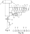
- Fig. 8 and 9 show a diagram of a further embodiment provided by the invention of a hydraulic system 11, which is built into a vehicle according to figure 1 .
- the outlet side of the hydraulic system 11 is marked with a thicker line.
- a hydraulic pump 12 drives one or more hydraulic motors 5 and hydraulic cylinders 4 in the chain tensioning device 2.
- the hydraulic cylinders 4 are mounted in parallel.
- Some of the hydraulic cylinders 4 are double-acting cylinders 13.
- a diversion valve 14 is mounted between the hydraulic cylinders 4 and the hydraulic pump 12.
- the diversion valve 14 can reverse the direction of flow 15 in the hydraulic system 11.
- a return valve 16 and an overpressure valve 17 are mounted in parallel between some of the hydraulic cylinders 4 and the hydraulic pump 12.
- a changeover valve 20 is mounted between the selector valve 14 and the overpressure valve 17.
- the changeover valve 20 comprises two inputs and one output.
- the changeover valve's inputs are connected to the selector valve 14, and the changeover valve's output is connected to the overpressure valve 17.
- the diversion valve is in a position wherein the direction of flow 15 is not reversed. Therefore, the vehicle is in a first operating mode wherein the bottom chain (not shown) is in a first direction of operation. For example for spreading material on the truck.
- Figure 8a shows in schematic form the first effective piston area 18, which is the total hatched area for the four hydraulic cylinders 4 in the system, which is pressurised.
- the diversion valve is in a position wherein the direction of flow 15 is reversed. Therefore, the vehicle is in a second operating mode wherein the bottom chain (not shown) is in a second direction of operation. For example for reversing material on the truck.
- Figure 9a shows in schematic form the second effective piston area 19, which is the total hatched area for the 8 pressurised hydraulic cylinders 4 in the system.
Landscapes
- Life Sciences & Earth Sciences (AREA)
- Engineering & Computer Science (AREA)
- Soil Sciences (AREA)
- Mechanical Engineering (AREA)
- Environmental Sciences (AREA)
- Transportation (AREA)
- Devices For Conveying Motion By Means Of Endless Flexible Members (AREA)
- Fluid-Pressure Circuits (AREA)
Applications Claiming Priority (1)
| Application Number | Priority Date | Filing Date | Title |
|---|---|---|---|
| DKPA201870780A DK179870B1 (da) | 2018-11-27 | 2018-11-27 | Køretøj med bundkædestrammer |
Publications (2)
| Publication Number | Publication Date |
|---|---|
| EP3659415A1 true EP3659415A1 (de) | 2020-06-03 |
| EP3659415B1 EP3659415B1 (de) | 2020-12-23 |
Family
ID=68583058
Family Applications (1)
| Application Number | Title | Priority Date | Filing Date |
|---|---|---|---|
| EP19207698.2A Active EP3659415B1 (de) | 2018-11-27 | 2019-11-07 | Fahrzeug mit kratzbodenkettenspanner |
Country Status (3)
| Country | Link |
|---|---|
| EP (1) | EP3659415B1 (de) |
| DK (1) | DK179870B1 (de) |
| ES (1) | ES2866182T3 (de) |
Cited By (1)
| Publication number | Priority date | Publication date | Assignee | Title |
|---|---|---|---|---|
| KR102185483B1 (ko) * | 2019-12-09 | 2020-12-02 | 농업회사법인 희망농업기계 주식회사 | 견인식 퇴비살포기 체인 장력 자동조절장치 |
Citations (4)
| Publication number | Priority date | Publication date | Assignee | Title |
|---|---|---|---|---|
| AT368469B (de) * | 1980-07-08 | 1982-10-11 | Voest Alpine Ag | Einrichtung zur einstellung der bandspannung eines bandfoerderers und verfahren zum betrieb dieser einrichtung |
| DE8902422U1 (de) * | 1989-03-01 | 1989-04-27 | Ludwig Bergmann GmbH & Co KG, 2849 Goldenstedt | Spannvorrichtung für die Förderketten eines Kratzbodenförderers oder eines ähnlichen Förderers, insbesondere für die Landwirtschaft |
| DK172309B1 (da) | 1996-09-27 | 1998-03-16 | Maskinfabriken Samson Tange A | Køretøj med bundkæder og midler til stramning af disse |
| US20150024888A1 (en) * | 2013-07-18 | 2015-01-22 | Robert M. Curfman | Displacement equalizing hydraulic tensioner for multi-strand endless chain |
-
2018
- 2018-11-27 DK DKPA201870780A patent/DK179870B1/da active IP Right Grant
-
2019
- 2019-11-07 EP EP19207698.2A patent/EP3659415B1/de active Active
- 2019-11-07 ES ES19207698T patent/ES2866182T3/es active Active
Patent Citations (5)
| Publication number | Priority date | Publication date | Assignee | Title |
|---|---|---|---|---|
| AT368469B (de) * | 1980-07-08 | 1982-10-11 | Voest Alpine Ag | Einrichtung zur einstellung der bandspannung eines bandfoerderers und verfahren zum betrieb dieser einrichtung |
| DE8902422U1 (de) * | 1989-03-01 | 1989-04-27 | Ludwig Bergmann GmbH & Co KG, 2849 Goldenstedt | Spannvorrichtung für die Förderketten eines Kratzbodenförderers oder eines ähnlichen Förderers, insbesondere für die Landwirtschaft |
| DK172309B1 (da) | 1996-09-27 | 1998-03-16 | Maskinfabriken Samson Tange A | Køretøj med bundkæder og midler til stramning af disse |
| EP0832549A1 (de) * | 1996-09-27 | 1998-04-01 | Maskinfabriken Samson, Tange A/S | Fahrzeug mit Kratzbodenkette und Vorrichtung um diese zu spannen |
| US20150024888A1 (en) * | 2013-07-18 | 2015-01-22 | Robert M. Curfman | Displacement equalizing hydraulic tensioner for multi-strand endless chain |
Cited By (1)
| Publication number | Priority date | Publication date | Assignee | Title |
|---|---|---|---|---|
| KR102185483B1 (ko) * | 2019-12-09 | 2020-12-02 | 농업회사법인 희망농업기계 주식회사 | 견인식 퇴비살포기 체인 장력 자동조절장치 |
Also Published As
| Publication number | Publication date |
|---|---|
| ES2866182T3 (es) | 2021-10-19 |
| DK179870B1 (da) | 2019-08-07 |
| DK201870780A1 (da) | 2019-08-07 |
| EP3659415B1 (de) | 2020-12-23 |
Similar Documents
| Publication | Publication Date | Title |
|---|---|---|
| DE602004010189T2 (de) | Selbstspannendes befestigungssystem | |
| EP3659415B1 (de) | Fahrzeug mit kratzbodenkettenspanner | |
| CN111867924B (zh) | 履带式车辆以及用于运行履带式车辆的方法 | |
| US7934594B2 (en) | Conveyor system for vehicle | |
| CA2374504C (en) | Load carrying body | |
| US4129258A (en) | Automatic hydraulic series-parallel shift device for implement | |
| EP2688791B1 (de) | Automatisches spannsystem für spuren eines strassenfertigers | |
| GB2393696A (en) | Tensioning system for a tracked vehicle | |
| US3477766A (en) | Apparatus for tensioning a track or the like | |
| US3700288A (en) | Paving machine | |
| US20060201777A1 (en) | Trailer having an endless conveyor | |
| US5996324A (en) | Hydraulic feeder reverser | |
| WO2005068345A1 (en) | Forklift truck for mounting on the rear of a carrying vehicle with a fork side shifting attachment | |
| EP0832549B1 (de) | Fahrzeug mit Kratzbodenkette und Vorrichtung um diese zu spannen | |
| EP2028139B1 (de) | Hydraulische Spannvorrichtung für Ketten oder Riemenförderer | |
| US10207754B2 (en) | Track system for a work vehicle | |
| WO1987004987A1 (en) | Adjusting and recoil mechanism | |
| US7389641B2 (en) | System for and method of operating a pressurized air source of a vehicular agricultural applicator | |
| WO1986001492A1 (en) | A fluid-operated, low profile reciprocating conveyor | |
| DE1258284C2 (de) | Hydrostatischer Antrieb fuer gelaendegaengige Fahrzeuge | |
| CA2498432A1 (en) | Trailer having an endless conveyor | |
| KR0137004B1 (ko) | 화물 운반장치 | |
| JP2972612B2 (ja) | 往復運動型スラットコンベヤ | |
| PL65715B1 (de) | ||
| AT267583B (de) | Erdbearbeitungs- oder Lademaschine |
Legal Events
| Date | Code | Title | Description |
|---|---|---|---|
| PUAI | Public reference made under article 153(3) epc to a published international application that has entered the european phase |
Free format text: ORIGINAL CODE: 0009012 |
|
| STAA | Information on the status of an ep patent application or granted ep patent |
Free format text: STATUS: THE APPLICATION HAS BEEN PUBLISHED |
|
| AK | Designated contracting states |
Kind code of ref document: A1 Designated state(s): AL AT BE BG CH CY CZ DE DK EE ES FI FR GB GR HR HU IE IS IT LI LT LU LV MC MK MT NL NO PL PT RO RS SE SI SK SM TR |
|
| AX | Request for extension of the european patent |
Extension state: BA ME |
|
| STAA | Information on the status of an ep patent application or granted ep patent |
Free format text: STATUS: REQUEST FOR EXAMINATION WAS MADE |
|
| 17P | Request for examination filed |
Effective date: 20200722 |
|
| RBV | Designated contracting states (corrected) |
Designated state(s): AL AT BE BG CH CY CZ DE DK EE ES FI FR GB GR HR HU IE IS IT LI LT LU LV MC MK MT NL NO PL PT RO RS SE SI SK SM TR |
|
| GRAP | Despatch of communication of intention to grant a patent |
Free format text: ORIGINAL CODE: EPIDOSNIGR1 |
|
| STAA | Information on the status of an ep patent application or granted ep patent |
Free format text: STATUS: GRANT OF PATENT IS INTENDED |
|
| RIC1 | Information provided on ipc code assigned before grant |
Ipc: A01C 3/06 20060101AFI20200828BHEP Ipc: B65G 23/44 20060101ALI20200828BHEP Ipc: B60P 1/38 20060101ALI20200828BHEP |
|
| INTG | Intention to grant announced |
Effective date: 20200923 |
|
| GRAS | Grant fee paid |
Free format text: ORIGINAL CODE: EPIDOSNIGR3 |
|
| GRAA | (expected) grant |
Free format text: ORIGINAL CODE: 0009210 |
|
| STAA | Information on the status of an ep patent application or granted ep patent |
Free format text: STATUS: THE PATENT HAS BEEN GRANTED |
|
| AK | Designated contracting states |
Kind code of ref document: B1 Designated state(s): AL AT BE BG CH CY CZ DE DK EE ES FI FR GB GR HR HU IE IS IT LI LT LU LV MC MK MT NL NO PL PT RO RS SE SI SK SM TR |
|
| REG | Reference to a national code |
Ref country code: GB Ref legal event code: FG4D |
|
| REG | Reference to a national code |
Ref country code: DE Ref legal event code: R096 Ref document number: 602019001888 Country of ref document: DE |
|
| REG | Reference to a national code |
Ref country code: AT Ref legal event code: REF Ref document number: 1346794 Country of ref document: AT Kind code of ref document: T Effective date: 20210115 |
|
| REG | Reference to a national code |
Ref country code: IE Ref legal event code: FG4D |
|
| REG | Reference to a national code |
Ref country code: NL Ref legal event code: FP |
|
| REG | Reference to a national code |
Ref country code: SE Ref legal event code: TRGR |
|
| PG25 | Lapsed in a contracting state [announced via postgrant information from national office to epo] |
Ref country code: NO Free format text: LAPSE BECAUSE OF FAILURE TO SUBMIT A TRANSLATION OF THE DESCRIPTION OR TO PAY THE FEE WITHIN THE PRESCRIBED TIME-LIMIT Effective date: 20210323 Ref country code: GR Free format text: LAPSE BECAUSE OF FAILURE TO SUBMIT A TRANSLATION OF THE DESCRIPTION OR TO PAY THE FEE WITHIN THE PRESCRIBED TIME-LIMIT Effective date: 20210324 Ref country code: RS Free format text: LAPSE BECAUSE OF FAILURE TO SUBMIT A TRANSLATION OF THE DESCRIPTION OR TO PAY THE FEE WITHIN THE PRESCRIBED TIME-LIMIT Effective date: 20201223 Ref country code: FI Free format text: LAPSE BECAUSE OF FAILURE TO SUBMIT A TRANSLATION OF THE DESCRIPTION OR TO PAY THE FEE WITHIN THE PRESCRIBED TIME-LIMIT Effective date: 20201223 |
|
| REG | Reference to a national code |
Ref country code: AT Ref legal event code: MK05 Ref document number: 1346794 Country of ref document: AT Kind code of ref document: T Effective date: 20201223 |
|
| PG25 | Lapsed in a contracting state [announced via postgrant information from national office to epo] |
Ref country code: LV Free format text: LAPSE BECAUSE OF FAILURE TO SUBMIT A TRANSLATION OF THE DESCRIPTION OR TO PAY THE FEE WITHIN THE PRESCRIBED TIME-LIMIT Effective date: 20201223 Ref country code: BG Free format text: LAPSE BECAUSE OF FAILURE TO SUBMIT A TRANSLATION OF THE DESCRIPTION OR TO PAY THE FEE WITHIN THE PRESCRIBED TIME-LIMIT Effective date: 20210323 |
|
| PG25 | Lapsed in a contracting state [announced via postgrant information from national office to epo] |
Ref country code: HR Free format text: LAPSE BECAUSE OF FAILURE TO SUBMIT A TRANSLATION OF THE DESCRIPTION OR TO PAY THE FEE WITHIN THE PRESCRIBED TIME-LIMIT Effective date: 20201223 |
|
| REG | Reference to a national code |
Ref country code: LT Ref legal event code: MG9D |
|
| PG25 | Lapsed in a contracting state [announced via postgrant information from national office to epo] |
Ref country code: LT Free format text: LAPSE BECAUSE OF FAILURE TO SUBMIT A TRANSLATION OF THE DESCRIPTION OR TO PAY THE FEE WITHIN THE PRESCRIBED TIME-LIMIT Effective date: 20201223 Ref country code: PT Free format text: LAPSE BECAUSE OF FAILURE TO SUBMIT A TRANSLATION OF THE DESCRIPTION OR TO PAY THE FEE WITHIN THE PRESCRIBED TIME-LIMIT Effective date: 20210423 Ref country code: RO Free format text: LAPSE BECAUSE OF FAILURE TO SUBMIT A TRANSLATION OF THE DESCRIPTION OR TO PAY THE FEE WITHIN THE PRESCRIBED TIME-LIMIT Effective date: 20201223 Ref country code: CZ Free format text: LAPSE BECAUSE OF FAILURE TO SUBMIT A TRANSLATION OF THE DESCRIPTION OR TO PAY THE FEE WITHIN THE PRESCRIBED TIME-LIMIT Effective date: 20201223 Ref country code: EE Free format text: LAPSE BECAUSE OF FAILURE TO SUBMIT A TRANSLATION OF THE DESCRIPTION OR TO PAY THE FEE WITHIN THE PRESCRIBED TIME-LIMIT Effective date: 20201223 Ref country code: SM Free format text: LAPSE BECAUSE OF FAILURE TO SUBMIT A TRANSLATION OF THE DESCRIPTION OR TO PAY THE FEE WITHIN THE PRESCRIBED TIME-LIMIT Effective date: 20201223 Ref country code: SK Free format text: LAPSE BECAUSE OF FAILURE TO SUBMIT A TRANSLATION OF THE DESCRIPTION OR TO PAY THE FEE WITHIN THE PRESCRIBED TIME-LIMIT Effective date: 20201223 |
|
| PG25 | Lapsed in a contracting state [announced via postgrant information from national office to epo] |
Ref country code: AT Free format text: LAPSE BECAUSE OF FAILURE TO SUBMIT A TRANSLATION OF THE DESCRIPTION OR TO PAY THE FEE WITHIN THE PRESCRIBED TIME-LIMIT Effective date: 20201223 Ref country code: PL Free format text: LAPSE BECAUSE OF FAILURE TO SUBMIT A TRANSLATION OF THE DESCRIPTION OR TO PAY THE FEE WITHIN THE PRESCRIBED TIME-LIMIT Effective date: 20201223 |
|
| REG | Reference to a national code |
Ref country code: DE Ref legal event code: R097 Ref document number: 602019001888 Country of ref document: DE |
|
| PG25 | Lapsed in a contracting state [announced via postgrant information from national office to epo] |
Ref country code: IS Free format text: LAPSE BECAUSE OF FAILURE TO SUBMIT A TRANSLATION OF THE DESCRIPTION OR TO PAY THE FEE WITHIN THE PRESCRIBED TIME-LIMIT Effective date: 20210423 |
|
| REG | Reference to a national code |
Ref country code: ES Ref legal event code: FG2A Ref document number: 2866182 Country of ref document: ES Kind code of ref document: T3 Effective date: 20211019 |
|
| PG25 | Lapsed in a contracting state [announced via postgrant information from national office to epo] |
Ref country code: IT Free format text: LAPSE BECAUSE OF FAILURE TO SUBMIT A TRANSLATION OF THE DESCRIPTION OR TO PAY THE FEE WITHIN THE PRESCRIBED TIME-LIMIT Effective date: 20201223 Ref country code: AL Free format text: LAPSE BECAUSE OF FAILURE TO SUBMIT A TRANSLATION OF THE DESCRIPTION OR TO PAY THE FEE WITHIN THE PRESCRIBED TIME-LIMIT Effective date: 20201223 |
|
| PLBE | No opposition filed within time limit |
Free format text: ORIGINAL CODE: 0009261 |
|
| STAA | Information on the status of an ep patent application or granted ep patent |
Free format text: STATUS: NO OPPOSITION FILED WITHIN TIME LIMIT |
|
| PG25 | Lapsed in a contracting state [announced via postgrant information from national office to epo] |
Ref country code: DK Free format text: LAPSE BECAUSE OF FAILURE TO SUBMIT A TRANSLATION OF THE DESCRIPTION OR TO PAY THE FEE WITHIN THE PRESCRIBED TIME-LIMIT Effective date: 20201223 |
|
| 26N | No opposition filed |
Effective date: 20210924 |
|
| PG25 | Lapsed in a contracting state [announced via postgrant information from national office to epo] |
Ref country code: IS Free format text: LAPSE BECAUSE OF FAILURE TO SUBMIT A TRANSLATION OF THE DESCRIPTION OR TO PAY THE FEE WITHIN THE PRESCRIBED TIME-LIMIT Effective date: 20210423 |
|
| PG25 | Lapsed in a contracting state [announced via postgrant information from national office to epo] |
Ref country code: MC Free format text: LAPSE BECAUSE OF FAILURE TO SUBMIT A TRANSLATION OF THE DESCRIPTION OR TO PAY THE FEE WITHIN THE PRESCRIBED TIME-LIMIT Effective date: 20201223 |
|
| PG25 | Lapsed in a contracting state [announced via postgrant information from national office to epo] |
Ref country code: LU Free format text: LAPSE BECAUSE OF NON-PAYMENT OF DUE FEES Effective date: 20211107 Ref country code: BE Free format text: LAPSE BECAUSE OF NON-PAYMENT OF DUE FEES Effective date: 20211130 |
|
| REG | Reference to a national code |
Ref country code: BE Ref legal event code: MM Effective date: 20211130 |
|
| PG25 | Lapsed in a contracting state [announced via postgrant information from national office to epo] |
Ref country code: IE Free format text: LAPSE BECAUSE OF NON-PAYMENT OF DUE FEES Effective date: 20211107 |
|
| P01 | Opt-out of the competence of the unified patent court (upc) registered |
Effective date: 20230522 |
|
| PG25 | Lapsed in a contracting state [announced via postgrant information from national office to epo] |
Ref country code: CY Free format text: LAPSE BECAUSE OF FAILURE TO SUBMIT A TRANSLATION OF THE DESCRIPTION OR TO PAY THE FEE WITHIN THE PRESCRIBED TIME-LIMIT Effective date: 20201223 |
|
| REG | Reference to a national code |
Ref country code: CH Ref legal event code: PL |
|
| PG25 | Lapsed in a contracting state [announced via postgrant information from national office to epo] |
Ref country code: LI Free format text: LAPSE BECAUSE OF NON-PAYMENT OF DUE FEES Effective date: 20221130 Ref country code: HU Free format text: LAPSE BECAUSE OF FAILURE TO SUBMIT A TRANSLATION OF THE DESCRIPTION OR TO PAY THE FEE WITHIN THE PRESCRIBED TIME-LIMIT; INVALID AB INITIO Effective date: 20191107 Ref country code: CH Free format text: LAPSE BECAUSE OF NON-PAYMENT OF DUE FEES Effective date: 20221130 |
|
| PG25 | Lapsed in a contracting state [announced via postgrant information from national office to epo] |
Ref country code: SI Free format text: LAPSE BECAUSE OF FAILURE TO SUBMIT A TRANSLATION OF THE DESCRIPTION OR TO PAY THE FEE WITHIN THE PRESCRIBED TIME-LIMIT Effective date: 20201223 |
|
| PGFP | Annual fee paid to national office [announced via postgrant information from national office to epo] |
Ref country code: NL Payment date: 20231126 Year of fee payment: 5 |
|
| PGFP | Annual fee paid to national office [announced via postgrant information from national office to epo] |
Ref country code: GB Payment date: 20231127 Year of fee payment: 5 |
|
| PGFP | Annual fee paid to national office [announced via postgrant information from national office to epo] |
Ref country code: ES Payment date: 20231201 Year of fee payment: 5 |
|
| PGFP | Annual fee paid to national office [announced via postgrant information from national office to epo] |
Ref country code: SE Payment date: 20231127 Year of fee payment: 5 Ref country code: FR Payment date: 20231127 Year of fee payment: 5 Ref country code: DE Payment date: 20231129 Year of fee payment: 5 |
|
| PG25 | Lapsed in a contracting state [announced via postgrant information from national office to epo] |
Ref country code: MK Free format text: LAPSE BECAUSE OF FAILURE TO SUBMIT A TRANSLATION OF THE DESCRIPTION OR TO PAY THE FEE WITHIN THE PRESCRIBED TIME-LIMIT Effective date: 20201223 |