EP3659413B1 - Landwirtschaftliches grabentiefenerfassungsverfahren - Google Patents
Landwirtschaftliches grabentiefenerfassungsverfahren Download PDFInfo
- Publication number
- EP3659413B1 EP3659413B1 EP19215512.5A EP19215512A EP3659413B1 EP 3659413 B1 EP3659413 B1 EP 3659413B1 EP 19215512 A EP19215512 A EP 19215512A EP 3659413 B1 EP3659413 B1 EP 3659413B1
- Authority
- EP
- European Patent Office
- Prior art keywords
- depth
- trench
- gauge wheel
- measured
- row unit
- Prior art date
- Legal status (The legal status is an assumption and is not a legal conclusion. Google has not performed a legal analysis and makes no representation as to the accuracy of the status listed.)
- Active
Links
Images


Classifications
-
- A—HUMAN NECESSITIES
- A01—AGRICULTURE; FORESTRY; ANIMAL HUSBANDRY; HUNTING; TRAPPING; FISHING
- A01B—SOIL WORKING IN AGRICULTURE OR FORESTRY; PARTS, DETAILS, OR ACCESSORIES OF AGRICULTURAL MACHINES OR IMPLEMENTS, IN GENERAL
- A01B79/00—Methods for working soil
- A01B79/005—Precision agriculture
-
- A—HUMAN NECESSITIES
- A01—AGRICULTURE; FORESTRY; ANIMAL HUSBANDRY; HUNTING; TRAPPING; FISHING
- A01C—PLANTING; SOWING; FERTILISING
- A01C7/00—Sowing
- A01C7/20—Parts of seeders for conducting and depositing seed
- A01C7/201—Mounting of the seeding tools
- A01C7/203—Mounting of the seeding tools comprising depth regulation means
-
- A—HUMAN NECESSITIES
- A01—AGRICULTURE; FORESTRY; ANIMAL HUSBANDRY; HUNTING; TRAPPING; FISHING
- A01B—SOIL WORKING IN AGRICULTURE OR FORESTRY; PARTS, DETAILS, OR ACCESSORIES OF AGRICULTURAL MACHINES OR IMPLEMENTS, IN GENERAL
- A01B71/00—Construction or arrangement of setting or adjusting mechanisms, of implement or tool drive or of power take-off; Means for protecting parts against dust, or the like; Adapting machine elements to or for agricultural purposes
- A01B71/02—Setting or adjusting mechanisms
-
- A—HUMAN NECESSITIES
- A01—AGRICULTURE; FORESTRY; ANIMAL HUSBANDRY; HUNTING; TRAPPING; FISHING
- A01B—SOIL WORKING IN AGRICULTURE OR FORESTRY; PARTS, DETAILS, OR ACCESSORIES OF AGRICULTURAL MACHINES OR IMPLEMENTS, IN GENERAL
- A01B76/00—Parts, details or accessories of agricultural machines or implements, not provided for in groups A01B51/00 - A01B75/00
-
- A—HUMAN NECESSITIES
- A01—AGRICULTURE; FORESTRY; ANIMAL HUSBANDRY; HUNTING; TRAPPING; FISHING
- A01C—PLANTING; SOWING; FERTILISING
- A01C5/00—Making or covering furrows or holes for sowing, planting or manuring
- A01C5/06—Machines for making or covering drills or furrows for sowing or planting
- A01C5/062—Devices for making drills or furrows
- A01C5/064—Devices for making drills or furrows with rotating tools
-
- G—PHYSICS
- G01—MEASURING; TESTING
- G01B—MEASURING LENGTH, THICKNESS OR SIMILAR LINEAR DIMENSIONS; MEASURING ANGLES; MEASURING AREAS; MEASURING IRREGULARITIES OF SURFACES OR CONTOURS
- G01B21/00—Measuring arrangements or details thereof, where the measuring technique is not covered by the other groups of this subclass, unspecified or not relevant
- G01B21/18—Measuring arrangements or details thereof, where the measuring technique is not covered by the other groups of this subclass, unspecified or not relevant for measuring depth
-
- G—PHYSICS
- G01—MEASURING; TESTING
- G01D—MEASURING NOT SPECIALLY ADAPTED FOR A SPECIFIC VARIABLE; ARRANGEMENTS FOR MEASURING TWO OR MORE VARIABLES NOT COVERED IN A SINGLE OTHER SUBCLASS; TARIFF METERING APPARATUS; MEASURING OR TESTING NOT OTHERWISE PROVIDED FOR
- G01D5/00—Mechanical means for transferring the output of a sensing member; Means for converting the output of a sensing member to another variable where the form or nature of the sensing member does not constrain the means for converting; Transducers not specially adapted for a specific variable
- G01D5/12—Mechanical means for transferring the output of a sensing member; Means for converting the output of a sensing member to another variable where the form or nature of the sensing member does not constrain the means for converting; Transducers not specially adapted for a specific variable using electric or magnetic means
- G01D5/14—Mechanical means for transferring the output of a sensing member; Means for converting the output of a sensing member to another variable where the form or nature of the sensing member does not constrain the means for converting; Transducers not specially adapted for a specific variable using electric or magnetic means influencing the magnitude of a current or voltage
- G01D5/142—Mechanical means for transferring the output of a sensing member; Means for converting the output of a sensing member to another variable where the form or nature of the sensing member does not constrain the means for converting; Transducers not specially adapted for a specific variable using electric or magnetic means influencing the magnitude of a current or voltage using Hall-effect devices
-
- A—HUMAN NECESSITIES
- A01—AGRICULTURE; FORESTRY; ANIMAL HUSBANDRY; HUNTING; TRAPPING; FISHING
- A01B—SOIL WORKING IN AGRICULTURE OR FORESTRY; PARTS, DETAILS, OR ACCESSORIES OF AGRICULTURAL MACHINES OR IMPLEMENTS, IN GENERAL
- A01B63/00—Lifting or adjusting devices or arrangements for agricultural machines or implements
- A01B63/02—Lifting or adjusting devices or arrangements for agricultural machines or implements for implements mounted on tractors
- A01B63/10—Lifting or adjusting devices or arrangements for agricultural machines or implements for implements mounted on tractors operated by hydraulic or pneumatic means
- A01B63/111—Lifting or adjusting devices or arrangements for agricultural machines or implements for implements mounted on tractors operated by hydraulic or pneumatic means regulating working depth of implements
-
- A—HUMAN NECESSITIES
- A01—AGRICULTURE; FORESTRY; ANIMAL HUSBANDRY; HUNTING; TRAPPING; FISHING
- A01C—PLANTING; SOWING; FERTILISING
- A01C5/00—Making or covering furrows or holes for sowing, planting or manuring
- A01C5/06—Machines for making or covering drills or furrows for sowing or planting
- A01C5/066—Devices for covering drills or furrows
- A01C5/068—Furrow packing devices, e.g. press wheels
Definitions
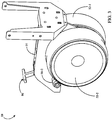
- FIG. 1 illustrates an agricultural implement, e.g., a planter, comprising a toolbar 8 to which multiple row units 10 are mounted in transversely spaced relation.
- Each row unit 10 is preferably mounted to the toolbar by a parallel arm arrangement 16 such that the row unit is permitted to translate vertically with respect to the toolbar.
- An actuator 18 is preferably pivotally mounted to the toolbar 8 and the parallel arm arrangement 16 and configured to apply supplemental downpressure to the row unit 10.
- the row unit 10 preferably includes a frame 14.
- the row unit 10 preferably includes an opening disc assembly 60 including two angled opening discs 62 rollingly mounted to a downwardly extending shank 15 of the frame 14 and disposed to open a v-shaped trench 3 in a soil surface 7 as the row unit traverses a field.
- the row unit 10 preferably includes a gauge wheel assembly 50 including two gauge wheels 52 pivotally mounted to either side of the frame 14 by two gauge wheel arms 54 and disposed to roll along the surface of the soil.
- a depth adjustment assembly 90 pivotally mounted to the frame 14 at a pivot 92 preferably contacts the gauge wheel arms 54 to limit the upward travel of the gauge wheel arms 54, thus limiting the depth of the trench opened by the opening disc assembly 60.
- a closing assembly 40 is preferably pivotally coupled to the frame 14 and configured to move soil back into the trench 3.
- seeds 5 are communicated from a hopper 12 to a seed meter 30 preferably configured to singulate the supplied seeds.
- the meter 30 is preferably a vacuum-type meter such as that disclosed in Applicant's co-pending international patent application no. PCT/US2012/030192 (Pub. No. WO/2012/129442 ).
- the seed meter 30 preferably deposits the supplied seeds into a seed tube 32.
- the seed tube 32 is preferably removably mounted to the frame 14. In operation, seeds 5 deposited by the meter 30 fall through the seed tube 32 into the trench 3.
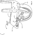
- the depth adjustment assembly 90 includes a rocker 95 pivotally mounted to a depth adjustment body 94.
- the depth adjustment body 94 is pivotally mounted to the row unit frame 14 about the pivot 92.
- a handle 98 is preferably slidably received within the depth adjustment body 94 such that the user can selectively engage and disengage the handle with one of a plurality of depth adjustment slots 97 ( FIG. 6 ) formed within the row unit frame 14.
- the upward travel of the gauge wheels 52 is limited by contact of the gauge wheel arms 54 with the rocker 95.
- the rocker 95 allows the left gauge wheel arm 54-1 to travel upward while lowering the right gauge wheel 52-2 by the same absolute displacement such that the row unit 10 rises by half the height of the obstruction.
- a depth sensor assembly 100 is shown installed on the row unit 10.
- the depth sensor assembly 100 includes a mounting bracket 110, preferably mounted between the row unit frame 14 and a closing wheel mounting block 42 to which the closing assembly 40 is pivotally mounted.
- a magnet 140 is preferably mounted to a pivot portion 56 of each gauge wheel arm 54 such that the magnet 140 travels along a circular path as the associated gauge wheel arm is rotated.
- a depth sensor 150 preferably comprising a Hall-effect sensor, is preferably supported by the bracket 110 in a position adjacent to each magnet 140 on either side of the row unit frame 14.
- the bracket 110 preferably supports the depth sensor 150 in a position that maximizes proximity to the magnet 140 without interfering with the magnet 140 when the gauge wheel 52 is raised to an extreme position.
- the bracket 110 preferably additionally supports a signal processor 120.
- both depth sensors 150-1,150-2 preferably generate a signal inversely related to the distance D1, D2 between the depth sensors 150-1,150-2 and the associated magnets 140-1,140-2, respectively.
- the magnet 140-2 rotates clockwise such that the distance D2 increases and the signal generated by the depth sensor 150-2 decreases.
- the depth sensor 150 comprises a position sensor configured to generate a signal related to the position of an object, in this case the magnet 140 and thus the gauge wheel arm to which the magnet is mounted.
- a depth sensor 150 is mounted to the pivot portion 56 of each gauge wheel arm 54 and a magnet 140 is mounted to the bracket 110.
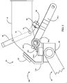
- a mounting assembly 200 is illustrated including a circumferential mounting rim 210.
- the mounting rim 210 preferably includes a flat mounting surface 214 to which the magnet 140 is mounted.
- the mounting rim 210 is preferably sized to surround a portion of the pivot portion 56 of the gauge wheel arm 54.
- the mounting rim 210 is preferably configured to receive a group of set screws 220 at radially spaced locations. In installation of the mounting rim 210, the set screws 220 are threaded into the mounting rim 210 to mount the mounting rim to the pivot portion 56.
- a cylindrical guide (not shown) is inserted in a gap between the mounting rim 210 and the pivot portion 56 while the set screws 220 are inserted in order to ensure that the mounting rim is concentrically and symmetrically positioned with respect to the pivot portion.
- the mounting rim 210 includes an opening 212 sized to receive a grease zerk 58 in the gauge wheel arm 54.
- a grease gun (not shown) is used to insert grease through the grease zerk 58 into the joint between the gauge wheel arm 54 and the row unit frame 14.
- the opening 212 is preferably sized such that the grease gun can be tightly fit inside the opening 212 between around the grease zerk 58, fixing the angular orientation of the mounting rim 210 relative to the pivot portion 56.
- the position of the opening 212 relative to the mounting surface 214 is preferably selected so that the mounting surface (as well as the magnet mounted to the mounting surface) is in a defined position with respect to the gauge wheel arm. With the magnet in the defined position, when the gauge wheel arm is at a full depth position, the magnet 140 is preferably within a reliably detectable distance of the depth sensor 150.
- a modified gauge wheel arm 54' includes a flat mounting surface 57 in the pivot portion 56.
- the magnet 140 is preferably mounted directly to the mounting surface 57.
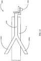
- a depth sensor 1220 is used to measure the vertical position of the row unit relative to the soil surface 7.
- the depth sensor 1220 preferably includes a pivot arm 1222 pivotally mounted to a bracket 1210.
- the bracket 1210 is preferably mounted to a lower portion of the shank 15.
- a resilient seed firmer 1214 is also mounted to the bracket 1210.
- the bracket 1210 preferably extends around the seed tube 32 as best illustrated in FIG. 12 .
- the pivot arm preferably includes left and right ground-engaging fingers 1224-1, 1224-2, respectively.
- the ground-engaging portions of the fingers 1224 are preferably spaced by a transverse spacing wider than the trench 3 such that the fingers 1224 contact the soil surface 7 on either side of the trench.
- a sensor is preferably used to generate a signal related to the angular position of the pivot arm 1222.
- the pivot arm 1222 is pivotally mounted to the bracket 1210 via a rotary encoder 1226 (e.g., an angular displacement sensor no. 55250 available from Hamlin Incorporated, Lake Mills, Wisconsin).
- the fingers 1224 ride along the soil surface 7 such that the angular position of the pivot arm is constrained by the vertical height of the row unit 10 relative to the soil surface.
- a signal generated by the encoder 1226 is thus related to the vertical height of the row unit 10 with respect to the soil, and thus to the depth of the trench 3.
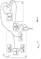
- a depth sensing system 500 for measuring row unit downforce and modifying downpressure is illustrated in FIG. 9 .
- the depth sensors 150-1,150-2 mounted to each row unit 10 are preferably in electrical communication with the processor 120.
- the processor 120 is preferably in electrical communication with a monitor 540, which is preferably mounted in a cab 80 of a tractor drawing the planter.
- the monitor 540 is preferably in electrical communication with a fluid control system 530.
- the fluid control system 530 is preferably in fluid communication with the actuator 18.
- the fluid control system 530 is preferably configured to modify the pressure applied by the actuator 18 on the row unit 10.
- the fluid control system 530 preferably includes electro-hydraulic solenoid valves in fluid communication with a down chamber and a lift chamber of the actuator 18.
- the fluid control system 530 is preferably configured to control the pressure supplied to the actuator 18 in a pressure control mode to maintain a selected pressure in the actuator, e.g., using solenoid operated pressure reducing-relieving valves.
- the monitor 540 preferably includes a central processing unit, a memory, and a graphical user interface configured to display the depth measured by the depth sensor assembly 100.
- the monitor 540 preferably includes processing circuitry configured to modify a command signal to the fluid control system 530 based on an input from the depth sensor assembly 100.
- the command signal preferably corresponds to a selected pressure.
- the monitor 540 is also preferably in electrical communication with a GPS receiver 550 mounted to the tractor or the planter.
- the monitor 540 is additionally in electrical communication with a depth adjuster 160.
- the depth adjuster 160 is preferably configured to pivot the depth adjustment assembly 90 in order to modify the depth of the trench 3.
- the depth adjuster 160 comprises a depth adjustment apparatus as disclosed in U.S. Patent Application No. 2013/0104785 .
- the monitor 540 is preferably configured to send a command signal to the depth adjuster 160 to instruct the depth adjuster to modify the depth of the trench 3.
- the monitor 540 is further preferably configured to modify the depth adjuster command signal based on a signal received from one of the depth sensing apparatus described herein.
- the operator will regularly add or remove shims from the joint between the gauge wheel arm 54 and the row unit frame 14 in order to maintain a tight fit between an inner surface of the gauge wheel 52 and an outer surface of the corresponding opener disc 62.
- adding or removing shims moves the gauge wheel arm 54 to the right or left, modifying the distance D (and thus the depth sensor signal) for the same orientation of the gauge wheel 52.
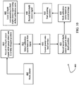
- a process 400 for calibrating the depth sensor 150 is illustrated in FIG. 10 .
- the user preferably raises the toolbar 8 such that the gauge wheel arm 54 lowers to its lowest position against a stop (not shown) provided on the row unit frame 14.
- the monitor 540 preferably records a first depth sensor signal at in this fully-dropped position, which it should be appreciated corresponds to the maximum distance between the magnet 140 and the depth sensor 150.
- monitor 540 preferably selects a calibration curve based on the first depth sensor signal. Multiple calibration curves relating signal level to depth are preferably developed and stored in the memory of the monitor 540; the monitor 540 preferably selects the calibration curve having the minimum signal level closest to the first depth sensor signal recorded at step 410.
- the user preferably lowers the planter onto a hard surface such that the signal generated by the 150 corresponds to the zero-depth signal.
- the monitor 540 preferably records a second depth sensor signal corresponding to the zero-depth position.
- the monitor 540 preferably shifts the calibration curve selected at step 415 such that the zero-depth signal corresponds to the second depth sensor signal.
- the user preferably initiates planting operations such that the opener discs 62 penetrate the soil surface 7.
- the monitor 540 records a third depth sensor signal during planting operations.
- the monitor 540 looks up the depth corresponding to the third depth sensor signal using the calibration curve selected at step 415 and shifted at step 430.
- a process 600 for mapping depth and adjusting downpressure based on measured depth is illustrated in FIG. 11 .
- the monitor 540 records and time-stamps the GPS position of the planter reported by the GPS receiver 550.
- the monitor 540 receives signals from both depth sensors 150-1,150-2 associated with each row unit (or one of the other depth sensor embodiments described herein) and looks up depth measurements corresponding to both signals on a calibration curve (e.g., as in step 445 of process 400).
- the monitor 540 stores and time-stamps the average of both depth measurements (the "measured depth") at each row unit.
- the monitor 540 displays an image correlated to the measured depth on a map at a map location corresponding to the GPS position of the planter at the time of the depth measurements. For example, in some embodiments the monitor 540 displays a legend correlating colors to ranges of depth. In some such embodiments, the depth range less than zero is correlated to a single color while a set of depth ranges greater than zero are correlated to a set of colors such that the color intensity increases with depth.
- the monitor 540 preferably compares the measured depth to the full or desired depth.
- the monitor determines whether the measured depth is equal to (or within a percentage error of) full depth. If measured depth is not equal to full depth, then at step 635 the monitor 540 determines whether the measured depth is less than zero. If the measured depth is less than zero, then at step 640 the monitor 540 preferably adjusts a signal sent to the fluid control system 530 to increase downpressure applied by the actuator 18 by a first increment. If the measured depth is greater than zero, then at step 645 the monitor 540 preferably adjusts a signal sent to the fluid control system 530 to increase downpressure applied by the actuator 18 by a second increment; the second increment is preferably smaller than the first increment.
- the monitor 540 preferably estimates the depth of the trench 3 based on the depth sensor signal.
- the monitor 540 preferably compares the measured depth to a selected depth entered by the user or previously stored in memory. The selected depth may be selected using the methods disclosed in U.S. Provisional Application No. 61/783,591 . If at step 1430 the measured depth is not equal to or within a threshold range (e.g.
- the monitor 540 preferably sends a modified command signal to the depth adjuster 160 in order to bring the measured depth closer to the selected depth; for example, if the measured depth is shallower than the selected depth, then the monitor 540 preferably commands the depth adjuster to rotate the depth adjustment assembly 90 in order to increase the trench depth.
- the single magnet 140 is replaced with an array of magnets arranged radially around the pivot portion 56 of gauge wheel arm 54.
- Each magnet in the array preferably has the opposite polarity of its neighboring magnets.
- a depth sensor is preferably mounted to a sidewall of the row unit frame such that magnets having opposing poles pass by the depth sensor as the gauge wheel arm 54 rotates.
- the depth sensor preferably comprises a Hall-effect sensor such as model no. AS5304 available from Austria Microsystems in 8141 Schloss Premstatten, Austria.
- the depth sensor 150 is replaced with a rotary sensor mounted to the end of a bolt used to secure the gauge wheel arm 54 in position relative to the row unit frame.
- the rotary sensor generates a signal related to the position of the gauge wheel arm 54 relative to the bolt.
- the depth sensor 150 is replaced with a rotary sensor mounted to the row unit frame 14.
- a two-bar linkage preferably connects the gauge wheel arm 54 to the rotary sensor such that the rotary sensor generates a signal related to the position of the gauge wheel arm 54 relative to the row unit frame 14.
- a seed firmer similar to the seed firmer embodiments disclosed in U.S. patent no. 5,425,318 is provided with a depth sensor assembly configured to measure the distance between a soil-engaging portion of the seed firmer and the soil surface 7.
- a linkage is provided between the soil-engaging portion of the seed firmer and a ski or skis configured to ride along the soil surface 7 adjacent to the trench; a Hall-effect or other position sensor is disposed to detect a position of the linkage such that the sensor signal is related to the depth at which the seed firmer engages the bottom of the trench relative to the soil surface.
- a similar sensor is used with a linkage connecting the soil-engaging portion of the seed firmer to the gauge wheel arm 54.
- the depth sensor comprises one of the embodiments disclosed in the '591 application.
- an agricultural row unit comprises a row unit frame, a gauge wheel arm pivotally mounted to the row unit frame and disposed to limit the depth of a trench opened by the row unit, and a sensor configured to generate a signal related to the angular position of said gauge wheel arm relative to said row unit frame.
Landscapes
- Life Sciences & Earth Sciences (AREA)
- Soil Sciences (AREA)
- Environmental Sciences (AREA)
- Engineering & Computer Science (AREA)
- Mechanical Engineering (AREA)
- Physics & Mathematics (AREA)
- General Physics & Mathematics (AREA)
- Lifting Devices For Agricultural Implements (AREA)
- Transplanting Machines (AREA)
- Sowing (AREA)
- Geophysics And Detection Of Objects (AREA)
- Length Measuring Devices With Unspecified Measuring Means (AREA)
Claims (10)
- Verfahren zum Kartieren der Tiefe eines Grabens (3), der durch eine an einem Pflanzgerät befestigten landwirtschaftliche Reiheneinheit (10) in einer Erdoberfläche (7) eines Felds geöffnet wurde, wobei das Verfahren das Folgende aufweist:Empfangen eines Grabentiefensignals von einem der Reiheneinheit (10) zugeordneten Tiefensensor (150; 1226);Bestimmen eines gemessenen Grabentiefenwerts basierend auf dem Grabentiefensignal und einer Kalibrierungskurve;Aufnehmen und Zeitstempeln des Grabentiefenwerts und einer GPS-Position des Pflanzgeräts durch einen GPS-Empfänger (550);Anzeigen eines auf die gemessene Tiefe bezogenen Bilds auf einer Karte an einem Kartenort, der der GPS-Position des Pflanzgeräts zum Zeitpunkt der Tiefenmessung entspricht.
- Verfahren nach Anspruch 1, weiterhin mit dem Folgenden:Vergleichen der gemessenen Grabentiefe mit der gewählten Grabentiefe; undVerändern einer Position eines Tiefenaktuators (18), um die gemessene Grabentiefe der gewählten Grabentiefe anzunähern.
- Verfahren nach Anspruch 1, weiterhin mit dem Folgenden:Vergleichen der gemessenen Grabentiefe mit der gewählten Grabentiefe; undVerändern einer Konfiguration eines Niederhaltedruckventils, um die gemessene Grabentiefe der gewählten Grabentiefe anzunähern.
- Verfahren nach Anspruch 1, weiterhin mit dem Folgenden:Vergleichen der gemessenen Grabentiefe mit einer vollen Tiefe; undfalls die gemessene Grabentiefe nicht gleich einer vollen Tiefe ist: Einstellen des Drucks eines Niederhaltedruckaktuators (18), wobei der Niederhaltedruckaktuator angeordnet ist, um einen auf die landwirtschaftliche Reiheneinheit aufgebrachten Niederhaltedruck zu verändern.
- Verfahren nach Anspruch 4, weiterhin mit dem Folgenden:Bestimmen, ob die gemessene Tiefe kleiner als eine Nulltiefe ist;falls die gemessene Tiefe kleiner als die Nulltiefe ist: Einstellen des Niederhaltedrucks um ein erstes Inkrement; undfalls die gemessene Tiefe nicht kleiner als die Nulltiefe ist: Einstellen des Niederhaltedrucks um ein zweites Inkrement, wobei das erste Inkrement einen anderen Wert als das zweite Inkrement besitzt.
- Verfahren nach Anspruch 1, wobei die landwirtschaftliche Reiheneinheit das Folgende aufweist:einen Rahmen (14);einen Messradarm (54), der schwenkbar an dem Rahmen (14) montiert und angeordnet ist, um die Tiefe des Grabens (3) zu begrenzen; undeinen Sensor (150), der konfiguriert ist, um das Grabentiefensignal zu erzeugen, das auf die Winkelposition des Messradarms (54) relativ zu dem Rahmen (14) bezogen ist.
- Verfahren nach Anspruch 1, wobei die landwirtschaftliche Reiheneinheit das Folgende aufweist:einen Rahmen (14);eine Öffnungsscheibenanordnung (60) mit zwei angewinkelten Öffnungsscheiben (62), die an einem sich nach unten erstreckenden Schaft (15) des Rahmens (14) rollend montiert und angeordnet sind, um einen v-förmigen Graben (3) in der Erdoberfläche (7) zu öffnen;eine Messradanordnung (50) mit zwei Messrädern (52), die mittels zwei Messradarmen (54) an beiden Seiten des Rahmens (14) schwenkbar montiert sind;eine Tiefeneinstellanordnung (90), die schwenkbar an dem Rahmen (14) montiert ist, die die Messradarme (54) kontaktiert, um eine Aufwärtsbewegung der Messradarme (54) zu begrenzen.
- Verfahren nach Anspruch 7, wobei die Kalibrierungskurve in einem Kalibrierungsvorgang ausgewählt wird, wobei der Kalibrierungsvorgang das Folgende aufweist:Speichern einer Mehrzahl von Kalibrierungskurven, die jeweils Grabentiefensignale auf Grabentiefenwerte beziehen;Aufnehmen eines ersten Tiefensensorsignals, während sich ein erster der zwei Messradarme (54) in einer abgesenkten Position befindet; undAuswählen einer ersten Kalibrierungskurve aus der Mehrzahl von Kalibrierungskurven basierend auf dem ersten Tiefensensorsignal.
- Verfahren nach Anspruch 8, wobei der Kalibrierungsvorgang weiterhin das Folgende aufweist:Aufnehmen eines zweiten Tiefensensorsignals, während sich der erste der zwei Messradarme (54) in einer Nulltiefenposition befindet; undVerlagern der ersten Kalibrierungskurve derart, dass ein Nulltiefengrabenwert dem zweiten Tiefensensorsignal entspricht.
- Verfahren nach Anspruch 9, wobei der erste der zwei Messradarme in der Nulltiefenposition platziert ist, indem die landwirtschaftliche Reiheneinheit auf eine Oberfläche abgesenkt wird, wobei die Oberfläche nicht durch die Öffnungsscheiben der landwirtschaftlichen Reiheneinheit durchdrungen wird.
Applications Claiming Priority (3)
| Application Number | Priority Date | Filing Date | Title |
|---|---|---|---|
| US201261718073P | 2012-10-24 | 2012-10-24 | |
| EP13848234.4A EP2911493B1 (de) | 2012-10-24 | 2013-10-24 | Landwirtschaftliche grabentiefenmesssysteme, verfahren und vorrichtung |
| PCT/US2013/066639 WO2014066654A1 (en) | 2012-10-24 | 2013-10-24 | Agricultural trench depth sensing systems, methods, and apparatus |
Related Parent Applications (2)
| Application Number | Title | Priority Date | Filing Date |
|---|---|---|---|
| EP13848234.4A Division-Into EP2911493B1 (de) | 2012-10-24 | 2013-10-24 | Landwirtschaftliche grabentiefenmesssysteme, verfahren und vorrichtung |
| EP13848234.4A Division EP2911493B1 (de) | 2012-10-24 | 2013-10-24 | Landwirtschaftliche grabentiefenmesssysteme, verfahren und vorrichtung |
Publications (2)
| Publication Number | Publication Date |
|---|---|
| EP3659413A1 EP3659413A1 (de) | 2020-06-03 |
| EP3659413B1 true EP3659413B1 (de) | 2021-09-15 |
Family
ID=50545267
Family Applications (3)
| Application Number | Title | Priority Date | Filing Date |
|---|---|---|---|
| EP19215512.5A Active EP3659413B1 (de) | 2012-10-24 | 2013-10-24 | Landwirtschaftliches grabentiefenerfassungsverfahren |
| EP13848234.4A Active EP2911493B1 (de) | 2012-10-24 | 2013-10-24 | Landwirtschaftliche grabentiefenmesssysteme, verfahren und vorrichtung |
| EP19215581.0A Active EP3656196B1 (de) | 2012-10-24 | 2013-10-24 | Landwirtschaftliche grabentiefenerfassungsvorrichtung |
Family Applications After (2)
| Application Number | Title | Priority Date | Filing Date |
|---|---|---|---|
| EP13848234.4A Active EP2911493B1 (de) | 2012-10-24 | 2013-10-24 | Landwirtschaftliche grabentiefenmesssysteme, verfahren und vorrichtung |
| EP19215581.0A Active EP3656196B1 (de) | 2012-10-24 | 2013-10-24 | Landwirtschaftliche grabentiefenerfassungsvorrichtung |
Country Status (9)
| Country | Link |
|---|---|
| US (4) | US9750174B2 (de) |
| EP (3) | EP3659413B1 (de) |
| AR (1) | AR093136A1 (de) |
| AU (4) | AU2013334552B2 (de) |
| BR (1) | BR112015009099B1 (de) |
| CA (4) | CA2888970C (de) |
| UA (2) | UA118546C2 (de) |
| WO (1) | WO2014066654A1 (de) |
| ZA (1) | ZA201503162B (de) |
Families Citing this family (98)
| Publication number | Priority date | Publication date | Assignee | Title |
|---|---|---|---|---|
| HUE034130T2 (en) | 2011-06-03 | 2018-01-29 | Prec Planting Llc | Equipment, systems and procedures for agricultural tools |
| LT3375273T (lt) | 2013-03-14 | 2019-12-27 | Precision Planting Llc | Žemės ūkio padargo vagos gylio reguliavimo ir dirvos būklės stebėsenos sistemos |
| CA2948345C (en) * | 2014-05-08 | 2023-10-31 | Precision Planting Llc | Liquid application apparatus comprising a seed firmer |
| US10785905B2 (en) * | 2014-05-08 | 2020-09-29 | Precision Planting Llc | Liquid application apparatus comprising a seed firmer |
| EP3139725B1 (de) * | 2014-05-09 | 2018-06-06 | Agro Intelligence ApS | Sävorrichtung für sensorbasierte tiefensteuerung beim säen |
| AU2016261331B2 (en) | 2015-05-08 | 2021-03-25 | Climate Llc | Work layer imaging and analysis for implement monitoring, control and operator feedback |
| US10188027B2 (en) * | 2015-05-20 | 2019-01-29 | Kinze Manufacturing, Inc. | Row unit with shank opener |
| US10561059B2 (en) | 2015-06-15 | 2020-02-18 | Precision Planting Llc | Systems, methods, and apparatus for agricultural liquid application |
| US9872425B2 (en) | 2015-07-10 | 2018-01-23 | Cnh Industrial America Llc | System for positioning gauge wheels of an agricultural row unit |
| US9693496B2 (en) * | 2015-09-30 | 2017-07-04 | Deere & Company | Agricultural planting depth sensor |
| WO2017143121A1 (en) | 2016-02-19 | 2017-08-24 | Precision Planting Llc | Agricultural trench depth systems, methods,a nd apparatus |
| CA3189260A1 (en) | 2016-05-13 | 2017-11-16 | Precision Planting Llc | Seed trench closing sensors |
| ES2865552T3 (es) * | 2016-07-22 | 2021-10-15 | Prec Planting Llc | Aparato de detección de profundidad de surco agrícola |
| US11516959B2 (en) | 2017-07-24 | 2022-12-06 | Precision Planting, Llc | Agricultural trench depth sensing systems, methods, and apparatus |
| US12137628B2 (en) * | 2016-07-22 | 2024-11-12 | Precision Planting Llc | Agricultural trench depth sensing systems, methods, and apparatus |
| US10918012B2 (en) * | 2016-09-30 | 2021-02-16 | Deere & Company | Planter row unit furrow depth sensing apparatus and method |
| US10555454B2 (en) | 2016-09-30 | 2020-02-11 | Deere & Company | Planter row unit furrow depth sensing apparatus and method |
| US10687456B2 (en) | 2016-09-30 | 2020-06-23 | Deere & Company | Planter row unit furrow depth sensing apparatus and method |
| US10694658B2 (en) * | 2016-09-30 | 2020-06-30 | Deere & Company | Planter row unit furrow depth sensing apparatus and method |
| US10681859B2 (en) * | 2016-09-30 | 2020-06-16 | Deere & Company | Planter row unit furrow depth sensing apparatus and method |
| US10687457B2 (en) | 2016-09-30 | 2020-06-23 | Deere & Company | Planter row unit furrow depth sensing apparatus and method |
| US10768331B2 (en) | 2016-11-07 | 2020-09-08 | The Climate Corporation | Work layer imaging and analysis for implement monitoring, control and operator feedback |
| US10506756B2 (en) | 2016-12-16 | 2019-12-17 | Agco Corporation | Rotating toolbar with double rod cylinder |
| CA3043794C (en) * | 2016-12-16 | 2024-06-18 | Agco Corporation | Implement contouring toolbar |
| US10512212B2 (en) | 2016-12-19 | 2019-12-24 | The Climate Corporation | Systems, methods, and apparatus for soil and seed monitoring |
| US10444176B2 (en) | 2017-02-17 | 2019-10-15 | Deere & Company | Sensing system for measuring soil properties in real time |
| CN106979767B (zh) * | 2017-03-25 | 2022-09-27 | 南通力联自动化科技有限公司 | 一种用于海滩车的沉陷量检测装置 |
| FR3065146B1 (fr) * | 2017-04-12 | 2019-06-28 | Kuhn S.A. | Procede de reglage en hauteur d'un outil d'usure et machine agricole correspondante |
| US10375878B2 (en) | 2017-04-25 | 2019-08-13 | The Climate Corporation | Plot placement systems and methods |
| US10820475B2 (en) * | 2017-04-27 | 2020-11-03 | Cnh Industrial America Llc | Agricultural implement and procedure for on-the-go soil nitrate testing |
| WO2019023581A1 (en) | 2017-07-28 | 2019-01-31 | Kinze Manufacturing, Inc. | AGRICULTURAL TOOL AND ROW UNITS COMPRISING DOUBLE-ACTING ACTUATION SYSTEMS, METHODS, AND APPARATUS |
| US10779462B2 (en) | 2017-10-13 | 2020-09-22 | Deere & Company | Calibrating an actuator for setting a seed depth for a row unit on a planter |
| US10537055B2 (en) * | 2017-10-13 | 2020-01-21 | Deere & Company | Actuated seed depth setting for a planter row unit |
| US10827663B2 (en) | 2017-10-13 | 2020-11-10 | Deere & Company | Actuator for setting a seed depth for a row unit on a planter |
| US11122731B2 (en) * | 2017-10-31 | 2021-09-21 | Deere & Company | Method of managing planter row unit downforce |
| BR112020008752B1 (pt) | 2017-11-15 | 2023-11-28 | Precision Planting Llc | Sistema para detectar características de uma vala em uma superfície de solo durante as operações de plantação |
| WO2019118758A1 (en) | 2017-12-15 | 2019-06-20 | Kinze Manufacturing, Inc. | Systems, methods, and apparatus for controlling downforce of an agricultural implement |
| US12201044B2 (en) | 2018-02-05 | 2025-01-21 | FarmWise Labs, Inc. | Method for autonomously weeding crops in an agricultural field |
| US10455826B2 (en) | 2018-02-05 | 2019-10-29 | FarmWise Labs, Inc. | Method for autonomously weeding crops in an agricultural field |
| US11277961B2 (en) | 2018-02-09 | 2022-03-22 | Ag Leader Technology | Seed spacing device for an agricultural planter and related systems and methods |
| WO2019164919A1 (en) | 2018-02-20 | 2019-08-29 | Ag Leader Technology | Apparatus, systems and methods for applying fluid |
| US11206754B2 (en) | 2018-02-21 | 2021-12-28 | Deere & Company | Depth sensing with absolute position and temperature compensation |
| US11882782B2 (en) | 2018-03-01 | 2024-01-30 | Precision Planting Llc | Agricultural trench depth systems, methods, and apparatus |
| CN108260378B (zh) * | 2018-03-28 | 2023-10-20 | 吉林大学 | 一种仿蚯蚓波纹润滑体表减阻开沟器 |
| US20190297769A1 (en) | 2018-03-30 | 2019-10-03 | Ag Leader Technology | Devices, Systems, and Methods for Seed Trench Protection |
| US11064653B2 (en) | 2018-06-18 | 2021-07-20 | Ag Leader Technology | Agricultural systems having stalk sensors and data visualization systems and related devices and methods |
| WO2020039312A1 (en) | 2018-08-22 | 2020-02-27 | Precision Planting Llc | Implements and application units having sensors for sensing data to determine agricultural plant characteristics of agricultural fields |
| CN112601450B (zh) | 2018-08-24 | 2024-12-06 | 精密种植有限责任公司 | 农业沟道深度感测系统、方法和装置 |
| US11116123B2 (en) | 2018-08-31 | 2021-09-14 | Cnh Industrial America Llc | System and method of adjusting closing disc penetration depth of a seed-planting implement |
| US11337363B2 (en) | 2018-09-28 | 2022-05-24 | Cnh Industrial America Llc | Calibrating a depth control system of a row unit in an agricultural planter |
| US12520744B2 (en) | 2018-11-15 | 2026-01-13 | Ag Leader Technology | On the go organic matter sensor and associated systems and methods |
| US11147205B2 (en) * | 2019-02-19 | 2021-10-19 | Cnh Industrial America Llc | System and method for monitoring tool float on an agricultural implement |
| US11297768B2 (en) | 2019-02-25 | 2022-04-12 | Ag Leader Technology | Vision based stalk sensors and associated systems and methods |
| US11202404B2 (en) | 2019-03-05 | 2021-12-21 | Deere & Company | Planter row unit downforce control with ground view sensor |
| US11134606B2 (en) | 2019-03-08 | 2021-10-05 | Deere & Company | Planter row unit with load sensing depth stop assembly |
| CN109883383A (zh) * | 2019-03-15 | 2019-06-14 | 陈瑞言 | 一种土壤深度测量装置及其使用方法 |
| EP3729934A1 (de) | 2019-04-25 | 2020-10-28 | CNH Industrial Sweden AB | Pflug |
| US11310953B2 (en) | 2019-07-02 | 2022-04-26 | Cnh Industrial America Llc | System and method for calibrating load sensors of an agricultural implement |
| WO2021014231A1 (en) | 2019-07-24 | 2021-01-28 | Precision Planting Llc | Agricultural implements and method of planting |
| US12495736B2 (en) * | 2019-09-04 | 2025-12-16 | Ag Leader Technology | Apparatus, systems and methods for stalk sensing |
| GB201913215D0 (en) | 2019-09-13 | 2019-10-30 | Agco Int Gmbh | Harvesting headers having leading sensors, agricultural machines carrying such headers, and related methods |
| AU2020358931B2 (en) | 2019-10-03 | 2025-06-26 | Precision Planting Llc | Agricultural trench depth systems, methods, and apparatus |
| US12029146B2 (en) | 2019-10-30 | 2024-07-09 | Deere & Company | Implement having weight transfer system and method of operating the same |
| US11470763B2 (en) | 2019-11-07 | 2022-10-18 | Cnh Industrial Canada, Ltd. | System and method for determining subsurface soil layer characteristics based on RADAR and load data |
| US11553638B2 (en) | 2019-12-24 | 2023-01-17 | Cnh Industrial America Llc | Particle delivery system of an agricultural row unit |
| US11564344B2 (en) | 2019-12-24 | 2023-01-31 | Cnh Industrial America Llc | Particle delivery system of an agricultural row unit |
| US11564346B2 (en) | 2019-12-24 | 2023-01-31 | Cnh Industrial America Llc | Particle delivery system of an agricultural row unit |
| US11596095B2 (en) | 2019-12-24 | 2023-03-07 | Cnh Industrial America Llc | Particle delivery system of an agricultural row unit |
| US11553639B2 (en) | 2019-12-24 | 2023-01-17 | Cnh Industrial America Llc | Particle delivery system of an agricultural row unit |
| US11523555B2 (en) | 2019-12-24 | 2022-12-13 | Cnh Industrial America Llc | Particle delivery system of an agricultural row unit |
| US11516958B2 (en) | 2019-12-24 | 2022-12-06 | Cnh Industrial America Llc | Particle delivery system of an agricultural row unit |
| US11582899B2 (en) | 2019-12-24 | 2023-02-21 | Cnh Industrial America Llc | Particle delivery system of an agricultural row unit |
| US11483963B2 (en) | 2019-12-24 | 2022-11-01 | Cnh Industrial America Llc | Particle delivery system of an agricultural row unit |
| US11523556B2 (en) | 2019-12-24 | 2022-12-13 | Cnh Industrial America Llc | Particle delivery system of an agricultural row unit |
| US11589500B2 (en) | 2019-12-24 | 2023-02-28 | Cnh Industrial America Llc | Particle delivery system of an agricultural row unit |
| US11490558B2 (en) | 2019-12-24 | 2022-11-08 | Cnh Industrial America Llc | Particle delivery system of an agricultural row unit |
| US12268115B2 (en) | 2020-02-07 | 2025-04-08 | Ag Leader Technology | Planter obstruction monitoring and associated devices and methods |
| US11602092B2 (en) | 2020-03-26 | 2023-03-14 | Cnh Industrial America Llc | Frame control system for an agricultural implement |
| US11617294B2 (en) | 2020-03-26 | 2023-04-04 | Cnh Industrial America Llc | Orientation control system for an agricultural implement |
| US11558993B2 (en) | 2020-03-26 | 2023-01-24 | Cnh Industrial America Llc | Soil monitoring system for an agricultural tillage implement |
| US11638393B2 (en) | 2020-03-26 | 2023-05-02 | Cnh Industrial America Llc | Ground engaging tool monitoring system |
| US11730076B2 (en) | 2020-03-26 | 2023-08-22 | Cnh Industrial America Llc | Control system for an agricultural implement |
| US12022756B2 (en) | 2020-03-26 | 2024-07-02 | Cnh Industrial America Llc | Orientation control system for an agricultural implement |
| US12507627B2 (en) | 2020-04-08 | 2025-12-30 | Ag Leader Technology | Method for warning of a shelled ear event |
| US11576293B2 (en) * | 2020-07-06 | 2023-02-14 | Blake Paul Patton | Agricultural planter depth calibration block |
| DE102020121100A1 (de) * | 2020-08-11 | 2022-02-17 | Horsch Maschinen Gmbh | System und Verfahren für eine landwirtschaftliche Verteilmaschine und landwirtschaftliche Verteilmaschine |
| US12414505B2 (en) | 2020-09-04 | 2025-09-16 | Ag Leader Technology | Harvesting system for row-by-row control of a harvester |
| US12477973B2 (en) | 2020-11-13 | 2025-11-25 | Ag Leader Technology | Agricultural high speed row unit |
| SE547533C2 (sv) * | 2021-07-09 | 2025-10-14 | Vaederstad Holding Ab | Förfarande för kalibrering av lantbruksredskap samt lantbruksredskap |
| CN113519238A (zh) * | 2021-07-12 | 2021-10-22 | 安徽建筑大学 | 一种播种深度检测装置及检测方法 |
| US12543630B2 (en) | 2021-07-21 | 2026-02-10 | Kinze Manufacturing, Inc. | Row unit component mounting systems, methods, and apparatus for agricultural implements |
| DE102021125916A1 (de) | 2021-10-06 | 2023-04-06 | Amazonen-Werke H. Dreyer SE & Co. KG | Reiheneinheit für eine landwirtschaftliche Verteilmaschine und Verfahren zum Ablegen von granularem Material |
| US12298443B2 (en) | 2021-12-15 | 2025-05-13 | Cnh Industrial America Llc | System and method for calibrating agricultural field surface profile sensors |
| US20230337569A1 (en) * | 2022-04-20 | 2023-10-26 | Cnh Industrial America Llc | Agricultural system and method for determining a position of a gauge wheel of a row unit for a seed-planting implement |
| US12543626B2 (en) | 2022-04-21 | 2026-02-10 | Cnh Industrial America Llc | System and method for controlling row cleaner positioning on a seed-planting implement |
| US12550811B2 (en) | 2022-06-30 | 2026-02-17 | Cnh Industrial America Llc | Agricultural row unit system and method |
| US12317766B2 (en) * | 2022-12-21 | 2025-06-03 | Cnh Industrial America Llc | Central press wheel inflation system |
| US12120973B2 (en) | 2023-02-07 | 2024-10-22 | FarmWise Labs, Inc. | Crop detection system and/or method |
Family Cites Families (57)
| Publication number | Priority date | Publication date | Assignee | Title |
|---|---|---|---|---|
| US4413685A (en) * | 1979-12-11 | 1983-11-08 | Gremelspacher Philip E | Planter implement with adjusting position-display apparatus and system thereof |
| CA1254286A (en) | 1985-12-05 | 1989-05-16 | Tetsuya Nishida | Plowing depth detecting system for rotary plow |
| DE3612763A1 (de) * | 1986-04-16 | 1987-10-22 | Bosch Gmbh Robert | Elektrohydraulische hubwerks-regeleinrichtung |
| US4723608A (en) * | 1986-09-30 | 1988-02-09 | Deere & Company | Depth sensing skid assembly |
| JPH0269104A (ja) | 1988-09-01 | 1990-03-08 | Iseki & Co Ltd | トラクタに於ける耕深制御装置 |
| JP2885543B2 (ja) | 1991-06-05 | 1999-04-26 | ヤンマーディーゼル株式会社 | トラクタの耕深制御機構 |
| US5875108A (en) | 1991-12-23 | 1999-02-23 | Hoffberg; Steven M. | Ergonomic man-machine interface incorporating adaptive pattern recognition based control system |
| JP3195651B2 (ja) | 1992-06-30 | 2001-08-06 | 株式会社クボタ | 苗植付装置の昇降制御機構 |
| US5437294A (en) | 1993-03-04 | 1995-08-01 | Lir-Usa Manufacturing Co., Inc. | Compact with rotatable panel in base and/or cover |
| US5425318A (en) | 1994-02-14 | 1995-06-20 | J & K Keeton Enterprises, Inc. | Resilient seed firming attachment for a planting machine |
| JP3078994B2 (ja) | 1994-12-19 | 2000-08-21 | 株式会社クボタ | 農用トラクタのロータリ耕耘装置昇降構造 |
| JPH08331914A (ja) * | 1995-06-09 | 1996-12-17 | Kubota Corp | 湛水直播機 |
| US5553407A (en) * | 1995-06-19 | 1996-09-10 | Vermeer Manufacturing Company | Excavator data acquisition and control system and method of use |
| NL1001693C2 (nl) * | 1995-11-20 | 1997-05-21 | Maasland Nv | Grondbewerkingswerktuig, voertuig daarvoor, dan wel combinatie daarvan. |
| US6070539A (en) | 1997-03-21 | 2000-06-06 | Case Corporation | Variable rate agricultural product application implement with multiple inputs and feedback |
| US6302220B1 (en) * | 1999-10-28 | 2001-10-16 | Flexi-Coil Ltd. | Agricultural ground working implement with hydraulic downpressure circuit |
| JP2001299010A (ja) | 2000-04-26 | 2001-10-30 | Iseki & Co Ltd | トラクタの耕深制御装置 |
| DE10133191A1 (de) | 2001-07-07 | 2003-01-16 | Deere & Co | Landwirtschaftliche Bestellkombination |
| US6729050B2 (en) * | 2001-08-31 | 2004-05-04 | Vermeer Manufacturing Company | Control of excavation apparatus |
| US6389999B1 (en) * | 2001-11-02 | 2002-05-21 | Dennis Duello | Dynamic controller of excess downpressure for surface engaging implement |
| US6671698B2 (en) * | 2002-03-20 | 2003-12-30 | Deere & Company | Method and system for automated tracing of an agricultural product |
| US6997120B2 (en) * | 2003-05-15 | 2006-02-14 | Robert Gabriel | Planting apparatus and method |
| US7113105B2 (en) * | 2003-08-28 | 2006-09-26 | Caterpillar Inc. | Work machine display system |
| US7044070B2 (en) * | 2004-02-05 | 2006-05-16 | Kasco Manufacturing Company, Inc. | Seed drill with walking beam assembly |
| DE102004011302A1 (de) | 2004-03-09 | 2005-09-22 | Amazonen-Werke H. Dreyer Gmbh & Co. Kg | Elektronische Überwachungseinrichtung |
| US8308075B2 (en) * | 2005-04-19 | 2012-11-13 | Kamterter Products, Llc | Systems for the control and use of fluids and particles |
| US20080125942A1 (en) * | 2006-06-30 | 2008-05-29 | Page Tucker | System and method for digging navigation |
| WO2008008345A2 (en) * | 2006-07-14 | 2008-01-17 | Martin Howard D | Apparatus for planter depth monitoring |
| US7360494B2 (en) | 2006-07-14 | 2008-04-22 | Howard D. Martin | Apparatus for planter depth monitoring |
| US7360495B1 (en) | 2006-12-18 | 2008-04-22 | Howard D. Martin | Method for planter depth monitoring |
| US7634863B2 (en) * | 2006-11-30 | 2009-12-22 | Caterpillar Inc. | Repositioning assist for an excavating operation |
| US7865285B2 (en) * | 2006-12-27 | 2011-01-04 | Caterpillar Inc | Machine control system and method |
| CN201072894Y (zh) | 2007-06-22 | 2008-06-18 | 福田雷沃国际重工股份有限公司 | 拖拉机用耕深提升器 |
| CN101080968A (zh) | 2007-06-22 | 2007-12-05 | 福田雷沃国际重工股份有限公司 | 拖拉机用耕深提升器 |
| US7717048B2 (en) * | 2007-10-09 | 2010-05-18 | Deere & Company | Agricultural seeding system |
| US8817238B2 (en) * | 2007-10-26 | 2014-08-26 | Deere & Company | Three dimensional feature location from an excavator |
| EP2232195B1 (de) * | 2007-12-14 | 2015-03-18 | Zygo Corporation | Analyse der oberflächenstruktur unter verwendung von rasterinterferometrie |
| CZ2008273A3 (cs) * | 2008-05-02 | 2008-10-01 | Farmet, A. S. | Zarízení pro regulaci polohy zavlacovace |
| US7946232B2 (en) * | 2009-07-13 | 2011-05-24 | Agco Corporation | Planter with depth adjustment mechanism |
| US7997218B2 (en) * | 2009-07-20 | 2011-08-16 | Landoll Corporation | Soil strip assembly for seed drill row unit |
| US10285325B2 (en) * | 2010-07-02 | 2019-05-14 | Deere & Company | Seeding apparatus and method of determining a seed spacing variability value |
| WO2012015957A1 (en) * | 2010-07-27 | 2012-02-02 | Precision Planting, Inc. | Seeding control system and method |
| US8418636B2 (en) * | 2010-08-20 | 2013-04-16 | Deere & Company | In-ground seed spacing monitoring system for use in an agricultural seeder |
| US9232687B2 (en) * | 2010-09-15 | 2016-01-12 | Dawn Equipment Company | Agricultural systems |
| HUE043412T2 (hu) * | 2010-11-10 | 2019-08-28 | Dellcron Innovation Ab | Eljárás legalább egy csõ/kommunikációs kábel elhelyezésére egy út felszíne alatt egy területen |
| US8634992B2 (en) * | 2011-01-26 | 2014-01-21 | Precision Planting Llc | Dynamic supplemental downforce control system for planter row units |
| WO2012129442A2 (en) | 2011-03-22 | 2012-09-27 | Precision Planting, Inc. | Seed meter |
| US20120265410A1 (en) * | 2011-03-25 | 2012-10-18 | Graham Toby E | Method and apparatus for controlling seed population |
| WO2012149415A1 (en) | 2011-04-27 | 2012-11-01 | Kinze Manufacturing, Inc. | Remote adjustment of a row unit of an agricultural device |
| RU2581217C2 (ru) | 2011-04-27 | 2016-04-20 | Кинз Мэньюфэкчеринг, Инк. | Устройства сельскохозяйственного назначения, системы и способы определения характеристик почвы и семян и их анализа |
| WO2012149367A1 (en) * | 2011-04-27 | 2012-11-01 | Kinze Manufacturing, Inc. | Down and/or up force adjustment system |
| US8918463B2 (en) | 2011-04-29 | 2014-12-23 | Facebook, Inc. | Automated event tagging |
| HUE034130T2 (en) * | 2011-06-03 | 2018-01-29 | Prec Planting Llc | Equipment, systems and procedures for agricultural tools |
| KR101842257B1 (ko) | 2011-09-14 | 2018-05-15 | 삼성전자주식회사 | 신호 처리 방법, 그에 따른 엔코딩 장치, 및 그에 따른 디코딩 장치 |
| US9433142B2 (en) * | 2011-11-08 | 2016-09-06 | Buhler Ezee-On Inc. | Tool control system for agricultural seeders |
| US20140089045A1 (en) * | 2012-09-27 | 2014-03-27 | Superior Edge, Inc. | Methods, apparatus and systems for determining stand population, stand consistency and stand quality in an agricultural crop and alerting users |
| US9629304B2 (en) * | 2013-04-08 | 2017-04-25 | Ag Leader Technology | On-the go soil sensors and control methods for agricultural machines |
-
2013
- 2013-10-24 EP EP19215512.5A patent/EP3659413B1/de active Active
- 2013-10-24 US US14/437,985 patent/US9750174B2/en active Active
- 2013-10-24 EP EP13848234.4A patent/EP2911493B1/de active Active
- 2013-10-24 CA CA2888970A patent/CA2888970C/en active Active
- 2013-10-24 AU AU2013334552A patent/AU2013334552B2/en not_active Ceased
- 2013-10-24 CA CA3204747A patent/CA3204747A1/en active Pending
- 2013-10-24 EP EP19215581.0A patent/EP3656196B1/de active Active
- 2013-10-24 UA UAA201504987A patent/UA118546C2/uk unknown
- 2013-10-24 BR BR112015009099-0A patent/BR112015009099B1/pt active IP Right Grant
- 2013-10-24 AR ARP130103883A patent/AR093136A1/es active IP Right Grant
- 2013-10-24 CA CA3077900A patent/CA3077900C/en active Active
- 2013-10-24 CA CA3077902A patent/CA3077902C/en active Active
- 2013-10-24 UA UAA201809702A patent/UA125643C2/uk unknown
- 2013-10-24 WO PCT/US2013/066639 patent/WO2014066654A1/en not_active Ceased
-
2015
- 2015-05-07 ZA ZA2015/03162A patent/ZA201503162B/en unknown
-
2017
- 2017-09-01 US US15/694,432 patent/US10455756B2/en active Active
- 2017-09-01 US US15/694,485 patent/US10506758B2/en active Active
- 2017-10-17 AU AU2017248423A patent/AU2017248423B2/en active Active
-
2019
- 2019-01-16 US US16/249,894 patent/US11140808B2/en active Active
-
2020
- 2020-02-28 AU AU2020201505A patent/AU2020201505B2/en not_active Ceased
-
2021
- 2021-08-04 AU AU2021212020A patent/AU2021212020B2/en active Active
Also Published As
Similar Documents
| Publication | Publication Date | Title |
|---|---|---|
| AU2021212020B2 (en) | Agricultural trench depth sensing systems, methods, and apparatus | |
| US11882782B2 (en) | Agricultural trench depth systems, methods, and apparatus | |
| EP4241547B1 (de) | Landwirtschaftliche grabentiefenerfassungssystem | |
| US12279546B2 (en) | Agricultural trench depth sensing systems, methods, and apparatus | |
| US11516959B2 (en) | Agricultural trench depth sensing systems, methods, and apparatus |
Legal Events
| Date | Code | Title | Description |
|---|---|---|---|
| PUAI | Public reference made under article 153(3) epc to a published international application that has entered the european phase |
Free format text: ORIGINAL CODE: 0009012 |
|
| STAA | Information on the status of an ep patent application or granted ep patent |
Free format text: STATUS: THE APPLICATION HAS BEEN PUBLISHED |
|
| AC | Divisional application: reference to earlier application |
Ref document number: 2911493 Country of ref document: EP Kind code of ref document: P |
|
| AK | Designated contracting states |
Kind code of ref document: A1 Designated state(s): AL AT BE BG CH CY CZ DE DK EE ES FI FR GB GR HR HU IE IS IT LI LT LU LV MC MK MT NL NO PL PT RO RS SE SI SK SM TR |
|
| STAA | Information on the status of an ep patent application or granted ep patent |
Free format text: STATUS: REQUEST FOR EXAMINATION WAS MADE |
|
| 17P | Request for examination filed |
Effective date: 20201203 |
|
| RBV | Designated contracting states (corrected) |
Designated state(s): AL AT BE BG CH CY CZ DE DK EE ES FI FR GB GR HR HU IE IS IT LI LT LU LV MC MK MT NL NO PL PT RO RS SE SI SK SM TR |
|
| GRAP | Despatch of communication of intention to grant a patent |
Free format text: ORIGINAL CODE: EPIDOSNIGR1 |
|
| STAA | Information on the status of an ep patent application or granted ep patent |
Free format text: STATUS: GRANT OF PATENT IS INTENDED |
|
| RIC1 | Information provided on ipc code assigned before grant |
Ipc: A01C 7/20 20060101ALI20210414BHEP Ipc: A01B 79/00 20060101ALI20210414BHEP Ipc: A01B 63/00 20060101AFI20210414BHEP |
|
| INTG | Intention to grant announced |
Effective date: 20210512 |
|
| GRAS | Grant fee paid |
Free format text: ORIGINAL CODE: EPIDOSNIGR3 |
|
| GRAA | (expected) grant |
Free format text: ORIGINAL CODE: 0009210 |
|
| STAA | Information on the status of an ep patent application or granted ep patent |
Free format text: STATUS: THE PATENT HAS BEEN GRANTED |
|
| AC | Divisional application: reference to earlier application |
Ref document number: 2911493 Country of ref document: EP Kind code of ref document: P |
|
| AK | Designated contracting states |
Kind code of ref document: B1 Designated state(s): AL AT BE BG CH CY CZ DE DK EE ES FI FR GB GR HR HU IE IS IT LI LT LU LV MC MK MT NL NO PL PT RO RS SE SI SK SM TR |
|
| REG | Reference to a national code |
Ref country code: CH Ref legal event code: EP |
|
| REG | Reference to a national code |
Ref country code: DE Ref legal event code: R096 Ref document number: 602013079315 Country of ref document: DE |
|
| REG | Reference to a national code |
Ref country code: IE Ref legal event code: FG4D |
|
| REG | Reference to a national code |
Ref country code: AT Ref legal event code: REF Ref document number: 1429773 Country of ref document: AT Kind code of ref document: T Effective date: 20211015 |
|
| REG | Reference to a national code |
Ref country code: LT Ref legal event code: MG9D |
|
| REG | Reference to a national code |
Ref country code: NL Ref legal event code: MP Effective date: 20210915 |
|
| PG25 | Lapsed in a contracting state [announced via postgrant information from national office to epo] |
Ref country code: SE Free format text: LAPSE BECAUSE OF FAILURE TO SUBMIT A TRANSLATION OF THE DESCRIPTION OR TO PAY THE FEE WITHIN THE PRESCRIBED TIME-LIMIT Effective date: 20210915 Ref country code: RS Free format text: LAPSE BECAUSE OF FAILURE TO SUBMIT A TRANSLATION OF THE DESCRIPTION OR TO PAY THE FEE WITHIN THE PRESCRIBED TIME-LIMIT Effective date: 20210915 Ref country code: FI Free format text: LAPSE BECAUSE OF FAILURE TO SUBMIT A TRANSLATION OF THE DESCRIPTION OR TO PAY THE FEE WITHIN THE PRESCRIBED TIME-LIMIT Effective date: 20210915 Ref country code: HR Free format text: LAPSE BECAUSE OF FAILURE TO SUBMIT A TRANSLATION OF THE DESCRIPTION OR TO PAY THE FEE WITHIN THE PRESCRIBED TIME-LIMIT Effective date: 20210915 Ref country code: NO Free format text: LAPSE BECAUSE OF FAILURE TO SUBMIT A TRANSLATION OF THE DESCRIPTION OR TO PAY THE FEE WITHIN THE PRESCRIBED TIME-LIMIT Effective date: 20211215 Ref country code: BG Free format text: LAPSE BECAUSE OF FAILURE TO SUBMIT A TRANSLATION OF THE DESCRIPTION OR TO PAY THE FEE WITHIN THE PRESCRIBED TIME-LIMIT Effective date: 20211215 Ref country code: LT Free format text: LAPSE BECAUSE OF FAILURE TO SUBMIT A TRANSLATION OF THE DESCRIPTION OR TO PAY THE FEE WITHIN THE PRESCRIBED TIME-LIMIT Effective date: 20210915 |
|
| REG | Reference to a national code |
Ref country code: AT Ref legal event code: MK05 Ref document number: 1429773 Country of ref document: AT Kind code of ref document: T Effective date: 20210915 |
|
| PG25 | Lapsed in a contracting state [announced via postgrant information from national office to epo] |
Ref country code: LV Free format text: LAPSE BECAUSE OF FAILURE TO SUBMIT A TRANSLATION OF THE DESCRIPTION OR TO PAY THE FEE WITHIN THE PRESCRIBED TIME-LIMIT Effective date: 20210915 Ref country code: GR Free format text: LAPSE BECAUSE OF FAILURE TO SUBMIT A TRANSLATION OF THE DESCRIPTION OR TO PAY THE FEE WITHIN THE PRESCRIBED TIME-LIMIT Effective date: 20211216 |
|
| PG25 | Lapsed in a contracting state [announced via postgrant information from national office to epo] |
Ref country code: AT Free format text: LAPSE BECAUSE OF FAILURE TO SUBMIT A TRANSLATION OF THE DESCRIPTION OR TO PAY THE FEE WITHIN THE PRESCRIBED TIME-LIMIT Effective date: 20210915 |
|
| REG | Reference to a national code |
Ref country code: CH Ref legal event code: PL |
|
| PG25 | Lapsed in a contracting state [announced via postgrant information from national office to epo] |
Ref country code: IS Free format text: LAPSE BECAUSE OF FAILURE TO SUBMIT A TRANSLATION OF THE DESCRIPTION OR TO PAY THE FEE WITHIN THE PRESCRIBED TIME-LIMIT Effective date: 20220115 Ref country code: SM Free format text: LAPSE BECAUSE OF FAILURE TO SUBMIT A TRANSLATION OF THE DESCRIPTION OR TO PAY THE FEE WITHIN THE PRESCRIBED TIME-LIMIT Effective date: 20210915 Ref country code: SK Free format text: LAPSE BECAUSE OF FAILURE TO SUBMIT A TRANSLATION OF THE DESCRIPTION OR TO PAY THE FEE WITHIN THE PRESCRIBED TIME-LIMIT Effective date: 20210915 Ref country code: RO Free format text: LAPSE BECAUSE OF FAILURE TO SUBMIT A TRANSLATION OF THE DESCRIPTION OR TO PAY THE FEE WITHIN THE PRESCRIBED TIME-LIMIT Effective date: 20210915 Ref country code: PT Free format text: LAPSE BECAUSE OF FAILURE TO SUBMIT A TRANSLATION OF THE DESCRIPTION OR TO PAY THE FEE WITHIN THE PRESCRIBED TIME-LIMIT Effective date: 20220117 Ref country code: PL Free format text: LAPSE BECAUSE OF FAILURE TO SUBMIT A TRANSLATION OF THE DESCRIPTION OR TO PAY THE FEE WITHIN THE PRESCRIBED TIME-LIMIT Effective date: 20210915 Ref country code: NL Free format text: LAPSE BECAUSE OF FAILURE TO SUBMIT A TRANSLATION OF THE DESCRIPTION OR TO PAY THE FEE WITHIN THE PRESCRIBED TIME-LIMIT Effective date: 20210915 Ref country code: ES Free format text: LAPSE BECAUSE OF FAILURE TO SUBMIT A TRANSLATION OF THE DESCRIPTION OR TO PAY THE FEE WITHIN THE PRESCRIBED TIME-LIMIT Effective date: 20210915 Ref country code: EE Free format text: LAPSE BECAUSE OF FAILURE TO SUBMIT A TRANSLATION OF THE DESCRIPTION OR TO PAY THE FEE WITHIN THE PRESCRIBED TIME-LIMIT Effective date: 20210915 Ref country code: CZ Free format text: LAPSE BECAUSE OF FAILURE TO SUBMIT A TRANSLATION OF THE DESCRIPTION OR TO PAY THE FEE WITHIN THE PRESCRIBED TIME-LIMIT Effective date: 20210915 Ref country code: AL Free format text: LAPSE BECAUSE OF FAILURE TO SUBMIT A TRANSLATION OF THE DESCRIPTION OR TO PAY THE FEE WITHIN THE PRESCRIBED TIME-LIMIT Effective date: 20210915 |
|
| REG | Reference to a national code |
Ref country code: DE Ref legal event code: R097 Ref document number: 602013079315 Country of ref document: DE |
|
| REG | Reference to a national code |
Ref country code: BE Ref legal event code: MM Effective date: 20211031 |
|
| PG25 | Lapsed in a contracting state [announced via postgrant information from national office to epo] |
Ref country code: MC Free format text: LAPSE BECAUSE OF FAILURE TO SUBMIT A TRANSLATION OF THE DESCRIPTION OR TO PAY THE FEE WITHIN THE PRESCRIBED TIME-LIMIT Effective date: 20210915 |
|
| PLBE | No opposition filed within time limit |
Free format text: ORIGINAL CODE: 0009261 |
|
| STAA | Information on the status of an ep patent application or granted ep patent |
Free format text: STATUS: NO OPPOSITION FILED WITHIN TIME LIMIT |
|
| PG25 | Lapsed in a contracting state [announced via postgrant information from national office to epo] |
Ref country code: LU Free format text: LAPSE BECAUSE OF NON-PAYMENT OF DUE FEES Effective date: 20211024 Ref country code: DK Free format text: LAPSE BECAUSE OF FAILURE TO SUBMIT A TRANSLATION OF THE DESCRIPTION OR TO PAY THE FEE WITHIN THE PRESCRIBED TIME-LIMIT Effective date: 20210915 Ref country code: BE Free format text: LAPSE BECAUSE OF NON-PAYMENT OF DUE FEES Effective date: 20211031 |
|
| 26N | No opposition filed |
Effective date: 20220616 |
|
| GBPC | Gb: european patent ceased through non-payment of renewal fee |
Effective date: 20211215 |
|
| PG25 | Lapsed in a contracting state [announced via postgrant information from national office to epo] |
Ref country code: SI Free format text: LAPSE BECAUSE OF FAILURE TO SUBMIT A TRANSLATION OF THE DESCRIPTION OR TO PAY THE FEE WITHIN THE PRESCRIBED TIME-LIMIT Effective date: 20210915 Ref country code: LI Free format text: LAPSE BECAUSE OF NON-PAYMENT OF DUE FEES Effective date: 20211031 Ref country code: CH Free format text: LAPSE BECAUSE OF NON-PAYMENT OF DUE FEES Effective date: 20211031 |
|
| PG25 | Lapsed in a contracting state [announced via postgrant information from national office to epo] |
Ref country code: IE Free format text: LAPSE BECAUSE OF NON-PAYMENT OF DUE FEES Effective date: 20211024 Ref country code: GB Free format text: LAPSE BECAUSE OF NON-PAYMENT OF DUE FEES Effective date: 20211215 |
|
| P01 | Opt-out of the competence of the unified patent court (upc) registered |
Effective date: 20230518 |
|
| PG25 | Lapsed in a contracting state [announced via postgrant information from national office to epo] |
Ref country code: CY Free format text: LAPSE BECAUSE OF FAILURE TO SUBMIT A TRANSLATION OF THE DESCRIPTION OR TO PAY THE FEE WITHIN THE PRESCRIBED TIME-LIMIT Effective date: 20210915 |
|
| PG25 | Lapsed in a contracting state [announced via postgrant information from national office to epo] |
Ref country code: HU Free format text: LAPSE BECAUSE OF FAILURE TO SUBMIT A TRANSLATION OF THE DESCRIPTION OR TO PAY THE FEE WITHIN THE PRESCRIBED TIME-LIMIT; INVALID AB INITIO Effective date: 20131024 |
|
| PG25 | Lapsed in a contracting state [announced via postgrant information from national office to epo] |
Ref country code: MK Free format text: LAPSE BECAUSE OF FAILURE TO SUBMIT A TRANSLATION OF THE DESCRIPTION OR TO PAY THE FEE WITHIN THE PRESCRIBED TIME-LIMIT Effective date: 20210915 |
|
| PG25 | Lapsed in a contracting state [announced via postgrant information from national office to epo] |
Ref country code: TR Free format text: LAPSE BECAUSE OF FAILURE TO SUBMIT A TRANSLATION OF THE DESCRIPTION OR TO PAY THE FEE WITHIN THE PRESCRIBED TIME-LIMIT Effective date: 20210915 |
|
| PG25 | Lapsed in a contracting state [announced via postgrant information from national office to epo] |
Ref country code: MT Free format text: LAPSE BECAUSE OF FAILURE TO SUBMIT A TRANSLATION OF THE DESCRIPTION OR TO PAY THE FEE WITHIN THE PRESCRIBED TIME-LIMIT Effective date: 20210915 |
|
| PGFP | Annual fee paid to national office [announced via postgrant information from national office to epo] |
Ref country code: DE Payment date: 20251021 Year of fee payment: 13 |
|
| PGFP | Annual fee paid to national office [announced via postgrant information from national office to epo] |
Ref country code: IT Payment date: 20251021 Year of fee payment: 13 |
|
| PGFP | Annual fee paid to national office [announced via postgrant information from national office to epo] |
Ref country code: FR Payment date: 20251030 Year of fee payment: 13 |