EP3659379B1 - Vorrichung und verfahren zur strahlausfallwiederherstellung - Google Patents
Vorrichung und verfahren zur strahlausfallwiederherstellung Download PDFInfo
- Publication number
- EP3659379B1 EP3659379B1 EP18854993.5A EP18854993A EP3659379B1 EP 3659379 B1 EP3659379 B1 EP 3659379B1 EP 18854993 A EP18854993 A EP 18854993A EP 3659379 B1 EP3659379 B1 EP 3659379B1
- Authority
- EP
- European Patent Office
- Prior art keywords
- brach
- user equipment
- resource
- resources
- block
- Prior art date
- Legal status (The legal status is an assumption and is not a legal conclusion. Google has not performed a legal analysis and makes no representation as to the accuracy of the status listed.)
- Active
Links
- 238000000034 method Methods 0.000 title claims description 38
- 238000011084 recovery Methods 0.000 title claims description 23
- 238000004891 communication Methods 0.000 claims description 21
- 230000015654 memory Effects 0.000 claims description 21
- 238000001514 detection method Methods 0.000 claims description 17
- 238000004590 computer program Methods 0.000 claims description 5
- 230000005055 memory storage Effects 0.000 claims description 2
- 230000005540 biological transmission Effects 0.000 description 23
- 238000012545 processing Methods 0.000 description 22
- 238000010586 diagram Methods 0.000 description 10
- 238000005516 engineering process Methods 0.000 description 7
- 238000013468 resource allocation Methods 0.000 description 7
- 101150069124 RAN1 gene Proteins 0.000 description 4
- 101100355633 Salmo salar ran gene Proteins 0.000 description 4
- 238000012544 monitoring process Methods 0.000 description 4
- 238000013507 mapping Methods 0.000 description 3
- 230000007246 mechanism Effects 0.000 description 3
- 238000010295 mobile communication Methods 0.000 description 3
- 230000003287 optical effect Effects 0.000 description 3
- 230000000737 periodic effect Effects 0.000 description 3
- 230000008569 process Effects 0.000 description 3
- 230000008054 signal transmission Effects 0.000 description 3
- 230000001413 cellular effect Effects 0.000 description 2
- 230000007774 longterm Effects 0.000 description 2
- 238000005259 measurement Methods 0.000 description 2
- 239000007787 solid Substances 0.000 description 2
- 101000878595 Arabidopsis thaliana Squalene synthase 1 Proteins 0.000 description 1
- 101000741965 Homo sapiens Inactive tyrosine-protein kinase PRAG1 Proteins 0.000 description 1
- 102100038659 Inactive tyrosine-protein kinase PRAG1 Human genes 0.000 description 1
- 230000010267 cellular communication Effects 0.000 description 1
- 238000007796 conventional method Methods 0.000 description 1
- 239000013256 coordination polymer Substances 0.000 description 1
- 238000013500 data storage Methods 0.000 description 1
- 238000006073 displacement reaction Methods 0.000 description 1
- 230000006870 function Effects 0.000 description 1
- 230000010354 integration Effects 0.000 description 1
- 230000003993 interaction Effects 0.000 description 1
- 238000007726 management method Methods 0.000 description 1
- 239000011159 matrix material Substances 0.000 description 1
- 238000012986 modification Methods 0.000 description 1
- 230000004048 modification Effects 0.000 description 1
- 230000002093 peripheral effect Effects 0.000 description 1
- 230000011664 signaling Effects 0.000 description 1
- 230000003068 static effect Effects 0.000 description 1
- 238000010408 sweeping Methods 0.000 description 1
- 230000001360 synchronised effect Effects 0.000 description 1
Images


Classifications
-
- H—ELECTRICITY
- H04—ELECTRIC COMMUNICATION TECHNIQUE
- H04B—TRANSMISSION
- H04B7/00—Radio transmission systems, i.e. using radiation field
- H04B7/02—Diversity systems; Multi-antenna system, i.e. transmission or reception using multiple antennas
- H04B7/04—Diversity systems; Multi-antenna system, i.e. transmission or reception using multiple antennas using two or more spaced independent antennas
- H04B7/06—Diversity systems; Multi-antenna system, i.e. transmission or reception using multiple antennas using two or more spaced independent antennas at the transmitting station
- H04B7/0686—Hybrid systems, i.e. switching and simultaneous transmission
- H04B7/0695—Hybrid systems, i.e. switching and simultaneous transmission using beam selection
- H04B7/06952—Selecting one or more beams from a plurality of beams, e.g. beam training, management or sweeping
- H04B7/06966—Selecting one or more beams from a plurality of beams, e.g. beam training, management or sweeping using beam correspondence; using channel reciprocity, e.g. downlink beam training based on uplink sounding reference signal [SRS]
-
- H—ELECTRICITY
- H04—ELECTRIC COMMUNICATION TECHNIQUE
- H04B—TRANSMISSION
- H04B7/00—Radio transmission systems, i.e. using radiation field
- H04B7/14—Relay systems
- H04B7/15—Active relay systems
- H04B7/185—Space-based or airborne stations; Stations for satellite systems
- H04B7/18578—Satellite systems for providing broadband data service to individual earth stations
- H04B7/18582—Arrangements for data linking, i.e. for data framing, for error recovery, for multiple access
-
- H—ELECTRICITY
- H04—ELECTRIC COMMUNICATION TECHNIQUE
- H04L—TRANSMISSION OF DIGITAL INFORMATION, e.g. TELEGRAPHIC COMMUNICATION
- H04L5/00—Arrangements affording multiple use of the transmission path
-
- H—ELECTRICITY
- H04—ELECTRIC COMMUNICATION TECHNIQUE
- H04L—TRANSMISSION OF DIGITAL INFORMATION, e.g. TELEGRAPHIC COMMUNICATION
- H04L5/00—Arrangements affording multiple use of the transmission path
- H04L5/0001—Arrangements for dividing the transmission path
- H04L5/0014—Three-dimensional division
- H04L5/0023—Time-frequency-space
-
- H—ELECTRICITY
- H04—ELECTRIC COMMUNICATION TECHNIQUE
- H04L—TRANSMISSION OF DIGITAL INFORMATION, e.g. TELEGRAPHIC COMMUNICATION
- H04L5/00—Arrangements affording multiple use of the transmission path
- H04L5/003—Arrangements for allocating sub-channels of the transmission path
- H04L5/0048—Allocation of pilot signals, i.e. of signals known to the receiver
-
- H—ELECTRICITY
- H04—ELECTRIC COMMUNICATION TECHNIQUE
- H04L—TRANSMISSION OF DIGITAL INFORMATION, e.g. TELEGRAPHIC COMMUNICATION
- H04L5/00—Arrangements affording multiple use of the transmission path
- H04L5/003—Arrangements for allocating sub-channels of the transmission path
- H04L5/0053—Allocation of signaling, i.e. of overhead other than pilot signals
-
- H—ELECTRICITY
- H04—ELECTRIC COMMUNICATION TECHNIQUE
- H04W—WIRELESS COMMUNICATION NETWORKS
- H04W56/00—Synchronisation arrangements
- H04W56/0005—Synchronisation arrangements synchronizing of arrival of multiple uplinks
-
- H—ELECTRICITY
- H04—ELECTRIC COMMUNICATION TECHNIQUE
- H04W—WIRELESS COMMUNICATION NETWORKS
- H04W56/00—Synchronisation arrangements
- H04W56/003—Arrangements to increase tolerance to errors in transmission or reception timing
-
- H—ELECTRICITY
- H04—ELECTRIC COMMUNICATION TECHNIQUE
- H04W—WIRELESS COMMUNICATION NETWORKS
- H04W74/00—Wireless channel access, e.g. scheduled or random access
- H04W74/08—Non-scheduled or contention based access, e.g. random access, ALOHA, CSMA [Carrier Sense Multiple Access]
- H04W74/0833—Non-scheduled or contention based access, e.g. random access, ALOHA, CSMA [Carrier Sense Multiple Access] using a random access procedure
-
- H—ELECTRICITY
- H04—ELECTRIC COMMUNICATION TECHNIQUE
- H04W—WIRELESS COMMUNICATION NETWORKS
- H04W16/00—Network planning, e.g. coverage or traffic planning tools; Network deployment, e.g. resource partitioning or cells structures
- H04W16/24—Cell structures
- H04W16/28—Cell structures using beam steering
-
- H—ELECTRICITY
- H04—ELECTRIC COMMUNICATION TECHNIQUE
- H04W—WIRELESS COMMUNICATION NETWORKS
- H04W72/00—Local resource management
- H04W72/04—Wireless resource allocation
- H04W72/044—Wireless resource allocation based on the type of the allocated resource
- H04W72/046—Wireless resource allocation based on the type of the allocated resource the resource being in the space domain, e.g. beams
Definitions
- the disclosure generally relates to wireless communication networks, and in particular, to assigning resources to user equipment for a beam failure recovery by a base station.
- next generation systems such as fifth generation (5G) technologies
- advanced communications such as millimeter-wave (mm-wave) communications
- mm-wave millimeter-wave
- massive multigigabit-per-second data rates are candidate technologies to increase overall capacity and transmission speeds.
- Highly directional beamforming antennas are necessary at both the base station (BS) and mobile station (MS) to compensate for the high attenuation in the mm-wave frequency band and to extend its transmission range.
- a misalignment between transmitting (Tx) and receiving (Rx) beams may cause a significant loss in the received power, especially for systems with narrow beams, and result in beam failure.
- beam alignment in mm-wave communication systems is necessary to find the best beam pair from all possible beam pairs for maximum beamforming efficiency.
- a reporting and recovery mechanism is employed to report and recover from the failure.
- PRACH denotes a Long Term Evolution (LTE) uplink channel transmitted by a terminal so as to establish initial synchronization
- PUCCH denotes an LTE uplink control channel, and may include Channel Quality Indicator (CQI) information.
- CQI Channel Quality Indicator
- the document US 2017/231011 A1 shows a method and apparatus for mobile communication device signal transmission in 5G cellular communications systems.
- a method for assigning resources to user equipment for a beam failure recovery by a base station including identifying a beam failure random access channel (BRACH) resource holding beam correspondence with a synchronization signal (SS) block resource covering the user equipment; and assigning the user equipment one or more BRACH preambles for each BRACH resource assigned to the user equipment, excluding the BRACH resource holding beam correspondence with the SS block resource covering the user equipment.
- BRACH beam failure random access channel
- SS synchronization signal
- the method further including transmitting one or more of the SS block resources, where each of the SS block resources has a different beam direction.
- the BRACH resource supports N * K/(K-1)) user equipment, where N is a number of user equipment and K is a number BRACH resources with different beams.
- the base station when the user equipment has more than one SS block resource in use, the base station does not assign a BRACH preamble for the user equipment on the BRACH resources holding beam correspondence with the SS block resources in use.
- the method further including receiving a beam failure recovery request (BFRR) from the user equipment, including identification of a different SS block resource as a new candidate beam, upon detection of a beam failure between the base station and the user equipment; and identifying the new candidate beam upon receiving a BRACH preamble assigned for the user equipment at the BRACH resource.
- BFRR beam failure recovery request
- a device for assigning resources to user equipment for a beam failure recovery by a base station including a non-transitory memory storage comprising instructions; and one or more processors in communication with the memory, wherein the one or more processors execute the instructions to identify a beam failure random access channel (BRACH) resource holding beam correspondence with a synchronization signal (SS) block resource covering the user equipment; and assign the user equipment one or more BRACH preambles for each BRACH resource assigned to the user equipment, excluding the BRACH resource holding beam correspondence with the SS block resource covering the user equipment.
- BRACH beam failure random access channel
- SS synchronization signal
- the disclosure relates to technology for recovering from a beam failure between user equipment and a base station.
- a beam failure recovery mechanism may help to improve high frequency link performance.
- a beam failure recovery request (BFRR) method based on a PRACH-like (e.g., different parameters for a preamble sequence from PRACH) channel is disclosed in which a UE's new beam index is identified in a BFRR.
- PRACH-like e.g., different parameters for a preamble sequence from PRACH
- the system overhead for indicating the new beam index can be significantly reduced when the serving base station (such as a gNB) has multiple radio frequency (RF) chains.
- the system overhead for indicating the new beam index may be adaptively adjusted depending on different base station's RF chain configurations.
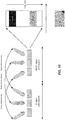
- FIG. 1 illustrates a wireless network for communicating data.
- the communication system 100 includes, for example, user equipment 110A-110C, radio access networks (RANs) 120A-120B, a core network 130, a public switched telephone network (PSTN) 140, the Internet 150, and other networks 160. Additional or alternative networks include private and public data-packet networks including corporate intranets. While certain numbers of these components or elements are shown in the figure, any number of these components or elements may be included in the system 100.
- the wireless network may be a fifth generation (5G) network including at least one 5G base station which employs orthogonal frequency-division multiplexing (OFDM) and/or non-OFDM and a transmission time interval (TTI) shorter than 1 ms (e.g. 100 or 200 microseconds), to communicate with the communication devices.
- 5G fifth generation
- a base station may also be used to refer any of the eNB and the 5G BS (gNB).
- the network may further include a network server for processing information received from the communication devices via the at least one eNB or gNB.
- System 100 enables multiple wireless users to transmit and receive data and other content.
- the system 100 may implement one or more channel access methods, such as but not limited to code division multiple access (CDMA), time division multiple access (TDMA), frequency division multiple access (FDMA), orthogonal FDMA (OFDMA), or single-carrier FDMA (SC-FDMA).
- CDMA code division multiple access
- TDMA time division multiple access
- FDMA frequency division multiple access
- OFDMA orthogonal FDMA
- SC-FDMA single-carrier FDMA
- the user equipment (UE) 110A-110C are configured to operate and/or communicate in the system 100.
- the user equipment 110A-110C are configured to transmit and/or receive wireless signals or wired signals.
- Each user equipment 110A-110C represents any suitable end user device and may include such devices (or may be referred to) as a user equipment/device, wireless transmit/receive unit (WTRU), mobile station, fixed or mobile subscriber unit, pager, cellular telephone, personal digital assistant (PDA), smartphone, laptop, computer, touchpad, wireless sensor, or consumer electronics device.
- WTRU wireless transmit/receive unit
- PDA personal digital assistant
- smartphone laptop, computer, touchpad, wireless sensor, or consumer electronics device.
- the RANs 120A-120B include one or more base stations 170A, 170B (collectively, base stations 170), respectively.
- Each of the base stations 170 is configured to wirelessly interface with one or more of the UEs 110A, 110B, 110C to enable access to the core network 130, the PSTN 140, the Internet 150, and/or the other networks 160.
- the base stations (BSs) 170 may include one or more of several well-known devices, such as a base transceiver station (BTS), a Node-B (NodeB), an evolved NodeB (eNB), a next (fifth) generation (5G) NodeB (gNB), a Home NodeB, a Home eNodeB, a site controller, an access point (AP), or a wireless router, or a server, router, switch, or other processing entity with a wired or wireless network.
- BTS base transceiver station
- NodeB Node-B
- eNB evolved NodeB
- gNB next (fifth) generation
- gNB next (fifth) generation
- gNB next (fifth) generation
- gNB next (fifth) generation
- gNB next (fifth) generation
- gNB next (fifth) generation
- gNB next (fifth) generation
- gNB next (
- the base station 170A forms part of the RAN 120A, which may include other base stations, elements, and/or devices.
- the base station 170B forms part of the RAN 120B, which may include other base stations, elements, and/or devices.
- Each of the base stations 170 operates to transmit and/or receive wireless signals within a particular geographic region or area, sometimes referred to as a "cell.”
- MIMO multiple-input multiple-output
- the base stations 170 communicate with one or more of the user equipment 110A-110C over one or more air interfaces (not shown) using wireless communication links.
- the air interfaces may utilize any suitable radio access technology.
- the system 100 may use multiple channel access functionality, including for example schemes in which the base stations 170 and user equipment 110A-110C are configured to implement the Long Term Evolution wireless communication standard (LTE), LTE Advanced (LTE-A), and/or LTE Broadcast (LTE-B).
- LTE Long Term Evolution wireless communication standard
- LTE-A LTE Advanced
- LTE-B LTE Broadcast
- the base stations 170 and user equipment 110A-110C are configured to implement UMTS, HSPA, or HSPA+ standards and protocols.
- other multiple access schemes and wireless protocols may be utilized.
- the RANs 120A-120B are in communication with the core network 130 to provide the user equipment 110A-110C with voice, data, application, Voice over Internet Protocol (VoIP), or other services.
- VoIP Voice over Internet Protocol
- the RANs 120A-120B and/or the core network 130 may be in direct or indirect communication with one or more other RANs (not shown).
- the core network 130 may also serve as a gateway access for other networks (such as PSTN 140, Internet 150, and other networks 160).
- some or all of the user equipment 110A-110C may include functionality for communicating with different wireless networks over different wireless links using different wireless technologies and/or protocols.
- the RANs 120A-120B may also include millimeter and/or microwave access points (APs).
- the APs may be part of the base stations 170 or may be located remote from the base stations 170.
- the APs may include, but are not limited to, a connection point (a mmW CP) or a base station 170 capable of mmW communication (e.g., a mmW base station).
- the mmW APs may transmit and receive signals in a frequency range, for example, from 6 GHz to 100 GHz, but are not required to operate throughout this range.
- the term base station is used to refer to a base station and/or a wireless access point.
- FIG. 1 illustrates one example of a communication system
- the communication system 100 could include any number of user equipment, base stations, networks, or other components in any suitable configuration.
- user equipment may refer to any type of wireless device communicating with a radio network node in a cellular or mobile communication system.
- Non-limiting examples of user equipment are a target device, device-to-device (D2D) user equipment, machine type user equipment or user equipment capable of machine-to-machine (M2M) communication, laptops, PDA, iPad, Tablet, mobile terminals, smart phones, laptop embedded equipped (LEE), laptop mounted equipment (LME) and USB dongles.
- D2D device-to-device
- M2M machine type user equipment or user equipment capable of machine-to-machine
- laptops PDA, iPad, Tablet
- smart phones laptop embedded equipped (LEE), laptop mounted equipment (LME) and USB dongles.
- LEE laptop embedded equipped
- LME laptop mounted equipment
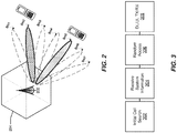
- FIG. 2 illustrates a base station with transmitting and receiving beams according to an example embodiment.
- the base station 202 manages a cell 204 divided into one or more sectors as its service coverage area and forms multiple transmit/receive (Tx/Rx) beams BM1 - BM7 using beamforming schemes, such as digital beamforming (e.g., Transmit (Tx) pre-Inverse Fast Fourier Transform (pre-IFFT) beamforming/Receive (Rx) post-Fast Fourier Transform (post-FFT) beamforming), analog beamforming (e.g., Tx post-IFFT beamforming/Rx pre-FFT beamforming), or a combination thereof.
- the base station 202 transmits the beamformed signals by sweeping them simultaneously or successively, for example, beginning with beam BM1 and ending with BM7.
- UE User equipment
- UE such as user equipment 110A - 110C ( FIG. 1 ) located within the cell of the base station 202 may be configured to receive signals omni-directionally without supporting Rx beamforming, receive signals while supporting Rx beamforming by using one beamforming pattern each time, or receive signals while supporting Rx beamforming by simultaneously using a plurality of beamforming patterns in different directions.
- the user equipment 110A - 110C measures the channel quality of a reference signal (RS) in each transmission beam and reports the measurements to the base station 202.
- the station 202 selects the best beam for the user equipment 110A - 110C from among a plurality of Tx beams. If the user equipment 110A - 110C is configured to support Rx beamforming, the user equipment 110A - 110C measures the channel qualities of multiple Tx beams received from the base station 202 for each reception beam pattern and reports a total or some high-ranked measurements of all Tx-Rx beam pairs to the base station 202.
- the base station 202 may allocate an appropriate Tx beam to the user equipment 110A - 110C.
- the base station 202 may select a beam, taking into account diversity transmission through repeated transmission or simultaneous transmission.
- FIG. 3 illustrates physical channels and transmitting signals on the physical channels in accordance with FIG. 2 .
- user equipment 110A - 110C FIG. 1
- the user equipment performs an initial cell search 302.
- the initial cell search 302 involves acquisition of synchronization to a base station, such as gNB 202.
- the user equipment synchronizes its timing to the gNB and acquires a cell Identifier (ID) and other information by receiving a Primary Synchronization Channel (P-SCH) and a Secondary Synchronization Channel (S-SCH) from the gNB 202.
- ID Cell Identifier
- P-SCH Primary Synchronization Channel
- S-SCH Secondary Synchronization Channel
- the user equipment may acquire information broadcast in the cell by receiving a Physical Broadcast Channel (PBCH) from the gNB 202.
- PBCH Physical Broadcast Channel
- the user equipment may monitor a downlink (DL) channel state by receiving a downlink reference Signal (DL RS).
- DL RS downlink reference Signal
- the user equipment 110A - 110C may acquire detailed system information at 304 by receiving a Physical Downlink Control Channel (PDCCH) and receiving a Physical Downlink Shared Channel (PDSCH) based on information included in the PDCCH.
- PDCH Physical Downlink Control Channel
- PDSCH Physical Downlink Shared Channel
- the user equipment 110A - 110C may perform a random access procedure at 306 with the gNB 202. During the random access procedure 306,
- the user equipment 110A - 110C may receive a PDCCH and/or a PDSCH from the gNB 202 and transmit a Physical Uplink Shared Channel (PUSCH) and/or a PUCCH to the gNB 202, which is a general DL and UL signal transmission procedure at 308.
- the user equipment 110A - 110C receives Downlink Control Information (DCI) on a PDCCH.
- the DCI includes, for example, control information such as resource allocation information for the user equipment 110A - 110C.
- Control information that the user equipment 110A - 110C transmits to the gNB 202 on the uplink (UL) channel or receives from the gNB 202 on the DL channel includes a DL/UL ACKnowledgment/Negative ACKnowledgment (ACK/NACK) signal, a Channel Quality Indicator (CQI), a Precoding Matrix Index (PMI), a Rank Indicator (RI), etc.
- the control information such as a CQI, a PMI, an RI, etc., may be transmitted on a PUSCH and/or a PUCCH.
- FIG. 4 illustrates an example of identifying a new beam when a beam failure is detected.
- a gNB has transmit beams 1tx - 4tx aligned with reference signal resources 1 - 4 and receive beams 1rx - 4rx aligned with beam failure random access control channel (BRACH) resources 1 - 4.
- BRACH beam failure random access control channel
- a BRACH denotes a non-contention based channel that is based on a physical random access channel (PRACH)-like (that is, the physical layer channel structure for beam failure report may be different from PRACH) for a beam failure report (the resources for a beam failure are non-contention based- i.e., dedicated).
- PRACH physical random access channel
- the UE 110 is responsible for regularly and periodically monitoring reference signals RSs for beam failure detection to determine whether a beam failure has been detected. For example, the UE 110 measures reception quality of the reference signals RSs for beam failure detection, in this case the reference signals for beam failure detection are the Channel State Information-Reference Signals (CSI-RSs), transmitted from the respective antenna ports in the base stations.
- CSI-RSs Channel State Information-Reference Signals
- the reference signal for beam failure detection transmitted in a beam is not limited to the CSI-RS and may be a PSS (Primary Synchronization Signal), a SSS (Secondary Synchronization Signal), an Enhanced SS, a Discovery signal, a DM-RS (Data Demodulation-Reference Signal) or the like.
- a synchronization signal (SS)-block within the serving cell may be monitored to determine whether a beam failure has been detected.
- SS synchronization signal
- a new candidate beam is identified by the UE 110 by monitoring the reference signal for new beam identification and selecting a beam 1tx - 4tx having good reception quality based on the measured reception quality.
- the reference signal for new beam identification is a CSI-RS.
- the reference signal for new beam identification is a SS block.
- beam identification includes the UE 110 monitoring each of the beam resources (periodic CSI-RS).
- beam identification includes the UE 110 monitoring the beam resources (periodic CSI-RS) and SS resources (blocks) within the serving cell (not shown).
- the UE 110 sends a beam failure recovery request (BFRR) transmission to the base station (such as gNB 202).
- the gNB may configure each UE 110 with unique BRACH preamble(s) within a BRACH region before the UE 110 transmits the BFRR. That is, the gNB may schedule a channel to report beam failure (i.e. the BRACH) and inform the UE 110. Scheduling a BRACH by the gNB 202 is discussed further below.
- the UE 110 in the case of a beam recovery, may then use the BRACH preamble(s) to send the BFRR.
- the gNB may send out multiple SSs in a one or more resources with different beamforming of SSs on different resources. That is, the gNB 202 may send out multiple resources using different beams within different time frames, as depicted in FIG. 4 .
- the gNB 202 may schedule multiple BRACH resources in the time domain.
- the gNB 202 may signal a fixed relationship between a BRACH resource and an SS resource.
- each of the SS resources (SS resources 1 - 4) have a corresponding Rx beamforming of each of the BRACH resources (BRACH resources 1 - 4), such that a one-to-one association exists (e.g., with reference to the figure, the Tx beam of SS 1 resource holds a beam correspondence relationship with the Rx beam of the BRACH resource 1).
- a Tx beam of a first resource and an Rx beam of a second resource from a gNB hold beam correspondence if (1) a Tx beam of a first resource covers a similar area with an Rx beam of a second resource, or (2) the gNB indicates a spatial quasi co-located (SQCL'ed) relationship between a Tx beam of a first resource and an Rx beam of a second resource.
- SQCL'ed spatial quasi co-located
- SS resources are used as reference signals for new beam identification, and there are four (4) SS resources and four (4) BRACH resources, where each of the Tx beams 1tx - 4tx for the SS resources and each of Rx beams 1rx - 4rx for the BRACH resources 1 - 4 respectively hold beam correspondence.
- the disclosed embodiment is non-limiting and that any number of configurations of UEs, base stations, Tx beams, Rx beams, SS resources, CSI-RS resources and BRACH resources may be employed.
- the UE 110 when a UE 110 measures the SS resources 1 - 4, the UE 110 identifies the SS resource 3 as having the highest received signal quality.
- the received signal quality can be measured in various ways such as reference signal received power (RSRP) (RSRP may be measured using conventional techniques), or signal-to-noise ratio of the received reference signal).
- RSRP reference signal received power
- the gNB 202 receives the preamble with the highest received power on BRACH resource 3, which was identified by UE 110 as having the highest RSRP.
- the UE 110 transmits a previously assigned BRACH preamble to the BRACH resource corresponding to the SS resource that the UE 110 has identified as having the highest received signal quality.
- the gNB 202 receives the BRACH preamble from UE 110 only on BRACH resource 3.
- FIG. 5 illustrates an example of BRACH resource allocation in accordance with the description of FIG. 4 .
- BRACH supports use of a non-contention based channel, where each UE 110 uses a dedicated BRACH preamble.
- BRACH uses the current PRACH structure, there are 64 BRACH preambles supported in each BRACH resource (BRACH#1 - BRACH#4).
- BRACH#1 - BRACH#4 there are 64 BRACH preambles supported in each BRACH resource.
- a single base station's e.g., a gNB's 202
- BRACH resource When one BRACH resource is not sufficient to handle the UEs 110 in the coverage area, more than one BRACH resource needs to be allocated for each beam direction. Furthermore, if more than one BRACH preamble is assigned for each UE 110, the number of UEs 110 supported in each BRACH resource becomes even smaller. For example, if SS beam#1 includes two CSI-RS signals, then the gNB 202 will allocate two preambles to the SS beam#1 for each UE 110-one for each CSI-RS signal in the SS beam. Accordingly, where 'N' CSI-RS beams are included in each SS beam, a single BRACH resource for each beam can support up to 64/N UEs (assuming the current PRACH structure is being utilized). This results in the resources not being used efficiently, even though more than one BRACH resource for each beam is allocated, since the probability of a beam failure occurring is low.
- a gNB's 202 transmit (Tx) beam for each of the SS resources SS#1 - SS#4 and gNB's 202 receive (Rx) beam for each of the BRACH resources (Beam#1 - Beam#4) respectively have identical beam patterns such that beam correspondence holds between them.
- Beam correspondence generally refers to a downlink (DL) beam and an uplink (UL) beam being linked.
- the transmit beam for SS#3 holds beam correspondence with (is linked with) the receive beam for BRACH resource (BRACH#3).
- the SS resources (SS#1 - SS#4) are used as a beam failure detection reference signal (RS) and for identification of a new candidate beam RS.
- the UE 110 is currently using Beam#3 and the gNB 202 assigns BRACH preamble #5 to the UE 110 for a BFRR transmission, as illustrated.
- the UE 110 While a link exists between the UE 110 and the gNB 202, the UE 110 measures the beam failure detection RS (SS resources) to detect when a beam failure occurs.
- the UE 110 determines that a beam failure has occurred, the UE 110 identifies the new candidate beam. Identification of a new candidate beam may be determined, for example, by selecting one of the beams (not including the failed beam) with the highest quality, as determined by measuring the new beam identification RS (SS resources).
- the UE's 110 new candidate beam can be one of Beam#1, Beam#2 and Beam#4. Any one of these beams may be selected as the new candidate beam based on the measured quality of the each beam. In this case, Beam#3 may not be used as the new candidate beam since Beam#3 is the beam (old beam) on which the beam failure occurred.
- the UE 110 sends BRACH preamble #5 (previously assigned by the gNB 202) on a BRACH resource that corresponds to the new candidate beam. For example, if the UE's 110 new candidate beam is k, the UE 110 sends the BRACH preamble #5 at the k th BRACH resource. However, since Beam#3 may not be chosen as the new candidate beam (as it has failed), BRACH#3 will not be utilized. Therefore, the BRACH preamble (in this case BRACH preamble #5) corresponding to the failed beam (in this case Beam#3) remains unused and is wasted.
- BRACH preamble #5 previously assigned by the gNB 202
- the gNB 202 assigns a group of resources (preambles) to a UE 110 for transmission of the BFRR within the BRACH resources, where the group of resources excludes resources that correspond to beam(s) that the UE 110 is currently using (namely, the old beam).
- FIGS. 6A and 6B illustrate an example of resource allocation using synchronization signal based identification.
- the procedures are implemented by one of the base station and/or user equipment.
- the procedure may be implemented by any component or device disclosed in any one or more of the figures, and that the disclosed embodiments are non-limiting.
- SS resources (SS#1 - SS#4) are used for beam failure detection and as a new candidate beam identification RS.
- the gNB 202 transmits multiple SS resources (SS#1 - SS#4), where each of the SS resources have a different beam direction (indicated by the various patterns).
- the gNB 202 also assigns multiple BRACH resources (BRACH#1 - BRACH#4) such that the transmit beamforming of each SS resource, and the receive beamforming of each BRACH resource, hold beam correspondence.
- SS resource SS#1 holds beam correspondence with BRACH resource BRACH#1
- SS resource SS#2 holds beam correspondence with BRACH resource BRACH#2, etc.
- the UE 110 measures SS resources to identify an SS resource (SS_old) with the best signal quality.
- the best signal quality may be, but is not limited to, a beam with the strongest received signal power (RSRP), a beam with the highest signal-to-noise ratio (RSRQ), a beam with the strongest received signal power averaged in time, a beam with the highest signal-to-noise ratio averaged in time, etc.
- the identified SS resource (SS_old) with the best signal quality is used as the current beam.
- the gNB 202 assigns the UE 110 a BRACH preamble for each BRACH resource, except the BRACH resource that holds beam correspondence with the current beam (SS_old).
- the BRACH preamble assigned to the UE 110 on a different BRACH resource does not need to be the same.
- the UE 110 When the UE 110 identifies a beam failure, another one of the SS resources (SS_new) is identified as the new candidate beam. That is, the UE 110 determines the new candidate beam to replace the failed beam. For example, the SS resource (except for SS_old) with the best signal quality will be identified as the new candidate beam.
- the UE 110 transmits the BRACH preamble that is assigned for the UE 110 to the BRACH resource that holds beam correspondence with the newly identified SS resource (SS_new).
- the gNB 202 receives the BRACH preamble at the BRACH resource, and the gNB 202 identifies the UE's 110 new candidate beam as SS_new.
- the gNB 202 manages BRACH preamble allocation separately for each BRACH resource. For example, when the gNB 202 allocates BRACH preambles for a UE 110, the gNB 202 does not allocate a BRACH preamble for the UE 110 on the BRACH resource (BRACH_old) that holds beam correspondence with the UE's 110 current SS beam (SS_old). Rather, for a BRACH resource other than the BRACH_old, the gNB 202 assigns a BRACH preamble from the BRACH preambles that are not used in the BRACH resource.
- BRACH_old BRACH resource
- SS_old current SS beam
- the gNB 202 when the gNB 202 assigns a BRACH preamble(s) to a UE 110, the gNB 202 separately indicates the BRACH preamble(s) for each BRACH resource. For example, when a gNB 202 assigns the same BRACH preamble for all four BRACH resources to a UE 110, the gNB 202 repeats such indication each time (four times in this case) for each BRACH resource.
- SS#1 - SS#4 there are four SS resources (SS#1 - SS#4) and four BRACH resources (BRACH#1 - BRACH#4), where the i th SS#i and the i th BRACH#i hold beam correspondence (1 ⁇ i ⁇ 4).
- UEs 110 e.g., UE1 - UE4
- UE1 - UE4 are covered by the gNB 202, where each UE 110 is located in an area covered by a different SS resource (SS#1 - SS#4).
- the gNB 202 allocates BRACH preambles for the four UEs 110 (UE1 - UE4) according to the table illustrated in FIG. 6B .
- a BRACH preamble is not assigned for the BRACH resource that corresponds to the SS resource of the UE 110 currently in use.
- the SS resource for UE 110 (UE1) is SS#1, which holds beam correspondence with BRACH resource BRACH#1; the SS resource for UE 110 (UE2) is SS#2, which holds beam correspondence with BRACH resource BRACH#2, etc.
- UE 110 (UE1) identifies a beam failure has occurred and suggests a new candidate beam as SS#2.
- the UE 110 (UE1) transmits BRACH preamble#1 at the second BRACH resource (BRACH#2).
- the gNB 202 receives BRACH preamble#1 at BRACH#2 and identifies that UE 110 (UE1) has a beam failure and with a new candidate beam as SS#2.
- FIG. 7 illustrates an example capacity comparison between conventional resource assignment and resource assignment according to embodiments of the disclosure.
- the BRACH resources can support up to N UEs, as noted above.
- the BRACH resources can support up to N * (K/(K-1)) UEs (when UEs are evenly spread out in areas covered by different SS beams), where there are N BRACH preambles available for each BRACH resource, and there are K BRACH resources with different beams.
- the number of UEs that are supported is restricted by a BRACH resource such that the maximum number of BRACH preambles are allocated.
- FIGS. 8A and 8B illustrate an example assignment of more than one resource to a UE for beam failure transmission.
- the procedures are implemented by one of the base station and/or user equipment.
- the procedure may be implemented by any component or device disclosed in any one or more of the figures, and that the disclosed embodiments are non-limiting.
- a UE 110 (e.g., UE1 - UE4) has more than one SS resource (e.g., Beam#1 and Beam#2) currently in use.
- the gNB 202 does not allocate a BRACH preamble for the UE 110 on BRACH resources that hold beam correspondence with SS resources currently in use by the UE 110, as explained in the example that follows.
- UEs 110 e.g., UE1 - UE4 are covered by the gNB 202, where each UE 110 has two SS resources (e.g., two of SS#1 - SS#4) being used.
- UE 110 UE1
- Beam#1 and Beam #2 e.g., UE#i has a current beam that is SS#[mod(i-1,4)+1], and SS#[mod(i,4)+1].
- the gNB 202 allocates BRACH preambles for the four UEs 110 (e.g., UE1 - UE4) according to the table illustrated in FIG. 8B .
- two BRACH preambles are not assigned for the BRACH resources that correspond to the two SS resources of the UE 110 currently in use.
- the SS resources in use by UE 110 (UE1) are SS#1 and SS#2, which hold beam correspondence with BRACH resources BRACH#1 and BRACH#2.
- UE1 the SS resources in use by UE 110
- UE1 the SS resources in use by UE 110 (UE1) are SS#1 and SS#2, which hold beam correspondence with BRACH resources BRACH#1 and BRACH#2.
- UE 110 identifies a beam failure has occurred and suggests a new candidate beam as SS#4.
- UE 110 transmits BRACH preamble#2 at the fourth BRACH resource (BRACH#4), and the gNB 202 receives BRACH preamble#2 at BRACH#4 and identifies that UE 110 (UE1) has a beam failure and that the new candidate beam is SS#4.
- BRACH#4 fourth BRACH resource
- FIGS. 9A and 9B illustrate an example of resource allocation using reference signal based identification.
- the procedures are implemented by one of the base station and/or user equipment.
- the procedure may be implemented by any component or device disclosed in any one or more of the figures, and that the disclosed embodiments are non-limiting.
- a reference signal RS (such as a CSI-RS) is used for beam failure detection and as a new candidate beam identification RS.
- FIG. 9A illustrates the assignment of unique resources in Frequency Division Multiplexing (FDM)
- FIG. 9B illustrates the assignment of unique resources in Time Division Multiplexing (TDM).
- the different resources can be, for example, a different BRACH preamble, a unique BRACH preamble assigned in different time TDM ( FIG. 9B ), a unique BRACH preamble assigned in different frequency resource FDM ( FIG. 9A ), or a combination of above cases.
- each BRACH preamble depicted is a resource.
- the first column of BRACH #1 has four resources, each represented by an individual BRACH block.
- the gNB 202 assigns SS resources to the UE 110 such that one assigned SS resource corresponds to more than one CSI-RS beam.
- the gNB 202 transmits multiple SS resources, where each of the SS resources has a different beam direction.
- the gNB 202 also transmits multiple CSI-RS resources, where each of the CSI-RS resources has a different beam direction and SS resources and CSI-RS resources have a relationship where the spatial domain of each SS resource covers the spatial domain of one or more CSI-RS resources. That is, more than one CSI-RS beam may be assigned to an SS beam (not shown).
- the assignment of the multiple BRACH resources by the gNB 202 to the UE 110 is such that transmit beamforming (of each SS resource) and the receive beamforming (of each BRACH resource) hold beam correspondence.
- the UE 110 may then identify the CSI-RS resources (CRI_old) with the best signal quality by measuring the CSI-RS resources.
- the CRI_old is then used as the current CSI-RS resource(s).
- the CRI stands for the CSI-RS Resource Indicator (CRI).
- the SS resources may be categorized into two groups: (1) a first group of SS resources that do not cover the spatial domain of current CSI-RS resources (CRI_old), and (2) a second group of SS resources that cover the spatial domain of at least one of current CSI-RS resources (CRI_old).
- the gNB 202 assigns the UE 110 one or more resources within the BRACH resource, wherein the number of resources corresponds to the number of CSI-RS resources within the SS resource.
- the gNB 202 assigns the UE 110 one or more resources within the BRACH resource, wherein the number resources corresponds to the number of CSI-RS resources within the SS resource that are not any of current CSI-RS resource(s) (CRI_old).
- the resources assigned to the UE 110 on different BRACH resource can be different.
- the UE 110 may then identify when a beam failure occurs by measuring the CSI-RS resources and identify another CSI-RS resource (CRI_new) as a new candidate beam.
- CRI_new another CSI-RS resource
- new candidate beams may be selected based on the best signal quality amongst the available beams.
- the UE 110 transmits the resource (preamble) that has been assigned to the UE 110 for the CRI_new at the BRACH resource.
- the gNB 202 receives the resource at the BRACH resource and identifies the UE's 110 new candidate beam as CRI_new.
- FIG. 9C illustrates allocation of BRACH preambles as resources for each user equipment when employing reference beam identification.
- four SS resources and four BRACH resources exist, where SS#i and BRACH#i hold beam correspondence (1 ⁇ i ⁇ 4); each SS resource (SS#i) covers two CSI-RS resources (More than one CSI-RS beam may be covered by a single SS beam since the CSI-RS beam is narrower than the SS beam.
- a transmit beam at the gNB for SS#i covers a transmit beam for the (2(i-1)+1) th and (2(i-1)+2) th CSI-RS resources (the two covered resources).
- SS#1 covers CRI#1 and 2
- SS#2 covers CRI#3 and 4
- SS#3 covers CRI#5 and 6
- SS#4 covers CRI#7 and 8
- UEs 110 there are eight UEs 110 (UE1 - UE8), in which there are four BRACH resources (BRACH#1 - BRACH#4) having beam correspondence with four SS resources (SS#1 - SS#4), where each SS resource covers two CSI-RS resources.
- UE 110 UE1 has two beams (CRI#1, CR#2) which are covered by SS#1, where SS#1 holds beam correspondence with BRACH#1 and the current UE 110 (UE1) beam is CRI#1.
- the gNB 202 assigns a BRACH preamble (preamble#1) as a resource within BRACH#1 for UE 110 (UE1), no BRACH preamble is assigned to CRI#1 (since no preamble is assigned on the current beam) and the BRACH preamble (preamble#1) is assigned to CRI#2. Otherwise, for UE 110 (UE1), the gNB 202 assigns two BRACH preambles as resources within a BRACH#i (BRACH#2, BRACH#3, BRACH#4) wherein each BRACH preamble is assigned to each CRI within the BRACH#i.
- the gNB 202 assigns a BRACH preamble (preamble#2) as a resource for CRI#1 within BRACH#1, except for the current beam (in this case, CRI#2). Otherwise, for UE 110 (UE2), the gNB 202 assigns two BRACH preambles as resources within a BRACH#i (BRACH#2, BRACH#3, BRACH#4). The gNB 202 assigns BRACH preambles for each of UEs 110 (UE3 - UE8) using a similar methodology.
- the UE 110 when a UE 110 (UE1) identifies that a beam failure occurs, the UE 110 (UE1) provides a new candidate beam (in this case, CRI#7) to the gNB 202.
- the UE110 (UE1) transmits BRACH preamble#1 at BRACH#4 (since BRACH#4 covers CRI#7), and the gNB 202 receives BRACH preamble#1 at BRACH#4, identifies that a beam failure has occurred for UE 110 (UE1)and identifies the new candidate beam of CRI#7 based on the preamble transmitted by the UE 110 (UE1).
- FIG. 10 illustrates a beam failure recovery report transmission based on a reference signal association.
- a newly identified beam index n includes at least a CSI-RS beam index, e.g., CRI, at the UE 110.
- any set of CSI-RS beams e.g. CRI 1 , ..., CRI n , ..., gNB
- CRI 1 , ..., CRI n , ..., gNB can signal to the UE 110 the QCL relationship between CSI-RS and SS.
- UE 110 can infer the corresponding SS with index m, such that SSm and CRI n is spatially QCLed.
- a single SS signal may hold a spatial QCL relationship with more than one CSI-RS signals. That is, a single SS signal may have a wider beam width than a single CSI-RS signal, as noted above. If ⁇ m is the set of CSI-RS signals (without respect to order) that hold a spatial QCL relationship with SS m . Then, without loss of generality, let CRI n be the i th CSI-RS within the signal set ⁇ m .
- n can be uniquely identified by the pair ⁇ m , i ⁇ , it is clear that in order to for gNB 202 to obtain the newly identified beam index n, it is sufficient for UE 110 to signal the SS index m for which CRI n is spatially QCLed with, as well as the secondary index i of CRI n within the signal set ⁇ m .
- Non-contention based channel based on PRACH which uses a resource orthogonal to resources of other PRACH transmissions, at least for FDM case
- the PRACH resource for initial access is FDM'ed with the BRACH (BFR RACH) resource for BFR (beam failure recover).
- the diagram illustrates an SS region where multiple SS signals (SS#1 - SS#3) are transmitted by the gNB 202 using multiple transmit precoders, as well as a BRACH region where multiple BRACH resources (BRACH#1 - BRACH#3) are allocated together with PRACH resources in a FDM manner while gNB 202 receives using multiple receive precoders/combiners. For each SS signal using a particular transmit precoder, there is a unique BRACH resource using a beam corresponding receiver combiner with a fixed relative time-frequency relation.
- the SS index m (for which CRI n is spatially QCLed) can be signaled in an implicit manner by sending the BFRR on the mth BRACH resource BRACH m which holds a one-to-one mapping relationship with SS m .
- gNB 202 can detect the SS index m.
- the secondary index i of CRI n within the signal set ⁇ m can be signaled separately, using several different methods.
- the secondary index i can be signaled explicitly when the UE 110 has obtained a transmission grant.
- each UE 110 may be assigned multiple unique sequences in advance with each sequence representing one secondary index within the signal set ⁇ m .
- the secondary index i can be signaled to gNB 202 implicitly by selection of a proper sequence at the UE side. By analyzing the preamble sequence being used, gNB 202 can detect the UE 110 identity and the secondary index i.
- each UE 110 may be assigned multiple BRACH sub-resources, on which the preamble sequence may be transmitted, where each BRACH sub-resource represents one secondary index within the signal set ⁇ m .
- the secondary index i can be signaled to gNB 202 implicitly by selection of a proper BRACH resource at the UE side.
- gNB 202 can detect the secondary index i.
- Additional embodiments may include any one of the following aspects: the resource from the group of one or more resources are different BRACH preambles; the resources from the group of one or more resources are a BRACH preamble assigned in different time slots assigned within the BRACH resource; the resources from the group of one or more resources are a BRACH preamble assigned in different frequency blocks assigned within the BRACH resource; the CSI-RS is used as the beam failure detection reference signal; the information on mapping between one and the number of the beam failure detection reference signals within each BRACH resource is predetermined without explicit indication; the k th beam failure detection reference signal is mapped to mod(K, N_R) resource assigned to the UE, wherein K denotes the third number of the beam failure detection reference signals for each BRACH resource, N_R denotes the resources from the group of one or more resources assigned to the UE, and mod(x, y) operator denotes the remainder after division of x by y.
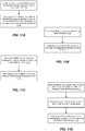
- FIGS. 11A-11D illustrate flow diagrams of assigning resources to user equipment for transmission of a beam failure recovery request.
- the procedures are implemented by one of the base station or user equipment.
- the procedure may be implemented by any component or device disclosed in any one or more of the figures, and that the disclosed embodiments are non-limiting.
- resources are assigned to user equipment 110 for a beam failure recovery by a base station 202.
- a beam failure random access channel (BRACH) resource holding beam correspondence with a synchronization signal (SS) block resource covering the user equipment 110 is identified, and at 1104 the user equipment 110 is assigned a BRACH preamble for each BRACH resource assigned to the user equipment 110, except the BRACH resource holding beam correspondence between the base station's SS block resource covering the user equipment 110.
- BRACH beam failure random access channel
- SS synchronization signal
- the base station 202 transmits the SS block resources to the user equipment 110, where each of the SS block resources has a different beam direction, and for each BRACH resource assigned to the user equipment 110, a corresponding one of the Tx beams of each SS resources and the Tx beam of each BRACH resource hold beam correspondence.
- the base station 202 receives a beam failure recovery request (BFRR) from the user equipment 110, including identification of a different SS block resource as a new candidate beam (which does not include the SS block resource of the current beam), upon detection of a beam failure between the base station and the user equipment 110.
- BFRR beam failure recovery request
- the base station 202 identifies the new candidate beam upon receiving a BRACH preamble assigned for the user equipment 110 at the BRACH resource.
- the base station 202 sets a direction of a receive beam for each of the receive RF-chains in a different direction at the BRACH resource, at 1114.
- the base station 202 determines a received signal strength from each of the receive RF-chain when receiving the one of the resources from a group of the resources, and identifies a user equipment 110 direction based the receive beam direction of the receive RF-chain that has the highest received signal strength at 1118.
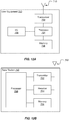
- FIG. 12A illustrates example user equipment that may implement the methods and teachings according to this disclosure.
- the UE 1200 includes at least one processor 1204.
- the processor 1204 implements various processing operations of the UE 1200.
- the processor 1204 may perform signal coding, data processing, power control, input/output processing, or any other functionality enabling the UE 1200 to operate in the system 100 ( FIG. 1 ).
- the processor 1204 may include any suitable processing or computing device configured to perform one or more operations.
- the processor 1204 may include a microprocessor, microcontroller, digital signal processor, field programmable gate array, or application specific integrated circuit.
- the UE 1200 also includes at least one transceiver 1202.
- the transceiver 1202 is configured to modulate data or other content for transmission by at least one antenna 1210.
- the transceiver 1202 is also configured to demodulate data or other content received by the at least one antenna 1210.
- Each transceiver 1202 may include any suitable structure for generating signals for wireless transmission and/or processing signals received wirelessly.
- Each antenna 1210 includes any suitable structure for transmitting and/or receiving wireless signals. It is appreciated that one or multiple transceivers 1202 could be used in the UE 1200, and one or multiple antennas 1210 could be used in the UE 1200.
- a transceiver 1202 may also be implemented using at least one transmitter and at least one separate receiver.
- the UE 1200 further includes one or more input/output devices 1208.
- the input/output devices 1208 facilitate interaction with a user.
- Each input/output device 1208 includes any suitable structure for providing information to or receiving information from a user, such as a speaker, microphone, keypad, keyboard, display, or touch screen.
- the UE 1200 includes at least one memory 1206.
- the memory 1206 stores instructions and data used, generated, or collected by the UE 1200.
- the memory 1206 could store software or firmware instructions executed by the processor(s) 1204 and data used to reduce or eliminate interference in incoming signals.
- Each memory 1206 includes any suitable volatile and/or non-volatile storage and retrieval device(s). Any suitable type of memory may be used, such as random access memory (RAM), read only memory (ROM), hard disk, optical disc, subscriber identity module (SIM) card, memory stick, secure digital (SD) memory card, and the like.
- FIG. 12B illustrates example base station that may implement the methods and teachings according to this disclosure.
- the base station 1250 includes at least one processor 1258, at least one transmitter 1252, at least one receiver 1254, one or more antennas 1260, and at least one memory 1256.
- the processor 1258 implements various processing operations of the base station 1250, such as signal coding, data processing, power control, input/output processing, or any other functionality.
- Each processor 1258 includes any suitable processing or computing device configured to perform one or more operations.
- Each processor 1258 could, for example, include a microprocessor, microcontroller, digital signal processor, field programmable gate array, or application specific integrated circuit.
- Each transmitter 1252 includes any suitable structure for generating signals for wireless transmission to one or more UEs or other devices.
- Each receiver 1254 includes any suitable structure for processing signals received wirelessly from one or more UEs or other devices. Although shown as separate components, at least one transmitter 1252 and at least one receiver 1254 could be combined into a transceiver.
- Each antenna 1260 includes any suitable structure for transmitting and/or receiving wireless signals. While a common antenna 1260 is shown here as being coupled to both the transmitter 1252 and the receiver 1254, one or more antennas 1260 could be coupled to the transmitter(s) 1252, and one or more separate antennas 1260 could be coupled to the receiver(s) 1254.
- Each memory 1256 includes any suitable volatile and/or non-volatile storage and retrieval device(s).
- FIG. 13 is a block diagram of a network device that can be used to implement various embodiments. Specific network devices may utilize all of the components shown, or only a subset of the components, and levels of integration may vary from device to device. Furthermore, the network device 1300 may contain multiple instances of a component, such as multiple processing units, processors, memories, transmitters, receivers, etc.
- the network device 1300 may comprise a processing unit 1301 equipped with one or more input/output devices, such as network interfaces, storage interfaces, and the like.
- the processing unit 1301 may include a central processing unit (CPU) 1310, a memory 1320, a mass storage device 1330, and an I/O interface 1360 connected to a bus 1370.
- the bus 1370 may be one or more of any type of several bus architectures including a memory bus or memory controller, a peripheral bus or the like.
- the CPU 1310 may comprise any type of electronic data processor.
- the memory 1320 may comprise any type of system memory such as static random access memory (SRAM), dynamic random access memory (DRAM), synchronous DRAM (SDRAM), read-only memory (ROM), a combination thereof, or the like.
- the memory 1320 may include ROM for use at boot-up, and DRAM for program and data storage for use while executing programs.
- the memory 1320 is non-transitory.
- the memory 1320 includes an identifying module 1321A, an assigning module 1321B, a transmitting module 1321C, a receiving module 1321D and a setting module 1321E.
- the mass storage device 1330 may comprise any type of storage device configured to store data, programs, and other information and to make the data, programs, and other information accessible via the bus 1370.
- the mass storage device 1330 may comprise, for example, one or more of a solid state drive, hard disk drive, a magnetic disk drive, an optical disk drive, or the like.
- the processing unit 1301 also includes one or more network interfaces 1350, which may comprise wired links, such as an Ethernet cable or the like, and/or wireless links to access nodes or one or more networks 1380.
- the network interface 1350 allows the processing unit 1301 to communicate with remote units via the networks 1380.
- the network interface 1350 may provide wireless communication via one or more transmitters/transmit antennas and one or more receivers/receive antennas.
- the processing unit 1301 is coupled to a local-area network or a wide-area network for data processing and communications with remote devices, such as other processing units, the Internet, remote storage facilities, or the like.
- the computer-readable non-transitory media includes all types of computer readable media, including magnetic storage media, optical storage media, and solid state storage media and specifically excludes signals.
- the software can be installed in and sold with the device. Alternatively the software can be obtained and loaded into the device, including obtaining the software via a disc medium or from any manner of network or distribution system, including, for example, from a server owned by the software creator or from a server not owned but used by the software creator.
- the software can be stored on a server for distribution over the Internet, for example.
- each process associated with the disclosed technology may be performed continuously and by one or more computing devices.
- Each step in a process may be performed by the same or different computing devices as those used in other steps, and each step need not necessarily be performed by a single computing device.
Claims (11)
- Verfahren zum Zuweisen von Ressourcen an Benutzerausrüstung für eine Strahlausfallwiederherstellung durch eine Basisstation, das Folgendes umfasst:Identifizieren einer Ressource für einen Strahlausfall-Direktzugriffskanal (BRACH), die eine Strahlkorrespondenz mit einer Synchronisationssignal-(SS-)Blockressource hält, die die Benutzerausrüstung abdeckt; undZuweisen der Benutzerausrüstung zu einer oder mehreren BRACH-Präambeln für jede BRACH-Ressource, die der Benutzerausrüstung zugewiesen ist, mit Ausnahme der BRACH-Ressource, die eine Strahlkorrespondenz mit der SS-Blockressource hält, die die Benutzerausrüstung abdeckt.
- Verfahren nach Anspruch 1, das ferner Folgendes umfasst:
Übertragen einer oder mehrerer der SS-Blockressourcen, wobei jede der SS-Blockressourcen eine andere Strahlrichtung aufweist. - Verfahren nach Anspruch 2, wobei die BRACH-Ressource N * (K/(K-1)) Benutzerausrüstungen unterstützt, wobei N eine Anzahl von Benutzerausrüstungen und K eine Anzahl von BRACH-Ressourcen mit unterschiedlichen Strahlen ist.
- Verfahren nach Anspruch 1, wobei, wenn die Benutzerausrüstung mehr als eine SS-Blockressource im Gebrauch hat, die Basisstation keine BRACH-Präambel für die Benutzerausrüstung auf den BRACH-Ressourcen zuweist, die eine Strahlkorrespondenz mit den verwendeten SS-Blockressourcen halten.
- Verfahren nach Anspruch 1, das ferner Folgendes umfasst:Empfangen einer Strahlausfallwiederherstellungsanforderung (BFRR) von der Benutzerausrüstung, einschließlich der Identifizierung einer anderen SS-Blockressource als neuer Kandidatenstrahl, bei Detektion eines Strahlausfalls zwischen der Basisstation und der Benutzerausrüstung; undIdentifizieren des neuen Kandidatenstrahls bei Empfangen einer BRACH-Präambel, die für die Benutzerausrüstung an der BRACH-Ressource zugewiesen ist.
- Gerät zum Zuweisen von Ressourcen an Benutzerausrüstung für eine Strahlausfallwiederherstellung durch eine Basisstation, das Folgendes umfasst:einen nichtflüchtigen Speicher, der Anweisungen umfasst; undeinen oder mehrere Prozessoren in Kommunikation mit dem Speicher, wobei der eine oder die mehreren Prozessoren die Anweisungen zu Folgendem ausführen:Identifizieren einer Ressource für einen Strahlausfall-Direktzugriffskanal (BRACH), die eine Strahlkorrespondenz mit einer Synchronisationssignal-(SS-)Blockressource hält, die die Benutzerausrüstung abdeckt; undZuweisen der Benutzerausrüstung zu einer oder mehreren BRACH-Präambeln für jede BRACH-Ressource, die der Benutzerausrüstung zugewiesen ist, mit Ausnahme der BRACH-Ressource, die eine Strahlkorrespondenz mit der SS-Blockressource hält, die die Benutzerausrüstung abdeckt.
- Gerät nach Anspruch 6, wobei der eine oder die mehreren Prozessoren ferner die Anweisungen zu Folgendem ausführen:
Übertragen einer oder mehrerer der SS-Blockressourcen, wobei jede der SS-Blockressourcen eine andere Strahlrichtung aufweist. - Gerät nach Anspruch 6, wobei die BRACH-Ressource N * (K/(K-1)) Benutzerausrüstungen unterstützt, wobei N eine Anzahl von Benutzerausrüstungen und K eine Anzahl von BRACH-Ressourcen mit unterschiedlichen Strahlen ist.
- Gerät nach Anspruch 6, wobei, wenn die Benutzerausrüstung mehr als eine SS-Blockressource im Gebrauch hat, die Basisstation keine BRACH-Präambel für die Benutzerausrüstung auf den BRACH-Ressourcen zuweist, die eine Strahlkorrespondenz mit den verwendeten SS-Blockressourcen halten.
- Gerät nach Anspruch 6, wobei der eine oder die mehreren Prozessoren ferner die Anweisungen zu Folgendem ausführen:Empfangen einer Strahlausfallwiederherstellungsanforderung (BFRR) von der Benutzerausrüstung, einschließlich der Identifizierung einer anderen SS-Blockressource als neuer Kandidatenstrahl, bei Detektion eines Strahlausfalls zwischen der Basisstation und der Benutzerausrüstung; undIdentifizieren des neuen Kandidatenstrahls bei Empfangen einer BRACH-Präambel, die für die Benutzerausrüstung an der BRACH-Ressource zugewiesen ist.
- Computerprogramm mit einem Programmcode zum Durchführen des Verfahrens nach den Ansprüchen 1-5, wenn das Computerprogramm auf einem Computer ausgeführt wird.
Applications Claiming Priority (3)
| Application Number | Priority Date | Filing Date | Title |
|---|---|---|---|
| US201762555490P | 2017-09-07 | 2017-09-07 | |
| US15/796,449 US10374683B2 (en) | 2017-09-07 | 2017-10-27 | Apparatus and method for beam failure recovery |
| PCT/CN2018/100216 WO2019047671A1 (en) | 2017-09-07 | 2018-08-13 | APPARATUS AND METHOD FOR BEAM FAILURE RECOVERY |
Publications (3)
| Publication Number | Publication Date |
|---|---|
| EP3659379A1 EP3659379A1 (de) | 2020-06-03 |
| EP3659379A4 EP3659379A4 (de) | 2020-10-21 |
| EP3659379B1 true EP3659379B1 (de) | 2021-10-06 |
Family
ID=65517711
Family Applications (1)
| Application Number | Title | Priority Date | Filing Date |
|---|---|---|---|
| EP18854993.5A Active EP3659379B1 (de) | 2017-09-07 | 2018-08-13 | Vorrichung und verfahren zur strahlausfallwiederherstellung |
Country Status (4)
| Country | Link |
|---|---|
| US (3) | US10374683B2 (de) |
| EP (1) | EP3659379B1 (de) |
| CN (1) | CN111052840B (de) |
| WO (1) | WO2019047671A1 (de) |
Families Citing this family (24)
| Publication number | Priority date | Publication date | Assignee | Title |
|---|---|---|---|---|
| CN109392123A (zh) * | 2017-08-10 | 2019-02-26 | 株式会社Ntt都科摩 | 波束选择方法、基站和用户设备 |
| US10374683B2 (en) | 2017-09-07 | 2019-08-06 | Futurewei Technologies, Inc. | Apparatus and method for beam failure recovery |
| EP3713340A4 (de) * | 2017-11-17 | 2021-08-18 | Lg Electronics Inc. | Verfahren zur durchführung einer strahlausfallwiederherstellung in einem drahtlosen kommunikationssystem und vorrichtung dafür |
| US10880927B2 (en) * | 2017-11-17 | 2020-12-29 | Qualcomm Incorporated | Mapping rules between synchronization signal blocks and random access channel resources |
| CN113747585A (zh) * | 2017-11-27 | 2021-12-03 | 华为技术有限公司 | 一种链路恢复方法、终端设备及网络设备 |
| US10638482B2 (en) * | 2017-12-15 | 2020-04-28 | Qualcomm Incorporated | Methods and apparatuses for dynamic beam pair determination |
| KR102439425B1 (ko) * | 2017-12-21 | 2022-09-05 | 삼성전자 주식회사 | 무선 셀룰라 통신 시스템에서 안테나 빔 추적 방법 및 장치 |
| CN111567119B (zh) * | 2017-12-22 | 2024-02-13 | 中兴通讯股份有限公司 | 用于执行波束故障恢复的方法和无线通信设备 |
| EP3735019A4 (de) * | 2017-12-27 | 2021-08-04 | NTT DoCoMo, Inc. | Benutzerendgerät und funkkommunikationsverfahren |
| US10880896B2 (en) * | 2018-05-31 | 2020-12-29 | Qualcomm Incorporated | Identifying beams of interest for position estimation |
| US11012137B2 (en) | 2018-08-09 | 2021-05-18 | Comcast Cable Communications, Llc | Resource management for beam failure recovery procedures |
| CN110891301B (zh) * | 2018-09-10 | 2021-08-24 | 维沃移动通信有限公司 | 一种信道测量方法、终端设备和网络侧设备 |
| US11265949B2 (en) * | 2018-10-08 | 2022-03-01 | Qualcomm Incorporated | Fast secondary cell recovery for ultra-reliable low-latency communication |
| US20220271817A1 (en) * | 2019-03-11 | 2022-08-25 | Lg Electronics Inc. | Method for transmitting beam information by user equipment in wireless communication system, and user equipment and base station supporting same |
| EP3949576A4 (de) * | 2019-03-28 | 2022-04-20 | ZTE Corporation | Verfahren zur datenübertragung |
| WO2020220372A1 (en) * | 2019-05-02 | 2020-11-05 | Qualcomm Incorporated | Beam failure recovery using two-step contention free random access channel procedure |
| CN112512071A (zh) * | 2019-09-16 | 2021-03-16 | 中国移动通信有限公司研究院 | 一种波束恢复的方法和基站、终端 |
| US11601925B2 (en) * | 2020-04-17 | 2023-03-07 | Qualcomm Incorporated | Quasi co-location relationship reporting |
| US20210367736A1 (en) * | 2020-05-21 | 2021-11-25 | Qualcomm Incorporated | Positioning measurement reporting |
| US20220045823A1 (en) * | 2020-08-07 | 2022-02-10 | Qualcomm Incorporated | User equipment (ue) recommended sounding reference signal (srs) resource index (sri) |
| US20220132517A1 (en) * | 2020-10-23 | 2022-04-28 | Samsung Electronics Co., Ltd. | Method and apparatus for partial beam failure recovery in a wireless communications system |
| EP4214851A1 (de) | 2020-12-15 | 2023-07-26 | Ofinno Technologies, LLC | Standard-common-beam-mechanismus für ein mehrstrahlszenario |
| US20220311497A1 (en) * | 2021-03-29 | 2022-09-29 | Qualcomm Incorporated | Method for indicating a beam correspondence failure |
| CN114785393B (zh) * | 2022-06-21 | 2022-09-02 | 四川太赫兹通信有限公司 | 一种自适应波束宽度确定方法、系统、基站及介质 |
Family Cites Families (40)
| Publication number | Priority date | Publication date | Assignee | Title |
|---|---|---|---|---|
| US7177644B2 (en) * | 2003-02-12 | 2007-02-13 | Nortel Networks Limited | Distributed multi-beam wireless system |
| JP4913222B2 (ja) * | 2010-02-12 | 2012-04-11 | シャープ株式会社 | 無線通信システム、移動局装置、無線通信方法および集積回路 |
| KR101839386B1 (ko) | 2011-08-12 | 2018-03-16 | 삼성전자주식회사 | 무선 통신 시스템에서의 적응적 빔포밍 장치 및 방법 |
| KR101995798B1 (ko) * | 2012-07-03 | 2019-07-03 | 삼성전자주식회사 | 빔포밍을 사용하는 통신 시스템의 랜덤 억세스 장치 및 방법 |
| US9900196B2 (en) * | 2014-11-26 | 2018-02-20 | Avago Technologies General Ip (Singapore) Pte. Ltd. | Switching diversity in scalable radio frequency communication system |
| KR101810633B1 (ko) * | 2014-12-19 | 2017-12-19 | 한국전자통신연구원 | 셀룰러 이동통신시스템에서의 시스템 운용 방법 및 장치 |
| EP3998822A1 (de) | 2015-08-11 | 2022-05-18 | Telefonaktiebolaget LM Ericsson (PUBL) | Wiederherstellung nach einem strahlausfall |
| CN106817762B (zh) * | 2015-11-30 | 2020-01-31 | 华为技术有限公司 | 一种随机接入方法和基站以及用户设备 |
| US10575338B2 (en) * | 2016-02-04 | 2020-02-25 | Samsung Electronics Co., Ltd. | Method and apparatus for UE signal transmission in 5G cellular communications |
| US10278160B2 (en) * | 2016-02-26 | 2019-04-30 | Samsung Electronics Co., Ltd. | Apparatus and method for performing random access in beam-formed system |
| JP6525357B2 (ja) * | 2016-02-29 | 2019-06-05 | 三菱電機株式会社 | ビーム送受信方法、基地局、端末、および無線通信システム |
| US10615862B2 (en) * | 2016-04-13 | 2020-04-07 | Qualcomm Incorporated | System and method for beam adjustment request |
| US10367677B2 (en) * | 2016-05-13 | 2019-07-30 | Telefonaktiebolaget Lm Ericsson (Publ) | Network architecture, methods, and devices for a wireless communications network |
| CN114641010B (zh) * | 2016-07-20 | 2024-04-26 | 艾普拉控股有限公司 | 使用波束成形和选择的无线电设备的移动性 |
| WO2018062771A1 (en) * | 2016-09-29 | 2018-04-05 | Samsung Electronics Co., Ltd. | Methods and apparatus for supporting multiple services in wireless communication system |
| US10154514B2 (en) * | 2016-10-18 | 2018-12-11 | Qualcomm Incorporated | Scheduling request transmission for directional beam access |
| US10172071B2 (en) * | 2016-10-21 | 2019-01-01 | Qualcomm Incorporated | Directional synchronization in assisted millimeter wave systems |
| US10284278B2 (en) * | 2016-11-04 | 2019-05-07 | Qualcomm Incorporated | Beam management for various levels of beam correspondence |
| US11140706B2 (en) * | 2017-02-01 | 2021-10-05 | Qualcomm Incorporated | Data transmissions during base station beamsweep |
| US10454755B2 (en) * | 2017-03-22 | 2019-10-22 | Qualcomm Incorporated | Beam failure identification and recovery techniques |
| WO2018174667A1 (en) * | 2017-03-23 | 2018-09-27 | Samsung Electronics Co., Ltd. | Method and apparatus for beam recovery of single/multi-beam pair link (bpl) in multi-beam based system |
| US10602520B2 (en) * | 2017-03-24 | 2020-03-24 | Qualcomm Incorporated | Multi-link control beam switching |
| US10931514B2 (en) * | 2017-03-31 | 2021-02-23 | Futurewei Technologies, Inc. | System and method for communications beam recovery |
| US11134492B2 (en) * | 2017-04-12 | 2021-09-28 | Samsung Electronics Co., Ltd. | Method and apparatus for beam recovery in next generation wireless systems |
| US10841062B2 (en) * | 2017-05-04 | 2020-11-17 | Qualcomm Incorporated | Sequence for reference signals during beam refinement |
| EP4013122A1 (de) * | 2017-05-04 | 2022-06-15 | Beijing Xiaomi Mobile Software Co., Ltd. | Auf strahlung basierende messkonfiguration |
| US20180332625A1 (en) * | 2017-05-12 | 2018-11-15 | Mediatek Inc. | Apparatuses and methods for beam selection during a physical random access channel (prach) transmission or retransmission |
| US10813097B2 (en) * | 2017-06-14 | 2020-10-20 | Qualcomm Incorporated | System and method for transmitting beam failure recovery request |
| US20180368009A1 (en) * | 2017-06-16 | 2018-12-20 | Futurewei Technologies, Inc. | System and Method for Triggering Beam Recovery |
| CN109152054A (zh) | 2017-06-16 | 2019-01-04 | 华硕电脑股份有限公司 | 无线通信系统中用于非授权频谱的波束管理的方法和设备 |
| US10750476B2 (en) * | 2017-07-11 | 2020-08-18 | Qualcomm Incorporated | Synchronization signal transmission for mobility |
| US10893540B2 (en) * | 2017-07-28 | 2021-01-12 | Qualcomm Incorporated | Random access channel procedures with multiple carriers |
| US10411784B2 (en) * | 2017-08-09 | 2019-09-10 | Futurewei Technologies, Inc. | Apparatus and method for beam failure recovery |
| US10855359B2 (en) * | 2017-08-10 | 2020-12-01 | Comcast Cable Communications, Llc | Priority of beam failure recovery request and uplink channels |
| US11950287B2 (en) * | 2017-08-10 | 2024-04-02 | Comcast Cable Communications, Llc | Resource configuration of beam failure recovery request transmission |
| WO2019032997A1 (en) * | 2017-08-10 | 2019-02-14 | Kyungmin Park | SYNCHRONIZATION OF RADIO RESOURCE CONFIGURATION |
| US10887939B2 (en) * | 2017-08-10 | 2021-01-05 | Comcast Cable Communications, Llc | Transmission power control for beam failure recovery requests |
| US10757583B2 (en) * | 2017-08-10 | 2020-08-25 | Qualcomm Incorporated | Uplink-based positioning reference signaling in multi-beam systems |
| US11277301B2 (en) * | 2017-09-07 | 2022-03-15 | Comcast Cable Communications, Llc | Unified downlink control information for beam management |
| US10374683B2 (en) | 2017-09-07 | 2019-08-06 | Futurewei Technologies, Inc. | Apparatus and method for beam failure recovery |
-
2017
- 2017-10-27 US US15/796,449 patent/US10374683B2/en active Active
-
2018
- 2018-08-13 WO PCT/CN2018/100216 patent/WO2019047671A1/en unknown
- 2018-08-13 CN CN201880056655.7A patent/CN111052840B/zh active Active
- 2018-08-13 EP EP18854993.5A patent/EP3659379B1/de active Active
-
2019
- 2019-07-06 US US16/504,228 patent/US10873381B2/en active Active
-
2020
- 2020-11-18 US US16/951,412 patent/US11424809B2/en active Active
Also Published As
| Publication number | Publication date |
|---|---|
| US20190074891A1 (en) | 2019-03-07 |
| EP3659379A1 (de) | 2020-06-03 |
| US11424809B2 (en) | 2022-08-23 |
| WO2019047671A1 (en) | 2019-03-14 |
| CN111052840A (zh) | 2020-04-21 |
| EP3659379A4 (de) | 2020-10-21 |
| US10873381B2 (en) | 2020-12-22 |
| US20190334608A1 (en) | 2019-10-31 |
| US20210135735A1 (en) | 2021-05-06 |
| CN111052840B (zh) | 2022-05-10 |
| US10374683B2 (en) | 2019-08-06 |
Similar Documents
| Publication | Publication Date | Title |
|---|---|---|
| EP3659379B1 (de) | Vorrichung und verfahren zur strahlausfallwiederherstellung | |
| US11245459B2 (en) | Apparatus and method for beam failure recovery | |
| EP3616330B1 (de) | Verfahren zur reaktion auf eine strahlausfallbehebungsanfrage | |
| EP3646483B1 (de) | Strahlausfallwiederherstellungsanforderung | |
| CN110521135B (zh) | 用于通信波束恢复的系统和方法 | |
| CN110546929B (zh) | 传输信道状态信息参考信号(csi-rs)的方法和装置及计算机可读存储介质 | |
| CN111587556B (zh) | 用户装置和无线通信方法 | |
| JP7348076B2 (ja) | ユーザ装置、無線通信方法、基地局及びシステム | |
| JP2020523855A (ja) | 無線通信システムにおいてアップリンクチャネルを送受信する方法及びそのための装置 | |
| TWI656774B (zh) | 用於具有混成收發器架構之週期性上行鏈路信號的方法及設備 |
Legal Events
| Date | Code | Title | Description |
|---|---|---|---|
| STAA | Information on the status of an ep patent application or granted ep patent |
Free format text: STATUS: THE INTERNATIONAL PUBLICATION HAS BEEN MADE |
|
| PUAI | Public reference made under article 153(3) epc to a published international application that has entered the european phase |
Free format text: ORIGINAL CODE: 0009012 |
|
| STAA | Information on the status of an ep patent application or granted ep patent |
Free format text: STATUS: REQUEST FOR EXAMINATION WAS MADE |
|
| 17P | Request for examination filed |
Effective date: 20200224 |
|
| AK | Designated contracting states |
Kind code of ref document: A1 Designated state(s): AL AT BE BG CH CY CZ DE DK EE ES FI FR GB GR HR HU IE IS IT LI LT LU LV MC MK MT NL NO PL PT RO RS SE SI SK SM TR |
|
| AX | Request for extension of the european patent |
Extension state: BA ME |
|
| RIC1 | Information provided on ipc code assigned before grant |
Ipc: H04B 7/06 20060101ALI20200610BHEP Ipc: H04B 7/185 20060101ALI20200610BHEP Ipc: H04W 56/00 20090101ALI20200610BHEP Ipc: H04W 72/08 20090101AFI20200610BHEP Ipc: H04L 5/00 20060101ALI20200610BHEP |
|
| A4 | Supplementary search report drawn up and despatched |
Effective date: 20200917 |
|
| RIC1 | Information provided on ipc code assigned before grant |
Ipc: H04B 7/06 20060101ALI20200911BHEP Ipc: H04W 56/00 20090101ALI20200911BHEP Ipc: H04L 5/00 20060101ALI20200911BHEP Ipc: H04B 7/185 20060101ALI20200911BHEP Ipc: H04W 72/08 20090101AFI20200911BHEP |
|
| DAV | Request for validation of the european patent (deleted) | ||
| DAX | Request for extension of the european patent (deleted) | ||
| GRAP | Despatch of communication of intention to grant a patent |
Free format text: ORIGINAL CODE: EPIDOSNIGR1 |
|
| STAA | Information on the status of an ep patent application or granted ep patent |
Free format text: STATUS: GRANT OF PATENT IS INTENDED |
|
| INTG | Intention to grant announced |
Effective date: 20210422 |
|
| GRAS | Grant fee paid |
Free format text: ORIGINAL CODE: EPIDOSNIGR3 |
|
| GRAA | (expected) grant |
Free format text: ORIGINAL CODE: 0009210 |
|
| STAA | Information on the status of an ep patent application or granted ep patent |
Free format text: STATUS: THE PATENT HAS BEEN GRANTED |
|
| AK | Designated contracting states |
Kind code of ref document: B1 Designated state(s): AL AT BE BG CH CY CZ DE DK EE ES FI FR GB GR HR HU IE IS IT LI LT LU LV MC MK MT NL NO PL PT RO RS SE SI SK SM TR |
|
| REG | Reference to a national code |
Ref country code: GB Ref legal event code: FG4D |
|
| REG | Reference to a national code |
Ref country code: CH Ref legal event code: EP Ref country code: AT Ref legal event code: REF Ref document number: 1437382 Country of ref document: AT Kind code of ref document: T Effective date: 20211015 |
|
| REG | Reference to a national code |
Ref country code: DE Ref legal event code: R096 Ref document number: 602018024838 Country of ref document: DE |
|
| REG | Reference to a national code |
Ref country code: IE Ref legal event code: FG4D |
|
| REG | Reference to a national code |
Ref country code: LT Ref legal event code: MG9D |
|
| REG | Reference to a national code |
Ref country code: NL Ref legal event code: MP Effective date: 20211006 |
|
| REG | Reference to a national code |
Ref country code: AT Ref legal event code: MK05 Ref document number: 1437382 Country of ref document: AT Kind code of ref document: T Effective date: 20211006 |
|
| PG25 | Lapsed in a contracting state [announced via postgrant information from national office to epo] |
Ref country code: RS Free format text: LAPSE BECAUSE OF FAILURE TO SUBMIT A TRANSLATION OF THE DESCRIPTION OR TO PAY THE FEE WITHIN THE PRESCRIBED TIME-LIMIT Effective date: 20211006 Ref country code: LT Free format text: LAPSE BECAUSE OF FAILURE TO SUBMIT A TRANSLATION OF THE DESCRIPTION OR TO PAY THE FEE WITHIN THE PRESCRIBED TIME-LIMIT Effective date: 20211006 Ref country code: FI Free format text: LAPSE BECAUSE OF FAILURE TO SUBMIT A TRANSLATION OF THE DESCRIPTION OR TO PAY THE FEE WITHIN THE PRESCRIBED TIME-LIMIT Effective date: 20211006 Ref country code: BG Free format text: LAPSE BECAUSE OF FAILURE TO SUBMIT A TRANSLATION OF THE DESCRIPTION OR TO PAY THE FEE WITHIN THE PRESCRIBED TIME-LIMIT Effective date: 20220106 Ref country code: AT Free format text: LAPSE BECAUSE OF FAILURE TO SUBMIT A TRANSLATION OF THE DESCRIPTION OR TO PAY THE FEE WITHIN THE PRESCRIBED TIME-LIMIT Effective date: 20211006 |
|
| PG25 | Lapsed in a contracting state [announced via postgrant information from national office to epo] |
Ref country code: IS Free format text: LAPSE BECAUSE OF FAILURE TO SUBMIT A TRANSLATION OF THE DESCRIPTION OR TO PAY THE FEE WITHIN THE PRESCRIBED TIME-LIMIT Effective date: 20220206 Ref country code: SE Free format text: LAPSE BECAUSE OF FAILURE TO SUBMIT A TRANSLATION OF THE DESCRIPTION OR TO PAY THE FEE WITHIN THE PRESCRIBED TIME-LIMIT Effective date: 20211006 Ref country code: PT Free format text: LAPSE BECAUSE OF FAILURE TO SUBMIT A TRANSLATION OF THE DESCRIPTION OR TO PAY THE FEE WITHIN THE PRESCRIBED TIME-LIMIT Effective date: 20220207 Ref country code: PL Free format text: LAPSE BECAUSE OF FAILURE TO SUBMIT A TRANSLATION OF THE DESCRIPTION OR TO PAY THE FEE WITHIN THE PRESCRIBED TIME-LIMIT Effective date: 20211006 Ref country code: NO Free format text: LAPSE BECAUSE OF FAILURE TO SUBMIT A TRANSLATION OF THE DESCRIPTION OR TO PAY THE FEE WITHIN THE PRESCRIBED TIME-LIMIT Effective date: 20220106 Ref country code: NL Free format text: LAPSE BECAUSE OF FAILURE TO SUBMIT A TRANSLATION OF THE DESCRIPTION OR TO PAY THE FEE WITHIN THE PRESCRIBED TIME-LIMIT Effective date: 20211006 Ref country code: LV Free format text: LAPSE BECAUSE OF FAILURE TO SUBMIT A TRANSLATION OF THE DESCRIPTION OR TO PAY THE FEE WITHIN THE PRESCRIBED TIME-LIMIT Effective date: 20211006 Ref country code: HR Free format text: LAPSE BECAUSE OF FAILURE TO SUBMIT A TRANSLATION OF THE DESCRIPTION OR TO PAY THE FEE WITHIN THE PRESCRIBED TIME-LIMIT Effective date: 20211006 Ref country code: GR Free format text: LAPSE BECAUSE OF FAILURE TO SUBMIT A TRANSLATION OF THE DESCRIPTION OR TO PAY THE FEE WITHIN THE PRESCRIBED TIME-LIMIT Effective date: 20220107 Ref country code: ES Free format text: LAPSE BECAUSE OF FAILURE TO SUBMIT A TRANSLATION OF THE DESCRIPTION OR TO PAY THE FEE WITHIN THE PRESCRIBED TIME-LIMIT Effective date: 20211006 |
|
| REG | Reference to a national code |
Ref country code: DE Ref legal event code: R097 Ref document number: 602018024838 Country of ref document: DE |
|
| PG25 | Lapsed in a contracting state [announced via postgrant information from national office to epo] |
Ref country code: SM Free format text: LAPSE BECAUSE OF FAILURE TO SUBMIT A TRANSLATION OF THE DESCRIPTION OR TO PAY THE FEE WITHIN THE PRESCRIBED TIME-LIMIT Effective date: 20211006 Ref country code: SK Free format text: LAPSE BECAUSE OF FAILURE TO SUBMIT A TRANSLATION OF THE DESCRIPTION OR TO PAY THE FEE WITHIN THE PRESCRIBED TIME-LIMIT Effective date: 20211006 Ref country code: RO Free format text: LAPSE BECAUSE OF FAILURE TO SUBMIT A TRANSLATION OF THE DESCRIPTION OR TO PAY THE FEE WITHIN THE PRESCRIBED TIME-LIMIT Effective date: 20211006 Ref country code: EE Free format text: LAPSE BECAUSE OF FAILURE TO SUBMIT A TRANSLATION OF THE DESCRIPTION OR TO PAY THE FEE WITHIN THE PRESCRIBED TIME-LIMIT Effective date: 20211006 Ref country code: DK Free format text: LAPSE BECAUSE OF FAILURE TO SUBMIT A TRANSLATION OF THE DESCRIPTION OR TO PAY THE FEE WITHIN THE PRESCRIBED TIME-LIMIT Effective date: 20211006 Ref country code: CZ Free format text: LAPSE BECAUSE OF FAILURE TO SUBMIT A TRANSLATION OF THE DESCRIPTION OR TO PAY THE FEE WITHIN THE PRESCRIBED TIME-LIMIT Effective date: 20211006 |
|
| PLBE | No opposition filed within time limit |
Free format text: ORIGINAL CODE: 0009261 |
|
| STAA | Information on the status of an ep patent application or granted ep patent |
Free format text: STATUS: NO OPPOSITION FILED WITHIN TIME LIMIT |
|
| 26N | No opposition filed |
Effective date: 20220707 |
|
| PG25 | Lapsed in a contracting state [announced via postgrant information from national office to epo] |
Ref country code: AL Free format text: LAPSE BECAUSE OF FAILURE TO SUBMIT A TRANSLATION OF THE DESCRIPTION OR TO PAY THE FEE WITHIN THE PRESCRIBED TIME-LIMIT Effective date: 20211006 |
|
| REG | Reference to a national code |
Ref country code: DE Ref legal event code: R079 Ref document number: 602018024838 Country of ref document: DE Free format text: PREVIOUS MAIN CLASS: H04W0072080000 Ipc: H04W0072540000 |
|
| PG25 | Lapsed in a contracting state [announced via postgrant information from national office to epo] |
Ref country code: SI Free format text: LAPSE BECAUSE OF FAILURE TO SUBMIT A TRANSLATION OF THE DESCRIPTION OR TO PAY THE FEE WITHIN THE PRESCRIBED TIME-LIMIT Effective date: 20211006 |
|
| PG25 | Lapsed in a contracting state [announced via postgrant information from national office to epo] |
Ref country code: MC Free format text: LAPSE BECAUSE OF FAILURE TO SUBMIT A TRANSLATION OF THE DESCRIPTION OR TO PAY THE FEE WITHIN THE PRESCRIBED TIME-LIMIT Effective date: 20211006 |
|
| REG | Reference to a national code |
Ref country code: CH Ref legal event code: PL |
|
| PG25 | Lapsed in a contracting state [announced via postgrant information from national office to epo] |
Ref country code: LU Free format text: LAPSE BECAUSE OF NON-PAYMENT OF DUE FEES Effective date: 20220813 Ref country code: LI Free format text: LAPSE BECAUSE OF NON-PAYMENT OF DUE FEES Effective date: 20220831 Ref country code: CH Free format text: LAPSE BECAUSE OF NON-PAYMENT OF DUE FEES Effective date: 20220831 |
|
| REG | Reference to a national code |
Ref country code: BE Ref legal event code: MM Effective date: 20220831 |
|
| PG25 | Lapsed in a contracting state [announced via postgrant information from national office to epo] |
Ref country code: IE Free format text: LAPSE BECAUSE OF NON-PAYMENT OF DUE FEES Effective date: 20220813 |
|
| PG25 | Lapsed in a contracting state [announced via postgrant information from national office to epo] |
Ref country code: BE Free format text: LAPSE BECAUSE OF NON-PAYMENT OF DUE FEES Effective date: 20220831 |
|
| PGFP | Annual fee paid to national office [announced via postgrant information from national office to epo] |
Ref country code: IT Payment date: 20230711 Year of fee payment: 6 Ref country code: GB Payment date: 20230629 Year of fee payment: 6 |
|
| PGFP | Annual fee paid to national office [announced via postgrant information from national office to epo] |
Ref country code: FR Payment date: 20230703 Year of fee payment: 6 Ref country code: DE Payment date: 20230703 Year of fee payment: 6 |
|
| PG25 | Lapsed in a contracting state [announced via postgrant information from national office to epo] |
Ref country code: CY Free format text: LAPSE BECAUSE OF FAILURE TO SUBMIT A TRANSLATION OF THE DESCRIPTION OR TO PAY THE FEE WITHIN THE PRESCRIBED TIME-LIMIT Effective date: 20211006 |