EP3657939B1 - Device for protecting paws - Google Patents
Device for protecting paws Download PDFInfo
- Publication number
- EP3657939B1 EP3657939B1 EP18793553.1A EP18793553A EP3657939B1 EP 3657939 B1 EP3657939 B1 EP 3657939B1 EP 18793553 A EP18793553 A EP 18793553A EP 3657939 B1 EP3657939 B1 EP 3657939B1
- Authority
- EP
- European Patent Office
- Prior art keywords
- shank
- paw
- semi
- oval
- shank portion
- Prior art date
- Legal status (The legal status is an assumption and is not a legal conclusion. Google has not performed a legal analysis and makes no representation as to the accuracy of the status listed.)
- Active
Links
- 239000000463 material Substances 0.000 claims description 19
- 229920005830 Polyurethane Foam Polymers 0.000 claims description 6
- 239000011496 polyurethane foam Substances 0.000 claims description 6
- 239000012528 membrane Substances 0.000 claims description 4
- 230000002787 reinforcement Effects 0.000 claims description 3
- 230000000284 resting effect Effects 0.000 claims description 2
- 239000011248 coating agent Substances 0.000 claims 1
- 238000000576 coating method Methods 0.000 claims 1
- 238000009423 ventilation Methods 0.000 description 7
- 230000007704 transition Effects 0.000 description 6
- 241001465754 Metazoa Species 0.000 description 5
- 230000015572 biosynthetic process Effects 0.000 description 5
- 241000282472 Canis lupus familiaris Species 0.000 description 3
- 238000005452 bending Methods 0.000 description 3
- 238000005096 rolling process Methods 0.000 description 3
- 239000003351 stiffener Substances 0.000 description 3
- 241001272996 Polyphylla fullo Species 0.000 description 2
- 230000006978 adaptation Effects 0.000 description 2
- XLYOFNOQVPJJNP-UHFFFAOYSA-N water Substances O XLYOFNOQVPJJNP-UHFFFAOYSA-N 0.000 description 2
- 239000002253 acid Substances 0.000 description 1
- 239000000853 adhesive Substances 0.000 description 1
- 230000001070 adhesive effect Effects 0.000 description 1
- 210000003484 anatomy Anatomy 0.000 description 1
- 238000010276 construction Methods 0.000 description 1
- 230000007797 corrosion Effects 0.000 description 1
- 238000005260 corrosion Methods 0.000 description 1
- 230000000694 effects Effects 0.000 description 1
- 230000002349 favourable effect Effects 0.000 description 1
- 230000003993 interaction Effects 0.000 description 1
- 239000007788 liquid Substances 0.000 description 1
- 230000000149 penetrating effect Effects 0.000 description 1
- 229920002635 polyurethane Polymers 0.000 description 1
- 239000004814 polyurethane Substances 0.000 description 1
- 230000001681 protective effect Effects 0.000 description 1
- 230000001012 protector Effects 0.000 description 1
- 238000004080 punching Methods 0.000 description 1
Images


Classifications
-
- A—HUMAN NECESSITIES
- A01—AGRICULTURE; FORESTRY; ANIMAL HUSBANDRY; HUNTING; TRAPPING; FISHING
- A01K—ANIMAL HUSBANDRY; CARE OF BIRDS, FISHES, INSECTS; FISHING; REARING OR BREEDING ANIMALS, NOT OTHERWISE PROVIDED FOR; NEW BREEDS OF ANIMALS
- A01K13/00—Devices for grooming or caring of animals, e.g. curry-combs; Fetlock rings; Tail-holders; Devices for preventing crib-biting; Washing devices; Protection against weather conditions or insects
- A01K13/006—Protective coverings
- A01K13/007—Leg, hoof or foot protectors
Definitions
- the invention relates to a device for paw protection with an upper and lower part each having a shaft section and a paw section, which are connected to one another at the edge in sections to form a shaft and a paw receptacle adjoining the shaft.
- Shoes are known to protect the paws of animals, especially dogs ( US 5495828 A ), which consist of an upper and a lower part, which are sewn together at their edges to form a paw mount.
- a circumferential fastening strap is provided at some distance from the opening of the paw receptacle.
- Comparable embodiments go from US 2014360053 A , the US 2011041779 A or the WO 09120723 A2 all known devices for protecting the paws of animals are essentially modeled on shoes or gloves for people and thus the special anatomical conditions in animals, in particular in dogs, can only be taken into account inadequately. Above all, the known devices have the disadvantage that the very sensitive sense of touch on the underside of the paws in interaction with the anatomical peculiarities of toe walkers is considerably impeded.
- the invention is therefore based on the object of designing a device of the type described at the outset so that safe paw protection for toe walkers, especially dogs, is made possible without significantly disrupting the natural movement or the sense of touch on the underside of the paws.
- the invention solves the problem in that the paw section of the lower part is designed as a semi-oval adjoining the shaft section of the lower part along its transverse axis and the paw section of the upper part as a semi-oval adjoining the shaft section of the upper part along its longitudinal axis.
- the semi-ovals are preferably designed essentially symmetrically with respect to their longitudinal and transverse axes.
- the paw section of the lower part runs at an angle of approx. 25 ° to 40 ° with respect to the shaft section of the lower part
- the paw section of the lower part between the transition area to the shaft section of the lower part and the front boundary by the semi-oval is concave inward and thus adapts to the shape of the paws to support the sense of touch.
- a particularly favorable adaptation to the paw shape can be achieved in that the transverse axes of the semi-oval of the lower and upper part are approximately the same length, while the longitudinal axes of the semi-oval of the lower and upper part are in a ratio of 1.1-1, 25 stand. This results in an angle between the paw section of the lower part and the shaft section of the lower part of 30 ° to 35 °.
- Particularly simple construction conditions result when the semi-oval are each designed as semi-ellipses.
- the two half-ovals can be designed symmetrically to the shaft axis and the half-oval adjoining the shaft section of the upper part along its longitudinal axis the end of its transverse axis facing away from the shaft section have an end section tapering to a point.
- the term “semi-oval” is also intended to include those shapes which have an end section tapering to a point, especially since such end sections are also physically multiple are continuously differentiable.
- the paw holder curves slightly upwards in its front end area facing away from the shaft, so that during the running movement it is ensured that the lower part always comes to rest on the ground and there is no rolling over onto the upper part of the device.
- the shaft section of the upper part can have a reinforcement.
- This stiffening can take place, for example, by doubling the material at least in sections or also by using different materials with higher flexural rigidity.
- the shaft section of the upper part is perforated by an oval, the cover part lying on the circumference of the upper part as a stiffener and closed in the area of the end sections of its length - and the transverse axis is expanded by recesses in the shaft section of the upper part.
- the recesses in the end area of the longitudinal and transverse axes avoid force peaks in the material when there is a curvature and thus prevent creasing in these areas, so that on the one hand there are no pressure points and on the other hand the longevity of the paw protection according to the invention is improved.
- the cover part has a ventilation opening sealed with a breathable membrane.
- the ventilation opening can consist of a single cutout or several smaller cutouts. Ventilation of the paw protection is essential if the material used is not or only slightly breathable.
- the membrane can, for example, be liquid-tight. So that there is no unintentional draping of folds even in the case of a ventilation opening, the ventilation opening in a particularly advantageous embodiment of the device cannot be large, but rather several smaller openings distributed over the cover part, which have significantly less influence on the bending behavior of the material used.
- toggle fasteners connecting the upper part with the lower part are arranged in the area of the open end of the shaft on the outside of the shaft.
- These toggle fasteners can be designed as Velcro fasteners, for example.
- the lateral transition area between the upper and lower part can be folded into a fold, so that the material of the upper and lower part folded into a fold acts as a spring, which allows greater freedom of movement with a good fit.
- the stiffening of the upper part prevents the material of the upper and lower part, which is folded into a fold at the side, from also causing a fold in the area of the paw mount.
- the tension locks each comprise a completely removable loop tape and hook tapes glued to the upper or lower part.
- the shaft section of the lower part can be extended beyond the open shaft end to a pull-off protection which tapers conically away from the shaft in the closed position.
- This pull-off protection can consist of a base part from which two wing-shaped closing parts protrude, which can be closed around the paw with the formation of a cone that tapers away from the shaft.
- the actual wing shape is not important, particularly advantageous conditions result when the closing parts in the closed state upwards, i.e. on the side of the pull-off protection facing away from the shaft, are flush with the base part in order to avoid chafing in this area.
- the closing parts can be provided with a Velcro fastener in their end areas in order to secure the two closing parts together and in According to a particularly preferred embodiment, it can also be connected to a corresponding connection part of the shaft section of the upper part, wherein the connection part can also be equipped with a Velcro fastener for this purpose.
- the edge areas of the pull-off protection in the transition to the shaft section of the lower part can also be provided with, in particular, circular recesses.
- end areas can either be relieved by punching out, provided that the edge areas are tapered to a point, or they can be protected by material stiffening, for example by glued-on end tapes.
- material stiffening for example by glued-on end tapes.
- Such protection is also possible in that individual components of the device, such as the stripping protection, are not formed in one piece, but consist of several individual parts glued together, whereby tearing of the material used at the glued points can be avoided.
- the pull-off protection In order to improve the effectiveness of the pull-off protection, it can be equipped in sections on the inside with a non-slip covering, which also acts as a protection against chafing
- a balanced relationship between the flexural elasticity or flexural rigidity, the elasticity and the resulting protective effect is primarily important. These parameters can be adjusted very easily when the upper and lower parts are manufactured from a polyurethane foam.
- polyurethane is water and acid-resistant and to a certain extent also offers stab protection, so that the paw protection according to the invention can advantageously be made entirely from a polyurethane foam, with the exception of the fastening means.
- a polyurethane foam which, with a material thickness of 1-3 mm, in particular 2.5 mm, has a tensile strength of approximately 8.1 N / mm 2 , measured in accordance with DIN 53 504.
- a polyurethane foam can have a Shore hardness of 35 Sh / A, measured in accordance with DIN 53505, for adequate protection against corrosion.
- a device according to the invention for paw protection comprises an upper part 1 and a lower part 2, which are connected to one another in sections at the edge. Both the upper part 1 and the lower part 2 each have a shaft section 3, 4 and a paw section 5, 6, the upper part 1 and the lower part 2 being connected to one another at the edge in such a way that a shaft 7 with an open shaft end 8 and a on the side of the shaft 7 opposite the shaft end 8, the closed paw holder 9 is adjacent.
- the paw section 6 of the lower part 2 and the paw section 5 of the upper part 1 are each designed as a semi-oval, which connects with its longitudinal or transverse axis to the respective shaft section 3, 4 of the upper and lower part 1, 2.
- the paw section 6 of the lower part 2 is designed as a semi-oval that adjoins the shaft section 4 of the lower part 2 along its transverse axis 10
- the paw section 5 of the upper part 1 is designed as a semi-oval that adjoins the shaft section 3 of the upper part 1 along its longitudinal axis 11.
- the longitudinal axis 11 of the upper part 1 and the The transverse axis of the lower part 2 are parallel to one another, as is the case in particular Fig. 5 can be found in detail.
- the semi-oval adjacent to the shaft section of the upper part 1 along its longitudinal axis 11 points at the end facing away from the shaft section 4 its transverse axis has an end section 30 tapering to a point.
- the paw receptacle curves slightly upwards in its front end area 30 facing away from the shaft 7, so that during the running movement it is ensured that the lower part 2 always comes to rest on the ground and there is no rolling over onto the upper part 1 of the device
- the shaft section 3 of the upper part 1 is pierced by an oval 12 that is closed as a stiffener by a cover part 13 resting on the circumference of the upper part 1.
- the end sections of the longitudinal and transverse axis of the oval 12 can be expanded by recesses 14 in the shaft section 3 of the upper part 1 in order to avoid the formation of creases in the event of a curvature of the oval cutout, which inevitably occurs with the paw protection according to the invention
- the cover part 13 has a plurality of distributed ventilation openings 15 which are closed in a watertight manner with a breathable membrane 16. The provision of several ventilation openings 15 ensures that there are no unintentional drapery.
- two toggle fasteners 17 connecting the upper part 1 to the lower part 2 are provided in the area of the open shaft end 8, which are designed as Velcro fasteners in the embodiment shown.
- the lateral transition area between upper part 1 and lower part 2 is shown in the closed state according to the Fig. 3 and 4th folded into a fold 18. Due to the stiffening of the upper part 1 by the cover part 13, the wrapped material of the upper part 1 and the lower part 2 results in only two folds 19 in direct connection with the tension locks 17, so that unfavorable fold formation in the area of the paw holder 9 is avoided.
- the illustrated embodiment has a pull-off protection 23, to which the open shaft end 8 of the lower part 2 is extended.
- This pull-off protection 23 comprises a base part 24, to which two wing-shaped closing parts 25 adjoin, which can be closed around the animal paw 22 with the formation of a cone that tapers away from the shaft 7, like the Fig. 3 can be taken.
- the two closing parts 25 can adjoin the base part 24 at an angle to the shaft axis 26.
- the closing parts 25 are provided with a Velcro fastener in order to connect them to one another and to a corresponding connection part 27 of the upper part 1, which is also equipped with a Velcro fastener for this purpose.
- the pull-off protection 23 In order to improve the effect of the pull-off protection 23, it can be equipped in sections on the inside with a non-slip covering 31, which at the same time acts as a protection against chafing.
- the wing-shaped closing parts 25 are not connected in one piece to the base part 24, as described above, but are glued to the base part 24 at adhesive points 32.
- the edge areas of the peel-off guard 23 or its base part 24 in the transition to the shaft section 4 of the lower part 2 are provided with circular recesses 28 in the embodiment shown.
Description
Die Erfindung bezieht sich auf eine Vorrichtung für den Pfotenschutz mit einem jeweils einen Schaftabschnitt und einen Pfotenabschnitt aufweisenden Ober- und Unterteil, die randseitig abschnittsweise unter Ausbildung eines Schaftes und einer an den Schaft anschließenden Pfotenaufhahme miteinander verbunden sind.The invention relates to a device for paw protection with an upper and lower part each having a shaft section and a paw section, which are connected to one another at the edge in sections to form a shaft and a paw receptacle adjoining the shaft.
Zum Schutz der Pfoten von Tieren, insbesondere von Hunden, sind Schuhe bekannt (
Vergleichbare Ausführungsformen gehen aus der
Der Erfindung liegt somit die Aufgabe zugrunde, eine Vorrichtung der eingangs beschriebenen Art so auszugestalten, dass ein sicherer Pfotenschutz für Zehengänger, insbesondere für Hunde ermöglicht wird, ohne dabei den natürlichen Bewegungsablauf oder den Tastsinn an den Pfotenunterseiten wesentlich zu stören.The invention is therefore based on the object of designing a device of the type described at the outset so that safe paw protection for toe walkers, especially dogs, is made possible without significantly disrupting the natural movement or the sense of touch on the underside of the paws.
Die Erfindung löst die gestellte Aufgabe dadurch, dass der Pfotenabschnitt des Unterteils als entlang seiner Quersachse an den Schaftabschnitt des Unterteils anschließendes und der Pfotenabschnitt des Oberteils als entlang seiner Längsachse an den Schaftabschnitt des Oberteils anschließendes Halboval ausgebildet sind. Dies bedeutet, dass die beiden Längsachsen der Halbovale des Ober- und Unterteils genauso wie die beiden Querachsen der Halbovale des Ober- und Unterteils normal aufeinander stehen, sodass das Halboval des Unterteils stärker gekrümmt ist als das Halboval des Oberteils. Die Halbovale sind dabei vorzugsweise im Wesentlichen symmetrisch bezüglich Ihrer Längs- und Querachse ausgebildet. Zufolge dieser Maßnahmen verläuft im geschlossenen Zustand der erfindungsgemäßen Vorrichtung der Pfotenabschnitt des Unterteils gegenüber dem Schaftabschnitt des Unterteils in einem Winkel von ca. 25° bis 40°, wobei der Pfotenabschnitt des Unterteils zwischen dem Übergangsbereich zum Schaftabschnitt des Unterteils und der vorderen Begrenzung durch das Halboval konkav nach innen gewölbt ist und sich somit der Pfotenform zur Unterstützung des Tastsinnes anpasst. Eine besonders günstige Anpassung an die Pfotenform kann dadurch erreicht werden, dass die Querachsen der Halbovale des Unter- und des Oberteils in etwa gleich lang sind, während die Längsachsen der Halbovale des Unter- und des Oberteils in einem Verhältnis von 1,1 -1,25 stehen. Dabei ergibt sich ein Winkel zwischen dem Pfotenabschnitt des Unterteils und dem Schaftabschnitt des Unterteils von 30° bis 35°. Besonders einfache Konstruktionsbedingungen ergeben sich, wenn die Halbovale jeweils als Halbellipsen ausgebildet sind.The invention solves the problem in that the paw section of the lower part is designed as a semi-oval adjoining the shaft section of the lower part along its transverse axis and the paw section of the upper part as a semi-oval adjoining the shaft section of the upper part along its longitudinal axis. This means that the two longitudinal axes of the half-oval of the upper and lower part, as well as the two transverse axes of the half-oval of the upper and lower part, are normal to one another, so that the half-oval of the lower part is more curved than the half-oval of the upper part. The semi-ovals are preferably designed essentially symmetrically with respect to their longitudinal and transverse axes. As a result of these measures, when the device according to the invention is closed, the paw section of the lower part runs at an angle of approx. 25 ° to 40 ° with respect to the shaft section of the lower part, the paw section of the lower part between the transition area to the shaft section of the lower part and the front boundary by the semi-oval is concave inward and thus adapts to the shape of the paws to support the sense of touch. A particularly favorable adaptation to the paw shape can be achieved in that the transverse axes of the semi-oval of the lower and upper part are approximately the same length, while the longitudinal axes of the semi-oval of the lower and upper part are in a ratio of 1.1-1, 25 stand. This results in an angle between the paw section of the lower part and the shaft section of the lower part of 30 ° to 35 °. Particularly simple construction conditions result when the semi-oval are each designed as semi-ellipses.
Um zu verhindern, dass es bei angelegtem Pfotenschutz zu einer falschen Laufbewegung bzw. gar zu einem Umknicken der Pfote in die falsche Richtung kommt, können erfindungsgemäß die beiden Halbovale symmetrisch zur Schaftachse ausgebildet sein und das entlang seiner Längsachse an den Schaftabschnitt des Oberteils anschließende Halboval an dem dem Schaftabschnitt abgewandten Ende seiner Querachse einen spitz zu einem Scheitelpunkt zulaufenden Endabschnitt aufweisen. Dementsprechend sollen erfindungsgemäß unter den Begriff "Halboval" auch solche Formen fallen, die einen spitz zu einem Scheitelpunkt zulaufenden Endabschnitt aufweisen, zumal physikalisch auch solche Endabschnitte mehrfach stetig differenzierbar sind. Folglich krümmt sich die Pfotenaufnahme in ihrem vorderen, dem Schafft abgewandten Endbereich etwas nach oben, sodass bei der Laufbewegung sichergestellt wird, dass stets der Unterteil auf dem Untergrund zur Auflage gelangt und es zu keinem Überrollen auf das Oberteil der Vorrichtung kommt.In order to prevent the wrong running movement or even bending of the paw in the wrong direction when the paw protection is on, the two half-ovals can be designed symmetrically to the shaft axis and the half-oval adjoining the shaft section of the upper part along its longitudinal axis the end of its transverse axis facing away from the shaft section have an end section tapering to a point. Accordingly, according to the invention, the term “semi-oval” is also intended to include those shapes which have an end section tapering to a point, especially since such end sections are also physically multiple are continuously differentiable. As a result, the paw holder curves slightly upwards in its front end area facing away from the shaft, so that during the running movement it is ensured that the lower part always comes to rest on the ground and there is no rolling over onto the upper part of the device.
Um das oben beschriebene Krümmungsverhalten der Pfotenaufnahme sicherzustellen, kann erfindungsgemäß der Schaftabschnitt des Oberteils eine Aussteifung aufweisen. Diese Aussteifung kann beispielsweise durch eine zumindest abschnittsweise Materialaufddoppelung oder auch durch den Einsatz unterschiedlicher Materialien mit höherer Biegesteifigkeit erfolgen.In order to ensure the above-described curvature behavior of the paw receptacle, according to the invention the shaft section of the upper part can have a reinforcement. This stiffening can take place, for example, by doubling the material at least in sections or also by using different materials with higher flexural rigidity.
Um in diesem Zusammenhang eine Faltenbildung zu vermeiden und gleichzeitig das Gesamtgewicht der Vorrichtung gering zu halten, wird vorgeschlagen, dass der Schaftabschnitt des Oberteils von einem Oval durchbrochen ist, das von einem Umfangseitig am Oberteil aufliegenden Abdeckteil als Aussteifung verschlossenen und im Bereich der Endabschnitte seiner Längs- und Querachse durch Aussparungen im Schaftabschnitt des Oberteils erweitert ist. Die Aussparungen im Endbereich der Längs- und Querachsen vermeiden dabei bei einer Krümmung Kraftspitzen im Material und verhindern somit eine Faltenbildung in diesen Bereichen, sodass einerseits keine Druckstellen auftreten und andererseits die Langlebigkeit des erfindungsgemäßen Pfotenschutzes verbessert wird.In order to avoid wrinkling in this context and at the same time to keep the total weight of the device low, it is proposed that the shaft section of the upper part is perforated by an oval, the cover part lying on the circumference of the upper part as a stiffener and closed in the area of the end sections of its length - and the transverse axis is expanded by recesses in the shaft section of the upper part. The recesses in the end area of the longitudinal and transverse axes avoid force peaks in the material when there is a curvature and thus prevent creasing in these areas, so that on the one hand there are no pressure points and on the other hand the longevity of the paw protection according to the invention is improved.
In diesem Zusammenhang hat es sich als vorteilhaft erwiesen, wenn das Abdeckteil eine mit einer atmungsaktiven Membran abgedichtete Belüftungsöffnung aufweist. Die Belüftungsöffnung kann dabei aus einer einzelnen Aussparung oder aus mehreren kleineren Aussparungen bestehen. Eine Belüftung des Pfotenschutzes ist insofern dann wesentlich, wenn das verwendete Material nicht oder nur gering atmungsaktiv ist. Um in diesem Fall trotzdem das Eindringen von Wasser oder anderen Flüssigkeiten in die Vorrichtung für den Pfotenschutz zu vermeiden, kann die Membran beispielsweise Flüssigkeit dicht ausgebildet sein. Damit es auch im Falle einer Belüftungsöffnung zu keinem unbeabsichtigten Faltenwurf kommt, kann die Belüftungsöffnung in besonders vorteilhafter Ausgestaltung der Vorrichtung nicht eine große, sondern mehrere über das Abdeckteil verteilte kleinere Öffnungen umfassen, die das Biegeverhalten des eingesetzten Materials deutlich weniger beeinflussen.In this context, it has proven to be advantageous if the cover part has a ventilation opening sealed with a breathable membrane. The ventilation opening can consist of a single cutout or several smaller cutouts. Ventilation of the paw protection is essential if the material used is not or only slightly breathable. In order to prevent water or other liquids from penetrating into the device for paw protection in this case, the membrane can, for example, be liquid-tight. So that there is no unintentional draping of folds even in the case of a ventilation opening, the ventilation opening in a particularly advantageous embodiment of the device cannot be large, but rather several smaller openings distributed over the cover part, which have significantly less influence on the bending behavior of the material used.
Um eine erfindungsgemäße Vorrichtung für den Pfotenschutz in einfacher Weise an die Pfotengröße anpassen zu können, wird vorgeschlagen, dass im Bereich des offenen Schaftendes auf der Außenseite des Schaftes zwei das Oberteil mit dem Unterteil verbindende Spannverschlüsse angeordnet sind. Diese Spannverschlüsse können dabei beispielsweise als Klettverschlüsse ausgebildet sein. Beim Verschließen der Spannverschlüsse kann der seitliche Übergangsbereich zwischen Ober- und Unterteil zu einer Falte eingeschlagen werden, sodass das seitlich zu einer Falte eingeschlagene Material des Ober- und Unterteils als Feder wirkt, die eine größere Bewegungsfreiheit bei dennoch guter Passform ermöglicht. Die Aussteifung des Oberteils verhindert dabei, dass das seitlich zu einer Falte eingeschlagene Material des Ober- und Unterteils auch einen Faltenwurf im Bereich der Pfotenaufnahme bedingt. Um die Spannverschlüsse bei einer Abnützung gesondert von der übrigen erfindungsgemäßen Vorrichtung tauschen zu können, wird vorgeschlagen, dass die Spannverschlüsse je ein vollständig abziehbares Schlaufenband und mit dem Ober- bzw. Unterteil verklebte Hakenbänder umfassen.In order to be able to adapt a device according to the invention for paw protection in a simple manner to the paw size, it is proposed that two toggle fasteners connecting the upper part with the lower part are arranged in the area of the open end of the shaft on the outside of the shaft. These toggle fasteners can be designed as Velcro fasteners, for example. When closing the latches, the lateral transition area between the upper and lower part can be folded into a fold, so that the material of the upper and lower part folded into a fold acts as a spring, which allows greater freedom of movement with a good fit. The stiffening of the upper part prevents the material of the upper and lower part, which is folded into a fold at the side, from also causing a fold in the area of the paw mount. In order to be able to exchange the tension locks separately from the rest of the device according to the invention when they are worn, it is proposed that the tension locks each comprise a completely removable loop tape and hook tapes glued to the upper or lower part.
Um neben einer guten Passform auch ein unbeabsichtigtes Abstreifen des Pfotenschutzes zu verhindern, kann der Schaftabschnitt des Unterteils über das offene Schaftende hinaus zu einem Abziehschutz verlängert sein, der sich in Schließstellung vom Schafft weg konusförmig verjüngt. Dieser Abziehschutz kann aus einem Basisteil bestehen, von dem zwei flügelförmige Schließteile abstehen, die unter Ausbildung eines sich vom Schaft weg verjüngenden Konus um die Pfote geschlossen werden können. Obwohl es auf die tatsächliche Flügelform nicht ankommt, ergeben sich besonders vorteilhafte Bedingungen, wenn die Schließteile in geschlossenem Zustand nach oben, also an der dem Schaft abgewandten Seite des Abziehschutzes mit dem Basisteil in einer Ebene abschließen, um ein Scheuem in diesem Bereich zu vermeiden. Die Schließteile können dabei in ihren Endbereichen mit einem Klettverschluss versehen sein, um die beiden Schließteile miteinander und in einer besonders bevorzugten Ausführungsform auch mit einem entsprechenden Anschlussteil des Schaftabschnittes des Oberteils verbunden zu werden, wobei der Anschlussteil zu diesem Zweck ebenfalls mit einem Klettverschluss ausgerüstet werden kann. Um auch in diesem Bereich eine Faltenbildung und Materialermüdung zu vermeiden, können auch die Randbereiche des Abziehschutzes im Ubergang zum Schaftabschnitt des Unterteils mit insbesondere kreisförmigen Aussparungen versehen sein. Je nach gewähltem Material für die erfindungsgemäße Vorrichtung besteht nämlich Gefahr, dass das Material an mechanisch besonders belasteten Endbereichen einreißt. Um dies zu verhindern, können solche Endbereiche entweder durch Ausstanzungen entlastet werden, sofern es sich um spitz zulaufende Randbereiche handelt oder durch eine Materialversteifung, beispielsweise durch aufgeklebte Abschlussbänder geschützt werden. Ein solcher Schutz ist auch dadurch möglich, dass einzelne Bestandteile der Vorrichtung, wie beispielsweise der Abstreifschutz nicht einstückig ausgebildet werden, sondern aus mehreren miteinander verklebten Einzelteilen bestehen, wodurch ein Einreißen des verwendeten Materials an den Klebestellen vermieden werden kann.In order to prevent unintentional stripping of the paw protection in addition to a good fit, the shaft section of the lower part can be extended beyond the open shaft end to a pull-off protection which tapers conically away from the shaft in the closed position. This pull-off protection can consist of a base part from which two wing-shaped closing parts protrude, which can be closed around the paw with the formation of a cone that tapers away from the shaft. Although the actual wing shape is not important, particularly advantageous conditions result when the closing parts in the closed state upwards, i.e. on the side of the pull-off protection facing away from the shaft, are flush with the base part in order to avoid chafing in this area. The closing parts can be provided with a Velcro fastener in their end areas in order to secure the two closing parts together and in According to a particularly preferred embodiment, it can also be connected to a corresponding connection part of the shaft section of the upper part, wherein the connection part can also be equipped with a Velcro fastener for this purpose. In order to avoid wrinkling and material fatigue in this area as well, the edge areas of the pull-off protection in the transition to the shaft section of the lower part can also be provided with, in particular, circular recesses. Depending on the material selected for the device according to the invention, there is a risk that the material will tear at end regions that are particularly subject to mechanical stress. In order to prevent this, such end areas can either be relieved by punching out, provided that the edge areas are tapered to a point, or they can be protected by material stiffening, for example by glued-on end tapes. Such protection is also possible in that individual components of the device, such as the stripping protection, are not formed in one piece, but consist of several individual parts glued together, whereby tearing of the material used at the glued points can be avoided.
Damit die Wirkung des Abziehschutzes verbessert wird, kann dieser abschnittsweise auf der Innenseite mit einem rutschfesten Belag ausgerüstet sein, der gleichzeitig als Scheuerschutz fungiertIn order to improve the effectiveness of the pull-off protection, it can be equipped in sections on the inside with a non-slip covering, which also acts as a protection against chafing
Bei der Materialwahl für den erfindungsgemäßen Pfotenschutz kommt es in erster Linie in ein ausgewogenes Verhältnis zwischen der Biegeelastizität beziehungsweise Biegesteifigkeit, der Elastizit̃ãt und der sich ergebenden Schutzwirkung an. Diese Parameter sind bei der Fertigung des Ober- und Unterteils aus einem Polurethanschaums sehr gut einstellbar. Darüber hinaus ist Polyurethan wasser- und säurebeständig und bietet in einem gewissen Umfang auch einen Stichschutz, sodass der erfindungsgemäße Pfotenschutz in vorteilhafter Weise mit Ausnahme der Befestigungsmittel vollständig aus einem Polyurethanschaum gefertigt sein kann. Besonders vorteilhafte Eigenschaften ergeben sich in diesem Zusammenhang bei einem Polyurethanschaum, der bei einer Materialstärke von 1 - 3 mm, insbesondere 2,5 mm eine Zugfestigkeit von etwa 8,1 N/mm2, gemessen nach DIN 53 504 aufweist. Ein derartiger Polyurethanschaum kann für einen ausreichenden Verietzungsschutz eine Shore-Härte von 35 Sh/A, gemessen nach DIN 53505 besitzen.When choosing the material for the paw protection according to the invention, a balanced relationship between the flexural elasticity or flexural rigidity, the elasticity and the resulting protective effect is primarily important. These parameters can be adjusted very easily when the upper and lower parts are manufactured from a polyurethane foam. In addition, polyurethane is water and acid-resistant and to a certain extent also offers stab protection, so that the paw protection according to the invention can advantageously be made entirely from a polyurethane foam, with the exception of the fastening means. Particularly advantageous properties result in this connection with a polyurethane foam which, with a material thickness of 1-3 mm, in particular 2.5 mm, has a tensile strength of approximately 8.1 N / mm 2 , measured in accordance with DIN 53 504. Such a polyurethane foam can have a Shore hardness of 35 Sh / A, measured in accordance with DIN 53505, for adequate protection against corrosion.
in der Zeichnung ist der Erfindungsgegenstand beispielsweise dargestellt. Es zeigen
- Fig. 1
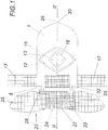
- eine Draufsicht auf eine erfindungsgemäße Vorrichtung in geöffnetem Zustand,
- Fig. 2
- einen Schnitt entlang der Linie II-II der
Fig. 1 in größerem Maßstab, - Fig. 3
- eine der
Fig. 1 entsprechende Ansicht der Vorrichtung in geschlossenem Zustand, - Fig. 4
- einen Schnitt entlang der Linie IV-IV der
Fig. 3 , ebenfalls in größerem Maßstab und - Fig. 5
- eine schematische Ansicht der Zuschnittschablonen von Ober- und Teil zur besseren Erläuterung der geometrischen Verhältnisse.
- Fig. 1
- a plan view of a device according to the invention in the open state,
- Fig. 2
- a section along the line II-II of
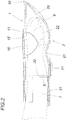
Fig. 1 on a larger scale, - Fig. 3
- one of the
Fig. 1 corresponding view of the device in the closed state, - Fig. 4
- a section along the line IV-IV of
Fig. 3 , also on a larger scale and - Fig. 5
- a schematic view of the cutting templates of the upper and part for a better explanation of the geometric relationships.
Eine erfindungsgemäße Vorrichtung für den Pfotenschutz umfasst ein Oberteil 1 und ein Unterteil 2, die randseitig abschnittsweise miteinander verbunden sind. Sowohl das Oberteil 1 als auch das Unterteil 2 weisen je einen Schaftabschnitt 3, 4 und einen Pfotenabschnitt 5, 6 auf, wobei das Oberteil 1 und das Unterteil 2 randseitig so miteinander verbunden sind, dass sich ein Schaft 7 mit einem offenen Schaftende 8 und einer an der dem Schaftende 8 gegenüberliegenden Seite des Schaftes 7 anschließenden, abgeschlossenen Pfotenaufnahme 9 ergibt.A device according to the invention for paw protection comprises an
Erfindungsgemäß sind der Pfotenabschnitt 6 des Unterteils 2 und der Pfotenabschnitt 5 des Oberteils 1 jeweils als Halboval ausgebildet, das mit seiner Längs- beziehungsweise Querachse an den jeweiligen Schaftabschnitt 3, 4 des Ober- beziehungsweise Unterteils 1, 2 anschließt Der Pfotenabschnitt 6 des Unterteils 2 ist dabei als Halboval ausgebildet, das entlang seiner Querachse 10 an den Schaftabschnitt 4 des Unterteils 2 anschließt, während der Pfotenabschnitt 5 des Oberteils 1 als Halboval ausgebildet ist, das entlang seiner Längsachse 11 an den Schaftabschnitt 3 des Oberteils 1 anschließt. Die Längsachse 11 des Oberteils 1 und die Querachse des Unterteiles 2 sind dabei zueinander parallel, wie dies insbesondere der
Um zu verhindern, dass es bei angelegtem Pfotenschutz zu einer falschen Laufbewegung bzw. gar zu einem Umknicken oder Überrollen der Pfote in die falsche Richtung kommt, weist das entlang seiner Längsachse 11 an den Schaftabschnitt des Oberteils 1 anschließende Halboval an dem dem Schaftabschnitt 4 abgewandten Ende seiner Querachse einen spitz zu einem Scheitelpunkt zulaufenden Endabschnitt 30 auf. Folglich krümmt sich die Pfotenaufnahme in ihrem vorderen, dem Schaft 7 abgewandten Endbereich 30 etwas nach oben, sodass bei der Laufbewegung sichergestellt wird, dass stets der Unterteil 2 auf dem Untergrund zur Auflage gelangt und es zu keinem Überrollen auf das Oberteil 1 der Vorrichtung kommtIn order to prevent the wrong running movement or even bending or rolling over of the paw in the wrong direction when the paw protector is on, the semi-oval adjacent to the shaft section of the
Der Schaftabschnitt 3 des Oberteils 1 ist in der dargestellten Ausführungsform von einem Oval 12 durchbrochen, dass von einem umfangseitig am Oberteil 1 aufliegenden Abdeckteil 13 als Aussteifung verschlossen ist. Um bei einer Krümmung des Ovalausschnittes, die sich beim erfindungsgemäßen Pfotenschutz zwangsläufig einstellt, eine Faltenbildung zu vermeiden, können die Endabschnitte der Längs- und Querachse des Ovals 12 durch Aussparungen 14 im Schaftabschnitt 3 des Oberteils 1 erweitert sein, in der in den Figuren dargestellten Ausführungsform weist der Abdeckteil 13 mehrere verteilte Belüftungsöffnungen 15 auf, die mit einer atmungsaktiven Membran 16 wasserdicht verschlossen ist. Das Vorsehen mehrerer Belüftungsöffnungen 15 sorgt dabei dafür, dass zu keinem unbeabsichtigten Faltenwurf kommt.In the embodiment shown, the
Um die erfindungsgemäße Vorrichtung an unterschiedliche Pfotengrößen anpassen zu können, sind im Bereich des offenen Schaftendes 8 zwei das Oberteil 1 mit dem Unterteil 2 verbindende Spannverschlüsse 17 vorgesehen, die in der dargestellten Ausführungsform als Klettverschlüsse ausgebildet sind. Beim Verschließen der Spannverschlüsse 17 wird, wie in der
Um zu verhindern, dass sich der Pfotenschutz unbeabsichtigt löst oder durch äußere Einwirkung abgezogen werden kann, weist die dargestellte Ausführungsform einen Abziehschutz 23 auf, zu dem das offene Schaftende 8 des Unterteils 2 verlängert ist. Dieser Abziehschutz 23 umfasst ein Basisteil 24, an das zwei flügelförmige Schließteile 25 anschließen, die unter Ausbildung eines sich vom Schaft 7 wegverjüngenden Konus um die Tierpfote 22 geschlossen werden können, wie der
Um darüber hinaus auch im Bereich des Abziehschutzes eine Faltenbildung und Materialermüdung zu vermeiden, sind in der dargestellten Ausfuhrungsform die Randbereiche des Abziehschutzes 23 beziehungsweise dessen Basisteils 24 im Übergang zum Schaftabschnitt 4 des Unterteils 2 mit kreisförmigen Aussparungen 28 versehen.In order to avoid wrinkling and material fatigue also in the area of the peel-off guard, the edge areas of the peel-
Claims (10)
- A device for protecting paws, comprising an upper part and a lower part (1, 2), each having a shank portion (3, 4) and a paw portion (5, 6), the upper and lower parts (1, 2) being connected in sections at the edges, forming a shank (7) and a paw holder (9) adjacent to the shank (7), the paw portion (6) of the lower part (2) is in semi-oval shape adjoining, along its transversal axis (10), the shank portion (4) of the lower part (2), characterised in that
the paw portion (5) of the upper part (1) is in semi-oval shape adjoining, along its longitudinal axis (11), the shank portion (3) of the upper part (1). - The device according to claim 1, characterised in that:
both semi-ovals are arranged symmetrically with respect to the shank axis (26), and in that the semi-oval adjoining, along its longitudinal axis (11), the shank portion (3) of the upper part (1) has, at the end of its transversal axis facing away from the shank portion (3), an end portion tapered to form an apex. - The device according to claim 1 or claim 2, characterised in that the shank portion (3) of the upper part (1) has a reinforcement.
- The device according to claim 3, characterised in that the shank portion (3) of the upper part (1) is penetrated by an oval (12) which is closed off by a cover part (13) circumferentially resting on the upper part (1) as reinforcement and which is complemented by cut-outs (14) in the shank portion (3) of the upper part (1), in the area of the end portions of the longitudinal and transversal axes thereof.
- The device according to claim 4, characterised in that the cover part (13) has a vent opening (15) sealed with a breathable membrane (16).
- The device according to any one of the claims 1 to 5, characterised in that two tension fasteners (17) connecting the upper part (1) to the lower part (2) are located in the area of the open shank end (8) on the outside of the shank (7).
- The device according to any one of the claims 1 to 6, characterised in that the shank portion (4) of the lower part (2) is extended beyond the open shank end (8) toward a slip-off protection (23) which in the closed position is tapered conically in a direction away from the shank (7).
- The device according to claim 7, characterised in that the slip-off protection (23) is equipped with a non-slip coating in sections on its inside.
- The device according to one of the claims 1 to 8, characterised in that the upper and lower parts (1, 2) are made of polyurethane foam.
- The device according to claim 9, characterised in that the polyurethane foam has a material thickness of 1 to 3 mm and a tensile strength of about 8.1 N/mm2.
Applications Claiming Priority (2)
| Application Number | Priority Date | Filing Date | Title |
|---|---|---|---|
| ATA50621/2017A AT519658B1 (en) | 2017-07-25 | 2017-07-25 | Device for paw protection |
| PCT/AT2018/000064 WO2019018864A1 (en) | 2017-07-25 | 2018-07-13 | Device for protecting paws |
Publications (2)
| Publication Number | Publication Date |
|---|---|
| EP3657939A1 EP3657939A1 (en) | 2020-06-03 |
| EP3657939B1 true EP3657939B1 (en) | 2021-06-23 |
Family
ID=63529134
Family Applications (1)
| Application Number | Title | Priority Date | Filing Date |
|---|---|---|---|
| EP18793553.1A Active EP3657939B1 (en) | 2017-07-25 | 2018-07-13 | Device for protecting paws |
Country Status (4)
| Country | Link |
|---|---|
| US (1) | US20210153460A1 (en) |
| EP (1) | EP3657939B1 (en) |
| AT (1) | AT519658B1 (en) |
| WO (1) | WO2019018864A1 (en) |
Families Citing this family (5)
| Publication number | Priority date | Publication date | Assignee | Title |
|---|---|---|---|---|
| AU2019311578A1 (en) * | 2018-07-23 | 2021-03-11 | Scootboot Pty Ltd | Strap for equine hoof boot and boot |
| US20230049781A1 (en) * | 2021-08-11 | 2023-02-16 | April Chester | Lightweight and flexible canine footwear |
| DE202021003349U1 (en) | 2021-10-28 | 2021-12-10 | Dieter Pfaff | Multifunctional paw lift shoe orthosis |
| USD992836S1 (en) * | 2023-01-16 | 2023-07-18 | Huimin Ding | Pet shoe |
| DE202023000932U1 (en) | 2023-04-27 | 2023-12-11 | Dieter Pfaff | Multifunctional - multi-part - therapy and relief orthosis |
Family Cites Families (15)
| Publication number | Priority date | Publication date | Assignee | Title |
|---|---|---|---|---|
| US5495828A (en) * | 1994-06-30 | 1996-03-05 | Solomon; Irving | Animal boots with detachable, vertically adjustable fastening strap |
| US6186097B1 (en) * | 1998-01-17 | 2001-02-13 | Sandra Brockmann | Protection shoe for the paw of a dog |
| US6470832B1 (en) * | 2000-02-16 | 2002-10-29 | Charlton Peacock | Animal boots |
| GB2361167A (en) * | 2000-04-12 | 2001-10-17 | Miller Lawrence | Animal shoe |
| US9380763B2 (en) * | 2005-08-16 | 2016-07-05 | Elizabeth J. Krottinger | Dog shoe |
| US20070039565A1 (en) * | 2005-08-16 | 2007-02-22 | Presch, Llc | Dog shoes |
| US8109241B2 (en) * | 2005-08-29 | 2012-02-07 | Mary Kathleen Wrenwood Maloney | Dog boot |
| US20070175409A1 (en) * | 2006-01-31 | 2007-08-02 | Rod Vogelman | Disposable bootie for pets |
| US7677206B1 (en) * | 2006-03-08 | 2010-03-16 | Southworth William W | Orthopedic boot for animals |
| WO2009120723A2 (en) * | 2008-03-24 | 2009-10-01 | Paxton Stephen E | Kevlar dog boots |
| US8176880B2 (en) * | 2009-08-21 | 2012-05-15 | I Did It, Inc. | Therapeutic pet boot |
| US20120191028A1 (en) * | 2010-02-13 | 2012-07-26 | Therese Leigh Entler | Veterinary dressing sock |
| USD633258S1 (en) * | 2010-03-17 | 2011-02-22 | Judith Benattar | Boot for animals |
| US10542729B2 (en) * | 2013-06-10 | 2020-01-28 | Beth Morris | Non-slip therapeutic dog boots |
| US20160106066A1 (en) * | 2014-10-15 | 2016-04-21 | Richard Arthur Montgomery | Protective Footwear for Canines |
-
2017
- 2017-07-25 AT ATA50621/2017A patent/AT519658B1/en not_active IP Right Cessation
-
2018
- 2018-07-13 US US16/633,154 patent/US20210153460A1/en not_active Abandoned
- 2018-07-13 WO PCT/AT2018/000064 patent/WO2019018864A1/en unknown
- 2018-07-13 EP EP18793553.1A patent/EP3657939B1/en active Active
Also Published As
| Publication number | Publication date |
|---|---|
| AT519658A4 (en) | 2018-09-15 |
| AT519658B1 (en) | 2018-09-15 |
| US20210153460A1 (en) | 2021-05-27 |
| WO2019018864A1 (en) | 2019-01-31 |
| EP3657939A1 (en) | 2020-06-03 |
Similar Documents
| Publication | Publication Date | Title |
|---|---|---|
| EP3657939B1 (en) | Device for protecting paws | |
| WO2007006538A1 (en) | Protective glove made from metal chain mail | |
| CH671342A5 (en) | ||
| DE60303293T2 (en) | CLOTHING PIECE WITH INNER COLLAR | |
| DE3727701A1 (en) | Protective helmet | |
| EP0088378A1 (en) | Safety school satchel | |
| DE102005061582B4 (en) | Protector jacket, especially for motorcyclists | |
| DE2952406A1 (en) | Integral crash helmet with cushioned inner layer - has removable lower peripheral segment allowing easy removal of helmet after accident | |
| EP3203832B1 (en) | Shoe for a hoofed animal, preferably a horse | |
| DE60106663T2 (en) | Safety shoulder belt for overalls with integrated life jacket | |
| DE3811900C2 (en) | ||
| DE102020207560A1 (en) | Face mask for use in water sports | |
| DE102020003579A1 (en) | Bag for foldable protective cover of a guide device for pets | |
| EP2363033B1 (en) | Protector for shoes | |
| DE602004011338T2 (en) | Gaiter for animals | |
| DE202010008449U1 (en) | Gaiter for protecting a leg of a horse, in particular for protecting the leg of a tube and the shackles of jumping horses | |
| DE202010008448U1 (en) | Gaiter for the protection of a horse's leg, in particular for the protection of the leg of a tube and the fetter of jumping horses | |
| WO2016055387A1 (en) | Hoof shoe for a hoofed animal, preferably a horse | |
| AT262840B (en) | Protective sleeve for ski boots | |
| DE3344699A1 (en) | Spiked collar for animals, especially dogs | |
| DE1460042C (en) | Holders for garments | |
| DE202018104078U1 (en) | Protective element for a protection device for body parts and protective device | |
| DE202009009626U1 (en) | Dog protector suit | |
| DE202018107290U1 (en) | Neck for athletes and system of neck and shin guards | |
| DE202008006086U1 (en) | Protection device for the fetlock joint of horses |
Legal Events
| Date | Code | Title | Description |
|---|---|---|---|
| STAA | Information on the status of an ep patent application or granted ep patent |
Free format text: STATUS: UNKNOWN |
|
| STAA | Information on the status of an ep patent application or granted ep patent |
Free format text: STATUS: THE INTERNATIONAL PUBLICATION HAS BEEN MADE |
|
| PUAI | Public reference made under article 153(3) epc to a published international application that has entered the european phase |
Free format text: ORIGINAL CODE: 0009012 |
|
| STAA | Information on the status of an ep patent application or granted ep patent |
Free format text: STATUS: REQUEST FOR EXAMINATION WAS MADE |
|
| 17P | Request for examination filed |
Effective date: 20200221 |
|
| AK | Designated contracting states |
Kind code of ref document: A1 Designated state(s): AL AT BE BG CH CY CZ DE DK EE ES FI FR GB GR HR HU IE IS IT LI LT LU LV MC MK MT NL NO PL PT RO RS SE SI SK SM TR |
|
| AX | Request for extension of the european patent |
Extension state: BA ME |
|
| DAV | Request for validation of the european patent (deleted) | ||
| DAX | Request for extension of the european patent (deleted) | ||
| GRAP | Despatch of communication of intention to grant a patent |
Free format text: ORIGINAL CODE: EPIDOSNIGR1 |
|
| STAA | Information on the status of an ep patent application or granted ep patent |
Free format text: STATUS: GRANT OF PATENT IS INTENDED |
|
| INTG | Intention to grant announced |
Effective date: 20210409 |
|
| GRAS | Grant fee paid |
Free format text: ORIGINAL CODE: EPIDOSNIGR3 |
|
| GRAA | (expected) grant |
Free format text: ORIGINAL CODE: 0009210 |
|
| STAA | Information on the status of an ep patent application or granted ep patent |
Free format text: STATUS: THE PATENT HAS BEEN GRANTED |
|
| AK | Designated contracting states |
Kind code of ref document: B1 Designated state(s): AL AT BE BG CH CY CZ DE DK EE ES FI FR GB GR HR HU IE IS IT LI LT LU LV MC MK MT NL NO PL PT RO RS SE SI SK SM TR |
|
| REG | Reference to a national code |
Ref country code: GB Ref legal event code: FG4D Free format text: NOT ENGLISH |
|
| REG | Reference to a national code |
Ref country code: CH Ref legal event code: EP |
|
| REG | Reference to a national code |
Ref country code: DE Ref legal event code: R096 Ref document number: 502018005860 Country of ref document: DE Ref country code: AT Ref legal event code: REF Ref document number: 1403458 Country of ref document: AT Kind code of ref document: T Effective date: 20210715 |
|
| REG | Reference to a national code |
Ref country code: IE Ref legal event code: FG4D Free format text: LANGUAGE OF EP DOCUMENT: GERMAN |
|
| REG | Reference to a national code |
Ref country code: LT Ref legal event code: MG9D |
|
| PG25 | Lapsed in a contracting state [announced via postgrant information from national office to epo] |
Ref country code: BG Free format text: LAPSE BECAUSE OF FAILURE TO SUBMIT A TRANSLATION OF THE DESCRIPTION OR TO PAY THE FEE WITHIN THE PRESCRIBED TIME-LIMIT Effective date: 20210923 Ref country code: FI Free format text: LAPSE BECAUSE OF FAILURE TO SUBMIT A TRANSLATION OF THE DESCRIPTION OR TO PAY THE FEE WITHIN THE PRESCRIBED TIME-LIMIT Effective date: 20210623 Ref country code: LT Free format text: LAPSE BECAUSE OF FAILURE TO SUBMIT A TRANSLATION OF THE DESCRIPTION OR TO PAY THE FEE WITHIN THE PRESCRIBED TIME-LIMIT Effective date: 20210623 Ref country code: HR Free format text: LAPSE BECAUSE OF FAILURE TO SUBMIT A TRANSLATION OF THE DESCRIPTION OR TO PAY THE FEE WITHIN THE PRESCRIBED TIME-LIMIT Effective date: 20210623 |
|
| PG25 | Lapsed in a contracting state [announced via postgrant information from national office to epo] |
Ref country code: GR Free format text: LAPSE BECAUSE OF FAILURE TO SUBMIT A TRANSLATION OF THE DESCRIPTION OR TO PAY THE FEE WITHIN THE PRESCRIBED TIME-LIMIT Effective date: 20210924 Ref country code: RS Free format text: LAPSE BECAUSE OF FAILURE TO SUBMIT A TRANSLATION OF THE DESCRIPTION OR TO PAY THE FEE WITHIN THE PRESCRIBED TIME-LIMIT Effective date: 20210623 Ref country code: SE Free format text: LAPSE BECAUSE OF FAILURE TO SUBMIT A TRANSLATION OF THE DESCRIPTION OR TO PAY THE FEE WITHIN THE PRESCRIBED TIME-LIMIT Effective date: 20210623 Ref country code: LV Free format text: LAPSE BECAUSE OF FAILURE TO SUBMIT A TRANSLATION OF THE DESCRIPTION OR TO PAY THE FEE WITHIN THE PRESCRIBED TIME-LIMIT Effective date: 20210623 Ref country code: NO Free format text: LAPSE BECAUSE OF FAILURE TO SUBMIT A TRANSLATION OF THE DESCRIPTION OR TO PAY THE FEE WITHIN THE PRESCRIBED TIME-LIMIT Effective date: 20210923 |
|
| REG | Reference to a national code |
Ref country code: NL Ref legal event code: MP Effective date: 20210623 |
|
| PG25 | Lapsed in a contracting state [announced via postgrant information from national office to epo] |
Ref country code: SM Free format text: LAPSE BECAUSE OF FAILURE TO SUBMIT A TRANSLATION OF THE DESCRIPTION OR TO PAY THE FEE WITHIN THE PRESCRIBED TIME-LIMIT Effective date: 20210623 Ref country code: NL Free format text: LAPSE BECAUSE OF FAILURE TO SUBMIT A TRANSLATION OF THE DESCRIPTION OR TO PAY THE FEE WITHIN THE PRESCRIBED TIME-LIMIT Effective date: 20210623 Ref country code: RO Free format text: LAPSE BECAUSE OF FAILURE TO SUBMIT A TRANSLATION OF THE DESCRIPTION OR TO PAY THE FEE WITHIN THE PRESCRIBED TIME-LIMIT Effective date: 20210623 Ref country code: PT Free format text: LAPSE BECAUSE OF FAILURE TO SUBMIT A TRANSLATION OF THE DESCRIPTION OR TO PAY THE FEE WITHIN THE PRESCRIBED TIME-LIMIT Effective date: 20211025 Ref country code: CZ Free format text: LAPSE BECAUSE OF FAILURE TO SUBMIT A TRANSLATION OF THE DESCRIPTION OR TO PAY THE FEE WITHIN THE PRESCRIBED TIME-LIMIT Effective date: 20210623 Ref country code: SK Free format text: LAPSE BECAUSE OF FAILURE TO SUBMIT A TRANSLATION OF THE DESCRIPTION OR TO PAY THE FEE WITHIN THE PRESCRIBED TIME-LIMIT Effective date: 20210623 Ref country code: EE Free format text: LAPSE BECAUSE OF FAILURE TO SUBMIT A TRANSLATION OF THE DESCRIPTION OR TO PAY THE FEE WITHIN THE PRESCRIBED TIME-LIMIT Effective date: 20210623 Ref country code: ES Free format text: LAPSE BECAUSE OF FAILURE TO SUBMIT A TRANSLATION OF THE DESCRIPTION OR TO PAY THE FEE WITHIN THE PRESCRIBED TIME-LIMIT Effective date: 20210623 |
|
| PG25 | Lapsed in a contracting state [announced via postgrant information from national office to epo] |
Ref country code: PL Free format text: LAPSE BECAUSE OF FAILURE TO SUBMIT A TRANSLATION OF THE DESCRIPTION OR TO PAY THE FEE WITHIN THE PRESCRIBED TIME-LIMIT Effective date: 20210623 |
|
| REG | Reference to a national code |
Ref country code: CH Ref legal event code: PL |
|
| REG | Reference to a national code |
Ref country code: DE Ref legal event code: R097 Ref document number: 502018005860 Country of ref document: DE |
|
| PG25 | Lapsed in a contracting state [announced via postgrant information from national office to epo] |
Ref country code: MC Free format text: LAPSE BECAUSE OF FAILURE TO SUBMIT A TRANSLATION OF THE DESCRIPTION OR TO PAY THE FEE WITHIN THE PRESCRIBED TIME-LIMIT Effective date: 20210623 |
|
| REG | Reference to a national code |
Ref country code: BE Ref legal event code: MM Effective date: 20210731 |
|
| PG25 | Lapsed in a contracting state [announced via postgrant information from national office to epo] |
Ref country code: LI Free format text: LAPSE BECAUSE OF NON-PAYMENT OF DUE FEES Effective date: 20210731 Ref country code: DK Free format text: LAPSE BECAUSE OF FAILURE TO SUBMIT A TRANSLATION OF THE DESCRIPTION OR TO PAY THE FEE WITHIN THE PRESCRIBED TIME-LIMIT Effective date: 20210623 Ref country code: CH Free format text: LAPSE BECAUSE OF NON-PAYMENT OF DUE FEES Effective date: 20210731 |
|
| PGFP | Annual fee paid to national office [announced via postgrant information from national office to epo] |
Ref country code: DE Payment date: 20220110 Year of fee payment: 4 |
|
| PLBE | No opposition filed within time limit |
Free format text: ORIGINAL CODE: 0009261 |
|
| STAA | Information on the status of an ep patent application or granted ep patent |
Free format text: STATUS: NO OPPOSITION FILED WITHIN TIME LIMIT |
|
| 26N | No opposition filed |
Effective date: 20220324 |
|
| PG25 | Lapsed in a contracting state [announced via postgrant information from national office to epo] |
Ref country code: LU Free format text: LAPSE BECAUSE OF NON-PAYMENT OF DUE FEES Effective date: 20210713 Ref country code: AL Free format text: LAPSE BECAUSE OF FAILURE TO SUBMIT A TRANSLATION OF THE DESCRIPTION OR TO PAY THE FEE WITHIN THE PRESCRIBED TIME-LIMIT Effective date: 20210623 |
|
| PG25 | Lapsed in a contracting state [announced via postgrant information from national office to epo] |
Ref country code: IT Free format text: LAPSE BECAUSE OF FAILURE TO SUBMIT A TRANSLATION OF THE DESCRIPTION OR TO PAY THE FEE WITHIN THE PRESCRIBED TIME-LIMIT Effective date: 20210623 Ref country code: IE Free format text: LAPSE BECAUSE OF NON-PAYMENT OF DUE FEES Effective date: 20210713 Ref country code: FR Free format text: LAPSE BECAUSE OF NON-PAYMENT OF DUE FEES Effective date: 20210823 Ref country code: BE Free format text: LAPSE BECAUSE OF NON-PAYMENT OF DUE FEES Effective date: 20210731 |
|
| REG | Reference to a national code |
Ref country code: DE Ref legal event code: R119 Ref document number: 502018005860 Country of ref document: DE |
|
| GBPC | Gb: european patent ceased through non-payment of renewal fee |
Effective date: 20220713 |
|
| PG25 | Lapsed in a contracting state [announced via postgrant information from national office to epo] |
Ref country code: GB Free format text: LAPSE BECAUSE OF NON-PAYMENT OF DUE FEES Effective date: 20220713 Ref country code: DE Free format text: LAPSE BECAUSE OF NON-PAYMENT OF DUE FEES Effective date: 20230201 |
|
| PG25 | Lapsed in a contracting state [announced via postgrant information from national office to epo] |
Ref country code: CY Free format text: LAPSE BECAUSE OF FAILURE TO SUBMIT A TRANSLATION OF THE DESCRIPTION OR TO PAY THE FEE WITHIN THE PRESCRIBED TIME-LIMIT Effective date: 20210623 |
|
| PG25 | Lapsed in a contracting state [announced via postgrant information from national office to epo] |
Ref country code: HU Free format text: LAPSE BECAUSE OF FAILURE TO SUBMIT A TRANSLATION OF THE DESCRIPTION OR TO PAY THE FEE WITHIN THE PRESCRIBED TIME-LIMIT; INVALID AB INITIO Effective date: 20180713 |