EP3657177A1 - Automatic analysis device - Google Patents
Automatic analysis device Download PDFInfo
- Publication number
- EP3657177A1 EP3657177A1 EP18834440.2A EP18834440A EP3657177A1 EP 3657177 A1 EP3657177 A1 EP 3657177A1 EP 18834440 A EP18834440 A EP 18834440A EP 3657177 A1 EP3657177 A1 EP 3657177A1
- Authority
- EP
- European Patent Office
- Prior art keywords
- expendable
- analysis device
- automatic analysis
- item
- transport mechanism
- Prior art date
- Legal status (The legal status is an assumption and is not a legal conclusion. Google has not performed a legal analysis and makes no representation as to the accuracy of the status listed.)
- Granted
Links
Images


Classifications
-
- G—PHYSICS
- G01—MEASURING; TESTING
- G01N—INVESTIGATING OR ANALYSING MATERIALS BY DETERMINING THEIR CHEMICAL OR PHYSICAL PROPERTIES
- G01N35/00—Automatic analysis not limited to methods or materials provided for in any single one of groups G01N1/00 - G01N33/00; Handling materials therefor
- G01N35/00584—Control arrangements for automatic analysers
- G01N35/00722—Communications; Identification
- G01N35/00732—Identification of carriers, materials or components in automatic analysers
-
- G—PHYSICS
- G01—MEASURING; TESTING
- G01N—INVESTIGATING OR ANALYSING MATERIALS BY DETERMINING THEIR CHEMICAL OR PHYSICAL PROPERTIES
- G01N35/00—Automatic analysis not limited to methods or materials provided for in any single one of groups G01N1/00 - G01N33/00; Handling materials therefor
- G01N35/02—Automatic analysis not limited to methods or materials provided for in any single one of groups G01N1/00 - G01N33/00; Handling materials therefor using a plurality of sample containers moved by a conveyor system past one or more treatment or analysis stations
- G01N35/04—Details of the conveyor system
-
- G—PHYSICS
- G01—MEASURING; TESTING
- G01N—INVESTIGATING OR ANALYSING MATERIALS BY DETERMINING THEIR CHEMICAL OR PHYSICAL PROPERTIES
- G01N35/00—Automatic analysis not limited to methods or materials provided for in any single one of groups G01N1/00 - G01N33/00; Handling materials therefor
- G01N35/00584—Control arrangements for automatic analysers
- G01N35/00722—Communications; Identification
- G01N35/00732—Identification of carriers, materials or components in automatic analysers
- G01N2035/00792—Type of components bearing the codes, other than sample carriers
-
- G—PHYSICS
- G01—MEASURING; TESTING
- G01N—INVESTIGATING OR ANALYSING MATERIALS BY DETERMINING THEIR CHEMICAL OR PHYSICAL PROPERTIES
- G01N35/00—Automatic analysis not limited to methods or materials provided for in any single one of groups G01N1/00 - G01N33/00; Handling materials therefor
- G01N35/02—Automatic analysis not limited to methods or materials provided for in any single one of groups G01N1/00 - G01N33/00; Handling materials therefor using a plurality of sample containers moved by a conveyor system past one or more treatment or analysis stations
- G01N35/04—Details of the conveyor system
- G01N2035/0401—Sample carriers, cuvettes or reaction vessels
- G01N2035/0429—Sample carriers adapted for special purposes
- G01N2035/0434—Sample carriers adapted for special purposes in the form of a syringe or pipette tip
-
- G—PHYSICS
- G01—MEASURING; TESTING
- G01N—INVESTIGATING OR ANALYSING MATERIALS BY DETERMINING THEIR CHEMICAL OR PHYSICAL PROPERTIES
- G01N35/00—Automatic analysis not limited to methods or materials provided for in any single one of groups G01N1/00 - G01N33/00; Handling materials therefor
- G01N35/02—Automatic analysis not limited to methods or materials provided for in any single one of groups G01N1/00 - G01N33/00; Handling materials therefor using a plurality of sample containers moved by a conveyor system past one or more treatment or analysis stations
- G01N35/04—Details of the conveyor system
- G01N2035/0439—Rotary sample carriers, i.e. carousels
- G01N2035/0443—Rotary sample carriers, i.e. carousels for reagents
-
- G—PHYSICS
- G01—MEASURING; TESTING
- G01N—INVESTIGATING OR ANALYSING MATERIALS BY DETERMINING THEIR CHEMICAL OR PHYSICAL PROPERTIES
- G01N35/00—Automatic analysis not limited to methods or materials provided for in any single one of groups G01N1/00 - G01N33/00; Handling materials therefor
- G01N35/10—Devices for transferring samples or any liquids to, in, or from, the analysis apparatus, e.g. suction devices, injection devices
- G01N2035/1027—General features of the devices
- G01N2035/103—General features of the devices using disposable tips
Definitions
- the present invention relates to an automatic analysis device, and to the automatic analysis device including a mechanism that transports a plurality of types of expendable items, for example.
- Patent Literature 1 describes a technique that prevents inaccurate dispensing due to detachment after mounting a dispensing chip by monitoring whether the dispensing chip is appropriately mounted on a dispensing mechanism portion in the transfer period of the dispensing mechanism portion by a transfer portion.
- Patent Literature 1 Japanese Unexamined Patent Application Publication No. 2005-201769
- the automatic analysis device includes various transport mechanisms that appropriately transport a plurality of types of such expendable items and discard used expendable items.
- Various transport mechanisms sometimes include a mechanism that transports a plurality of types of expendable items in common.
- a plurality of types of expendable items has different shapes, materials, uses, and the like.
- an additional process for example, is sometimes necessary from the viewpoint of safety, and the importance of sorting and discarding expendable items is increasing.
- the Patent Literature 1 does not have a viewpoint relating to the sorting and discarding of expendable items.
- a plurality of types of expendable items is sometimes collected at one place.
- the present invention is made in view of such circumstances, and one of objects of the present invention is to provide an automatic analysis device that can appropriately separately discard expendable items.
- An automatic analysis device has a common transport mechanism that transports types of expendable items by a common mechanism, transport paths that are provided separately from the common transport mechanism, and a determination portion that determines a type of the expendable item being transported by the common transport mechanism.
- the automatic analysis device is controlled to select one of the transport paths according to a determination result of the determination portion and to transport the expendable item transported from the common transport mechanism via the selected transport path.
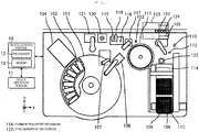
- FIG. 1 is a schematic view illustrating a configuration example of a main portion of an automatic analysis device according to a first embodiment of the present invention.
- the automatic analysis device illustrated in FIG. 1 is a biochemical analysis device or an immunity analysis device, for example, that analyzes specific components included in a specimen (a sample), such as blood serum and urine, for example.
- a specimen a sample
- the automatic analysis device is not limited to these devices specifically.
- the automatic analysis device may be a mass spectrometer used for clinical examinations, or a clotting analysis device that measures the clotting time of blood, and any other device, for example.
- the automatic analysis device may be a composite appropriately combining a mass spectrometer, a clotting analysis device, a biochemical analysis device, an immunity analysis device, and any other device, or may be in a form of an automatic analysis system applying these devices.
- the automatic analysis device illustrated in FIG. 1 (e.g. an immunity analysis device) includes a transport device that transports a sample rack 101 on which a sample is placed, a reagent disk 103, a storage box 110, a reaction portion 111, a magnetic separation mechanism including a magnetic separator 116, a detection portion 120, and various transport mechanisms that transport reagent containers or reaction containers to the portions of the device.
- the automatic analysis device includes a device control portion 10 that control the overall operation of the device and a device operation portion 11 serving as an interface between the device control portion 10 and an operator.
- the device control portion 10 includes a processor 12 and a memory 13 including a RAM (Random Access Memory), ROM (Read Only Memory), and a HDD (Hard Disk Drive), for example, and controls the operation sequence of the overall device by processing programs by the processor 12.
- the device control portion 10 is not limited to the configuration using such program processing, and may have a configuration using dedicated hardware processing, or may have a configuration using an appropriate combination of program processing and hardware processing.
- the device operation portion 11 is configured of a display portion, such as a display, for example, and an input device, such as a mouse and a keyboard.
- the transport device places the sample rack 101 on a belt, and transports the sample rack 101 with the belt.
- the transport device may be a disk that places the sample on the disk and transports the sample by rotation, or may be a device that catches the sample rack 101 and transports the sample rack 101 by lifting operation.
- a reagent container 102 containing a reagent and magnetic particles necessary to immune reaction is housed. This reagent container 102 is attached with a cover.
- a reaction container 108 used for reaction and a sample dispensing chip 109 used for splitting and dispensing of a sample (in the following, referred to as a chip) are housed.
- the reaction container 108 and the chip 109 are expendable items used in analysis.
- the reaction container 108 is placed, and the reaction between the sample and the reagent is performed in the reaction container 108 that is placed.
- the reaction portion 111 has a temperature control mechanism necessary to the reaction between the sample and the reagent.
- Various transport mechanisms include a common transport mechanism 114 and a transport mechanism 117.
- the common transport mechanism 114 transports a plurality of types of expendable items using a common mechanism.
- the common transport mechanism 114 transports the reaction container 108 to the reaction portion 111, and transports the chip 109 to a buffer 113.
- the buffer 113 is a temporary storage place for the chip 109 before used for dispensing.
- the common transport mechanism 114 includes a grip mechanism that grips the chip 109 or the reaction container 108 and a rail mechanism that moves the grip mechanism through rails provided in an X-axis, a Y-axis, and a Z-axis directions.
- the transport mechanism 117 appropriately transports the reaction container 108 among the reaction portion 111, the magnetic separator 116, the detection portion 120, and the reaction container discarding port 112.
- the automatic analysis device includes a container lid opening and closing mechanism 104, a sample dispensing probe 105, a reagent dispensing probe 106, and a magnetic particle stirring mechanism 107.
- the sample dispensing probe 105 splits and dispenses a sample from the sample rack 101 with the chip 109 that is stored on the buffer 113 mounted.
- the container lid opening and closing mechanism 104 opens and closes the cover of the reagent container 102.
- the reagent dispensing probe 106 splits and dispenses a reagent and magnetic particles from the reagent container 102.
- the magnetic separation mechanism includes the magnetic separator 116, an impurity suction mechanism 118, and a cleaning liquid discharge mechanism 119.
- the impurity suction mechanism 118 sucks a liquid including an impurity in the reaction container 108 that is transported to the magnetic separator 116.
- the cleaning liquid discharge mechanism 119 discharges a cleaning fluid to the inside of the reaction container 108 transported to the magnetic separator 116.
- a reagent discharge mechanism 121 is provided near the detection portion 120.
- the reagent discharge mechanism 121 discharges a detection reagent to the reaction container 108transported to the detection portion 120.
- the common transport mechanism 114 transports the reaction container 108 from the storage box 110 to the reaction portion 111.
- the common transport mechanism 114 transports the chip 109 to the buffer 113.
- the reaction portion 111 rotates and moves the transported reaction container 108 to a reagent dispensing position.
- the reagent dispensing probe 106 dispenses a reagent from the reagent disk 103 to the reaction container 108 on the reaction portion 111.
- the sample dispensing probe 105 includes a chip holding portion, and mounts the chip 109 transported to the buffer 113 on the chip holding portion b rotational motion and vertical operation.
- the sample dispensing probe 105 mounted on the chip 109 splits a sample from the sample container 124 placed on the sample rack 101, and dispenses the sample to the reaction container 108 moved at the sample dispensing position. In splitting, the sample container 124 is clamped by a container clamping device 123.
- the sample dispensing probe 105 moves the used chip 109 to a chip discarding port 115 by rotational motion and vertical operation, removes the chip 109, and discards the chip 109 to the chip discarding port 115.
- the reaction portion 111 waits for a certain period of time with the reaction container 108 after the sample and the reagent are dispensed being placed, and then moves the reaction container 108 to the reagent dispensing position by rotation.
- the certain period of time is time necessary to the reaction between the sample and the reagent.
- the reagent dispensing probe 106 splits magnetic particles from the reagent disk 103, and dispenses the magnetic particles to the reaction container 108 that has to be at the reagent dispensing position.
- the reaction portion 111 rotates to a predetermined position, and the transport mechanism 117 transports the reaction container 108 on the reaction portion 111 to the magnetic separator 116.
- the magnetic separator 116 separates a magnetic component including a reaction product in the reaction container 108 from a non-magnetic component including an impurity. Specifically, suction by the impurity suction mechanism 118 and discharging the cleaning fluid by the cleaning liquid discharge mechanism 119 are repeated for a several times, and finally, only the magnetic component including the reaction product remains in the reaction container 108.
- the transport mechanism 117 transports the reaction container 108 in which the magnetic component remains to the detection portion 120. After that, the reagent discharge mechanism 121 discharges a reagent for detection to the reaction container 108, and detection is performed.
- the transport mechanism 117 transports the reaction container 108 after detection to the reaction container discarding port 112, and after that, the automatic analysis device repeats the above-described operation to the subsequent samples as well.
- the automatic analysis device in FIG. 1 further includes a type determination portion 122.
- the type determination portion 122 determines a type of the expendable item being transported by the common transport mechanism 114 (in this example, the reaction container 108 or the chip 109).
- the automatic analysis device in FIG. 1 selects any of plurality of transport paths separately provided from the common transport mechanism 114 depending on the determined result of the type determination portion 122, and performs control such that the expendable item from the common transport mechanism 114 is transported through the selected transport path. Ahead of each of the plurality of transport paths, a plurality of discarding ports (in this example, the reaction container discarding port 112 and the chip discarding port 115) is provided.
- the automatic analysis device finally discards an expendable item through the plurality of transport paths. In this regard, in the following, the operation will be described more in detail.
- the reaction container 108 is stored on the storage box 110, and transported with the reaction container 108 gripped by the common transport mechanism 114, and the type is determined at the type determination portion 122.
- the automatic analysis device selects a first transport path that is a path from the position at which the type is determined to the reaction container discarding port 112 depending on the determined result.
- the reaction container 108 is placed on the reaction portion 111 by the common transport mechanism 114.
- the reaction container 108 is moved to the reagent dispensing position or the sample dispensing position by the rotation of the reaction portion 111, gripped by the transport mechanism 117 after the reagent, the sample, and the magnetic particles are dispensed, and placed on the magnetic separator 116.
- the reaction container 108 in which the magnetic component is separated by the magnetic separator 116 is transported to the detection portion 120 by the transport mechanism 117. After that, the reaction container 108 after detection is discarded to the reaction container discarding port 112 by the transport mechanism 117.
- the chip 109 is stored on the storage box 110, transported with the chip 109 gripped by the common transport mechanism 114, and the type is determined at the type determination portion 122.
- the automatic analysis device selects a second transport path that is a path from the position at which the type is determined to the chip discarding port 115 depending on the determined result.
- the chip 109 is placed on the buffer 113 by the common transport mechanism 114.
- the chip 109 is mounted on the sample dispensing probe 105 by the operation of the sample dispensing probe 105.
- the chip 109 is removed from the sample dispensing probe 105 by the operation of the sample dispensing probe 105, and discarded to the chip discarding port 115.
- the reaction container discarding port 112 is not connected to the chip discarding port 115 at a place not illustrated in the drawing, and the expendable item discarded to the reaction container discarding port 112 and the expendable item discarded to the chip discarding port 115 are separately collected. As a result, it is made possible to appropriately sort and discard expendable items.
- the operation range of the common transport mechanism 114 includes the region of the storage box 110 on which the reaction container 108 and the chip 109 are placed.
- the operation range may not include the storage box 110.
- the regular case means the case in which expendable items are used in various processes necessary to analysis and then discarded, like the above-described first transport path or the second transport path.
- the device control portion 10 sequentially manages the transport path of the expendable item based on a predetermined time sequence, and also recognizes in advance a type of the expendable item being transported by the common transport mechanism 114 based on a time sequence. Therefore, in such a case, the type determination portion 122 does not necessarily perform type determination.
- the irregular case means the case in which a predetermined device error (in other words, an abnormality halt) occurs in the transportation of an expendable item by the common transport mechanism 114, for example, or the case in which analysis has to be interrupted in emergency due to various circumstances, and any other cases.
- a predetermined device error in other words, an abnormality halt
- the use of the type determination portion 122 is useful.
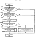
- FIG. 2A is a flowchart is a flowchart illustrating an example of processing contents of a portion of a device control portion in FIG. 1 .
- the device control portion 10 determines whether a discarding process for a transport item is necessary (Step S201). Specifically, the device control portion 10 determines whether an irregular case, such as the occurrence of a device error, occurs. In the case in which the discarding process for the transport item is necessary, the device control portion 10 determines whether the common transport mechanism 114 is transporting a transport item (Step S202).
- the device control portion 10 determines the presence or absence of the transport item by detecting the opening and closing of the gripper. Note that in the case in which the discarding process for the transport item is unnecessary in Step S201, or in the case in which no transport item is present in Step S202, the device control portion 10 ends processes.
- the device control portion 10 causes the type determination portion 122 to determine the type of transport item (Step S203). In the case in which the type determination portion 122 identifies the type, the device control portion 10 performs a discarding process for each type (Steps S204 and S205). On the other hand, in the case in which the type is not identified by the type determination portion 122, the device control portion 10 halts the device operation, and notifies this to the device operation portion 11 (Steps S204 and S206). Note that here, the device control portion 10 halts the device operation in Step S206. However, the device control portion 10 may not halt the device operation and may end processes depending upon circumstances. The device control portion 10 may not perform the process in Step S202, and may determine the type of transport item in Step S203 regardless of the presence or absence of the transport item.
- the transport item is generally an expendable item (in this example, the reaction container 108 or the chip 109).
- the transport item is sometimes a special part due to device debugging.
- An example of a special part includes a fixture used for adjusting the position of the device.
- a process in Step S206 is performed. As a result, a situation in which the special part is discarded can be prevented.
- FIG. 2B is a flowchart illustrating an example of detailed processing contents of a discarding process for each type in FIG. 2A .
- a transport item i.e., an expendable item
- the device control portion 10 instructs the common transport mechanism 114 to transport the chip 109 to the buffer 113 (Steps S211 and S212). Subsequently, the device control portion 10 instructs the sample dispensing probe 105 to discard the chip 109 on the buffer 113 to the chip discarding port 115 (Step S213).
- the device control portion 10 instructs the common transport mechanism 114 to transport the reaction container 108 to the reaction portion 111 (Steps S211 and S214). Subsequently, the device control portion 10 instructs the reaction portion 111 to perform rotation operation (Step S215). After that, the device control portion 10 instructs the transport mechanism 117 to discard the reaction container 108 on the reaction portion 111 to the reaction container discarding port 112 (Step S216).
- the device control portion 10 causes the common transport mechanism 114 to deliver the expendable item to a processing mechanism corresponding to a type of the expendable item, causes the processing mechanism not to perform the original processing that is a part of analysis processed, and causes the processing mechanism to perform the discarding process to the discarding port.
- the device control portion 10 causes the common transport mechanism 114 to deliver the expendable item to the sample dispensing probe 105 as the target processing mechanism is the sample dispensing probe 105, causes the sample dispensing probe 105 not to perform the original dispensing process, and causes the sample dispensing probe 105 to discard the expendable item to the chip discarding port 115.
- the device control portion 10 causes the common transport mechanism 114 to deliver the expendable item to the reaction portion 111 as the target processing mechanisms are the reaction portion 111 and the transport mechanism 117, causes the reaction portion 111 and the transport mechanism 117 not to perform the original process, such as sample dispensing, magnetic separation, and detection, and causes the reaction portion 111 and the transport mechanism 117 to discard the expendable item to the reaction container discarding port 112.
- FIG. 3 is a schematic view illustrating a configuration example of the type determination portion in FIG. 1 .
- the type determination portion 122 in FIG. 3 has a plurality of sensors 302a and 302b that detect the presence or absence of a substance at different coordinates on a detection line 300 in a predetermined uniaxial direction.
- the plurality of sensors 302a and 302b there are known reflective or transmissive photoelectric sensors, sensors using the reflection of ultrasonic waves, sensors that perform detection based on the presence or absence of a contact, an any other sensors.
- the common transport mechanism 114 in FIG. 1 is movable in the X-axis, the Y-axis, and the Z-axis directions with the transport item gripped by a gripper 301.
- the common transport mechanism 114 transports the transport item to the region of the type determination portion 122 on the XY-plane, places the transport item on the detection line 300 (here, on the Z-axis), and then moves the transport item by a specified amount 305 in the Z-axis direction.
- the type determination portion 122 determines the type of transport item based on the detected results of the plurality of sensors 302a and 302b.
- the case is assumed in which the chip 109 that is the transport item (the expendable item) is longer than the reaction container 108 and two sensors 302a and 302b are used.
- the detected results of two sensors 302a and 302b are varied depending on the shape of the transport item (here, the length in the longitudinal direction).
- both of two sensors 302a and 302b detect the presence of a substance.
- one of two sensors 302a and 302b alone detects the presence of a substance.
- the type of transport item can be determined based on the difference in detected results.
- a type determination method it is made possible to determine types by the number of sensors, or by the number of the sensors plus one. That is, when it is the premise that a transport item is present, both of the sensors 302a and 302b detect the absence of a substance in addition to the two types described above, and hence a shorter transport item (e.g. a fixture) can be distinguished. In the case in which it is not the premise that the transport item is present, a sensor is placed at a position at which the shortest transport item possibly transported, for example, can be detected, and hence the type determination portion 122 can also make determination including the presence or absence of the transport item.
- FIG. 4 is a schematic view illustrating a configuration example of the type determination portion in FIG. 1 in an automatic analysis device according to a second embodiment of the present invention.
- a type determination portion 122 in FIG. 4 has a sensor 402 that detects the presence or absence of a substance at predetermined coordinates on a detection line 300 in a predetermined uniaxial direction. That is, the type determination portion 122 includes a plurality of sensors in FIG. 3 , but the type determination portion 122 includes one sensor 402 in FIG. 4 .
- a common transport mechanism 114 places a transport item on the detection line 300, and moves the transport item on the detection line 300.
- the type determination portion 122 in FIG. 4 determines the type of transport item based on the movement amount of the common transport mechanism 114 necessary to the sensor 402 that detects the presence of a substance.
- a difference occurs in the movement amount of the common transport mechanism 114 until the sensor 402 detects the presence of a substance depending on the shape of the transport item (here, the length in the longitudinal direction).
- the transport item is a chip 109
- a predetermined movement amount 405 is necessary until the sensor 402 detects the presence of a substance.
- the transport item is a reaction container 108 shorter than the chip 109
- a movement amount 407 greater than the movement amount 405 is necessary until the sensor 402 detects the presence of a substance.
- the type of transport item can be determined based on the difference in this movement amount.
- the effects similar to the case of the first embodiment are obtained.
- a range is determined on the movement amount taking into account of dimension differences due to individual differences of transport items and movement amount errors of the common transport mechanism 114, and it is fine that the transport item is in association with the range.
- the type of transport item is determined based on the difference in the movement amount until the sensor detects the presence of a substance.
- the type of transport item may be determined based on the difference in the movement amount until the sensor detects the absence of a substance. That is, the common transport mechanism 114 may be moved until the absence of a substance is detected as the state in which the presence of a substance is detected is the initial state.
- the common transport mechanism 114 is moved with the sensor fixed.
- the sensor may be moved by the common transport mechanism 114 fixed.
- FIGS. 5A and 5B are schematic views illustrating a configuration example of a type determination portion in an automatic analysis device according to a third embodiment of the present invention.
- a common installation portion 501 is sometimes provided on transport paths for a plurality of types of transport items.
- a plurality of types of transport items is placed in common.
- the common transport mechanism 114 for example, can determine the type of transport item with transport items placed on the common installation portion 501.
- the common installation portion 501 is provided with at least one sensor 502.
- the sensor 502 is mounted such that detected results are varied corresponding to the lengths of transport items placed on the common installation portion 501.
- the type of transport item can be determined based on the detected result.
- types can be determined by the number of sensors plus one type.
- sensors 505a and 505b can also be provided on a common transport path for a plurality of types of transport items.
- a common transport mechanism 506 is provided.
- the common transport mechanism 506 transports a transport item by rotational motion on an XY-plane with the transport item mounted such that the transport item extends in the Z-axis direction.
- the sensor 505a and 505b are mounted such that the sensor 505a and 505b detect the presence or absence of an object at different coordinates on the Z-axis at certain XY coordinates.
- the type of transport item is determined based on the detected results of the sensors 505a and 505b when the transport item passes the XY coordinates by the rotational motion of the common transport mechanism 506.
- the effects similar to the case of the first embodiment are obtained.
- the region of the type determination portion 122, and the common transport mechanism 114 has to be separately controlled such that the transport item is transported to the region.
- FIG. 5A and FIG. 5B it is made possible to determine the type in the process of normally transporting a transport item, and hence there is a useful case on the point of space efficiency or control efficiency.
- an example of the common transport mechanism 506 that performs rotational motion is shown.
- the type is sometimes determined with no association with the movement in the Z-axis direction using a method similar to FIG. 5B .
- the type is determined using the sensor.
- the automatic analysis device illustrated in FIG. 1 sequentially records operation history on a memory 13 in the process of the operation
- the type is sometimes determined using no sensor.
- Examples of the operation history mainly include time sequence information, the drive pulse result of a motor, and sensor status.
- the operation history is not limited to these, when the type of transport item can be determined.
- FIG. 6 is a flowchart illustrating an example of processing contents of a portion of a device control portion in an automatic analysis device according to a fourth embodiment of the present invention.
- the process in Step S203 is replaced by a process in Step S603.
- Step S603 a device control portion 10 operates as a type determination portion, and determines the type of transport item by making reference to the latest operation history recorded on the memory 13 when the discarding process for the transport item being transported by the common transport mechanism 114 is necessary (Step S201).
- the effects similar to the case of the first embodiment are obtained.
- the operation history is used, and hence the type can be determined including materials, states, and uses, not limited to the shape of the transport item. For example, it can be determined as well whether a transport item is already used for analysis is also possible. Thus, it is also possible to change the transport path (a discarding path), corresponding to whether the expendable item is used as the container for a biological sample based on the determined result.
- FIG. 7 is a schematic view illustrating a configuration example of a type determination portion in an automatic analysis device according to a fifth embodiment of the present invention.
- the type determination portion illustrated in FIG. 7 includes an imaging portion 702, an image analysis portion 703, and an operation control portion 704.
- the imaging portion 702 images a transport item being transported by a common transport mechanism 114.
- the transport item may be imaged when the transport item is moving, or the transport item may be imaged when the transport item is in a stationary state.
- the imaging portion 702 can be placed at any position on a normal transport path by the common transport mechanism 114.
- a dedicated region may be separately placed.
- the image analysis portion 703 determines the type of transport item by analyzing an image imaged by the imaging portion 702.
- the type of transport item may be determined from the shape of the transport item, for example, or the type may be determined from the color of a transport item.
- the operation control portion 704 controls imaging timing, for example, by the imaging portion 702 based on the instruction from a device control portion 10, for example.
- the imaging portion 702 images a chip 109 with the chip 109 gripped by a gripper 301 of the common transport mechanism 114.
- the common transport mechanism 114 is sometimes appropriately involved in the transportation between processing mechanisms.
- the state of the chip 109 gripped by the common transport mechanism 114 possibly includes an unused state, a state in use, and a used state.
- a biological sample (a specimen) 701 is dispensed in the state in use.
- the type of transport item can be determined including states, for example, not limited to the shape of the transport item. For example, it can be determined whether the chip 109 is being used. Thus, it is also possible to change the transport path (a discarding path) based on the determined result.
- the type can be determined including the state, for example, not limited to the shape of the transport item.
- FIG. 8 is a schematic view illustrating a configuration example of a main portion of an automatic analysis device according to a sixth embodiment of the present invention.
- the automatic analysis device illustrated in FIG. 8 is different in that a chip discarding port 115 and a reaction container discarding port 112 are provided in the traveling range of a common transport mechanism 114, not in the traveling range of the sample dispensing probe 105 or the transport mechanism 117.
- the common transport mechanism 114 can directly sort and discard expendable items being transported to the discarding port.
- a device control portion 10 only has to control the common transport mechanism 114 such that any of a plurality of discarding ports is selected corresponding to the determined result of a type determination portion 122 and an expendable item being transported by the common transport mechanism 114 is discarded to the selected discarding port.
- the sample dispensing probe 105 or the transport mechanism 117 does not enable directly discarding expendable items, and the necessity arises that discarding is performed through the common transport mechanism 114 all the time.
- the throughput of the device might be reduced.
- the chip discarding port 115 or the reaction container discarding port 112 is provided in both of the traveling range of the sample dispensing probe 105 or the transport mechanism 117 and the traveling range of the common transport mechanism 114.
- the space efficiency of the device might be reduced.
- FIG. 1 the configuration example in FIG.
- the present invention is not limited to the embodiments, and can be modified variously within the scope not deviating from the gist of the present invention.
- the foregoing embodiments are described in detail for easily understanding the present invention, and the present invention is not necessarily limited to ones including all the configurations described above.
- a part of the configuration of an embodiment can be replaced by the configuration of another embodiment, and the configuration of another embodiment can be added to the configuration of an embodiment.
- another configuration can be added, removed, and replaced.
Landscapes
- Physics & Mathematics (AREA)
- Health & Medical Sciences (AREA)
- Life Sciences & Earth Sciences (AREA)
- Chemical & Material Sciences (AREA)
- Analytical Chemistry (AREA)
- Biochemistry (AREA)
- General Health & Medical Sciences (AREA)
- General Physics & Mathematics (AREA)
- Immunology (AREA)
- Pathology (AREA)
- Automatic Analysis And Handling Materials Therefor (AREA)
Abstract
Description
- The present invention relates to an automatic analysis device, and to the automatic analysis device including a mechanism that transports a plurality of types of expendable items, for example.
- Patent Literature 1 describes a technique that prevents inaccurate dispensing due to detachment after mounting a dispensing chip by monitoring whether the dispensing chip is appropriately mounted on a dispensing mechanism portion in the transfer period of the dispensing mechanism portion by a transfer portion.
- Patent Literature 1: Japanese Unexamined Patent Application Publication No.
2005-201769 - For example, in order to analyze a specific component included in a specimen, such as blood serum and urine, various automatic analysis devices including biochemical analysis devices and immunity analysis devices are used. In such an automatic analysis device, in order to prevent carry-over and to ensure analysis performance, a plurality of types of expendable items that are disposable containers are used. Thus, the automatic analysis device includes various transport mechanisms that appropriately transport a plurality of types of such expendable items and discard used expendable items. Various transport mechanisms sometimes include a mechanism that transports a plurality of types of expendable items in common.
- On the other hand, a plurality of types of expendable items has different shapes, materials, uses, and the like. Thus, in discarding a plurality of types of expendable items, it is desirable to sort and discard the expendable items for each type. Specifically, in discarding expendable items that have handled a biological sample, for example, an additional process, for example, is sometimes necessary from the viewpoint of safety, and the importance of sorting and discarding expendable items is increasing. In such situations, the Patent Literature 1 does not have a viewpoint relating to the sorting and discarding of expendable items. For example, a plurality of types of expendable items is sometimes collected at one place.
- The present invention is made in view of such circumstances, and one of objects of the present invention is to provide an automatic analysis device that can appropriately separately discard expendable items.
- The object, other objects, and novel characteristics of the present invention will be apparent from the description of the present specification and the accompanying drawings.
- In embodiments disclosed in the present application, the following is a brief description of the outline of representative ones.
- An automatic analysis device according to an embodiment has a common transport mechanism that transports types of expendable items by a common mechanism, transport paths that are provided separately from the common transport mechanism, and a determination portion that determines a type of the expendable item being transported by the common transport mechanism. The automatic analysis device is controlled to select one of the transport paths according to a determination result of the determination portion and to transport the expendable item transported from the common transport mechanism via the selected transport path.
- In the inventions disclosed in the present application, in the brief description of the effect obtained from a representative embodiment, it is made possible to appropriately sort and discard expendable items in an automatic analysis device using types of expendable items.
-
- [
Fig. 1] Fig. 1 is a schematic view illustrating a configuration example of a main portion of an automatic analysis device according to Embodiment 1 of the present invention. - [
Fig. 2A] Fig. 2A is a flowchart illustrating an example of processing contents of a portion of a device control portion inFig. 1 . - [
Fig. 2B] Fig. 2B is a flowchart illustrating an example of detailed processing contents of a discarding process for each type inFig. 2A . - [
Fig. 3] Fig. 3 is a schematic view illustrating a configuration example of a type determination portion inFig. 1 . - [
Fig. 4] Fig. 4 is a schematic view illustrating a configuration example of the type determination portion inFig. 1 in an automatic analysis device according to Embodiment 2 of the present invention. - [
Fig. 5A] Fig. 5A is a schematic view illustrating a configuration example of a type determination portion in an automatic analysis device according to Embodiment 3 of the present invention. - [
Fig. 5B] Fig. 5B is a schematic view illustrating a configuration example of a type determination portion in the automatic analysis device according to Embodiment 3 of the present invention. - [
Fig. 6] Fig. 6 is a flowchart illustrating an example of processing contents of a portion of a device control portion in an automatic analysis device according toEmbodiment 4 of the present invention. - [
Fig. 7] Fig. 7 is a schematic view illustrating a configuration example of a type determination portion in an automatic analysis device according to Embodiment 5 of the present invention. - [
Fig. 8] Fig. 8 is a schematic view illustrating a configuration example of a main portion of an automatic analysis device according to Embodiment 6 of the present invention. - In embodiments blow, when necessity arises for convenience, the description will be made in a plurality of sections or separate embodiments. However, these separate sections or embodiments are not irrelevant, and are in the relationship of a part of exemplary modifications between one and the other or exemplary modifications of all separate sections or embodiments, details, and supplementary explanations, for example, unless otherwise specified. In the embodiments below, in the case in which the number of elements, for example, (including numbers, numerical values, amounts, ranges, and the like) is mentioned, the limitation is imposed on the number, and the number may be a specific number or more or less, unless otherwise specified or except the case in which a specific number is clearly and theoretically limited.
- In the following, in the embodiments below, it is without saying that the components of the embodiments (element steps, for example, are also included) are not necessarily essential, unless otherwise specified or except the case in which it is thought that the components are clearly and theoretically essential. Similarly, in the embodiments below, when the shapes and the positional relationship, for example, of the component are mentioned, shapes substantially approximate and similar to the shapes, for example, are included, unless otherwise specified or except the case in which it is thought that shapes are not clearly and theoretically similar. This is similarly applied to the numerical values and the ranges described above.
- In the following, the embodiments of the present invention will be described in detail with reference to the drawings. Note that in all the drawings for explaining the embodiments, the same members are designated with the same reference signs in principle, and the duplicate description is omitted.
- Schematic Configuration and Schematic Operation of Automatic Analysis Device
-
FIG. 1 is a schematic view illustrating a configuration example of a main portion of an automatic analysis device according to a first embodiment of the present invention. The automatic analysis device illustrated inFIG. 1 is a biochemical analysis device or an immunity analysis device, for example, that analyzes specific components included in a specimen (a sample), such as blood serum and urine, for example. However, the automatic analysis device is not limited to these devices specifically. The automatic analysis device may be a mass spectrometer used for clinical examinations, or a clotting analysis device that measures the clotting time of blood, and any other device, for example. The automatic analysis device may be a composite appropriately combining a mass spectrometer, a clotting analysis device, a biochemical analysis device, an immunity analysis device, and any other device, or may be in a form of an automatic analysis system applying these devices. - The automatic analysis device illustrated in
FIG. 1 (e.g. an immunity analysis device) includes a transport device that transports asample rack 101 on which a sample is placed, areagent disk 103, astorage box 110, areaction portion 111, a magnetic separation mechanism including amagnetic separator 116, adetection portion 120, and various transport mechanisms that transport reagent containers or reaction containers to the portions of the device. The automatic analysis device includes adevice control portion 10 that control the overall operation of the device and adevice operation portion 11 serving as an interface between thedevice control portion 10 and an operator. - The
device control portion 10 includes aprocessor 12 and amemory 13 including a RAM (Random Access Memory), ROM (Read Only Memory), and a HDD (Hard Disk Drive), for example, and controls the operation sequence of the overall device by processing programs by theprocessor 12. Thedevice control portion 10 is not limited to the configuration using such program processing, and may have a configuration using dedicated hardware processing, or may have a configuration using an appropriate combination of program processing and hardware processing. Thedevice operation portion 11 is configured of a display portion, such as a display, for example, and an input device, such as a mouse and a keyboard. - For example, the transport device places the
sample rack 101 on a belt, and transports thesample rack 101 with the belt. The transport device may be a disk that places the sample on the disk and transports the sample by rotation, or may be a device that catches thesample rack 101 and transports thesample rack 101 by lifting operation. In thereagent disk 103, areagent container 102 containing a reagent and magnetic particles necessary to immune reaction is housed. Thisreagent container 102 is attached with a cover. In thestorage box 110, areaction container 108 used for reaction and asample dispensing chip 109 used for splitting and dispensing of a sample (in the following, referred to as a chip) are housed. Thereaction container 108 and thechip 109 are expendable items used in analysis. On thereaction portion 111, thereaction container 108 is placed, and the reaction between the sample and the reagent is performed in thereaction container 108 that is placed. Thereaction portion 111 has a temperature control mechanism necessary to the reaction between the sample and the reagent. - Various transport mechanisms include a
common transport mechanism 114 and atransport mechanism 117. Thecommon transport mechanism 114 transports a plurality of types of expendable items using a common mechanism. In this example, thecommon transport mechanism 114 transports thereaction container 108 to thereaction portion 111, and transports thechip 109 to abuffer 113. Thebuffer 113 is a temporary storage place for thechip 109 before used for dispensing. Specifically, for example, thecommon transport mechanism 114 includes a grip mechanism that grips thechip 109 or thereaction container 108 and a rail mechanism that moves the grip mechanism through rails provided in an X-axis, a Y-axis, and a Z-axis directions. Thetransport mechanism 117 appropriately transports thereaction container 108 among thereaction portion 111, themagnetic separator 116, thedetection portion 120, and the reactioncontainer discarding port 112. - The automatic analysis device includes a container lid opening and
closing mechanism 104, asample dispensing probe 105, areagent dispensing probe 106, and a magneticparticle stirring mechanism 107. Thesample dispensing probe 105 splits and dispenses a sample from thesample rack 101 with thechip 109 that is stored on thebuffer 113 mounted. The container lid opening andclosing mechanism 104 opens and closes the cover of thereagent container 102. Thereagent dispensing probe 106 splits and dispenses a reagent and magnetic particles from thereagent container 102. - The magnetic separation mechanism includes the
magnetic separator 116, animpurity suction mechanism 118, and a cleaningliquid discharge mechanism 119. Theimpurity suction mechanism 118 sucks a liquid including an impurity in thereaction container 108 that is transported to themagnetic separator 116. The cleaningliquid discharge mechanism 119 discharges a cleaning fluid to the inside of thereaction container 108 transported to themagnetic separator 116. Near thedetection portion 120, areagent discharge mechanism 121 is provided. Thereagent discharge mechanism 121 discharges a detection reagent to the reaction container 108transported to thedetection portion 120. - Next, the operation of the automatic analysis device in
FIG. 1 will be described. The operations of the portions are performed by receiving an instruction from thedevice control portion 10. First, thecommon transport mechanism 114 transports thereaction container 108 from thestorage box 110 to thereaction portion 111. Thecommon transport mechanism 114 transports thechip 109 to thebuffer 113. Thereaction portion 111 rotates and moves the transportedreaction container 108 to a reagent dispensing position. Thereagent dispensing probe 106 dispenses a reagent from thereagent disk 103 to thereaction container 108 on thereaction portion 111. - After that, the
reaction portion 111 again rotates and moves thereaction container 108 to the sample dispensing position. Thesample dispensing probe 105 includes a chip holding portion, and mounts thechip 109 transported to thebuffer 113 on the chip holding portion b rotational motion and vertical operation. Thesample dispensing probe 105 mounted on thechip 109 splits a sample from thesample container 124 placed on thesample rack 101, and dispenses the sample to thereaction container 108 moved at the sample dispensing position. In splitting, thesample container 124 is clamped by acontainer clamping device 123. Thesample dispensing probe 105 moves the usedchip 109 to achip discarding port 115 by rotational motion and vertical operation, removes thechip 109, and discards thechip 109 to thechip discarding port 115. - On the other hand, the
reaction portion 111 waits for a certain period of time with thereaction container 108 after the sample and the reagent are dispensed being placed, and then moves thereaction container 108 to the reagent dispensing position by rotation. The certain period of time is time necessary to the reaction between the sample and the reagent. Thereagent dispensing probe 106 splits magnetic particles from thereagent disk 103, and dispenses the magnetic particles to thereaction container 108 that has to be at the reagent dispensing position. After waiting for a reaction for a certain period of time in thereaction portion 111, thereaction portion 111 rotates to a predetermined position, and thetransport mechanism 117 transports thereaction container 108 on thereaction portion 111 to themagnetic separator 116. - The
magnetic separator 116 separates a magnetic component including a reaction product in thereaction container 108 from a non-magnetic component including an impurity. Specifically, suction by theimpurity suction mechanism 118 and discharging the cleaning fluid by the cleaningliquid discharge mechanism 119 are repeated for a several times, and finally, only the magnetic component including the reaction product remains in thereaction container 108. Thetransport mechanism 117 transports thereaction container 108 in which the magnetic component remains to thedetection portion 120. After that, thereagent discharge mechanism 121 discharges a reagent for detection to thereaction container 108, and detection is performed. Thetransport mechanism 117 transports thereaction container 108 after detection to the reactioncontainer discarding port 112, and after that, the automatic analysis device repeats the above-described operation to the subsequent samples as well. - In the configuration and the operation as described above, the automatic analysis device in
FIG. 1 further includes atype determination portion 122. Thetype determination portion 122 determines a type of the expendable item being transported by the common transport mechanism 114 (in this example, thereaction container 108 or the chip 109). The automatic analysis device inFIG. 1 selects any of plurality of transport paths separately provided from thecommon transport mechanism 114 depending on the determined result of thetype determination portion 122, and performs control such that the expendable item from thecommon transport mechanism 114 is transported through the selected transport path. Ahead of each of the plurality of transport paths, a plurality of discarding ports (in this example, the reactioncontainer discarding port 112 and the chip discarding port 115) is provided. The automatic analysis device finally discards an expendable item through the plurality of transport paths. In this regard, in the following, the operation will be described more in detail. - First, the
reaction container 108 is stored on thestorage box 110, and transported with thereaction container 108 gripped by thecommon transport mechanism 114, and the type is determined at thetype determination portion 122. The automatic analysis device selects a first transport path that is a path from the position at which the type is determined to the reactioncontainer discarding port 112 depending on the determined result. In the first transport path, first, thereaction container 108 is placed on thereaction portion 111 by thecommon transport mechanism 114. Subsequently, thereaction container 108 is moved to the reagent dispensing position or the sample dispensing position by the rotation of thereaction portion 111, gripped by thetransport mechanism 117 after the reagent, the sample, and the magnetic particles are dispensed, and placed on themagnetic separator 116. Thereaction container 108 in which the magnetic component is separated by themagnetic separator 116 is transported to thedetection portion 120 by thetransport mechanism 117. After that, thereaction container 108 after detection is discarded to the reactioncontainer discarding port 112 by thetransport mechanism 117. - On the other hand, the
chip 109 is stored on thestorage box 110, transported with thechip 109 gripped by thecommon transport mechanism 114, and the type is determined at thetype determination portion 122. The automatic analysis device selects a second transport path that is a path from the position at which the type is determined to thechip discarding port 115 depending on the determined result. In the second transport path, first, thechip 109 is placed on thebuffer 113 by thecommon transport mechanism 114. Subsequently, thechip 109 is mounted on thesample dispensing probe 105 by the operation of thesample dispensing probe 105. After that, after the specimen is split and discharged, thechip 109 is removed from thesample dispensing probe 105 by the operation of thesample dispensing probe 105, and discarded to thechip discarding port 115. - The reaction
container discarding port 112 is not connected to thechip discarding port 115 at a place not illustrated in the drawing, and the expendable item discarded to the reactioncontainer discarding port 112 and the expendable item discarded to thechip discarding port 115 are separately collected. As a result, it is made possible to appropriately sort and discard expendable items. - Note that in this example, the operation range of the
common transport mechanism 114 includes the region of thestorage box 110 on which thereaction container 108 and thechip 109 are placed. However, for example, in the case in which thereaction container 108 and thechip 109 are transported in the combination of a plurality of mechanisms, the operation range may not include thestorage box 110. - Here, in actual operation, there are a regular case and an irregular case as the cases of discarding expendable items. The regular case means the case in which expendable items are used in various processes necessary to analysis and then discarded, like the above-described first transport path or the second transport path. In such a regular case, generally, the
device control portion 10 sequentially manages the transport path of the expendable item based on a predetermined time sequence, and also recognizes in advance a type of the expendable item being transported by thecommon transport mechanism 114 based on a time sequence. Therefore, in such a case, thetype determination portion 122 does not necessarily perform type determination. - On the other hand, for example, in the irregular case, a type of the expendable item being transported is sometimes unknown. The irregular case means the case in which a predetermined device error (in other words, an abnormality halt) occurs in the transportation of an expendable item by the
common transport mechanism 114, for example, or the case in which analysis has to be interrupted in emergency due to various circumstances, and any other cases. In such an irregular case, from the viewpoint of safety, it is desired to temporarily discard the expendable item being transported. However, in the case in which a type of the expendable item being transported is unknown, it is difficult to appropriately sort and discard the expendable item. Therefore, the use of thetype determination portion 122 is useful. -
FIG. 2A is a flowchart is a flowchart illustrating an example of processing contents of a portion of a device control portion inFIG. 1 . InFIG. 2A , thedevice control portion 10 determines whether a discarding process for a transport item is necessary (Step S201). Specifically, thedevice control portion 10 determines whether an irregular case, such as the occurrence of a device error, occurs. In the case in which the discarding process for the transport item is necessary, thedevice control portion 10 determines whether thecommon transport mechanism 114 is transporting a transport item (Step S202). Specifically, for example, in the case in which thecommon transport mechanism 114 transports a transport item with the transport item gripped using a gripper, thedevice control portion 10 determines the presence or absence of the transport item by detecting the opening and closing of the gripper. Note that in the case in which the discarding process for the transport item is unnecessary in Step S201, or in the case in which no transport item is present in Step S202, thedevice control portion 10 ends processes. - In the case in which a transport item is present in Step S202, the
device control portion 10 causes thetype determination portion 122 to determine the type of transport item (Step S203). In the case in which thetype determination portion 122 identifies the type, thedevice control portion 10 performs a discarding process for each type (Steps S204 and S205). On the other hand, in the case in which the type is not identified by thetype determination portion 122, thedevice control portion 10 halts the device operation, and notifies this to the device operation portion 11 (Steps S204 and S206). Note that here, thedevice control portion 10 halts the device operation in Step S206. However, thedevice control portion 10 may not halt the device operation and may end processes depending upon circumstances. Thedevice control portion 10 may not perform the process in Step S202, and may determine the type of transport item in Step S203 regardless of the presence or absence of the transport item. - Here, the transport item is generally an expendable item (in this example, the
reaction container 108 or the chip 109). However, the transport item is sometimes a special part due to device debugging. An example of a special part includes a fixture used for adjusting the position of the device. In the case in which the transport item is a special part and thetype determination portion 122 fails to identify the special part, a process in Step S206 is performed. As a result, a situation in which the special part is discarded can be prevented. -
FIG. 2B is a flowchart illustrating an example of detailed processing contents of a discarding process for each type inFIG. 2A . InFIG. 2B , in the case in which a transport item (i.e., an expendable item) is thechip 109 based on the determined result of thetype determination portion 122, thedevice control portion 10 instructs thecommon transport mechanism 114 to transport thechip 109 to the buffer 113 (Steps S211 and S212). Subsequently, thedevice control portion 10 instructs thesample dispensing probe 105 to discard thechip 109 on thebuffer 113 to the chip discarding port 115 (Step S213). - On the other hand, in the case in which a transport item (i.e., an expendable item) is the
reaction container 108 based on the determined result of thetype determination portion 122, thedevice control portion 10 instructs thecommon transport mechanism 114 to transport thereaction container 108 to the reaction portion 111 (Steps S211 and S214). Subsequently, thedevice control portion 10 instructs thereaction portion 111 to perform rotation operation (Step S215). After that, thedevice control portion 10 instructs thetransport mechanism 117 to discard thereaction container 108 on thereaction portion 111 to the reaction container discarding port 112 (Step S216). - As described above, in discarding an expendable item being transported by the
common transport mechanism 114, thedevice control portion 10 causes thecommon transport mechanism 114 to deliver the expendable item to a processing mechanism corresponding to a type of the expendable item, causes the processing mechanism not to perform the original processing that is a part of analysis processed, and causes the processing mechanism to perform the discarding process to the discarding port. For example, in the case in which an expendable item is thechip 109, thedevice control portion 10 causes thecommon transport mechanism 114 to deliver the expendable item to thesample dispensing probe 105 as the target processing mechanism is thesample dispensing probe 105, causes thesample dispensing probe 105 not to perform the original dispensing process, and causes thesample dispensing probe 105 to discard the expendable item to thechip discarding port 115. In the case in which an expendable item is thereaction container 108, thedevice control portion 10 causes thecommon transport mechanism 114 to deliver the expendable item to thereaction portion 111 as the target processing mechanisms are thereaction portion 111 and thetransport mechanism 117, causes thereaction portion 111 and thetransport mechanism 117 not to perform the original process, such as sample dispensing, magnetic separation, and detection, and causes thereaction portion 111 and thetransport mechanism 117 to discard the expendable item to the reactioncontainer discarding port 112. -
FIG. 3 is a schematic view illustrating a configuration example of the type determination portion inFIG. 1 . Thetype determination portion 122 inFIG. 3 has a plurality ofsensors detection line 300 in a predetermined uniaxial direction. As examples of the plurality ofsensors - As illustrated in
FIG. 3 , thecommon transport mechanism 114 inFIG. 1 is movable in the X-axis, the Y-axis, and the Z-axis directions with the transport item gripped by agripper 301. Thecommon transport mechanism 114 transports the transport item to the region of thetype determination portion 122 on the XY-plane, places the transport item on the detection line 300 (here, on the Z-axis), and then moves the transport item by a specifiedamount 305 in the Z-axis direction. In this state, thetype determination portion 122 determines the type of transport item based on the detected results of the plurality ofsensors - In the examples in
FIG. 3 , the case is assumed in which thechip 109 that is the transport item (the expendable item) is longer than thereaction container 108 and twosensors sensors chip 109, as illustrated in case A, both of twosensors reaction container 108, as illustrated in case B, one of twosensors - With the use of such a type determination method, it is made possible to determine types by the number of sensors, or by the number of the sensors plus one. That is, when it is the premise that a transport item is present, both of the
sensors type determination portion 122 can also make determination including the presence or absence of the transport item. - As described above, it is made possible to appropriately sort and discard expendable items using the automatic analysis device according to the first embodiment. In sorting and discarding, even in the case in which a plurality of types of expendable items is transported by the common mechanism like the
common transport mechanism 114, appropriate sorting and discarding can be performed corresponding to a type of the expendable item to be transported. As illustrated inFIG. 2A , in the case in which thetype determination portion 122 is operated when thetype determination portion 122 is only necessary, it is made possible to maintain the throughput of the device. -
FIG. 4 is a schematic view illustrating a configuration example of the type determination portion inFIG. 1 in an automatic analysis device according to a second embodiment of the present invention. Atype determination portion 122 inFIG. 4 has asensor 402 that detects the presence or absence of a substance at predetermined coordinates on adetection line 300 in a predetermined uniaxial direction. That is, thetype determination portion 122 includes a plurality of sensors inFIG. 3 , but thetype determination portion 122 includes onesensor 402 inFIG. 4 . Similarly to the case inFIG. 3 , acommon transport mechanism 114 places a transport item on thedetection line 300, and moves the transport item on thedetection line 300. Unlike the case inFIG. 3 , in this state, thetype determination portion 122 inFIG. 4 determines the type of transport item based on the movement amount of thecommon transport mechanism 114 necessary to thesensor 402 that detects the presence of a substance. - Specifically, as illustrated in
FIG. 4 , a difference occurs in the movement amount of thecommon transport mechanism 114 until thesensor 402 detects the presence of a substance depending on the shape of the transport item (here, the length in the longitudinal direction). In the case in which the transport item is achip 109, as illustrated in case A, apredetermined movement amount 405 is necessary until thesensor 402 detects the presence of a substance. On the other hand, in the case in which the transport item is areaction container 108 shorter than thechip 109, amovement amount 407 greater than themovement amount 405 is necessary until thesensor 402 detects the presence of a substance. The type of transport item can be determined based on the difference in this movement amount. - As described above, with the use of the automatic analysis device according to the second embodiment, the effects similar to the case of the first embodiment are obtained. Compared with the method in
FIG. 3 , since one sensor is enough, costs are reduced, or the degree of freedom in placing thesensor 402 is improved, for example. Note that in distinguishing the difference in the movement amount, a range is determined on the movement amount taking into account of dimension differences due to individual differences of transport items and movement amount errors of thecommon transport mechanism 114, and it is fine that the transport item is in association with the range. - Note that here, the type of transport item is determined based on the difference in the movement amount until the sensor detects the presence of a substance. Conversely, the type of transport item may be determined based on the difference in the movement amount until the sensor detects the absence of a substance. That is, the
common transport mechanism 114 may be moved until the absence of a substance is detected as the state in which the presence of a substance is detected is the initial state. Here, thecommon transport mechanism 114 is moved with the sensor fixed. However, the sensor may be moved by thecommon transport mechanism 114 fixed. However, in this case, since an increase in costs in association with the movement of the moving mechanism of the sensor, for example, possibly occurs, from this viewpoint, it is desirable to move thecommon transport mechanism 114. -
FIGS. 5A and5B are schematic views illustrating a configuration example of a type determination portion in an automatic analysis device according to a third embodiment of the present invention. As illustrated inFIG. 5A , depending on the automatic analysis device, acommon installation portion 501 is sometimes provided on transport paths for a plurality of types of transport items. On thecommon installation portion 501, a plurality of types of transport items is placed in common. In this case, for example, thecommon transport mechanism 114, for example, can determine the type of transport item with transport items placed on thecommon installation portion 501. - As illustrated in
FIG. 5A , thecommon installation portion 501 is provided with at least onesensor 502. In this example, thesensor 502 is mounted such that detected results are varied corresponding to the lengths of transport items placed on thecommon installation portion 501. As a result, the type of transport item can be determined based on the detected result. Similarly to the case inFIG. 3 , in the method, types can be determined by the number of sensors plus one type. - As illustrated in
FIG. 5B , depending on the automatic analysis device,sensors FIG. 5B , acommon transport mechanism 506 is provided. Thecommon transport mechanism 506 transports a transport item by rotational motion on an XY-plane with the transport item mounted such that the transport item extends in the Z-axis direction. Thesensor sensor sensors common transport mechanism 506. - As described above, with the use of the automatic analysis device according to the third embodiment, the effects similar to the case of the first embodiment are obtained. In the method in
FIG. 3 orFIG. 4 , the region of thetype determination portion 122, and thecommon transport mechanism 114 has to be separately controlled such that the transport item is transported to the region. On the other hand, in the methods inFIG. 5A andFIG. 5B , it is made possible to determine the type in the process of normally transporting a transport item, and hence there is a useful case on the point of space efficiency or control efficiency. Note that here, an example of thecommon transport mechanism 506 that performs rotational motion is shown. However, even in the case in which thecommon transport mechanism 114 illustrated inFIG. 1 is used, the type is sometimes determined with no association with the movement in the Z-axis direction using a method similar toFIG. 5B . - In the first to the third embodiments, the type is determined using the sensor. On the other hand, in the case in which the automatic analysis device illustrated in
FIG. 1 sequentially records operation history on amemory 13 in the process of the operation, the type is sometimes determined using no sensor. Examples of the operation history mainly include time sequence information, the drive pulse result of a motor, and sensor status. However, the operation history is not limited to these, when the type of transport item can be determined. -
FIG. 6 is a flowchart illustrating an example of processing contents of a portion of a device control portion in an automatic analysis device according to a fourth embodiment of the present invention. Compared with the flow illustrated inFIG. 2A , in the flow illustrated inFIG. 6 , the process in Step S203 is replaced by a process in Step S603. In Step S603, adevice control portion 10 operates as a type determination portion, and determines the type of transport item by making reference to the latest operation history recorded on thememory 13 when the discarding process for the transport item being transported by thecommon transport mechanism 114 is necessary (Step S201). - As described above, with the use of the automatic analysis device according to the fourth embodiment, the effects similar to the case of the first embodiment are obtained. The operation history is used, and hence the type can be determined including materials, states, and uses, not limited to the shape of the transport item. For example, it can be determined as well whether a transport item is already used for analysis is also possible. Thus, it is also possible to change the transport path (a discarding path), corresponding to whether the expendable item is used as the container for a biological sample based on the determined result.
-
FIG. 7 is a schematic view illustrating a configuration example of a type determination portion in an automatic analysis device according to a fifth embodiment of the present invention. The type determination portion illustrated inFIG. 7 includes animaging portion 702, animage analysis portion 703, and anoperation control portion 704. Theimaging portion 702 images a transport item being transported by acommon transport mechanism 114. The transport item may be imaged when the transport item is moving, or the transport item may be imaged when the transport item is in a stationary state. Theimaging portion 702 can be placed at any position on a normal transport path by thecommon transport mechanism 114. As illustrated in thetype determination portion 122 inFIG. 1 , a dedicated region may be separately placed. - The
image analysis portion 703 determines the type of transport item by analyzing an image imaged by theimaging portion 702. In the analysis process, the type of transport item may be determined from the shape of the transport item, for example, or the type may be determined from the color of a transport item. Theoperation control portion 704 controls imaging timing, for example, by theimaging portion 702 based on the instruction from adevice control portion 10, for example. - In the example in
FIG. 7 , theimaging portion 702 images achip 109 with thechip 109 gripped by agripper 301 of thecommon transport mechanism 114. Here, depending on the automatic analysis device, thecommon transport mechanism 114 is sometimes appropriately involved in the transportation between processing mechanisms. In such a case, the state of thechip 109 gripped by thecommon transport mechanism 114, for example, possibly includes an unused state, a state in use, and a used state. In thechip 109 inFIG. 7 , a biological sample (a specimen) 701 is dispensed in the state in use. When a method inFIG. 7 is used, the type of transport item can be determined including states, for example, not limited to the shape of the transport item. For example, it can be determined whether thechip 109 is being used. Thus, it is also possible to change the transport path (a discarding path) based on the determined result. - As described above, with the use of the automatic analysis device according to the fifth embodiment, the effects similar to the case of the first embodiment are obtained. The type can be determined including the state, for example, not limited to the shape of the transport item.
-
FIG. 8 is a schematic view illustrating a configuration example of a main portion of an automatic analysis device according to a sixth embodiment of the present invention. Compared with the configuration example inFIG. 1 , the automatic analysis device illustrated inFIG. 8 is different in that achip discarding port 115 and a reactioncontainer discarding port 112 are provided in the traveling range of acommon transport mechanism 114, not in the traveling range of thesample dispensing probe 105 or thetransport mechanism 117. In this case, thecommon transport mechanism 114 can directly sort and discard expendable items being transported to the discarding port. Specifically, adevice control portion 10 only has to control thecommon transport mechanism 114 such that any of a plurality of discarding ports is selected corresponding to the determined result of atype determination portion 122 and an expendable item being transported by thecommon transport mechanism 114 is discarded to the selected discarding port. - As described above, with the use of the automatic analysis device according to the sixth embodiment, the effects similar to the case of the first embodiment are obtained. However, in this case, unlike the configuration example in
FIG. 1 , thesample dispensing probe 105 or thetransport mechanism 117 does not enable directly discarding expendable items, and the necessity arises that discarding is performed through thecommon transport mechanism 114 all the time. In this case, the throughput of the device might be reduced. It may be thought that thechip discarding port 115 or the reactioncontainer discarding port 112 is provided in both of the traveling range of thesample dispensing probe 105 or thetransport mechanism 117 and the traveling range of thecommon transport mechanism 114. However, in this case, the space efficiency of the device might be reduced. In the configuration example inFIG. 1 , it may be thought that the traveling range of thecommon transport mechanism 114 is extended to thechip discarding port 115 or the reactioncontainer discarding port 112. However, in this case, a cost increase in the device or a deterioration in the space efficiency of the device might be invited. Therefore, from such viewpoints, the configuration example inFIG. 1 is useful. - As described above, the invention made by the present inventor is described specifically based on the embodiments. However, the present invention is not limited to the embodiments, and can be modified variously within the scope not deviating from the gist of the present invention. For example, the foregoing embodiments are described in detail for easily understanding the present invention, and the present invention is not necessarily limited to ones including all the configurations described above. A part of the configuration of an embodiment can be replaced by the configuration of another embodiment, and the configuration of another embodiment can be added to the configuration of an embodiment. regarding a part of the configurations of the embodiments, another configuration can be added, removed, and replaced.
- 10: device control portion, 11: device operation portion, 12: processor, 13: memory, 101: sample rack, 102: reagent container, 103: reagent disk, 104: container lid opening and closing mechanism, 105: sample dispensing probe, 106: reagent dispensing probe, 107: magnetic particle stirring mechanism, 108: reaction container, 109: sample dispensing chip, 110: storage box, 111: reaction portion, 112: reaction container discarding port, 113: buffer, 114: common transport mechanism, 115: chip discarding port, 116: magnetic separator, 117: transport mechanism, 118: impurity suction mechanism, 119: cleaning liquid discharge mechanism, 120: detection portion, 121: reagent discharge mechanism, 122: type determination portion, 123: container clamping device, 124: sample container, 300: detection line, 301: gripper, 302a, 302b: sensor, 402: sensor, 501 common installation portion, 502: sensor, 505a, 505b: sensor, 506: common transport mechanism, 701: biological sample, 702: imaging portion, 703: image analysis portion, 704: operation control portion
Claims (15)
- An automatic analysis device using a plurality of types of expendable items, comprising:a common transport mechanism that transports the plurality of types of expendable items by a common mechanism;a plurality of transport paths that are provided separately from the common transport mechanism; anda determination portion that determines a type of the expendable item being transported by the common transport mechanism,wherein the automatic analysis device is controlled to select one of the plurality of transport paths according to a determination result of the determination portion and to transport the expendable item transported from the common transport mechanism via the selected transport path.
- The automatic analysis device according to claim 1,
wherein the automatic analysis device performs discarding of the expendable item via the plurality of transport paths. - The automatic analysis device according to claim 1 or 2, further comprising:a plurality of discarding ports that are disposed in front of the plurality of transport paths, respectively.
- The automatic analysis device according to claim 1,
wherein the determination portion includes a plurality of sensors which detect the presence or absence of a substance at coordinates on a detection line in a predetermined uniaxial direction which are different from each other, and determines the type of the expendable item based on the detection result of each of the plurality of sensors, in a state where the common transport mechanism disposes the expendable item on the detection line. - The automatic analysis device according to claim 1,
wherein the determination portion includes a sensor which detects the presence or absence of a substance at a predetermined coordinate on a detection line in a predetermined uniaxial direction, and determines the type of the expendable item based on a movement amount of the common transport mechanism required for changing the detection result of the presence or absence of the substance by the sensor from a side to the other side, in a state where the common transport mechanism disposes the expendable item on the detection line and moves on the detection line. - The automatic analysis device according to claim 1, further comprising:a memory in which an operation history of the automatic analysis device is stored,wherein the determination portion determines the type of the expendable item by referring to the operation history.
- The automatic analysis device according to claim 1,
wherein the determination portion includesan imaging portion which images the expendable item being transported by the common transport mechanism; andan image analysis portion that determines a type of the expendable item by analyzing an image captured by the imaging portion. - The automatic analysis device according to claim 2,
wherein the automatic analysis device performs component analysis of the sample while using the plurality of types of expendable items. - The automatic analysis device according to claim 2,
wherein the determination portion determines the type of the expendable item in a case where the expendable item needs to be discarded while the expendable item is transported by the common transport mechanism. - An automatic analysis device using a plurality of types of expendable items, comprising:a common transport mechanism that transports the plurality of types of expendable items by a common mechanism,a plurality of discarding ports; anda determination portion that determines a type of the expendable item being transported by the common transport mechanism,wherein the automatic analysis device controls the common transport mechanism to select one of the plurality of discarding ports according to a determination result of the determination portion and to discard the expendable item being transported by the common transport mechanism to the selected discarding port.
- The automatic analysis device according to claim 10,
wherein the automatic analysis device performs component analysis of a sample while using the plurality of types of expendable item. - An automatic analysis device for performing a predetermined analysis process while using a plurality of types of expendable items, the device comprising:a first discarding port that is a discarding destination of a first expendable item which is one of the plurality of types of expendable items;a second discarding port that is a discarding destination for a second expendable item which is another one of the plurality of types of expendable items;a first processing mechanism that performs a first process which is a process of using the first expendable item and is a process of a portion of the analysis process and a discarding process of the first expendable item to the first discarding port;a second processing mechanism that performs a second process which is a process using the second expendable item and is another portion of the analysis process;a common transport mechanism that transports the plurality of types of expendable items by a common mechanism and delivers the plurality of types of expendable items to the first processing mechanism or the second processing mechanism;a determination portion that determines a type of the expendable item being transported by the common transport mechanism; anda device control portion that performs the delivery of the first expendable item to the first processing mechanism by the common transport mechanism and performs the discarding process to the first discarding port without performing the first process by the first processing mechanism, in a case where the type of the expendable items is determined by the determination portion and then the expendable item is determined as the first expendable item based on the determination result when the expendable item being transported by the common transport mechanism is discarded.
- The automatic analysis device according to claim 12,
wherein the second processing mechanism further performs a discarding process of the second expendable item to the second discarding port,
wherein a device control portion performs the delivery of the second expendable item to the second processing mechanism by the common transport mechanism and performs the discarding process of the second expendable item to the second discarding port without performing the second process by the second processing mechanism in a case where the expendable items is determined as the second expendable item based on the determination result of the determination portion. - The automatic analysis device according to claim 12,
wherein the device control portion discards the expendable item being transported by the common transport mechanism in a case where a predetermined error is generated with respect to the automatic analysis device while the expendable item is being transported by the common transport mechanism. - The automatic analysis device according to claim 12,
wherein the predetermined analysis process is a component analysis of a sample.
Applications Claiming Priority (2)
| Application Number | Priority Date | Filing Date | Title |
|---|---|---|---|
| JP2017141446 | 2017-07-21 | ||
| PCT/JP2018/013833 WO2019017015A1 (en) | 2017-07-21 | 2018-03-30 | Automatic analysis device |
Publications (3)
| Publication Number | Publication Date |
|---|---|
| EP3657177A1 true EP3657177A1 (en) | 2020-05-27 |
| EP3657177A4 EP3657177A4 (en) | 2021-09-01 |
| EP3657177B1 EP3657177B1 (en) | 2024-10-30 |
Family
ID=65015631
Family Applications (1)
| Application Number | Title | Priority Date | Filing Date |
|---|---|---|---|
| EP18834440.2A Active EP3657177B1 (en) | 2017-07-21 | 2018-03-30 | Automatic analysis device |
Country Status (5)
| Country | Link |
|---|---|
| US (1) | US11474119B2 (en) |
| EP (1) | EP3657177B1 (en) |
| JP (1) | JP6857733B2 (en) |
| CN (1) | CN110799844B (en) |
| WO (1) | WO2019017015A1 (en) |
Families Citing this family (4)
| Publication number | Priority date | Publication date | Assignee | Title |
|---|---|---|---|---|
| US11933804B2 (en) * | 2018-08-28 | 2024-03-19 | Hitachi High-Tech Corporation | Automatic analyzer |
| JP7377976B2 (en) * | 2020-06-26 | 2023-11-10 | 株式会社日立ハイテク | electrophoresis device |
| WO2022024425A1 (en) * | 2020-07-29 | 2022-02-03 | 株式会社日立ハイテク | Automated analysis device |
| WO2022230502A1 (en) * | 2021-04-27 | 2022-11-03 | 株式会社日立ハイテク | Automated analysis device |
Family Cites Families (17)
| Publication number | Priority date | Publication date | Assignee | Title |
|---|---|---|---|---|
| JPH07234228A (en) | 1994-02-25 | 1995-09-05 | Hitachi Ltd | Sample transport system |
| JP4254994B2 (en) * | 1995-05-29 | 2009-04-15 | 株式会社日立製作所 | Analytical equipment using a disposable reaction vessel |
| US5772962A (en) * | 1995-05-29 | 1998-06-30 | Hitachi, Ltd. | Analyzing apparatus using disposable reaction vessels |
| JPH1094762A (en) | 1996-09-20 | 1998-04-14 | Nkk Corp | Waste container separation device |
| JP3506000B2 (en) * | 1998-04-13 | 2004-03-15 | 松下電器産業株式会社 | Automatic dispensing device |
| JP4542345B2 (en) | 2004-01-15 | 2010-09-15 | シスメックス株式会社 | Analysis equipment |
| JP4726450B2 (en) * | 2004-08-25 | 2011-07-20 | 大和製衡株式会社 | Sorting device |
| JP4500749B2 (en) * | 2005-09-05 | 2010-07-14 | 株式会社日立ハイテクノロジーズ | Automatic analyzer |
| EP1882948A2 (en) * | 2006-07-28 | 2008-01-30 | Qiagen GmbH | Sample processing device |
| JP5930957B2 (en) * | 2010-03-30 | 2016-06-08 | アークレイ株式会社 | Conveying device, conveying method, conveying program, and conveying system |
| US20130044207A1 (en) * | 2011-08-16 | 2013-02-21 | Key Technology, Inc. | Imaging apparatus |
| EP3225972B1 (en) * | 2011-09-09 | 2025-03-19 | Gen-Probe Incorporated | Automated sample handling method |
| JP5993679B2 (en) | 2012-09-20 | 2016-09-14 | シスメックス株式会社 | Sample analyzer |
| JP6453219B2 (en) * | 2013-08-09 | 2019-01-16 | 株式会社日立ハイテクノロジーズ | Automatic analyzer |
| EP2884285B1 (en) * | 2013-12-13 | 2024-07-24 | F. Hoffmann-La Roche AG | Supply module for an automated analyzer |
| JP6042860B2 (en) * | 2014-12-02 | 2016-12-14 | ファナック株式会社 | Article transferring apparatus and article transferring method for transferring article using robot |
| JP5984986B1 (en) * | 2015-03-12 | 2016-09-06 | 株式会社シンテックホズミ | Transport vehicle system |
-
2018
- 2018-03-30 CN CN201880042375.0A patent/CN110799844B/en active Active
- 2018-03-30 US US16/624,376 patent/US11474119B2/en active Active
- 2018-03-30 JP JP2019530872A patent/JP6857733B2/en active Active
- 2018-03-30 WO PCT/JP2018/013833 patent/WO2019017015A1/en not_active Ceased
- 2018-03-30 EP EP18834440.2A patent/EP3657177B1/en active Active
Also Published As
| Publication number | Publication date |
|---|---|
| JPWO2019017015A1 (en) | 2020-04-09 |
| CN110799844A (en) | 2020-02-14 |
| US11474119B2 (en) | 2022-10-18 |
| WO2019017015A1 (en) | 2019-01-24 |
| EP3657177A4 (en) | 2021-09-01 |
| EP3657177B1 (en) | 2024-10-30 |
| JP6857733B2 (en) | 2021-04-14 |
| CN110799844B (en) | 2023-09-12 |
| US20200217863A1 (en) | 2020-07-09 |
Similar Documents
| Publication | Publication Date | Title |
|---|---|---|
| EP3101428B1 (en) | Automatic analytical apparatus | |
| US20220011335A1 (en) | Automated diagnostic analyzers having rear accessible track systems and related methods | |
| EP3657177B1 (en) | Automatic analysis device | |
| CN102759630B (en) | For the method operating automatization's sample workplace | |
| US20220107333A1 (en) | Sample analysis system and sample analysis method | |
| CN109782004B (en) | Automatic analysis device and automatic analysis method | |
| EP2804002B1 (en) | Laboratory automated system with common sample buffer module | |
| JP2002090374A (en) | Sample pretreatment device and sample transport method | |
| JP6247953B2 (en) | Sample processing system | |
| EP3845911B1 (en) | Automated analyzer | |
| JP2010054232A (en) | Reaction card and automatic analyzing apparatus | |
| JP2024524908A (en) | Apparatus and method for monitoring items in a diagnostic laboratory system - Patents.com | |
| EP3869206B1 (en) | Preprocessing system | |
| CN116324369A (en) | Method for automated sampling of immune cells directly from whole blood or other biological samples in microwell plates | |
| JP6234765B2 (en) | Sample analysis automatic analysis system | |
| JP5638024B2 (en) | Sample transport system | |
| EP4667944A1 (en) | Sample rack manipulation device, sample analyzer, and method for sample collection | |
| JP4607677B2 (en) | Automatic analyzer container transport mechanism | |
| JP2008039552A (en) | Sample transport system | |
| CN122063282A (en) | Sample analysis system and sample testing methods | |
| WO2025113796A1 (en) | Unloading assembly and loading assembly for sample processing and/or analyzing system for laboratory automation system | |
| JP2002090373A (en) | Automatic dispensing device |
Legal Events
| Date | Code | Title | Description |
|---|---|---|---|
| STAA | Information on the status of an ep patent application or granted ep patent |
Free format text: STATUS: THE INTERNATIONAL PUBLICATION HAS BEEN MADE |
|
| PUAI | Public reference made under article 153(3) epc to a published international application that has entered the european phase |
Free format text: ORIGINAL CODE: 0009012 |
|
| STAA | Information on the status of an ep patent application or granted ep patent |
Free format text: STATUS: REQUEST FOR EXAMINATION WAS MADE |
|
| 17P | Request for examination filed |
Effective date: 20191220 |
|
| AK | Designated contracting states |
Kind code of ref document: A1 Designated state(s): AL AT BE BG CH CY CZ DE DK EE ES FI FR GB GR HR HU IE IS IT LI LT LU LV MC MK MT NL NO PL PT RO RS SE SI SK SM TR |
|
| AX | Request for extension of the european patent |
Extension state: BA ME |
|
| RAP1 | Party data changed (applicant data changed or rights of an application transferred) |
Owner name: HITACHI HIGH-TECH CORPORATION |
|
| DAV | Request for validation of the european patent (deleted) | ||
| DAX | Request for extension of the european patent (deleted) | ||
| A4 | Supplementary search report drawn up and despatched |
Effective date: 20210802 |
|
| RIC1 | Information provided on ipc code assigned before grant |
Ipc: G01N 35/00 20060101AFI20210727BHEP Ipc: G01N 35/04 20060101ALI20210727BHEP Ipc: G01N 35/10 20060101ALN20210727BHEP |
|
| STAA | Information on the status of an ep patent application or granted ep patent |
Free format text: STATUS: EXAMINATION IS IN PROGRESS |
|
| 17Q | First examination report despatched |
Effective date: 20230313 |
|
| GRAP | Despatch of communication of intention to grant a patent |
Free format text: ORIGINAL CODE: EPIDOSNIGR1 |
|
| STAA | Information on the status of an ep patent application or granted ep patent |
Free format text: STATUS: GRANT OF PATENT IS INTENDED |
|
| INTG | Intention to grant announced |
Effective date: 20240806 |
|
| RIC1 | Information provided on ipc code assigned before grant |
Ipc: G01N 35/10 20060101ALN20240726BHEP Ipc: G01N 35/04 20060101ALI20240726BHEP Ipc: G01N 35/00 20060101AFI20240726BHEP |
|
| GRAS | Grant fee paid |
Free format text: ORIGINAL CODE: EPIDOSNIGR3 |
|
| GRAA | (expected) grant |
Free format text: ORIGINAL CODE: 0009210 |
|
| STAA | Information on the status of an ep patent application or granted ep patent |
Free format text: STATUS: THE PATENT HAS BEEN GRANTED |
|
| AK | Designated contracting states |
Kind code of ref document: B1 Designated state(s): AL AT BE BG CH CY CZ DE DK EE ES FI FR GB GR HR HU IE IS IT LI LT LU LV MC MK MT NL NO PL PT RO RS SE SI SK SM TR |
|
| REG | Reference to a national code |
Ref country code: GB Ref legal event code: FG4D |
|
| RIN1 | Information on inventor provided before grant (corrected) |
Inventor name: OKUSA, TAKENORI Inventor name: KUMAGAI, TAKAHIRO |
|
| REG | Reference to a national code |
Ref country code: CH Ref legal event code: EP |
|
| REG | Reference to a national code |
Ref country code: DE Ref legal event code: R096 Ref document number: 602018076067 Country of ref document: DE |
|
| REG | Reference to a national code |
Ref country code: IE Ref legal event code: FG4D |
|
| REG | Reference to a national code |
Ref country code: LT Ref legal event code: MG9D |
|
| REG | Reference to a national code |
Ref country code: NL Ref legal event code: MP Effective date: 20241030 |
|
| PG25 | Lapsed in a contracting state [announced via postgrant information from national office to epo] |
Ref country code: PT Free format text: LAPSE BECAUSE OF FAILURE TO SUBMIT A TRANSLATION OF THE DESCRIPTION OR TO PAY THE FEE WITHIN THE PRESCRIBED TIME-LIMIT Effective date: 20250228 Ref country code: HR Free format text: LAPSE BECAUSE OF FAILURE TO SUBMIT A TRANSLATION OF THE DESCRIPTION OR TO PAY THE FEE WITHIN THE PRESCRIBED TIME-LIMIT Effective date: 20241030 Ref country code: IS Free format text: LAPSE BECAUSE OF FAILURE TO SUBMIT A TRANSLATION OF THE DESCRIPTION OR TO PAY THE FEE WITHIN THE PRESCRIBED TIME-LIMIT Effective date: 20250228 |
|
| PG25 | Lapsed in a contracting state [announced via postgrant information from national office to epo] |
Ref country code: NL Free format text: LAPSE BECAUSE OF FAILURE TO SUBMIT A TRANSLATION OF THE DESCRIPTION OR TO PAY THE FEE WITHIN THE PRESCRIBED TIME-LIMIT Effective date: 20241030 Ref country code: FI Free format text: LAPSE BECAUSE OF FAILURE TO SUBMIT A TRANSLATION OF THE DESCRIPTION OR TO PAY THE FEE WITHIN THE PRESCRIBED TIME-LIMIT Effective date: 20241030 |
|
| REG | Reference to a national code |
Ref country code: AT Ref legal event code: MK05 Ref document number: 1737360 Country of ref document: AT Kind code of ref document: T Effective date: 20241030 |
|
| PG25 | Lapsed in a contracting state [announced via postgrant information from national office to epo] |
Ref country code: BG Free format text: LAPSE BECAUSE OF FAILURE TO SUBMIT A TRANSLATION OF THE DESCRIPTION OR TO PAY THE FEE WITHIN THE PRESCRIBED TIME-LIMIT Effective date: 20241030 |
|
| PG25 | Lapsed in a contracting state [announced via postgrant information from national office to epo] |
Ref country code: ES Free format text: LAPSE BECAUSE OF FAILURE TO SUBMIT A TRANSLATION OF THE DESCRIPTION OR TO PAY THE FEE WITHIN THE PRESCRIBED TIME-LIMIT Effective date: 20241030 |
|
| PG25 | Lapsed in a contracting state [announced via postgrant information from national office to epo] |
Ref country code: NO Free format text: LAPSE BECAUSE OF FAILURE TO SUBMIT A TRANSLATION OF THE DESCRIPTION OR TO PAY THE FEE WITHIN THE PRESCRIBED TIME-LIMIT Effective date: 20250130 |
|
| PG25 | Lapsed in a contracting state [announced via postgrant information from national office to epo] |
Ref country code: LV Free format text: LAPSE BECAUSE OF FAILURE TO SUBMIT A TRANSLATION OF THE DESCRIPTION OR TO PAY THE FEE WITHIN THE PRESCRIBED TIME-LIMIT Effective date: 20241030 Ref country code: AT Free format text: LAPSE BECAUSE OF FAILURE TO SUBMIT A TRANSLATION OF THE DESCRIPTION OR TO PAY THE FEE WITHIN THE PRESCRIBED TIME-LIMIT Effective date: 20241030 Ref country code: GR Free format text: LAPSE BECAUSE OF FAILURE TO SUBMIT A TRANSLATION OF THE DESCRIPTION OR TO PAY THE FEE WITHIN THE PRESCRIBED TIME-LIMIT Effective date: 20250131 |
|
| PG25 | Lapsed in a contracting state [announced via postgrant information from national office to epo] |
Ref country code: PL Free format text: LAPSE BECAUSE OF FAILURE TO SUBMIT A TRANSLATION OF THE DESCRIPTION OR TO PAY THE FEE WITHIN THE PRESCRIBED TIME-LIMIT Effective date: 20241030 |
|
| PG25 | Lapsed in a contracting state [announced via postgrant information from national office to epo] |
Ref country code: RS Free format text: LAPSE BECAUSE OF FAILURE TO SUBMIT A TRANSLATION OF THE DESCRIPTION OR TO PAY THE FEE WITHIN THE PRESCRIBED TIME-LIMIT Effective date: 20250130 |
|
| PG25 | Lapsed in a contracting state [announced via postgrant information from national office to epo] |
Ref country code: SM Free format text: LAPSE BECAUSE OF FAILURE TO SUBMIT A TRANSLATION OF THE DESCRIPTION OR TO PAY THE FEE WITHIN THE PRESCRIBED TIME-LIMIT Effective date: 20241030 |
|
| PG25 | Lapsed in a contracting state [announced via postgrant information from national office to epo] |
Ref country code: DK Free format text: LAPSE BECAUSE OF FAILURE TO SUBMIT A TRANSLATION OF THE DESCRIPTION OR TO PAY THE FEE WITHIN THE PRESCRIBED TIME-LIMIT Effective date: 20241030 |
|
| PG25 | Lapsed in a contracting state [announced via postgrant information from national office to epo] |
Ref country code: EE Free format text: LAPSE BECAUSE OF FAILURE TO SUBMIT A TRANSLATION OF THE DESCRIPTION OR TO PAY THE FEE WITHIN THE PRESCRIBED TIME-LIMIT Effective date: 20241030 |
|
| PG25 | Lapsed in a contracting state [announced via postgrant information from national office to epo] |
Ref country code: RO Free format text: LAPSE BECAUSE OF FAILURE TO SUBMIT A TRANSLATION OF THE DESCRIPTION OR TO PAY THE FEE WITHIN THE PRESCRIBED TIME-LIMIT Effective date: 20241030 |
|
| PG25 | Lapsed in a contracting state [announced via postgrant information from national office to epo] |
Ref country code: SK Free format text: LAPSE BECAUSE OF FAILURE TO SUBMIT A TRANSLATION OF THE DESCRIPTION OR TO PAY THE FEE WITHIN THE PRESCRIBED TIME-LIMIT Effective date: 20241030 |
|
| PG25 | Lapsed in a contracting state [announced via postgrant information from national office to epo] |
Ref country code: CZ Free format text: LAPSE BECAUSE OF FAILURE TO SUBMIT A TRANSLATION OF THE DESCRIPTION OR TO PAY THE FEE WITHIN THE PRESCRIBED TIME-LIMIT Effective date: 20241030 |
|
| PG25 | Lapsed in a contracting state [announced via postgrant information from national office to epo] |
Ref country code: IT Free format text: LAPSE BECAUSE OF FAILURE TO SUBMIT A TRANSLATION OF THE DESCRIPTION OR TO PAY THE FEE WITHIN THE PRESCRIBED TIME-LIMIT Effective date: 20241030 |
|
| REG | Reference to a national code |
Ref country code: DE Ref legal event code: R097 Ref document number: 602018076067 Country of ref document: DE |
|
| PLBE | No opposition filed within time limit |
Free format text: ORIGINAL CODE: 0009261 |
|
| STAA | Information on the status of an ep patent application or granted ep patent |
Free format text: STATUS: NO OPPOSITION FILED WITHIN TIME LIMIT |
|
| PG25 | Lapsed in a contracting state [announced via postgrant information from national office to epo] |
Ref country code: SE Free format text: LAPSE BECAUSE OF FAILURE TO SUBMIT A TRANSLATION OF THE DESCRIPTION OR TO PAY THE FEE WITHIN THE PRESCRIBED TIME-LIMIT Effective date: 20241030 |
|
| 26N | No opposition filed |
Effective date: 20250731 |
|
| PG25 | Lapsed in a contracting state [announced via postgrant information from national office to epo] |
Ref country code: MC Free format text: LAPSE BECAUSE OF FAILURE TO SUBMIT A TRANSLATION OF THE DESCRIPTION OR TO PAY THE FEE WITHIN THE PRESCRIBED TIME-LIMIT Effective date: 20241030 |
|
| REG | Reference to a national code |
Ref country code: CH Ref legal event code: H13 Free format text: ST27 STATUS EVENT CODE: U-0-0-H10-H13 (AS PROVIDED BY THE NATIONAL OFFICE) Effective date: 20251024 |
|
| PG25 | Lapsed in a contracting state [announced via postgrant information from national office to epo] |
Ref country code: LU Free format text: LAPSE BECAUSE OF NON-PAYMENT OF DUE FEES Effective date: 20250330 |
|
| GBPC | Gb: european patent ceased through non-payment of renewal fee |
Effective date: 20250330 |
|
| REG | Reference to a national code |
Ref country code: BE Ref legal event code: MM Effective date: 20250331 |
|
| PG25 | Lapsed in a contracting state [announced via postgrant information from national office to epo] |
Ref country code: GB Free format text: LAPSE BECAUSE OF NON-PAYMENT OF DUE FEES Effective date: 20250330 |
|
| PG25 | Lapsed in a contracting state [announced via postgrant information from national office to epo] |
Ref country code: BE Free format text: LAPSE BECAUSE OF NON-PAYMENT OF DUE FEES Effective date: 20250331 |
|
| PG25 | Lapsed in a contracting state [announced via postgrant information from national office to epo] |
Ref country code: CH Free format text: LAPSE BECAUSE OF NON-PAYMENT OF DUE FEES Effective date: 20250331 |
|
| PG25 | Lapsed in a contracting state [announced via postgrant information from national office to epo] |
Ref country code: IE Free format text: LAPSE BECAUSE OF NON-PAYMENT OF DUE FEES Effective date: 20250330 |
|
| PGFP | Annual fee paid to national office [announced via postgrant information from national office to epo] |
Ref country code: DE Payment date: 20260324 Year of fee payment: 9 |
|
| PGFP | Annual fee paid to national office [announced via postgrant information from national office to epo] |
Ref country code: FR Payment date: 20260323 Year of fee payment: 9 |
|
| PG25 | Lapsed in a contracting state [announced via postgrant information from national office to epo] |
Ref country code: LT Free format text: LAPSE BECAUSE OF FAILURE TO SUBMIT A TRANSLATION OF THE DESCRIPTION OR TO PAY THE FEE WITHIN THE PRESCRIBED TIME-LIMIT Effective date: 20241030 |
|
| PG25 | Lapsed in a contracting state [announced via postgrant information from national office to epo] |
Ref country code: TR Free format text: LAPSE BECAUSE OF FAILURE TO SUBMIT A TRANSLATION OF THE DESCRIPTION OR TO PAY THE FEE WITHIN THE PRESCRIBED TIME-LIMIT Effective date: 20241030 |