EP3656975B1 - Disc cutter for tunnel boring machines and a method of manufacture thereof - Google Patents
Disc cutter for tunnel boring machines and a method of manufacture thereof Download PDFInfo
- Publication number
- EP3656975B1 EP3656975B1 EP18208067.1A EP18208067A EP3656975B1 EP 3656975 B1 EP3656975 B1 EP 3656975B1 EP 18208067 A EP18208067 A EP 18208067A EP 3656975 B1 EP3656975 B1 EP 3656975B1
- Authority
- EP
- European Patent Office
- Prior art keywords
- disc body
- cutting part
- alloy
- cemented carbide
- metallic interlayer
- Prior art date
- Legal status (The legal status is an assumption and is not a legal conclusion. Google has not performed a legal analysis and makes no representation as to the accuracy of the status listed.)
- Active
Links
- 238000000034 method Methods 0.000 title claims description 38
- 238000004519 manufacturing process Methods 0.000 title claims description 7
- 238000005520 cutting process Methods 0.000 claims description 157
- 239000011229 interlayer Substances 0.000 claims description 58
- PXHVJJICTQNCMI-UHFFFAOYSA-N Nickel Chemical compound [Ni] PXHVJJICTQNCMI-UHFFFAOYSA-N 0.000 claims description 44
- 239000010410 layer Substances 0.000 claims description 41
- 239000011156 metal matrix composite Substances 0.000 claims description 34
- 229910001092 metal group alloy Inorganic materials 0.000 claims description 33
- 238000009792 diffusion process Methods 0.000 claims description 23
- 229910052759 nickel Inorganic materials 0.000 claims description 22
- 230000002093 peripheral effect Effects 0.000 claims description 21
- RYGMFSIKBFXOCR-UHFFFAOYSA-N Copper Chemical compound [Cu] RYGMFSIKBFXOCR-UHFFFAOYSA-N 0.000 claims description 20
- 239000010949 copper Substances 0.000 claims description 20
- 229910052802 copper Inorganic materials 0.000 claims description 20
- 239000002775 capsule Substances 0.000 claims description 17
- 239000000463 material Substances 0.000 claims description 17
- 239000011435 rock Substances 0.000 claims description 17
- 229910045601 alloy Inorganic materials 0.000 claims description 13
- 239000000956 alloy Substances 0.000 claims description 13
- 229910052751 metal Inorganic materials 0.000 claims description 11
- 239000000843 powder Substances 0.000 claims description 9
- 229910000881 Cu alloy Inorganic materials 0.000 claims description 8
- 229910000990 Ni alloy Inorganic materials 0.000 claims description 8
- 239000011888 foil Substances 0.000 claims description 4
- 238000009713 electroplating Methods 0.000 claims description 3
- 238000007789 sealing Methods 0.000 claims description 3
- 239000002905 metal composite material Substances 0.000 claims description 2
- 238000001513 hot isostatic pressing Methods 0.000 description 16
- 230000008901 benefit Effects 0.000 description 12
- 230000008569 process Effects 0.000 description 11
- 229910000831 Steel Inorganic materials 0.000 description 10
- 239000010959 steel Substances 0.000 description 10
- 239000002184 metal Substances 0.000 description 9
- OKTJSMMVPCPJKN-UHFFFAOYSA-N Carbon Chemical compound [C] OKTJSMMVPCPJKN-UHFFFAOYSA-N 0.000 description 8
- XEEYBQQBJWHFJM-UHFFFAOYSA-N Iron Chemical compound [Fe] XEEYBQQBJWHFJM-UHFFFAOYSA-N 0.000 description 8
- 229910052799 carbon Inorganic materials 0.000 description 8
- 239000000203 mixture Substances 0.000 description 8
- 239000011230 binding agent Substances 0.000 description 7
- 230000005012 migration Effects 0.000 description 7
- 238000013508 migration Methods 0.000 description 7
- UONOETXJSWQNOL-UHFFFAOYSA-N tungsten carbide Chemical compound [W+]#[C-] UONOETXJSWQNOL-UHFFFAOYSA-N 0.000 description 6
- 230000015572 biosynthetic process Effects 0.000 description 5
- 239000010941 cobalt Substances 0.000 description 5
- 229910017052 cobalt Inorganic materials 0.000 description 5
- GUTLYIVDDKVIGB-UHFFFAOYSA-N cobalt atom Chemical compound [Co] GUTLYIVDDKVIGB-UHFFFAOYSA-N 0.000 description 5
- 238000005755 formation reaction Methods 0.000 description 5
- 239000002245 particle Substances 0.000 description 5
- 230000000694 effects Effects 0.000 description 4
- 229910052742 iron Inorganic materials 0.000 description 4
- 239000011159 matrix material Substances 0.000 description 4
- 230000004888 barrier function Effects 0.000 description 3
- 125000004432 carbon atom Chemical group C* 0.000 description 3
- 230000001419 dependent effect Effects 0.000 description 3
- 238000013461 design Methods 0.000 description 3
- 230000006872 improvement Effects 0.000 description 3
- UNASZPQZIFZUSI-UHFFFAOYSA-N methylidyneniobium Chemical compound [Nb]#C UNASZPQZIFZUSI-UHFFFAOYSA-N 0.000 description 3
- NFFIWVVINABMKP-UHFFFAOYSA-N methylidynetantalum Chemical compound [Ta]#C NFFIWVVINABMKP-UHFFFAOYSA-N 0.000 description 3
- 229910003468 tantalcarbide Inorganic materials 0.000 description 3
- MTPVUVINMAGMJL-UHFFFAOYSA-N trimethyl(1,1,2,2,2-pentafluoroethyl)silane Chemical compound C[Si](C)(C)C(F)(F)C(F)(F)F MTPVUVINMAGMJL-UHFFFAOYSA-N 0.000 description 3
- RTAQQCXQSZGOHL-UHFFFAOYSA-N Titanium Chemical compound [Ti] RTAQQCXQSZGOHL-UHFFFAOYSA-N 0.000 description 2
- NRTOMJZYCJJWKI-UHFFFAOYSA-N Titanium nitride Chemical compound [Ti]#N NRTOMJZYCJJWKI-UHFFFAOYSA-N 0.000 description 2
- 238000002474 experimental method Methods 0.000 description 2
- 238000012545 processing Methods 0.000 description 2
- 239000007921 spray Substances 0.000 description 2
- 239000010936 titanium Substances 0.000 description 2
- 229910052719 titanium Inorganic materials 0.000 description 2
- -1 75 to 99 wt% Chemical compound 0.000 description 1
- 229910000851 Alloy steel Inorganic materials 0.000 description 1
- 229910000975 Carbon steel Inorganic materials 0.000 description 1
- 229910001018 Cast iron Inorganic materials 0.000 description 1
- 229910000760 Hardened steel Inorganic materials 0.000 description 1
- 125000004429 atom Chemical group 0.000 description 1
- 238000009412 basement excavation Methods 0.000 description 1
- 239000010962 carbon steel Substances 0.000 description 1
- 239000000919 ceramic Substances 0.000 description 1
- 238000010288 cold spraying Methods 0.000 description 1
- 239000002131 composite material Substances 0.000 description 1
- 239000000470 constituent Substances 0.000 description 1
- 238000005336 cracking Methods 0.000 description 1
- 230000003247 decreasing effect Effects 0.000 description 1
- 238000005516 engineering process Methods 0.000 description 1
- 239000012634 fragment Substances 0.000 description 1
- 239000011521 glass Substances 0.000 description 1
- 238000007749 high velocity oxygen fuel spraying Methods 0.000 description 1
- 239000012535 impurity Substances 0.000 description 1
- 150000002484 inorganic compounds Chemical class 0.000 description 1
- 229910010272 inorganic material Inorganic materials 0.000 description 1
- 238000005304 joining Methods 0.000 description 1
- 229910000734 martensite Inorganic materials 0.000 description 1
- 150000001247 metal acetylides Chemical class 0.000 description 1
- 238000005065 mining Methods 0.000 description 1
- 238000000465 moulding Methods 0.000 description 1
- 230000035515 penetration Effects 0.000 description 1
- 238000007750 plasma spraying Methods 0.000 description 1
- 230000002028 premature Effects 0.000 description 1
- 238000003825 pressing Methods 0.000 description 1
- 229910052761 rare earth metal Inorganic materials 0.000 description 1
- 230000003014 reinforcing effect Effects 0.000 description 1
- 230000008439 repair process Effects 0.000 description 1
- 238000005096 rolling process Methods 0.000 description 1
- 239000007787 solid Substances 0.000 description 1
- 239000010935 stainless steel Substances 0.000 description 1
- 229910001220 stainless steel Inorganic materials 0.000 description 1
- 238000003466 welding Methods 0.000 description 1
Images


Classifications
-
- E—FIXED CONSTRUCTIONS
- E21—EARTH OR ROCK DRILLING; MINING
- E21D—SHAFTS; TUNNELS; GALLERIES; LARGE UNDERGROUND CHAMBERS
- E21D9/00—Tunnels or galleries, with or without linings; Methods or apparatus for making thereof; Layout of tunnels or galleries
- E21D9/10—Making by using boring or cutting machines
- E21D9/1006—Making by using boring or cutting machines with rotary cutting tools
- E21D9/104—Cutting tool fixtures
-
- B—PERFORMING OPERATIONS; TRANSPORTING
- B22—CASTING; POWDER METALLURGY
- B22F—WORKING METALLIC POWDER; MANUFACTURE OF ARTICLES FROM METALLIC POWDER; MAKING METALLIC POWDER; APPARATUS OR DEVICES SPECIALLY ADAPTED FOR METALLIC POWDER
- B22F3/00—Manufacture of workpieces or articles from metallic powder characterised by the manner of compacting or sintering; Apparatus specially adapted therefor ; Presses and furnaces
- B22F3/12—Both compacting and sintering
- B22F3/14—Both compacting and sintering simultaneously
- B22F3/15—Hot isostatic pressing
-
- B—PERFORMING OPERATIONS; TRANSPORTING
- B22—CASTING; POWDER METALLURGY
- B22F—WORKING METALLIC POWDER; MANUFACTURE OF ARTICLES FROM METALLIC POWDER; MAKING METALLIC POWDER; APPARATUS OR DEVICES SPECIALLY ADAPTED FOR METALLIC POWDER
- B22F5/00—Manufacture of workpieces or articles from metallic powder characterised by the special shape of the product
- B22F5/10—Manufacture of workpieces or articles from metallic powder characterised by the special shape of the product of articles with cavities or holes, not otherwise provided for in the preceding subgroups
- B22F5/106—Tube or ring forms
-
- B—PERFORMING OPERATIONS; TRANSPORTING
- B22—CASTING; POWDER METALLURGY
- B22F—WORKING METALLIC POWDER; MANUFACTURE OF ARTICLES FROM METALLIC POWDER; MAKING METALLIC POWDER; APPARATUS OR DEVICES SPECIALLY ADAPTED FOR METALLIC POWDER
- B22F7/00—Manufacture of composite layers, workpieces, or articles, comprising metallic powder, by sintering the powder, with or without compacting wherein at least one part is obtained by sintering or compression
- B22F7/06—Manufacture of composite layers, workpieces, or articles, comprising metallic powder, by sintering the powder, with or without compacting wherein at least one part is obtained by sintering or compression of composite workpieces or articles from parts, e.g. to form tipped tools
- B22F7/062—Manufacture of composite layers, workpieces, or articles, comprising metallic powder, by sintering the powder, with or without compacting wherein at least one part is obtained by sintering or compression of composite workpieces or articles from parts, e.g. to form tipped tools involving the connection or repairing of preformed parts
- B22F7/064—Manufacture of composite layers, workpieces, or articles, comprising metallic powder, by sintering the powder, with or without compacting wherein at least one part is obtained by sintering or compression of composite workpieces or articles from parts, e.g. to form tipped tools involving the connection or repairing of preformed parts using an intermediate powder layer
-
- B—PERFORMING OPERATIONS; TRANSPORTING
- B22—CASTING; POWDER METALLURGY
- B22F—WORKING METALLIC POWDER; MANUFACTURE OF ARTICLES FROM METALLIC POWDER; MAKING METALLIC POWDER; APPARATUS OR DEVICES SPECIALLY ADAPTED FOR METALLIC POWDER
- B22F7/00—Manufacture of composite layers, workpieces, or articles, comprising metallic powder, by sintering the powder, with or without compacting wherein at least one part is obtained by sintering or compression
- B22F7/06—Manufacture of composite layers, workpieces, or articles, comprising metallic powder, by sintering the powder, with or without compacting wherein at least one part is obtained by sintering or compression of composite workpieces or articles from parts, e.g. to form tipped tools
- B22F7/08—Manufacture of composite layers, workpieces, or articles, comprising metallic powder, by sintering the powder, with or without compacting wherein at least one part is obtained by sintering or compression of composite workpieces or articles from parts, e.g. to form tipped tools with one or more parts not made from powder
-
- B—PERFORMING OPERATIONS; TRANSPORTING
- B23—MACHINE TOOLS; METAL-WORKING NOT OTHERWISE PROVIDED FOR
- B23K—SOLDERING OR UNSOLDERING; WELDING; CLADDING OR PLATING BY SOLDERING OR WELDING; CUTTING BY APPLYING HEAT LOCALLY, e.g. FLAME CUTTING; WORKING BY LASER BEAM
- B23K20/00—Non-electric welding by applying impact or other pressure, with or without the application of heat, e.g. cladding or plating
- B23K20/002—Non-electric welding by applying impact or other pressure, with or without the application of heat, e.g. cladding or plating specially adapted for particular articles or work
-
- B—PERFORMING OPERATIONS; TRANSPORTING
- B23—MACHINE TOOLS; METAL-WORKING NOT OTHERWISE PROVIDED FOR
- B23K—SOLDERING OR UNSOLDERING; WELDING; CLADDING OR PLATING BY SOLDERING OR WELDING; CUTTING BY APPLYING HEAT LOCALLY, e.g. FLAME CUTTING; WORKING BY LASER BEAM
- B23K20/00—Non-electric welding by applying impact or other pressure, with or without the application of heat, e.g. cladding or plating
- B23K20/02—Non-electric welding by applying impact or other pressure, with or without the application of heat, e.g. cladding or plating by means of a press ; Diffusion bonding
- B23K20/021—Isostatic pressure welding
-
- B—PERFORMING OPERATIONS; TRANSPORTING
- B23—MACHINE TOOLS; METAL-WORKING NOT OTHERWISE PROVIDED FOR
- B23K—SOLDERING OR UNSOLDERING; WELDING; CLADDING OR PLATING BY SOLDERING OR WELDING; CUTTING BY APPLYING HEAT LOCALLY, e.g. FLAME CUTTING; WORKING BY LASER BEAM
- B23K20/00—Non-electric welding by applying impact or other pressure, with or without the application of heat, e.g. cladding or plating
- B23K20/02—Non-electric welding by applying impact or other pressure, with or without the application of heat, e.g. cladding or plating by means of a press ; Diffusion bonding
- B23K20/023—Thermo-compression bonding
- B23K20/026—Thermo-compression bonding with diffusion of soldering material
-
- B—PERFORMING OPERATIONS; TRANSPORTING
- B23—MACHINE TOOLS; METAL-WORKING NOT OTHERWISE PROVIDED FOR
- B23K—SOLDERING OR UNSOLDERING; WELDING; CLADDING OR PLATING BY SOLDERING OR WELDING; CUTTING BY APPLYING HEAT LOCALLY, e.g. FLAME CUTTING; WORKING BY LASER BEAM
- B23K20/00—Non-electric welding by applying impact or other pressure, with or without the application of heat, e.g. cladding or plating
- B23K20/16—Non-electric welding by applying impact or other pressure, with or without the application of heat, e.g. cladding or plating with interposition of special material to facilitate connection of the parts, e.g. material for absorbing or producing gas
-
- B—PERFORMING OPERATIONS; TRANSPORTING
- B23—MACHINE TOOLS; METAL-WORKING NOT OTHERWISE PROVIDED FOR
- B23K—SOLDERING OR UNSOLDERING; WELDING; CLADDING OR PLATING BY SOLDERING OR WELDING; CUTTING BY APPLYING HEAT LOCALLY, e.g. FLAME CUTTING; WORKING BY LASER BEAM
- B23K20/00—Non-electric welding by applying impact or other pressure, with or without the application of heat, e.g. cladding or plating
- B23K20/22—Non-electric welding by applying impact or other pressure, with or without the application of heat, e.g. cladding or plating taking account of the properties of the materials to be welded
- B23K20/227—Non-electric welding by applying impact or other pressure, with or without the application of heat, e.g. cladding or plating taking account of the properties of the materials to be welded with ferrous layer
-
- B—PERFORMING OPERATIONS; TRANSPORTING
- B23—MACHINE TOOLS; METAL-WORKING NOT OTHERWISE PROVIDED FOR
- B23K—SOLDERING OR UNSOLDERING; WELDING; CLADDING OR PLATING BY SOLDERING OR WELDING; CUTTING BY APPLYING HEAT LOCALLY, e.g. FLAME CUTTING; WORKING BY LASER BEAM
- B23K20/00—Non-electric welding by applying impact or other pressure, with or without the application of heat, e.g. cladding or plating
- B23K20/24—Preliminary treatment
-
- B—PERFORMING OPERATIONS; TRANSPORTING
- B23—MACHINE TOOLS; METAL-WORKING NOT OTHERWISE PROVIDED FOR
- B23K—SOLDERING OR UNSOLDERING; WELDING; CLADDING OR PLATING BY SOLDERING OR WELDING; CUTTING BY APPLYING HEAT LOCALLY, e.g. FLAME CUTTING; WORKING BY LASER BEAM
- B23K31/00—Processes relevant to this subclass, specially adapted for particular articles or purposes, but not covered by only one of the preceding main groups
- B23K31/02—Processes relevant to this subclass, specially adapted for particular articles or purposes, but not covered by only one of the preceding main groups relating to soldering or welding
- B23K31/025—Connecting cutting edges or the like to tools; Attaching reinforcements to workpieces, e.g. wear-resisting zones to tableware
-
- B—PERFORMING OPERATIONS; TRANSPORTING
- B23—MACHINE TOOLS; METAL-WORKING NOT OTHERWISE PROVIDED FOR
- B23K—SOLDERING OR UNSOLDERING; WELDING; CLADDING OR PLATING BY SOLDERING OR WELDING; CUTTING BY APPLYING HEAT LOCALLY, e.g. FLAME CUTTING; WORKING BY LASER BEAM
- B23K35/00—Rods, electrodes, materials, or media, for use in soldering, welding, or cutting
- B23K35/001—Interlayers, transition pieces for metallurgical bonding of workpieces
- B23K35/004—Interlayers, transition pieces for metallurgical bonding of workpieces at least one of the workpieces being of a metal of the iron group
-
- B—PERFORMING OPERATIONS; TRANSPORTING
- B23—MACHINE TOOLS; METAL-WORKING NOT OTHERWISE PROVIDED FOR
- B23K—SOLDERING OR UNSOLDERING; WELDING; CLADDING OR PLATING BY SOLDERING OR WELDING; CUTTING BY APPLYING HEAT LOCALLY, e.g. FLAME CUTTING; WORKING BY LASER BEAM
- B23K35/00—Rods, electrodes, materials, or media, for use in soldering, welding, or cutting
- B23K35/02—Rods, electrodes, materials, or media, for use in soldering, welding, or cutting characterised by mechanical features, e.g. shape
- B23K35/0222—Rods, electrodes, materials, or media, for use in soldering, welding, or cutting characterised by mechanical features, e.g. shape for use in soldering, brazing
- B23K35/0233—Sheets, foils
-
- B—PERFORMING OPERATIONS; TRANSPORTING
- B23—MACHINE TOOLS; METAL-WORKING NOT OTHERWISE PROVIDED FOR
- B23K—SOLDERING OR UNSOLDERING; WELDING; CLADDING OR PLATING BY SOLDERING OR WELDING; CUTTING BY APPLYING HEAT LOCALLY, e.g. FLAME CUTTING; WORKING BY LASER BEAM
- B23K35/00—Rods, electrodes, materials, or media, for use in soldering, welding, or cutting
- B23K35/02—Rods, electrodes, materials, or media, for use in soldering, welding, or cutting characterised by mechanical features, e.g. shape
- B23K35/0222—Rods, electrodes, materials, or media, for use in soldering, welding, or cutting characterised by mechanical features, e.g. shape for use in soldering, brazing
- B23K35/0244—Powders, particles or spheres; Preforms made therefrom
-
- B—PERFORMING OPERATIONS; TRANSPORTING
- B23—MACHINE TOOLS; METAL-WORKING NOT OTHERWISE PROVIDED FOR
- B23K—SOLDERING OR UNSOLDERING; WELDING; CLADDING OR PLATING BY SOLDERING OR WELDING; CUTTING BY APPLYING HEAT LOCALLY, e.g. FLAME CUTTING; WORKING BY LASER BEAM
- B23K35/00—Rods, electrodes, materials, or media, for use in soldering, welding, or cutting
- B23K35/22—Rods, electrodes, materials, or media, for use in soldering, welding, or cutting characterised by the composition or nature of the material
- B23K35/24—Selection of soldering or welding materials proper
- B23K35/30—Selection of soldering or welding materials proper with the principal constituent melting at less than 1550 degrees C
- B23K35/302—Cu as the principal constituent
-
- B—PERFORMING OPERATIONS; TRANSPORTING
- B23—MACHINE TOOLS; METAL-WORKING NOT OTHERWISE PROVIDED FOR
- B23K—SOLDERING OR UNSOLDERING; WELDING; CLADDING OR PLATING BY SOLDERING OR WELDING; CUTTING BY APPLYING HEAT LOCALLY, e.g. FLAME CUTTING; WORKING BY LASER BEAM
- B23K35/00—Rods, electrodes, materials, or media, for use in soldering, welding, or cutting
- B23K35/22—Rods, electrodes, materials, or media, for use in soldering, welding, or cutting characterised by the composition or nature of the material
- B23K35/24—Selection of soldering or welding materials proper
- B23K35/30—Selection of soldering or welding materials proper with the principal constituent melting at less than 1550 degrees C
- B23K35/3033—Ni as the principal constituent
-
- C—CHEMISTRY; METALLURGY
- C22—METALLURGY; FERROUS OR NON-FERROUS ALLOYS; TREATMENT OF ALLOYS OR NON-FERROUS METALS
- C22C—ALLOYS
- C22C1/00—Making non-ferrous alloys
-
- C—CHEMISTRY; METALLURGY
- C22—METALLURGY; FERROUS OR NON-FERROUS ALLOYS; TREATMENT OF ALLOYS OR NON-FERROUS METALS
- C22C—ALLOYS
- C22C19/00—Alloys based on nickel or cobalt
-
- C—CHEMISTRY; METALLURGY
- C22—METALLURGY; FERROUS OR NON-FERROUS ALLOYS; TREATMENT OF ALLOYS OR NON-FERROUS METALS
- C22C—ALLOYS
- C22C29/00—Alloys based on carbides, oxides, nitrides, borides, or silicides, e.g. cermets, or other metal compounds, e.g. oxynitrides, sulfides
- C22C29/02—Alloys based on carbides, oxides, nitrides, borides, or silicides, e.g. cermets, or other metal compounds, e.g. oxynitrides, sulfides based on carbides or carbonitrides
- C22C29/06—Alloys based on carbides, oxides, nitrides, borides, or silicides, e.g. cermets, or other metal compounds, e.g. oxynitrides, sulfides based on carbides or carbonitrides based on carbides, but not containing other metal compounds
- C22C29/08—Alloys based on carbides, oxides, nitrides, borides, or silicides, e.g. cermets, or other metal compounds, e.g. oxynitrides, sulfides based on carbides or carbonitrides based on carbides, but not containing other metal compounds based on tungsten carbide
-
- C—CHEMISTRY; METALLURGY
- C22—METALLURGY; FERROUS OR NON-FERROUS ALLOYS; TREATMENT OF ALLOYS OR NON-FERROUS METALS
- C22C—ALLOYS
- C22C9/00—Alloys based on copper
-
- C—CHEMISTRY; METALLURGY
- C22—METALLURGY; FERROUS OR NON-FERROUS ALLOYS; TREATMENT OF ALLOYS OR NON-FERROUS METALS
- C22C—ALLOYS
- C22C9/00—Alloys based on copper
- C22C9/06—Alloys based on copper with nickel or cobalt as the next major constituent
-
- C—CHEMISTRY; METALLURGY
- C25—ELECTROLYTIC OR ELECTROPHORETIC PROCESSES; APPARATUS THEREFOR
- C25D—PROCESSES FOR THE ELECTROLYTIC OR ELECTROPHORETIC PRODUCTION OF COATINGS; ELECTROFORMING; APPARATUS THEREFOR
- C25D7/00—Electroplating characterised by the article coated
-
- E—FIXED CONSTRUCTIONS
- E21—EARTH OR ROCK DRILLING; MINING
- E21B—EARTH OR ROCK DRILLING; OBTAINING OIL, GAS, WATER, SOLUBLE OR MELTABLE MATERIALS OR A SLURRY OF MINERALS FROM WELLS
- E21B10/00—Drill bits
- E21B10/08—Roller bits
- E21B10/12—Roller bits with discs cutters
-
- E—FIXED CONSTRUCTIONS
- E21—EARTH OR ROCK DRILLING; MINING
- E21B—EARTH OR ROCK DRILLING; OBTAINING OIL, GAS, WATER, SOLUBLE OR MELTABLE MATERIALS OR A SLURRY OF MINERALS FROM WELLS
- E21B10/00—Drill bits
- E21B10/46—Drill bits characterised by wear resisting parts, e.g. diamond inserts
- E21B10/56—Button-type inserts
- E21B10/567—Button-type inserts with preformed cutting elements mounted on a distinct support, e.g. polycrystalline inserts
- E21B10/573—Button-type inserts with preformed cutting elements mounted on a distinct support, e.g. polycrystalline inserts characterised by support details, e.g. the substrate construction or the interface between the substrate and the cutting element
- E21B10/5735—Interface between the substrate and the cutting element
-
- B—PERFORMING OPERATIONS; TRANSPORTING
- B22—CASTING; POWDER METALLURGY
- B22F—WORKING METALLIC POWDER; MANUFACTURE OF ARTICLES FROM METALLIC POWDER; MAKING METALLIC POWDER; APPARATUS OR DEVICES SPECIALLY ADAPTED FOR METALLIC POWDER
- B22F5/00—Manufacture of workpieces or articles from metallic powder characterised by the special shape of the product
- B22F2005/001—Cutting tools, earth boring or grinding tool other than table ware
-
- B—PERFORMING OPERATIONS; TRANSPORTING
- B22—CASTING; POWDER METALLURGY
- B22F—WORKING METALLIC POWDER; MANUFACTURE OF ARTICLES FROM METALLIC POWDER; MAKING METALLIC POWDER; APPARATUS OR DEVICES SPECIALLY ADAPTED FOR METALLIC POWDER
- B22F2301/00—Metallic composition of the powder or its coating
- B22F2301/10—Copper
-
- B—PERFORMING OPERATIONS; TRANSPORTING
- B22—CASTING; POWDER METALLURGY
- B22F—WORKING METALLIC POWDER; MANUFACTURE OF ARTICLES FROM METALLIC POWDER; MAKING METALLIC POWDER; APPARATUS OR DEVICES SPECIALLY ADAPTED FOR METALLIC POWDER
- B22F2301/00—Metallic composition of the powder or its coating
- B22F2301/15—Nickel or cobalt
-
- B—PERFORMING OPERATIONS; TRANSPORTING
- B23—MACHINE TOOLS; METAL-WORKING NOT OTHERWISE PROVIDED FOR
- B23K—SOLDERING OR UNSOLDERING; WELDING; CLADDING OR PLATING BY SOLDERING OR WELDING; CUTTING BY APPLYING HEAT LOCALLY, e.g. FLAME CUTTING; WORKING BY LASER BEAM
- B23K2101/00—Articles made by soldering, welding or cutting
- B23K2101/20—Tools
-
- B—PERFORMING OPERATIONS; TRANSPORTING
- B23—MACHINE TOOLS; METAL-WORKING NOT OTHERWISE PROVIDED FOR
- B23K—SOLDERING OR UNSOLDERING; WELDING; CLADDING OR PLATING BY SOLDERING OR WELDING; CUTTING BY APPLYING HEAT LOCALLY, e.g. FLAME CUTTING; WORKING BY LASER BEAM
- B23K2103/00—Materials to be soldered, welded or cut
- B23K2103/02—Iron or ferrous alloys
- B23K2103/04—Steel or steel alloys
-
- B—PERFORMING OPERATIONS; TRANSPORTING
- B23—MACHINE TOOLS; METAL-WORKING NOT OTHERWISE PROVIDED FOR
- B23K—SOLDERING OR UNSOLDERING; WELDING; CLADDING OR PLATING BY SOLDERING OR WELDING; CUTTING BY APPLYING HEAT LOCALLY, e.g. FLAME CUTTING; WORKING BY LASER BEAM
- B23K2103/00—Materials to be soldered, welded or cut
- B23K2103/16—Composite materials, e.g. fibre reinforced
-
- B—PERFORMING OPERATIONS; TRANSPORTING
- B23—MACHINE TOOLS; METAL-WORKING NOT OTHERWISE PROVIDED FOR
- B23K—SOLDERING OR UNSOLDERING; WELDING; CLADDING OR PLATING BY SOLDERING OR WELDING; CUTTING BY APPLYING HEAT LOCALLY, e.g. FLAME CUTTING; WORKING BY LASER BEAM
- B23K2103/00—Materials to be soldered, welded or cut
- B23K2103/18—Dissimilar materials
-
- B—PERFORMING OPERATIONS; TRANSPORTING
- B23—MACHINE TOOLS; METAL-WORKING NOT OTHERWISE PROVIDED FOR
- B23K—SOLDERING OR UNSOLDERING; WELDING; CLADDING OR PLATING BY SOLDERING OR WELDING; CUTTING BY APPLYING HEAT LOCALLY, e.g. FLAME CUTTING; WORKING BY LASER BEAM
- B23K2103/00—Materials to be soldered, welded or cut
- B23K2103/50—Inorganic material, e.g. metals, not provided for in B23K2103/02 – B23K2103/26
- B23K2103/52—Ceramics
Definitions
- the present disclosure relates to disc cutters for tunnel boring machines (TBM) and to a method of manufacturing thereof.
- Cutting discs are used on tunnel boring machines for cutting rock and are used to cut different types of rock formation in the excavation of tunnels.
- cutting discs are made of hardened steel, but if the rock formation being cut is very hard then the cutting discs will wear out quickly.
- Attempts to overcome this problem have been made by mechanically attaching the cutting part(s) made from a material having a higher wear resistance, such as cemented carbide, to a steel disc body.
- the cutting parts could be in the form of buttons, wear pads or a continuous ring.
- the cemented carbide cutting parts are joined to the steel disc body mechanically via press fitting or are brazed into position.
- US4004645A1 and US4793427A1 show examples where the cutting part is mechanically attached to the disc body.
- US20140251696 discloses a cutting assembly for tunnel boring machines.
- GB2184382 discloses a method of attaching inserts.
- US4683781 discloses a method for attaching a metal carbide to steel.
- Disc cutters having discrete cutting parts, such as buttons, are currently limited to designs that have a significantly high contact area between the cutting part(s) and the disc body. If the cutting part is a plurality of buttons, there is a trade-off between the size of the cutting part and joint design, which with currently known methods of mechanically joining the cutter part(s) to the disc body can create fractures or detachment at the joints and consequently premature failure of the cutting disc. Therefore, the problem to be solved is how to form a disc cutter that has a higher mechanical strength in the joints between the disc body and the cutting part(s) to increase the working lifetime of the disc cutter.
- Another problem with the current designs is that as a relatively large volume of steel is required in the disc body to hold the cutting part(s) in place, consequently there is limited space available for the fragments of crushed rock to collect after being cut which results in higher rotating forces and stresses being exerted onto the head of the drill bit which will reduce its lifetime. Therefore, a further problem to be solved is how to form a disc cutter having a strong joint between the cutter part(s) and the disc body without having to increase the size of the disc body.
- the present disclosure therefore relates to a disc cutter for a cutting unit used in a tunnel boring machine comprising:
- the advantage of the present invention is that a cutting disc is formed having a high wear resistant edge and a high strength mechanical joint between the at least one disc body and the at least one cutting part.
- the improvement in the mechanical strength of the joint will improve the lifetime of the cutting disc in the tunnel boring machine.
- the contact area between the two parts does not need to be as high, therefore a further advantage is that is possible to increase the ratio of the volume of the cutting part compared to the volume of the disc body, thereby improving the cutting efficiency of the disc cutter.
- the metallic interlayer essentially comprises nickel, nickel alloy, copper or copper alloy.
- the metallic interlayer comprises an alloy essentially consisting of copper and nickel.
- the advantage of this is that a stronger diffusion bond is formed between the disc body and the at least one cutting part.
- the metallic interlayer will provide for that the diffusion of carbon between the disc body and the at least one cutting part will be low due to the low solubility for carbon in the metallic interlayer at the processing temperatures in question, hence the metallic interlayer will be acting as a migration barrier or a choke for the migration of carbon atoms between the metal alloy or of metal matrix alloy in the disc body and the metal alloy, MMC or cemented carbide in the cutting part without impairing the ductility of the diffusion bond between the two parts.
- the metallic interlayer has a thickness of from about 5 to about 500 ⁇ m. It is advantageous for the metallic interlayer to have a thickness in this range to for both effectiveness and ease of manufacturing.
- the cutting part comprises a cemented carbide. This is advantageous as cemented carbide is highly wear resistant.
- the at least one cutting part is in the form of a plurality of buttons or wear pads. These types of cutting parts are advantageous where increased point loading and lower rolling resistance are preferred during operation.
- the cutting part is in the form of a continuous ring. This advantageously provides a continuous cutting edge.
- the disc body comprises at least two layers. This provides the benefit of being able to fix a continuous ring securely in place.
- the disc body comprises a first layer and a second layer, wherein the first layer comprises a metal or metal matrix composite with a higher wear resistance than the second layer.
- first layer comprises a metal or metal matrix composite with a higher wear resistance than the second layer.
- the present disclosure further relates to a method for manufacturing a disc cutter for a cutting unit used in tunnel boring machines comprising an annular disc body made of a metal alloy or metal matrix composite having a first side, a second side arranged substantially opposite to the first side and a radially peripheral part; and at least one metal alloy, metal matrix composite or cemented carbide cutting part mounted in and substantially encircling the radially peripheral part of the disc body which protrudes outwardly therefrom to engage with the rock during operation; comprising the steps of:
- the advantage of the present method is that there is an improvement in the mechanical strength of the joint between the disc cutter and the at least one cutting part which will increase the lifetime of the cutting disc in the tunnel boring machine.
- the metallic interlayer essentially comprises nickel, nickel alloy, copper or copper alloy.
- the advantage of this is that a stronger diffusion bond is formed between disc body and the at least one cutting part.
- the metallic interlayer is formed by an alloy essentially consisting of copper and nickel. The advantage of this is that a stronger diffusion bond is formed between disc body and the at least one cutting part.
- the metallic interlayer is formed from a foil or a powder.
- the metallic interlayer is formed by electrolytic plating.
- grooves are added to the surface(s) of the at least one cutting part or to the surface(s) of both the at least one annular body and to the surface(s) of the at least one cutting part. This provides the advantage of increasing the surface contact area between the cutting disc and the at least one cutting part, which will increase the strength of the joint.
- Figures and 1 and 2 show one aspect of the present disclosure relating to a disc cutter 10) for a cutting unit used in a tunnel boring machine comprising:
- the disc cutters 10 are used to excavate material, such as rock, from a tunnel surface.
- the disc cutters 10 rotate and the cutting part 20 is pushed against the tunnel face to fractionate, crush or loosen materials on the tunnel face, which may be transported away by the TBM.
- the disc body 12 is made from a metal alloy, preferably a steel alloy.
- the steel grade may be selected depending on functional requirement of the product to be produced. For example, but not limited to, stainless steel, carbon steel, ferritic steel and martensitic steel.
- the metal alloy may be a forged and/or a cast body. There is always a trade-off between the hardness and the toughness of the metal alloy selected for disc body and the metal alloy must be selected to have the appropriate balance of these properties for the specific application.
- the disc body 12 is made from a metal matrix composite (MMC).
- MMC metal matrix composite
- a metal matrix composite is a composite material comprising at least two constituent parts, one part being a metal and the other part being a different metal or another material, such as a ceramic, carbide, or other types of inorganic compounds, which will form the reinforcing part of the MMC.
- the at least one metal matrix composite body (MMC) consists of hard phase particles selected from titanium carbide, tantalum carbide, niobium carbide and/or tungsten carbide and of a metallic binder phase which is selected from cobalt, nickel and/or iron.
- the at least one body of MMC consists of hard phase particles of tungsten carbide and a metallic binder of cobalt or nickel or iron or a mixture thereof.
- the at least one cutting part comprises a cemented carbide.
- Cemented carbides comprise carbide particles in a metallic binder.
- the cemented carbide cutting part consists of hard phase selected from titanium carbide, titanium nitride, titanium carbonitride, tantalum carbide, niobium carbide, tungsten carbide or a mixture therefore and a metallic binder phase selected from cobalt, nickel, iron or a mixture thereof.
- more than 50 wt% of the carbide particles in the cemented carbide are tungsten carbide (WC), such as 75 to 99 wt%, preferably 94 to 82 wt%.
- the cemented carbide cutting part 20 consists of a hard phase comprising more than 75 wt% tungsten carbide and a binder metallic phase of cobalt.
- the cemented carbide cutting part 20 may be either powder, pre-sintered powder or a sintered body.
- the cemented carbide cutting part 20 may be manufactured by molding a powder mixture of hard phase and metallic binder and the pressing the powder mixture into a green body. The green body may then be sintered or pre-sintered into a cutting part 20 which is to be used in the present method.
- diffusion bond or “diffusion bonding” as used herein refers to as a bond obtained through a diffusion bonding process which is a solid-state process capable of bonding similar and dissimilar materials. It operates on the principle of solid-state diffusion, wherein the atoms of two solid, material surfaces intermingle over time under elevated temperature and elevated pressure.
- substantially encircling means that the cutting part(s) are in the form of a ring around the peripheral edge 18 of the disc body 12.
- the metallic interlayer 22 essentially comprises nickel, nickel alloy, copper or copper alloy.
- a nickel alloy is defined as having at least 50 wt% nickel and a copper alloy is defined as having at least 50 wt% copper.
- the metallic interlayer 22 comprises an alloy essentially consisting of copper and nickel.
- experiments have surprisingly shown that by introducing a metallic interlayer 22 comprising an alloy essentially consisting of copper and nickel between or on at least one surface of the disc body and / or at least one cutting part to be HIP:ed, the above-mentioned problems are alleviated.
- the metallic interlayer 22 will provide for that the diffusion of carbon between the disc body 12 and the at least one cutting part 20 will be low due to the low solubility for carbon in the metallic interlayer 22 at the processing temperatures in question, hence the metallic interlayer 22 will be acting as a migration barrier or a choke for the migration of carbon atoms between the metal alloy or of metal matrix alloy in the disc body 12 and the metal alloy, MMC or cemented carbide in the cutting part 20 without impairing the ductility of the diffusion bond between the two parts. This means that the risk that the at least one cutting part 20 will crack during operation and cause failure of the component is reduced.
- the copper content in the interlayer 22 is of from 25 to 98 wt%, preferably from 30 to 90 wt%, most preferably from 50 to 90 wt%.
- rare earth elements could be added.
- the metallic interlayer 22 has a thickness of from about 5 to about 500 ⁇ m, preferably from about 50 to about 500 ⁇ m.
- the at least one cutting part 20 is the form of a plurality of buttons 26 or wear pads 40.
- Figure 3 shows one embodiment, wherein the at least one cutting part 20 is in the form of buttons 26.
- the buttons 26 Preferably, at least some of the buttons 26 have a domed cutting surface 28, and preferably substantially a hemi-spherical cutting surface and a cylindrical mounting part 30.
- the disc body 12 includes a plurality of button recesses 24 which are bored into the radially peripheral surface 18 of the disc body 12.
- the metallic interlayer 22 is first placed in each of the button recesses 24 and / or on each of the mounting parts 30 of the buttons 26 and then a button 26 is located in each of the button recesses 24 on top of the metallic interlayer 22.
- the buttons 26 are made from cemented carbide. The number of button recesses 24 and buttons 26 used is selected according to the application.
- buttons 26 are arranged to abrade rock as the cutting head of the tunnel boring machine (not shown) rotates.
- the disc cutter 10 includes 30 to 50 button recesses 24 and buttons 26.
- each domed cutting 28 surface sits immediately proud of the peripheral surface 18.
- a greater number of buttons 26 are used for disc cutters having a larger diameter. That is, each cylindrical mounting part 30 of the button 26 does not protrude beyond the peripheral surface 18, but rather is located within its respective button recess 24.
- an edge 32 that defines where the domed cutting surface 28 meets the cylindrical mounting part 30 is substantially aligned with the peripheral surface 18.
- each cylindrical mounting part 30 substantially fills its respective recess 24.
- Figure 4 shows an alternative, wherein the buttons 26 could be fixed in place by inserting the buttons 26 in-between a first layer 34 of the disc body 12 and a second layer 36 of the disc body 12.
- the first layer 34 and second layer 36 are formed with recesses 24 to hold the buttons 26 in place.
- the metallic interlayer 22 is first placed in each of the button recesses 24 and / or on each of the mounting parts 30 of the buttons 26 and then the first layer 34 and second layer 36 are assembled together with the buttons 26 in-between before being HIP:ed.
- the at least one cutting part 20 is in the form of wear pads 40.
- the wear pads 40 are made from cemented carbide. The number of wear pads 40 used is selected according to the application.
- the wear pads 40 are arranged to abrade rock as the cutting head of the tunnel boring machine (not shown) rotates.
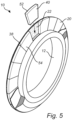
- the shape of the wear pads 40 are as shown in figure 5 , i.e. they could have been envisaged as wedges which have been radially cut from a ring.
- the wear pads have a cutting edge 52 which will be in contact with the rock and a mounting part 54 which will join to the disc body 12 and may be either spherically or conically shaped at its largest diameter.
- the number of wear pads 40 used would be optimised for the given size of the disc cutter and for the specific application.
- Figure 5 shows one embodiment, wherein the wear pads 40 are arranged such that the neighbouring side 38 of adjacent wear pads 40 are in contact with each other. Consequently, during the HIP process bonds are formed between the adjacent wear pads 40, thus forming a continuous cutting edge.
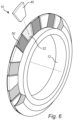
- Figure 6 shows an alternative, wherein gaps 50 could be left between each of the adjacent wear pads 40, thus forming a segmented cutting edge to create point loading effects on the rock as the cutting disc rotates.
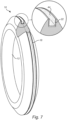
- Figure 7 shows the disc body is formed with a circumferal grove 44 formed the peripheral edge 18 to construct the disc cutter.
- the intermetallic layer 22 placed the circumferal grove 44 in the disc body 12 and / or on the mounting part 54 of each of the wear pads 40.
- the wear pads 40 may be inserted into the circumferal grove 44 formed in the disc body 12.
- recesses could be formed in the peripheral edge 18 of the disc body 12 for the wear pads to be inserted into.
- the wear pads 40 could be fixed in place by inserting the wear pads 40 in-between a first layer 34 of the disc body 12 and a second layer 36 of the disc body 12, similar to that shown in figure 4 , with the buttons 26 being replaced by wear pads 40.
- the first layer 34 and second layer 36 of the disc body 12 are formed with recesses 46 to hold the wear pads 40 in place. If gaps are to be left between each of the adjacent wear pads 40 then at least one of the first layer 34 and /or second layer 36 of the disc body will be formed such that there is a volume of metal alloy or MMC to fill in the gaps and thus, post the HIP process, an integrated unit is formed. Similarly, the metallic interlayer 22 is positioned between the disc body 12 and the wear pads 40 before the HIP process.
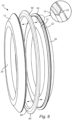
- Figure 8 shows one embodiment, wherein the at least one cutting part 20 is in the form of a continuous ring 60.
- the continuous ring is preferably made out of cemented carbide.
- the continuous ring 60 comprises a sharp peripheral cutting edge 64 and a support part 66 and may be either spherically or conically shaped at its largest diameter.
- Figure 8 shows the support part 66 is enclosed within the circumferential groove 62 of the disc body 12.
- Figures 8 and 9 shows the continuous ring 60 is fixed in place by inserting it in-between a first layer 34 of the disc body 12 and a second layer 36 of the disc body 12 with a metallic interlayer 22 positioned between the continuous ring 60 and the disc body 12.
- a cross sectional view of the metallic interlayer 22 is shown in the enlargement in figure 8 .
- At least one of the first layer 34 and/or second layer 36 are formed with a continuous recess 62 to hold the continuous ring 60 in place.
- the continuous ring 60 could also be mechanically locked into position before the HIP treatment by any other suitable method.
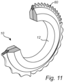
- the cross section of the continuous ring 60 could be either symmetrical, as shown in figure 10 or non-symmetrical, as shown in figure 11 .
- the resulting profile of the cutting edge may either be a smooth as shown in figure 10 or oscillating so as to form a 'cogwheel' shape as shown in figure 11.
- Figure 11 discloses different profiles of the continuous ring 60.
- the disc body 12 comprises at least two layers, each layer having a different type of metal alloy or metal matrix alloy.
- the disc cutter may comprise a first layer 34, which will form the second side 16 of the disc cutter 10 and a second layer 36, which will form the first side 14 of the disc cutter 10.
- the first layer 34 and the second layer 36 could be made from different materials, for example a higher wear resistant grade of metal alloy or MMC could be used on the side of the disc cutter 10 that is exposed to higher wear rates and the side less exposed to the wear could be made from a cheaper grade of metal alloy or MMC.
- FIG. 1 Another aspect of the present disclosure is a method for manufacturing a disc cutter 10 for a cutting unit used in tunnel boring machines comprising an annular disc body 12 made of a metal alloy or metal matrix composite having a first side 14, an second side 16 arranged substantially opposite to the first side 14 and a radially peripheral part 18; and at least one metal alloy, metal matrix composite or cemented carbide cutting part 20 mounted in and substantially encircling the radially peripheral part 18 of the disc body 12 which protrudes outwardly therefrom to engage with the rock during the cutting operation; comprising the steps of:
- Steps d) to g) above describe a Hot Isostatic Pressing (HIP) process.
- HIP is a method which is very suitable for Near Net Shape manufacturing of individual components.
- a capsule which defines the final shape of the component is filled with a metallic powder and subjected to high temperature and pressure whereby the particles of the metallic powder bond metallurgically, voids are closed and the material is consolidated.
- the main advantage of the method is that it produces components of final, or close to final, shape having strengths comparable to or better than forged material.
- the specific advantage of using a HIP method to join the at least one cutting part 20 to the disc body 12 for use as a disc cutter 10 in a tunnel boring machine is that higher wear resistance and integrity of the joints is achieved.
- Figure 12 shows a flow chart of the method.
- the diffusion bonding of the metal alloy or metal matrix composite disc body 12 and the at least one metal alloy, metal matrix composite or cemented carbide cutting part 20 occurs when the capsule is exposed to the high temperature and high pressure for certain duration of time inside a pressure vessel.
- the capsule may be a metal capsule which is sealed by means of welding. Alternatively, the capsule may be formed by a glass body.
- the disc body 12, the cutting part 20 and metallic interlayer 22 are consolidated and a diffusion bond is formed.
- the holding time has come to an end, the temperature inside the vessel and consequently also of the consolidate body is returned to room temperature. Diffusion bonds are formed by the elements of the metallic interlayer 22 and the elements of the disc body 12 and the at least one cutting part 20.
- the pre-determined temperature applied during the predetermined time may, of course, vary slightly during said period, either because of intentional control thereof or due to unintentional variation.
- the temperature should be high enough to guarantee a sufficient degree of diffusion bonding within a reasonable time period between the disc body and the at least one cutting part.
- the predetermined temperature is above about 1000 °C, such as about 1100 to about 1200°C.
- the predetermined pressure applied during said predetermined time may vary either as a result of intentional control thereof or as a result of unintentional variations thereof related to the process.
- the predetermined pressure will depend on the properties of the disc body and the at least one cutting part to be diffusion bonded.
- the time during which the elevated temperature and the elevated pressure are applied is, of course, dependent on the rate of diffusion bonding achieved with the selected temperature and pressure for a specific the disc body 12 geometry, and, of course, on the properties of the at least one cutting part 20 to be diffusion bonded.
- Predetermined time ranges are for example from 30 minutes to 10 hours.
- the at least one cutting part 20 comprises cemented carbide.
- the cemented carbide consists of a hard phase comprising titanium carbide, titanium nitride, titanium carbonitride, tantalum carbide, niobium carbide, tungsten carbide or a mixture therefore and a metallic binder phase selected from cobalt, nickel, iron or a mixture thereof.
- the disc body 12 is made of steel.
- the metallic interlayer 22 essentially comprises nickel, nickel alloy, copper or copper alloy.
- the metallic interlayer 22 is formed by an alloy essentially consisting of copper and nickel.
- the presence of the metallic interlayer 22 will avoid the formation of brittle phases such as M 6 C-phase (also known as eta-phase) and W 2 C-phase in the interface between the cemented carbide and the surrounding steel or cast iron. It is important to avoid the formation of such brittle phases as they are prone to cracking easily under load, which may cause detachment of the cemented carbide or the cracks may propagate into the cemented carbide cutting part 20 and cause these to fail with decreased wear resistance of the component as a result.
- M 6 C-phase also known as eta-phase
- W 2 C-phase W 2 C-phase
- the metallic interlayer 22 formed by an alloy essentially consisting of copper and nickel, between or on at least one of the surfaces of the disc body 12 and / or the at least one cutting part 20 that the above problem is alleviated.
- the metallic interlayer 22 acts as migration barrier or a choke for the migration of carbon atoms between the metal alloy or metal matrix alloy and cemented carbide without impairing the ductility of the diffusion bond in-between. This means that the risk that the at least one cemented carbide cutting part 20 will crack during operation and cause failure of the component is reduced.
- the metallic interlayer 20 may be formed from a foil or a powder.
- the application of the metallic interlayer 20 may also be performed by other methods such as thermal spray processes (HVOF, plasma spraying and cold spraying).
- the metallic interlayer 20 may be applied to: either the surface(s) of the disc body 12 or the surface(s) of the at least one cutting part 20; or on both the surface(s) of the disc body 12 and the at surface(s) of the at least one cutting part 20; or in between the surfaces of the disc body 12 and the at least one cutting part 20.
- HIP thermal spray processes
- the metallic interlayer 22 may alternatively be applied by electrolytic plating.
- the copper content of the metallic interlayer 22 is of from 25 to 98 wt%, preferably from 30 to 90 weight% (wt%), more preferably from 50 to 90 wt%.
- the chosen composition of the metallic interlayer 22 will depend on several parameters such as the HIP cycle plateau temperature and holding time as well as the carbon activity at that temperature of the components to be bonded.
- the metallic interlayer 22 has thickness of about 5 to about 500 ⁇ m, such as from 100 to 500 ⁇ m. If the metallic interlayer is in the form of a foil, the thickness will typically be between about 50 to about 500 ⁇ m.
- the thickness will typically be between 5 and 25 ⁇ m.
- the term "essentially consists" as used herein refers to that the metallic interlayer 22 apart from copper and nickel also may comprise other elements, though only at impurity levels, i.e. less than 3 wt%.
- Figure 13 shows one embodiment, wherein a plurality of grooves 70 are formed in the surfaces of the at least one cutting part 20 or in the surfaces of both the at least one disc body 12 and the at least one cutting part 20.
- the inclusion of the grooves 70 increases the surface area between the at least one cutting part 20 and the disc body 12 and thus improves the strength of the joint in-between.
- the grooves 70 could also be in the form of waves or ridges.
- drill holes are machined into the disc body 12 in order to be able to attach the disc cutter 10 to the tunnel boring machine (not shown).
- any of the embodiments disclosed hereinbefore or hereinafter could be combined together.
- the application of the metallic interlayer 22, comprising either: essentially nickel, nickel alloy, copper or copper alloy; or comprising an alloy essentially consisting of copper and nickel could be combined with the at least one cutting part 20 comprising cemented carbide.
- the application of the metallic interlayer 22 as described hereinbefore or hereinafter could be combined with the at least one cutting part 20 being in the form of a plurality of buttons 26 or a plurality of wear pads 40 or being in the form of a continuous cutting ring 60.
- the application of the metallic interlayer 22 as described hereinbefore or hereinafter could be combined with the disc body 12 having at least two layers.
- the at least one cutting part 20 being in the form of a plurality of buttons 26 or a plurality of wear pads 40 or being in the form of a continuous cutting ring 60 could be combined with the disc body 12 having at least two layers and / or with the at least cutting part 20 comprising cemented carbide.
- the addition of the grooves 70 which could be added to the surface(s) of the at least one cutting part 20 or to the surface(s) of both the at least one disc body 12 and to the surface(s) of the at least one cutting part 20 could be combined with the application of the metallic interlayer 22 as described hereinbefore or hereinafter.
- grooves 70 which could be added to the surface(s) of the at least one cutting part 20 or to the surface(s) of both the at least one disc body 12 and to the surface(s) of the at least one cutting part 20 could be combined with the at least one cutting part 20 being in the form of a plurality of buttons 26 or a plurality of wear pads 40 or being in the form of a continuous cutting ring 60.
Landscapes
- Engineering & Computer Science (AREA)
- Mechanical Engineering (AREA)
- Chemical & Material Sciences (AREA)
- Materials Engineering (AREA)
- Mining & Mineral Resources (AREA)
- Geology (AREA)
- Life Sciences & Earth Sciences (AREA)
- Metallurgy (AREA)
- Organic Chemistry (AREA)
- Manufacturing & Machinery (AREA)
- Environmental & Geological Engineering (AREA)
- General Life Sciences & Earth Sciences (AREA)
- Geochemistry & Mineralogy (AREA)
- Composite Materials (AREA)
- Fluid Mechanics (AREA)
- Physics & Mathematics (AREA)
- Electrochemistry (AREA)
- Chemical Kinetics & Catalysis (AREA)
- Crystallography & Structural Chemistry (AREA)
- Earth Drilling (AREA)
- Excavating Of Shafts Or Tunnels (AREA)
- Powder Metallurgy (AREA)
Priority Applications (7)
| Application Number | Priority Date | Filing Date | Title |
|---|---|---|---|
| EP18208067.1A EP3656975B1 (en) | 2018-11-23 | 2018-11-23 | Disc cutter for tunnel boring machines and a method of manufacture thereof |
| CA3114729A CA3114729A1 (en) | 2018-11-23 | 2019-10-31 | Disc cutter for tunnel boring machines and a method of manufacture thereof |
| PCT/EP2019/079755 WO2020104161A1 (en) | 2018-11-23 | 2019-10-31 | Disc cutter for tunnel boring machines and a method of manufacture thereof |
| US17/295,764 US20220018251A1 (en) | 2018-11-23 | 2019-10-31 | Disc cutter for tunnel boring machines and a method of manufacture thereof |
| JP2021529049A JP7335959B2 (ja) | 2018-11-23 | 2019-10-31 | トンネルボーリングマシン用のディスクカッター及びその製造方法 |
| CN201980068978.2A CN112930430A (zh) | 2018-11-23 | 2019-10-31 | 用于隧道掘进机的盘形刀具及其制造方法 |
| KR1020217013267A KR20210094524A (ko) | 2018-11-23 | 2019-10-31 | 터널 보링 머신용 디스크 커터 및 이의 제조 방법 |
Applications Claiming Priority (1)
| Application Number | Priority Date | Filing Date | Title |
|---|---|---|---|
| EP18208067.1A EP3656975B1 (en) | 2018-11-23 | 2018-11-23 | Disc cutter for tunnel boring machines and a method of manufacture thereof |
Publications (2)
| Publication Number | Publication Date |
|---|---|
| EP3656975A1 EP3656975A1 (en) | 2020-05-27 |
| EP3656975B1 true EP3656975B1 (en) | 2023-04-26 |
Family
ID=64456854
Family Applications (1)
| Application Number | Title | Priority Date | Filing Date |
|---|---|---|---|
| EP18208067.1A Active EP3656975B1 (en) | 2018-11-23 | 2018-11-23 | Disc cutter for tunnel boring machines and a method of manufacture thereof |
Country Status (7)
| Country | Link |
|---|---|
| US (1) | US20220018251A1 (ja) |
| EP (1) | EP3656975B1 (ja) |
| JP (1) | JP7335959B2 (ja) |
| KR (1) | KR20210094524A (ja) |
| CN (1) | CN112930430A (ja) |
| CA (1) | CA3114729A1 (ja) |
| WO (1) | WO2020104161A1 (ja) |
Families Citing this family (3)
| Publication number | Priority date | Publication date | Assignee | Title |
|---|---|---|---|---|
| WO2022227787A1 (zh) * | 2021-04-26 | 2022-11-03 | 孟小玲 | 中空回转型岩石巷道掘进机 |
| SE545894C2 (en) * | 2021-06-22 | 2024-03-05 | Sandvik Machining Solutions Ab | Method for manufacturing an article comprising cemented carbide and an inserted object |
| CN117627666A (zh) * | 2023-12-19 | 2024-03-01 | 中铁十四局集团有限公司 | 一种面向硬岩地层的长寿命盾构滚刀刀圈及其设计方法 |
Family Cites Families (17)
| Publication number | Priority date | Publication date | Assignee | Title |
|---|---|---|---|---|
| ZA744897B (en) | 1974-07-31 | 1976-05-26 | Board Hardmetal Proprietary Lt | Improvements in or relating to disc cutting units for use on rock boring machines |
| US4496372A (en) * | 1982-03-31 | 1985-01-29 | Almond Eric A | Abrasive bodies |
| US4907665A (en) * | 1984-09-27 | 1990-03-13 | Smith International, Inc. | Cast steel rock bit cutter cones having metallurgically bonded cutter inserts |
| JPS6182959A (ja) * | 1984-09-27 | 1986-04-26 | スミス インターナシヨナル、インコーポレイテツド | 冶金的に接着された硬質植材を有する鋳鋼工具及びその製造方法 |
| GB2184382B (en) * | 1985-12-23 | 1989-10-18 | Hip Ltd | Securing inserts |
| SE467700B (sv) | 1986-01-28 | 1992-08-31 | Boart Int Ltd | Skivformat skaer foer bergbearbetningsmaskiner |
| US5626201A (en) * | 1993-09-20 | 1997-05-06 | Excavation Engineering Associates, Inc. | Disc cutter and method of replacing disc cutters |
| ATE315714T1 (de) * | 2000-05-18 | 2006-02-15 | Commw Scient Ind Res Org | Schneidwerkzeug und verfahren zu dessen benutzung |
| JP2004060201A (ja) * | 2002-07-26 | 2004-02-26 | Mitsubishi Materials Corp | 高速回転操業条件ですぐれた耐微少欠け性を発揮する掘削工具の切刃片 |
| AU2007359121B2 (en) * | 2007-09-18 | 2015-05-07 | Caterpillar Global Mining Europe Gmbh | Roller drill or roller bit |
| US20120039739A1 (en) * | 2010-08-10 | 2012-02-16 | David Krauter | Cutter rings and method of manufacture |
| CN202520319U (zh) * | 2012-03-28 | 2012-11-07 | 张厚美 | 一种具有硬质合金刀刃的滚刀 |
| US9366088B2 (en) * | 2013-03-08 | 2016-06-14 | Us Synthetic Corporation | Cutter assemblies, disc cutters, and related methods of manufacture |
| CN203430522U (zh) * | 2013-07-05 | 2014-02-12 | 张洪明 | 一种盾构机滚刀刀圈 |
| JP6423218B2 (ja) * | 2014-09-22 | 2018-11-14 | 清水建設株式会社 | ローラカッター及びその製造方法 |
| US10018042B2 (en) * | 2015-10-30 | 2018-07-10 | The Robbins Company | Clamped-ring cutter assembly for tunnel boring machine |
| CN109844262B (zh) * | 2016-08-19 | 2021-07-16 | 久益环球地下采矿有限责任公司 | 切削装置及其支撑件 |
-
2018
- 2018-11-23 EP EP18208067.1A patent/EP3656975B1/en active Active
-
2019
- 2019-10-31 CA CA3114729A patent/CA3114729A1/en active Pending
- 2019-10-31 US US17/295,764 patent/US20220018251A1/en active Pending
- 2019-10-31 JP JP2021529049A patent/JP7335959B2/ja active Active
- 2019-10-31 CN CN201980068978.2A patent/CN112930430A/zh active Pending
- 2019-10-31 KR KR1020217013267A patent/KR20210094524A/ko not_active Application Discontinuation
- 2019-10-31 WO PCT/EP2019/079755 patent/WO2020104161A1/en active Application Filing
Also Published As
| Publication number | Publication date |
|---|---|
| JP7335959B2 (ja) | 2023-08-30 |
| KR20210094524A (ko) | 2021-07-29 |
| JP2022513118A (ja) | 2022-02-07 |
| WO2020104161A1 (en) | 2020-05-28 |
| US20220018251A1 (en) | 2022-01-20 |
| EP3656975A1 (en) | 2020-05-27 |
| CA3114729A1 (en) | 2020-05-28 |
| CN112930430A (zh) | 2021-06-08 |
Similar Documents
| Publication | Publication Date | Title |
|---|---|---|
| RU2429104C2 (ru) | Буровое долото для роторного бурения и способ изготовления бурового долота с корпусом из композита из связующего материала с другими частицами | |
| EP3656975B1 (en) | Disc cutter for tunnel boring machines and a method of manufacture thereof | |
| US8083012B2 (en) | Diamond bonded construction with thermally stable region | |
| CN102764893B (zh) | 具有改进的抗热开裂性的制品 | |
| US8197936B2 (en) | Cutting structures | |
| EP2609290A2 (en) | Bonding of a super-hard wear part to a tool component | |
| US11933107B2 (en) | Disc cutter for undercutting apparatus and a method of manufacture thereof | |
| CN110114176B (zh) | 工具 | |
| US9605489B2 (en) | Composite part including a cutting element | |
| AU2019385558B2 (en) | Disc cutter for undercutting apparatus and a method of manufacture thereof | |
| US10655398B2 (en) | Attachment of TSP diamond ring using brazing and mechanical locking | |
| RU2797517C2 (ru) | Дисковый нож для врубового устройства и способ его изготовления | |
| JPS61270495A (ja) | ロ−タリ・ドリル・ビツトとその製造方法 | |
| CA3062746A1 (en) | A process of manufacturing an article comprising a body of a cemented carbide and a body of a metal alloy or of a metal matrix composite, and a product manufactured thereof | |
| US20120168232A1 (en) | Localized features and manufacturing methods for inserts of rock bits | |
| JP2004291038A (ja) | 超硬合金製部材とダイヤモンド製部材との接合方法、接合構造、掘削工具の切刃片、切刃部材、及び掘削工具 | |
| JP2004291039A (ja) | 超硬合金製部材とダイヤモンド製部材との接合方法、接合構造、掘削工具の切刃片、切刃部材、及び掘削工具 |
Legal Events
| Date | Code | Title | Description |
|---|---|---|---|
| PUAI | Public reference made under article 153(3) epc to a published international application that has entered the european phase |
Free format text: ORIGINAL CODE: 0009012 |
|
| STAA | Information on the status of an ep patent application or granted ep patent |
Free format text: STATUS: THE APPLICATION HAS BEEN PUBLISHED |
|
| AK | Designated contracting states |
Kind code of ref document: A1 Designated state(s): AL AT BE BG CH CY CZ DE DK EE ES FI FR GB GR HR HU IE IS IT LI LT LU LV MC MK MT NL NO PL PT RO RS SE SI SK SM TR |
|
| AX | Request for extension of the european patent |
Extension state: BA ME |
|
| STAA | Information on the status of an ep patent application or granted ep patent |
Free format text: STATUS: REQUEST FOR EXAMINATION WAS MADE |
|
| 17P | Request for examination filed |
Effective date: 20201127 |
|
| RBV | Designated contracting states (corrected) |
Designated state(s): AL AT BE BG CH CY CZ DE DK EE ES FI FR GB GR HR HU IE IS IT LI LT LU LV MC MK MT NL NO PL PT RO RS SE SI SK SM TR |
|
| GRAJ | Information related to disapproval of communication of intention to grant by the applicant or resumption of examination proceedings by the epo deleted |
Free format text: ORIGINAL CODE: EPIDOSDIGR1 |
|
| GRAP | Despatch of communication of intention to grant a patent |
Free format text: ORIGINAL CODE: EPIDOSNIGR1 |
|
| GRAP | Despatch of communication of intention to grant a patent |
Free format text: ORIGINAL CODE: EPIDOSNIGR1 |
|
| RIC1 | Information provided on ipc code assigned before grant |
Ipc: C25D 7/00 20060101ALI20221018BHEP Ipc: C22C 29/08 20060101ALI20221018BHEP Ipc: C22C 19/00 20060101ALI20221018BHEP Ipc: C22C 9/00 20060101ALI20221018BHEP Ipc: B23K 31/02 20060101ALI20221018BHEP Ipc: B23K 20/24 20060101ALI20221018BHEP Ipc: B23K 20/227 20060101ALI20221018BHEP Ipc: B23K 20/16 20060101ALI20221018BHEP Ipc: B23K 20/02 20060101ALI20221018BHEP Ipc: B22F 7/06 20060101ALI20221018BHEP Ipc: B22F 5/10 20060101ALI20221018BHEP Ipc: B22F 3/15 20060101ALI20221018BHEP Ipc: E21B 10/12 20060101ALI20221018BHEP Ipc: E21B 10/573 20060101ALI20221018BHEP Ipc: E21D 9/10 20060101AFI20221018BHEP |
|
| STAA | Information on the status of an ep patent application or granted ep patent |
Free format text: STATUS: GRANT OF PATENT IS INTENDED |
|
| INTG | Intention to grant announced |
Effective date: 20221124 |
|
| RAP1 | Party data changed (applicant data changed or rights of an application transferred) |
Owner name: SANDVIK MINING AND CONSTRUCTION TOOLS AB |
|
| GRAS | Grant fee paid |
Free format text: ORIGINAL CODE: EPIDOSNIGR3 |
|
| GRAA | (expected) grant |
Free format text: ORIGINAL CODE: 0009210 |
|
| STAA | Information on the status of an ep patent application or granted ep patent |
Free format text: STATUS: THE PATENT HAS BEEN GRANTED |
|
| AK | Designated contracting states |
Kind code of ref document: B1 Designated state(s): AL AT BE BG CH CY CZ DE DK EE ES FI FR GB GR HR HU IE IS IT LI LT LU LV MC MK MT NL NO PL PT RO RS SE SI SK SM TR |
|
| REG | Reference to a national code |
Ref country code: GB Ref legal event code: FG4D |
|
| REG | Reference to a national code |
Ref country code: CH Ref legal event code: EP |
|
| REG | Reference to a national code |
Ref country code: DE Ref legal event code: R096 Ref document number: 602018048836 Country of ref document: DE |
|
| REG | Reference to a national code |
Ref country code: AT Ref legal event code: REF Ref document number: 1562940 Country of ref document: AT Kind code of ref document: T Effective date: 20230515 |
|
| REG | Reference to a national code |
Ref country code: IE Ref legal event code: FG4D |
|
| REG | Reference to a national code |
Ref country code: LT Ref legal event code: MG9D |
|
| REG | Reference to a national code |
Ref country code: NL Ref legal event code: MP Effective date: 20230426 |
|
| REG | Reference to a national code |
Ref country code: AT Ref legal event code: MK05 Ref document number: 1562940 Country of ref document: AT Kind code of ref document: T Effective date: 20230426 |
|
| PG25 | Lapsed in a contracting state [announced via postgrant information from national office to epo] |
Ref country code: NL Free format text: LAPSE BECAUSE OF FAILURE TO SUBMIT A TRANSLATION OF THE DESCRIPTION OR TO PAY THE FEE WITHIN THE PRESCRIBED TIME-LIMIT Effective date: 20230426 |
|
| PG25 | Lapsed in a contracting state [announced via postgrant information from national office to epo] |
Ref country code: SE Free format text: LAPSE BECAUSE OF FAILURE TO SUBMIT A TRANSLATION OF THE DESCRIPTION OR TO PAY THE FEE WITHIN THE PRESCRIBED TIME-LIMIT Effective date: 20230426 Ref country code: PT Free format text: LAPSE BECAUSE OF FAILURE TO SUBMIT A TRANSLATION OF THE DESCRIPTION OR TO PAY THE FEE WITHIN THE PRESCRIBED TIME-LIMIT Effective date: 20230828 Ref country code: NO Free format text: LAPSE BECAUSE OF FAILURE TO SUBMIT A TRANSLATION OF THE DESCRIPTION OR TO PAY THE FEE WITHIN THE PRESCRIBED TIME-LIMIT Effective date: 20230726 Ref country code: ES Free format text: LAPSE BECAUSE OF FAILURE TO SUBMIT A TRANSLATION OF THE DESCRIPTION OR TO PAY THE FEE WITHIN THE PRESCRIBED TIME-LIMIT Effective date: 20230426 Ref country code: AT Free format text: LAPSE BECAUSE OF FAILURE TO SUBMIT A TRANSLATION OF THE DESCRIPTION OR TO PAY THE FEE WITHIN THE PRESCRIBED TIME-LIMIT Effective date: 20230426 |
|
| PG25 | Lapsed in a contracting state [announced via postgrant information from national office to epo] |
Ref country code: RS Free format text: LAPSE BECAUSE OF FAILURE TO SUBMIT A TRANSLATION OF THE DESCRIPTION OR TO PAY THE FEE WITHIN THE PRESCRIBED TIME-LIMIT Effective date: 20230426 Ref country code: PL Free format text: LAPSE BECAUSE OF FAILURE TO SUBMIT A TRANSLATION OF THE DESCRIPTION OR TO PAY THE FEE WITHIN THE PRESCRIBED TIME-LIMIT Effective date: 20230426 Ref country code: LV Free format text: LAPSE BECAUSE OF FAILURE TO SUBMIT A TRANSLATION OF THE DESCRIPTION OR TO PAY THE FEE WITHIN THE PRESCRIBED TIME-LIMIT Effective date: 20230426 Ref country code: LT Free format text: LAPSE BECAUSE OF FAILURE TO SUBMIT A TRANSLATION OF THE DESCRIPTION OR TO PAY THE FEE WITHIN THE PRESCRIBED TIME-LIMIT Effective date: 20230426 Ref country code: IS Free format text: LAPSE BECAUSE OF FAILURE TO SUBMIT A TRANSLATION OF THE DESCRIPTION OR TO PAY THE FEE WITHIN THE PRESCRIBED TIME-LIMIT Effective date: 20230826 Ref country code: HR Free format text: LAPSE BECAUSE OF FAILURE TO SUBMIT A TRANSLATION OF THE DESCRIPTION OR TO PAY THE FEE WITHIN THE PRESCRIBED TIME-LIMIT Effective date: 20230426 Ref country code: GR Free format text: LAPSE BECAUSE OF FAILURE TO SUBMIT A TRANSLATION OF THE DESCRIPTION OR TO PAY THE FEE WITHIN THE PRESCRIBED TIME-LIMIT Effective date: 20230727 |
|
| PG25 | Lapsed in a contracting state [announced via postgrant information from national office to epo] |
Ref country code: FI Free format text: LAPSE BECAUSE OF FAILURE TO SUBMIT A TRANSLATION OF THE DESCRIPTION OR TO PAY THE FEE WITHIN THE PRESCRIBED TIME-LIMIT Effective date: 20230426 |
|
| PG25 | Lapsed in a contracting state [announced via postgrant information from national office to epo] |
Ref country code: SK Free format text: LAPSE BECAUSE OF FAILURE TO SUBMIT A TRANSLATION OF THE DESCRIPTION OR TO PAY THE FEE WITHIN THE PRESCRIBED TIME-LIMIT Effective date: 20230426 |
|
| REG | Reference to a national code |
Ref country code: DE Ref legal event code: R097 Ref document number: 602018048836 Country of ref document: DE |
|
| PG25 | Lapsed in a contracting state [announced via postgrant information from national office to epo] |
Ref country code: SM Free format text: LAPSE BECAUSE OF FAILURE TO SUBMIT A TRANSLATION OF THE DESCRIPTION OR TO PAY THE FEE WITHIN THE PRESCRIBED TIME-LIMIT Effective date: 20230426 Ref country code: SK Free format text: LAPSE BECAUSE OF FAILURE TO SUBMIT A TRANSLATION OF THE DESCRIPTION OR TO PAY THE FEE WITHIN THE PRESCRIBED TIME-LIMIT Effective date: 20230426 Ref country code: RO Free format text: LAPSE BECAUSE OF FAILURE TO SUBMIT A TRANSLATION OF THE DESCRIPTION OR TO PAY THE FEE WITHIN THE PRESCRIBED TIME-LIMIT Effective date: 20230426 Ref country code: EE Free format text: LAPSE BECAUSE OF FAILURE TO SUBMIT A TRANSLATION OF THE DESCRIPTION OR TO PAY THE FEE WITHIN THE PRESCRIBED TIME-LIMIT Effective date: 20230426 Ref country code: DK Free format text: LAPSE BECAUSE OF FAILURE TO SUBMIT A TRANSLATION OF THE DESCRIPTION OR TO PAY THE FEE WITHIN THE PRESCRIBED TIME-LIMIT Effective date: 20230426 Ref country code: CZ Free format text: LAPSE BECAUSE OF FAILURE TO SUBMIT A TRANSLATION OF THE DESCRIPTION OR TO PAY THE FEE WITHIN THE PRESCRIBED TIME-LIMIT Effective date: 20230426 |
|
| PGFP | Annual fee paid to national office [announced via postgrant information from national office to epo] |
Ref country code: FR Payment date: 20231024 Year of fee payment: 6 Ref country code: DE Payment date: 20231003 Year of fee payment: 6 |
|
| PLBE | No opposition filed within time limit |
Free format text: ORIGINAL CODE: 0009261 |
|
| STAA | Information on the status of an ep patent application or granted ep patent |
Free format text: STATUS: NO OPPOSITION FILED WITHIN TIME LIMIT |
|
| 26N | No opposition filed |
Effective date: 20240129 |
|
| PG25 | Lapsed in a contracting state [announced via postgrant information from national office to epo] |
Ref country code: SI Free format text: LAPSE BECAUSE OF FAILURE TO SUBMIT A TRANSLATION OF THE DESCRIPTION OR TO PAY THE FEE WITHIN THE PRESCRIBED TIME-LIMIT Effective date: 20230426 |
|
| PG25 | Lapsed in a contracting state [announced via postgrant information from national office to epo] |
Ref country code: SI Free format text: LAPSE BECAUSE OF FAILURE TO SUBMIT A TRANSLATION OF THE DESCRIPTION OR TO PAY THE FEE WITHIN THE PRESCRIBED TIME-LIMIT Effective date: 20230426 Ref country code: IT Free format text: LAPSE BECAUSE OF FAILURE TO SUBMIT A TRANSLATION OF THE DESCRIPTION OR TO PAY THE FEE WITHIN THE PRESCRIBED TIME-LIMIT Effective date: 20230426 |
|
| REG | Reference to a national code |
Ref country code: CH Ref legal event code: PL |
|
| PG25 | Lapsed in a contracting state [announced via postgrant information from national office to epo] |
Ref country code: MC Free format text: LAPSE BECAUSE OF FAILURE TO SUBMIT A TRANSLATION OF THE DESCRIPTION OR TO PAY THE FEE WITHIN THE PRESCRIBED TIME-LIMIT Effective date: 20230426 |
|
| PG25 | Lapsed in a contracting state [announced via postgrant information from national office to epo] |
Ref country code: LU Free format text: LAPSE BECAUSE OF NON-PAYMENT OF DUE FEES Effective date: 20231123 |
|
| PG25 | Lapsed in a contracting state [announced via postgrant information from national office to epo] |
Ref country code: CH Free format text: LAPSE BECAUSE OF NON-PAYMENT OF DUE FEES Effective date: 20231130 |
|
| GBPC | Gb: european patent ceased through non-payment of renewal fee |
Effective date: 20231123 |
|
| PG25 | Lapsed in a contracting state [announced via postgrant information from national office to epo] |
Ref country code: MC Free format text: LAPSE BECAUSE OF FAILURE TO SUBMIT A TRANSLATION OF THE DESCRIPTION OR TO PAY THE FEE WITHIN THE PRESCRIBED TIME-LIMIT Effective date: 20230426 Ref country code: CH Free format text: LAPSE BECAUSE OF NON-PAYMENT OF DUE FEES Effective date: 20231130 Ref country code: LU Free format text: LAPSE BECAUSE OF NON-PAYMENT OF DUE FEES Effective date: 20231123 |
|
| REG | Reference to a national code |
Ref country code: BE Ref legal event code: MM Effective date: 20231130 |