EP3656810A1 - Verfahren zur herstellung eines fenster- oder tür-hohlkammerprofiles - Google Patents
Verfahren zur herstellung eines fenster- oder tür-hohlkammerprofiles Download PDFInfo
- Publication number
- EP3656810A1 EP3656810A1 EP19208810.2A EP19208810A EP3656810A1 EP 3656810 A1 EP3656810 A1 EP 3656810A1 EP 19208810 A EP19208810 A EP 19208810A EP 3656810 A1 EP3656810 A1 EP 3656810A1
- Authority
- EP
- European Patent Office
- Prior art keywords
- structural profile
- profile
- visible side
- coating material
- painting
- Prior art date
- Legal status (The legal status is an assumption and is not a legal conclusion. Google has not performed a legal analysis and makes no representation as to the accuracy of the status listed.)
- Granted
Links
Images


Classifications
-
- B—PERFORMING OPERATIONS; TRANSPORTING
- B29—WORKING OF PLASTICS; WORKING OF SUBSTANCES IN A PLASTIC STATE IN GENERAL
- B29C—SHAPING OR JOINING OF PLASTICS; SHAPING OF MATERIAL IN A PLASTIC STATE, NOT OTHERWISE PROVIDED FOR; AFTER-TREATMENT OF THE SHAPED PRODUCTS, e.g. REPAIRING
- B29C48/00—Extrusion moulding, i.e. expressing the moulding material through a die or nozzle which imparts the desired form; Apparatus therefor
- B29C48/03—Extrusion moulding, i.e. expressing the moulding material through a die or nozzle which imparts the desired form; Apparatus therefor characterised by the shape of the extruded material at extrusion
- B29C48/12—Articles with an irregular circumference when viewed in cross-section, e.g. window profiles
-
- B—PERFORMING OPERATIONS; TRANSPORTING
- B29—WORKING OF PLASTICS; WORKING OF SUBSTANCES IN A PLASTIC STATE IN GENERAL
- B29C—SHAPING OR JOINING OF PLASTICS; SHAPING OF MATERIAL IN A PLASTIC STATE, NOT OTHERWISE PROVIDED FOR; AFTER-TREATMENT OF THE SHAPED PRODUCTS, e.g. REPAIRING
- B29C48/00—Extrusion moulding, i.e. expressing the moulding material through a die or nozzle which imparts the desired form; Apparatus therefor
- B29C48/001—Combinations of extrusion moulding with other shaping operations
- B29C48/002—Combinations of extrusion moulding with other shaping operations combined with surface shaping
-
- B—PERFORMING OPERATIONS; TRANSPORTING
- B29—WORKING OF PLASTICS; WORKING OF SUBSTANCES IN A PLASTIC STATE IN GENERAL
- B29C—SHAPING OR JOINING OF PLASTICS; SHAPING OF MATERIAL IN A PLASTIC STATE, NOT OTHERWISE PROVIDED FOR; AFTER-TREATMENT OF THE SHAPED PRODUCTS, e.g. REPAIRING
- B29C48/00—Extrusion moulding, i.e. expressing the moulding material through a die or nozzle which imparts the desired form; Apparatus therefor
- B29C48/15—Extrusion moulding, i.e. expressing the moulding material through a die or nozzle which imparts the desired form; Apparatus therefor incorporating preformed parts or layers, e.g. extrusion moulding around inserts
- B29C48/151—Coating hollow articles
-
- E—FIXED CONSTRUCTIONS
- E06—DOORS, WINDOWS, SHUTTERS, OR ROLLER BLINDS IN GENERAL; LADDERS
- E06B—FIXED OR MOVABLE CLOSURES FOR OPENINGS IN BUILDINGS, VEHICLES, FENCES OR LIKE ENCLOSURES IN GENERAL, e.g. DOORS, WINDOWS, BLINDS, GATES
- E06B3/00—Window sashes, door leaves, or like elements for closing wall or like openings; Layout of fixed or moving closures, e.g. windows in wall or like openings; Features of rigidly-mounted outer frames relating to the mounting of wing frames
- E06B3/04—Wing frames not characterised by the manner of movement
- E06B3/06—Single frames
- E06B3/08—Constructions depending on the use of specified materials
- E06B3/20—Constructions depending on the use of specified materials of plastics
- E06B3/22—Hollow frames
Definitions
- the invention relates to a method for producing a window or door hollow chamber profile, the shaping of a structural profile of the hollow chamber profile having at least one hollow chamber being carried out by means of a plastic extrusion process.
- the structural profile can be made of fiber-reinforced plastic in order to improve the mechanical load-bearing capacity and thus have certain unevenness due to reinforcing fibers located on the surface.
- the EP 2 191 090 B1 proposes to coextrude the structural profile containing reinforcing fibers with a thin surface layer which is free of reinforcing fibers.
- a disadvantage of the described methods for surface coating is that coextrusion makes the manufacturing process significantly more complex and thereby also limits the possible process speeds.
- the invention is based on the object of specifying a method for producing a window or door hollow chamber profile with the features described at the outset, with which a significant improvement can be achieved in a simple manner of the visual appearance and easier cleaning of the hollow chamber profile, while at the same time allowing high production speeds.
- the Class A surface can have a visual gloss impression of at least 10, for example at least 11 or at least 12.
- the visual gloss impression can be determined, for example, in accordance with DIN EN ISO 2813 from February 2015.
- DIN EN ISO 2813 This DIN standard describes, among other things, technical processes for determining the visual gloss impression.
- Figure 1 of the DIN standard shows visual gloss impressions 1 to 13 depending on the measured gloss units (GU) in the range from 0 to 100, which can be measured using a suitable gloss measuring device, for example the "Rhopoint IQ" device from Rhopoint Instruments Limited, St Leonards-on-Sea, UK, can be measured in different ways depending on the angle of incidence of the light source.
- GU measured gloss units
- the visual gloss impression 9 corresponds, for example, to 35 measured gloss units (GU) with a measuring angle of the measuring device (see Figure 2) of 20 °, 70 GU at 60 ° and 95 GU at 85 °.
- Figure 1 shows that the measurement method at 20 ° is particularly meaningful in the high-gloss area due to the correspondingly high sensitivity of the measured values. That means that even small changes in the visual gloss impression have large changes in the measured gloss values (GU).
- Class A surface or (used below) "Class B surface” are also used, for example, in the automotive sector and mean here in the context of the invention that a Class B surface does not meet the surface requirements for a visible side of a A door or window profile is sufficient, but a Class A surface is.
- the invention is based on the knowledge that, on the one hand, by means of a painting process, on the correspondingly treated visible side of the structural profile, the desired surface quality with regard to gloss, cleanability, resistance to dirt, etc. can be produced and, on the other hand, painting can be carried out at a much higher process speed than the known coextrusion measure. It is therefore within the scope of the invention in particular that the plastic matrix of the structural profile is free of additives which increase the visual gloss impression (e.g. chalk or the like).
- the visible side of the structural profile expediently has a Class B surface with a visual gloss impression before the painting process, which has at least 1 unit, preferably at least 2 units, for example at least 3 units, e.g. is at least 4 units below the visual gloss impression of the visible side surface after the painting process.
- This is associated with the fact that the painting process is used to sustainably compensate for unevenness on the surface of the structural profile in the area of the visible side in such a way that a substantial improvement in the surface quality is achieved and thus the transition from a Class B surface to a Class A surface. Surface can be completed.
- the coating material expediently contains color pigments, e.g. White pigments (titanium dioxide or the like), so that the application of the coating material simultaneously results in a targeted, preferably opaque, coloring of the at least one visible side of the structural profile.
- white pigments titanium dioxide or the like
- This has the advantage that the desired coloring can be realized without the entire structural profile having to be colored through as seen in cross section. This is particularly relevant in view of the fact that the white pigment titanium dioxide (as well as other color pigments commonly used here), which is often used in plastic extrusion, is comparatively expensive.
- the structural profile can be made from recycled material, for example.
- reinforcing fibers are integrated into the plastic matrix of the structural profile, as is already the case in FIG cited EP 2 191 090 B1 the case is.
- Short fibers for example glass and / or carbon and / or aramid fibers
- an average fiber length of at most 20 mm, for example at most 10 mm are particularly suitable as reinforcing fibers.
- the coating is expediently applied only to the at least one visible side of the structural profile.
- the circumferential end faces of a door or window frame to be fitted into the masonry remain unpainted, since these end faces are not visible when the door or window is installed.
- the entire outer surface of the structural profile is provided with the coating.
- the coating material is preferably applied wet to the surface of the visible side.
- the coating material has a pronounced flowability when it is applied, so that it can penetrate even the smallest recesses on the visible side and thus substantially compensate for any unevenness.
- wet painting the coating material is applied in liquid form to the corresponding surface and built up by chemical and / or physical processes (for example evaporation of a solvent) to form a homogeneous, solid surface layer.
- a powder coating should not be ruled out, however.
- the coating material can be water-based or solvent-based.
- the coating material expediently contains a polyurethane resin, a polyester resin or an epoxy resin as a binder.
- the coating material can e.g.
- the layer thickness of the fully cured paint material is e.g. 100 to 700 microns, preferably 200 to 500 microns.
- the coating material applied to the structural profile is expediently cured in a separate treatment process (e.g. by means of UV radiation).
- the structural profile is preferably extruded with the aid of PVC material.
- the painting process and possibly also the treatment process for curing the painting material expediently takes place in a continuous, in particular stationary, process, preferably online, with the extrusion of the structural profile.
- the painting process on the at least one visible side of the structural profile is combined with a lamination of a, preferably opaque, laminating film onto at least one further visible side of the structural profile. It is also expedient to compensate for unevenness on the corresponding visible side by means of the lamination film in such a way that after the lamination process it has a Class A surface with a visual gloss impression of at least 5, e.g. has at least 6, preferably at least 8.
- the visual gloss impression after lamination is preferably at least 10, for example at least 11 or at least 12.
- the corresponding visible side of the structural profile before the lamination process has a Class B surface with a visual gloss impression that is at least 1 unit , preferably at least 2 units, for example at least 3 units, for example is at least 4 units below the visual gloss impression of the visible side surface after the lamination process.
- the laminating film can be colored white or, for example, yellow, red, green or blue.
- the layer thickness of the laminating film is e.g. 100 to 700 microns, preferably 200 to 500 microns.
- the lamination can take place after painting (and if necessary curing of the painting material), but alternatively also before.
- the at least one laminating film is expediently attached to the weathered and therefore more highly stressed outside of the structural profile and the coating is applied to the inside of the structural profile.
- the reverse procedure or another combination is not excluded.
- the lamination can be done online with the extrusion, but also offline.
- the invention further relates to a window or door hollow chamber profile which is produced by means of the inventive method described above.
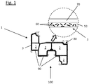
- the Fig. 1 shows a method for producing a window or door hollow chamber profile 1 for a window or door leaf frame according to the prior art.
- a plastic extrusion process is used to shape a structural profile 3 of the hollow chamber profile 1 that has a plurality of hollow chambers 2.
- the enlarged section in FIG Fig. 1 it can be seen that the structural profile 3 has a thermoplastic plastic matrix 50, into which reinforcing fibers 60 in the form of short glass fibers with an average fiber length of at most 10 mm are integrated. Because of these reinforcing fibers 60, the structural profile 3 has an outer surface with unevenness that does not meet the requirements for windows or door frames in terms of appearance, cleaning options, dirt resistance, etc.
- the structural profile 3 has been provided in the way of coextrusion with an outer coating 70 made of thermoplastic material without reinforcing fibers, which is exaggerated in the enlarged section.
- this outer coating is not applied to the entire outer surface of the structural profile 3.
- the groove base 80 of the right receiving groove and areas 90 of the underside 100 of the structural profile 3 remain uncoated.
- Fig. 2 shows an inventive window or door hollow chamber profile 1 for a window or door frame.
- a plastic extrusion process is first used to shape a structural profile 3 of the hollow chamber profile 1 which has a plurality of hollow chambers 2.
- the structural profile 3 is made from recycled PVC material M (cf. Fig. 3 ) extruded.
- the structural profile 3 can in turn also have a thermoplastic plastic matrix 50 into which Reinforcing fibers 60 in the form of short glass fibers with an average fiber length of at most 10 mm are integrated, the short glass fibers in Fig. 2
- Reinforcing fibers 60 in the form of short glass fibers with an average fiber length of at most 10 mm are integrated, the short glass fibers in Fig. 2
- the structure profile 3 thus has corresponding (not shown) bumps on its surface.
- painting material 4 is applied wetly to visible sides 5 of the structural profile 3 having two said unevenness, one visible side 5 of which is located on the weathered outer side a and another visible side 5 on the inner side i of the structural profile 3.
- the unevenness on the surface of the visible sides 5 is compensated by the painting material 4 in such a way that after the painting process they have a Class A surface with a visual gloss impression of at least 9.
- the visible sides 5 of the structural profile 3 have a Class B surface with a visual gloss impression that is at least 2 units below the visual gloss impression after the painting process.
- the wet-applied paint material 4 is then cured in a separate treatment process with UV light, so that it forms a solid coating layer on the surface of the visible sides 5. It can be seen that the lacquer 4 is only applied in a targeted manner on the two visible sides 5 of the structural profile 3 and, for example, the end face 200 of the structural profile 3 facing the masonry remains uncoated.
- the coating material 4 can contain, for example, a polyurethane resin, a polyester resin or an epoxy resin as a binder.
- the layer thickness s of the fully cured coating material 4 is 200 to 500 ⁇ m in the exemplary embodiment.
- the coating material 4 also contains (not shown in more detail) white pigments in the form of titanium dioxide particles, so that the application of the coating material 4 simultaneously results in a targeted, opaque coloring of the visible sides 5 of the structural profile 3.
- white pigments in the form of titanium dioxide particles
- Fig. 3 shows schematically a process according to the invention for producing the in Fig. 2 Hollow chamber profile 1 shown.
- an extruder E is used to produce the structural profile 3 from the PVC recyclate material M or the PVC plastic raw material M containing reinforcing fibers 60, which is then first calibrated in a calibration device K.
- the painting process in a stationary painting station L, in which case the painting material 4 is preferably applied to the structural profile 3, which is still heated by the extrusion and passes through the painting station L at the extrusion speed x, in order to connect the painting material 4 to the surface of the corresponding view pages 5 to improve.
- the coating material can be sprayed onto the visible sides 5 in the coating station L, for example by means of a pressure atomizer (not shown). Downstream of the coating, a treatment process for curing the coating material 4 with UV light UV also takes place online with the extrusion in a curing station A. The finished hollow chamber profile 1 then leaves the curing station A.
- the painting process on the visible side 5 (which is located on the inner side i) of the structural profile 3 is combined with a lamination of an opaque, white laminating film 400 onto a further visible side 5 'on the weathered outer side a of the structural profile 3.
- Unevenness on the corresponding visible side 5 ′ is also compensated for by means of the lamination film 400 in such a way that after the lamination process it has a Class A surface with a visual gloss impression of at least 9.
- the lamination film 400 has a layer thickness s K of 200 to 500 ⁇ m.
- the corresponding visible side 5 'of the structural profile 3 has a Class B surface with a visual gloss impression before the lamination process, which is at least 2 units below the visual gloss impression after the lamination process.
- the combination of coating material 4 and laminating film 400 shown can be dispensed with by adding additives (such as chalk) which increase the visual gloss impression into the raw or recycled material M of the structural profile.
- additives such as chalk
- these additives make it more difficult for the lamination film 400 to adhere to the structural profile 3, so that the method described above is also distinguished by an unproblematic lamination of the lamination film 400, which permits high process speeds.
- the Fig. 5 shows schematically the process for producing the in Fig. 4 shown hollow chamber profile 1.
- the process shown here is then, after the curing of the coating material 4 applied to the visible side 5 in the coating station L, in the curing station A additionally in a film lamination station F downstream of the curing station A in a continuous process online with the extrusion of the lamination film 400 on the visible side 5 'of the structural profile 3 applied.
- the finished hollow chamber profile 1 then leaves the film laminating station F.
- the laminating film 400 is applied in front of the coating material 4, that is to say the station F is connected upstream of the stations L and A.
Landscapes
- Engineering & Computer Science (AREA)
- Mechanical Engineering (AREA)
- Civil Engineering (AREA)
- Structural Engineering (AREA)
- Extrusion Moulding Of Plastics Or The Like (AREA)
Abstract
Description
- Die Erfindung betrifft ein Verfahren zur Herstellung eines Fenster- oder Tür-Hohlkammerprofiles, wobei im Wege eines Kunststoff-Extrusionsverfahrens die Formgebung eines mindestens eine Hohlkammer aufweisenden Strukturprofils des Hohlkammerprofils erfolgt.
- Im Stand der Technik ist es bekannt, bei der Herstellung von Kunststoffprofilen für Tür- bzw. Fensterrahmen ein extrudiertes Strukturprofil mit minderer Oberflächengüte im Wege der Coextrusion zu beschichteten, um optisch einwandfreie und gleichzeitig leicht zu reinigende Sichtoberflächen des Hohlkammerprofils zu erhalten. So kann beispielsweise das Strukturprofil zur Verbesserung der mechanischen Belastbarkeit aus faserverstärktem Kunststoff bestehen und hierdurch gewisse Unebenheiten aufgrund von an der Oberfläche befindlichen Verstärkungsfasern aufweisen. Um hier eine einwandfreie Oberfläche zu erzielen, schlägt beispielsweise die
EP 2 191 090 B1 vor, das Verstärkungsfasern enthaltende Strukturprofil mit einer dünnen Oberflächenschicht zu coextrudieren, welche frei von Verstärkungsfasern ist. - Ein weiteres großes Anwendungsgebiet, bei welchem die oben beschriebene Maßnahme ebenfalls eingesetzt wird, ist die Herstellung von Hohlkammerprofilen für Fenster und Türen mithilfe von Recyclatmaterial, da dieses in der Regel nicht über dieselbe Qualität wie beispielsweise erstmalig verarbeiteter PVC-Rohstoff verfügt.
- Nachteilig bei den beschriebenen Verfahren zur Oberflächenbeschichtung ist, dass eine Coextrusion das Fertigungsverfahren deutlich komplexer macht und dadurch auch die möglichen Prozessgeschwindigkeiten limitiert.
- Vor diesem Hintergrund liegt der Erfindung die Aufgabe zugrunde, ein Verfahren zur Herstellung eines Fenster-oder Tür-Hohlkammerprofils mit den eingangs beschriebenen Merkmalen anzugeben, mit dem sich auf einfache Weise eine signifikante Verbesserung des optischen Erscheinungsbildes sowie eine leichtere Reinigung des Hohlkammerprofils erzielen lässt und das dabei gleichzeitig hohe Produktionsgeschwindigkeiten erlaubt.
- Erfindungsgemäß wird diese Aufgabe gelöst durch ein Verfahren zur Herstellung eines Fenster- oder Tür-Hohlkammerprofiles,
- wobei im Wege eines Kunststoff-Extrusionsverfahrens die Formgebung eines mindestens eine Hohlkammer aufweisenden Strukturprofils des Hohlkammerprofils erfolgt,
- wobei danach mittels eines Lackiervorgangs Lackiermaterial auf mindestens eine Unebenheiten aufweisende Sichtseite des Strukturprofils aufgetragen wird, und
- wobei durch das Lackiermaterial die Unebenheiten an der Oberfläche der Sichtseite derart ausgeglichen werden, dass diese nach dem Lackiervorgang eine Class-A-Oberfläche mit einem visuellen Glanzeindruck von mindestens 5, z.B. mindestens 6, insbesondere mindestens 7, vorzugsweise mindestens 8 aufweist.
- Insbesondere kann nach dem Lackiervorgang die Class-A-Oberfläche einen visuellen Glanzeindruck von mindestens 10, zum Beispiel mindestens 11 oder mindestens 12 aufweisen. Der visuelle Glanzeindruck kann beispielsweise gemäß der DIN EN ISO 2813 vom Februar 2015 bestimmt werden. Diese DIN-Norm beschreibt u.a. technische Verfahren zur Bestimmung des visuellen Glanzeindrucks. In Bild 1 der DIN-Norm sind visuelle Glanzeindrücke 1 bis 13 in Abhängigkeit von gemessenen Glanzeinheiten (GU) im Bereich von 0 bis 100 dargestellt, die mittels eines geeigneten Glanzmessgerätes, beispielsweise dem Gerät "Rhopoint IQ" von der Firma Rhopoint Instruments Limited, St. Leonards-on-Sea, UK, auf unterschiedliche Weise in Abhängigkeit vom Einfallswinkel der Lichtquelle gemessen werden können. Gemäß Bild 1 entspricht der visuelle Glanzeindruck 9 beispielsweise 35 gemessenen Glanzeinheiten (GU) bei einem Messwinkel des Messgeräts (s. Bild 2) von 20°, 70 GU bei 60° und 95 GU bei 85°. Ein Glanzeindruck von 11 hingegen entspricht 64 GU bei 20°, 90 GU bei 60° und 98 GU bei 85°. Anhand Bild 1 ist erkennbar, dass insbesondere im hochglänzenden Bereich die Messmethode bei 20° aufgrund der entsprechend hohen Sensibilität der Messwerte sehr aussagekräftig ist. D.h. bereits geringe Änderungen im visuellen Glanzeindruck haben große Veränderungen bei den gemessenen Glanzwerten (GU) zufolge. Der visuelle Glanzwert, welcher von 1 = stumpf-matt bis 13 = hochglänzend reicht, kann somit gemäß der Norm mittels geeigneter Glanzmessgeräte technisch exakt bestimmt werden. Die Begriffe "Class-A-Oberfläche" bzw. (nachstehend verwendet) "Class-B-Oberfläche" sind beispielsweise auch im Automobilbereich gebräuchlich und meinen hier im Rahmen der Erfindung, dass eine Class-B-Oberfläche nicht den Oberflächenanforderungen an eine Sichtseite eines Tür- bzw. Fensterprofils genügt, eine Class-A-Oberfläche hingegen schon.
- Die Erfindung beruht auf der Erkenntnis, dass mittels eines Lackiervorgangs einerseits an der entsprechend behandelten Sichtseite des Strukturprofils die gewünschte Oberflächengüte hinsichtlich Glanz, Reinigungsfähigkeit, Schmutzunempfindlichkeit etc. hergestellt werden kann und dabei andererseits eine Lackierung mit wesentlich höherer Prozessgeschwindigkeit erfolgen kann als die bekannte Maßnahme Coextrusion. Im Rahmen der Erfindung liegt es daher insbesondere auch, dass die Kunststoff-Matrix des Strukturprofils frei von Zusatzstoffen ist, die den visuellen Glanzeindruck erhöhen (z.B. Kreide oder dergl.).
- Zweckmäßigerweise weist die Sichtseite des Strukturprofils vor dem Lackiervorgang eine Class-B-Oberfläche mit einem visuellen Glanzeindruck auf, der mindestens 1 Einheit, vorzugsweise mindestens 2 Einheiten, beispielsweise mindestens 3 Einheiten, z.B. mindestens 4 Einheiten unterhalb des visuellen Glanzeindrucks der Sichtseitenoberfläche nach dem Lackiervorgang liegt. Damit einher geht also entsprechend, dass mittels des Lackiervorgangs Unebenheiten an der Oberfläche des Strukturprofils im Bereich der Sichtseite derart nachhaltig ausgeglichen werden, dass eine substantielle Verbesserung der Oberflächengüte erreicht und somit hierdurch der Übergang von einer Class-B-Oberfläche zu einer Class-A-Oberfläche vollzogen werden kann.
- Das Lackiermaterial enthält zweckmäßigerweise Farbpigmente, z.B. Weißpigmente (Titandioxid oder dergl.), so dass durch den Auftrag des Lackiermaterials gleichzeitig eine gezielte, vorzugsweise blickdichte, Einfärbung der mindestens einen Sichtseite des Strukturprofils erfolgt. Dies hat den Vorteil, dass die gewünschte Farbgebung realisiert werden kann, ohne dass das gesamte Strukturprofil im Querschnitt gesehen entsprechend durchgefärbt werden muss. Dies ist insbesondere vor dem Hintergrund relevant, dass das in der Kunststoffextrusion häufig eingesetzte Weißpigment Titandioxid (sowie auch andere hier üblicherweise eingesetzte Farbpigmente) vergleichsweise teuer ist.
- Das Strukturprofil kann z.B. aus Recyclat-Material hergestellt werden. Alternativ oder auch ergänzend liegt es ebenso im Rahmen der Erfindung, dass in die Kunststoff-Matrix des Strukturprofils Verstärkungsfasern integriert sind, so wie dies beispielsweise in der schon zitierten
EP 2 191 090 B1 der Fall ist. Als Verstärkungsfasern kommen insbesondere Kurzfasern (bspw. Glas- und/oder Kohlenstoff- und/oder Aramidfasern) mit einer durchschnittlichen Faserlänge von maximal 20 mm, z.B. maximal 10 mm infrage. - Zweckmäßigerweise wird die Lackierung lediglich an der mindestens einen Sichtseite des Strukturprofils aufgebracht. So können z.B. insbesondere die ins Mauerwerk einzupassenden umlaufenden Stirnseiten eines Tür- oder Fensterblendrahmens unlackiert bleiben, da diese Stirnseiten im eingebauten Zustand der Tür bzw. des Fensters nicht sichtbar sind. Im Rahmen der Erfindung liegt es jedoch auch, dass die gesamte äußere Oberfläche des Strukturprofils mit der Lackierung versehen wird.
- Vorzugsweise wird das Lackiermaterial nass auf die Oberfläche der Sichtseite aufgetragenen. Hierdurch besitzt das Lackiermaterial bei seiner Applikation eine ausgeprägte Fließfähigkeit, so dass es auch in kleinste Vertiefungen der Sichtseite eindringen und damit entsprechende Unebenheiten substanziell ausgleichen kann. Beim Nasslackieren wird das Lackiermaterial in flüssiger Form auf die entsprechende Oberfläche aufgetragen und durch chemische und/oder physikalische Vorgänge (beispielsweise Verdampfen eines Lösungsmittels) zu einer homogenen, festen Oberflächenschicht aufgebaut. Eine Pulverlackierung soll hierdurch jedoch nicht ausgeschlossen sein. Das Lackiermaterial kann wasserbasiert oder aber auch lösungsmittelbasiert sein. Zweckmäßigerweise enthält das Lackiermaterial als Bindemittel ein Polyurethanharz, ein Polyesterharz oder ein Epoxidharz. Das Lackiermaterial kann z.B. auf die Sichtseite aufgespritzt oder aufgesprüht werden, beispielsweise mittels Druckzerstäuber. Im Rahmen der Erfindung liegt jedoch auch eine Tauchlackierung. Die Schichtstärke des fertig ausgehärteten Lackiermaterials beträgt z.B. 100 bis 700 µm, vorzugsweise 200 bis 500 µm. Zweckmäßigerweise wird das auf das Strukturprofil aufgetragene Lackiermaterial in einem separaten Behandlungsvorgang ausgehärtet (z.B. mittels UV-Strahlung).
- Grundsätzlich können verschiedenste Kunststoffe zur Extrusion des Strukturprofils eingesetzt werden. Vorzugsweise wird das Strukturprofil jedoch mit Hilfe von PVC-Material extrudiert.
- Zweckmäßigerweise erfolgt der Lackiervorgang und ggf. auch der Behandlungsvorgang zur Aushärtung des Lackiermaterials in einem kontinuierlichen, insbesondere stationären Prozess, vorzugsweise online mit der Extrusion des Strukturprofils.
- Im Rahmen der Erfindung liegt es ferner auch, dass der Lackiervorgang an der mindestens einen Sichtseite des Strukturprofils mit einer Aufkaschierung einer, vorzugsweise blickdichten, Kaschierfolie auf mindestens eine weitere Sichtseite des Strukturprofils kombiniert wird. Zweckmäßigerweise werden auch mittels der Kaschierfolie Unebenheiten an der entsprechenden Sichtseite derart ausgeglichen, dass diese nach dem Kaschiervorgang eine Class-A-Oberfläche mit einem visuellen Glanzeindruck von mindestens 5, z.B. mindestens 6, vorzugsweise mindestens 8, aufweist. Vorzugsweise beträgt der visuelle Glanzeindruck nach der Kaschierung mindestens 10, zum Beispiel mindestens 11 oder mindestens 12. Auch hier gilt wiederum vorzugsweise, dass die entsprechende Sichtseite des Strukturprofils vor dem Kaschiervorgang eine Class-B-Oberfläche mit einem visuellen Glanzeindruck aufweist, der mindestens 1 Einheit, vorzugsweise mindestens 2 Einheiten, beispielsweise mindestens 3 Einheiten, z.B. mindestens 4 Einheiten unterhalb des visuellen Glanzeindrucks der Sichtseitenoberfläche nach dem Kaschiervorgang liegt. Die Kaschierfolie kann weiß oder aber auch beispielsweise gelb, rot, grün oder blau eingefärbt sein. Die Schichtstärke der Kaschierfolie beträgt z.B. 100 bis 700 µm, vorzugsweise 200 bis 500 µm. Ein Vorteil der Kombination von Lackierung und Kaschierung liegt auch darin, dass aufgrund der Lackierung von Sichtseiten, die nicht mit einer Kaschierfolie versehen werden, eine Zugabe von den visuellen Glanzeindruck erhöhenden Mitteln in das Rohmaterial des Strukturprofils entbehrlich ist. Diese Mittel erschweren bekanntermaßen die Haftung von Kaschierfolien auf dem Strukturprofil. Die Kaschierung kann nach der Lackierung (und ggf. Aushärtung des Lackiermaterials) erfolgen, alternativ aber auch davor. Zweckmäßigerweise wird die mindestens eine Kaschierfolie an der bewitterten und daher höher beanspruchten Außenseite des Strukturprofils angebracht und die Lackierung an der Innenseite des Strukturprofils aufgetragen. Die umgekehrte Vorgehensweise oder aber auch eine anderweitige Kombination werden hierdurch jedoch nicht ausgeschlossen. Die Kaschierung kann online mit der Extrusion erfolgen, aber auch offline.
- Gegenstand der Erfindung ist ferner ein Fenster- oder Tür-Hohlkammerprofil, welches mittels des vorstehend beschriebenen, erfindungsgemäßen Verfahrens hergestellt wird.
- Im Folgenden wird die Erfindung anhand einer lediglich ein Ausführungsbeispiel darstellenden Zeichnung erläutert. Es zeigen schematisch:
- Fig. 1
- ein gemäß dem Stand der Technik hergestelltes Hohlkammerprofil,
- Fig. 2
- ein erfindungsgemäß hergestelltes Hohlkammerprofil,
- Fig. 3
- ein erfindungsgemäßes Herstellungsverfahren zur Herstellung des in
Fig. 2 dargestellten Hohlkammerprofils, - Fig. 4
- eine alternative Ausführungsform der Erfindung in einer der
Fig. 2 entsprechenden Darstellung und - Fig. 5
- ein erfindungsgemäßes Herstellungsverfahren zur Herstellung des in
Fig. 4 dargestellten Hohlkammerprofils. - Die
Fig. 1 zeigt ein Verfahren zur Herstellung eines Fenster- oder Tür-Hohlkammerprofiles 1 für einen Fenster- oder Türflügelrahmen gemäß dem Stand der Technik. Im Wege eines Kunststoff-Extrusionsverfahrens erfolgt die Formgebung eines mehrere Hohlkammern 2 aufweisenden Strukturprofils 3 des Hohlkammerprofils 1. Anhand des vergrößerten Ausschnitts in derFig. 1 ist erkennbar, dass das Strukturprofil 3 eine thermoplastische Kunststoff-Matrix 50 aufweist, in die Verstärkungsfasern 60 in Form von Kurzglasfasern mit einer durchschnittlichen Faserlänge von maximal 10 mm integriert sind. Aufgrund dieser Verstärkungsfasern 60 weist das Strukturprofil 3 eine äußere Oberfläche mit Unebenheiten auf, die den Anforderungen an Fenster oder Türrahmen hinsichtlich Optik, Reinigungsmöglichkeiten, Schmutzunempfindlichkeit etc. nicht entspricht. Aus diesem Grund ist beim Stand der Technik gemäßFigur 1 das Strukturprofil 3 im Wege der Coextrusion mit einer - im vergrößerten Ausschnitt übertrieben dargestellten - äußeren Beschichtung 70 aus thermoplastischem Kunststoff ohne Verstärkungsfasern versehen worden. Diese äußere Beschichtung wird jedoch nicht auf die gesamte äußere Oberfläche des Strukturprofils 3 aufgetragen. So bleiben z.B. der Nutgrund 80 der rechten Aufnahmenut ebenso wie Bereiche 90 der Unterseite 100 des Strukturprofils 3 unbeschichtet. -
Fig. 2 zeigt ein erfindungsgemäß hergestelltes Fenster- oder Tür-Hohlkammerprofil 1 für einen Fenster- oder Türblendrahmen. Auch hier erfolgt im Wege eines Kunststoff-Extrusionsverfahrens zunächst die Formgebung eines mehrere Hohlkammern 2 aufweisenden Strukturprofils 3 des Hohlkammerprofils 1. Im Ausführungsbeispiel wird das Strukturprofil 3 aus PVC-Recyclat-Material M (vergl.Fig. 3 ) extrudiert. Alternativ hierzu kann das Strukturprofil 3 auch wiederum eine thermoplastische Kunststoff-Matrix 50 aufweisen, in die Verstärkungsfasern 60 in Form von Kurzglasfasern mit einer durchschnittlichen Faserlänge von maximal 10 mm integriert sind, wobei die Kurzglasfasern inFig. 2 jedoch nicht näher dargestellt sind und insoweit auf dieFig. 1 verwiesen wird. Das Strukturprofil 3 weist somit entsprechende (nicht näher dargestellte) Unebenheiten an seiner Oberfläche auf. Danach wird mittels eines Lackiervorgangs Lackiermaterial 4 nass auf zwei besagte Unebenheiten aufweisende Sichtseiten 5 des Strukturprofils 3 aufgetragen, wobei sich hiervon eine Sichtseite 5 an der bewitterten Außenseite a und eine weitere Sichtseite 5 an der Innenseite i des Strukturprofils 3 befindet. Durch das Lackiermaterial 4 werden die Unebenheiten an der Oberfläche der Sichtseiten 5 derart ausgeglichen, dass diese nach dem Lackiervorgang eine Class-A-Oberfläche mit einem visuellen Glanzeindruck von mindestens 9 aufweisen. Vor dem Lackiervorgang weisen die Sichtseiten 5 des Strukturprofils 3 hingegen eine Class-B-Oberfläche mit einem visuellen Glanzeindruck auf, der mindestens 2 Einheiten unterhalb des visuellen Glanzeindrucks nach dem Lackiervorgang liegt. Das nass aufgetragene Lackiermaterial 4 wird anschließend in einem separaten Behandlungsvorgang mit UV-Licht ausgehärtet, so dass es auf der Oberfläche der Sichtseiten 5 eine feste Überzugsschicht bildet. Es ist erkennbar, dass die Lackierung 4 lediglich gezielt an den beiden Sichtseiten 5 des Strukturprofils 3 aufgebracht wird und z.B. die dem Mauerwerk zugewandte Stirnseite 200 des Strukturprofils 3 unbeschichtet bleibt. Das Lackiermaterial 4 kann als Bindemittel beispielsweise ein Polyurethanharz, ein Polyesterharz oder ein Epoxidharz enthalten. Die Schichtstärke s des fertig ausgehärteten Lackiermaterials 4 beträgt im Ausführungsbeispiel 200 bis 500 µm. - Das Lackiermaterial 4 enthält ferner (nicht näher dargestellte) Weißpigmente in Form von Titandioxid-Partikeln, so dass durch den Auftrag des Lackiermaterials 4 gleichzeitig eine gezielte blickdichte Einfärbung der Sichtseiten 5 des Strukturprofils 3 erfolgt. Dies hat den Vorteil, dass die gewünschte Farbgebung realisiert werden kann, ohne dass das gesamte Strukturprofil 3 im Querschnitt gesehen entsprechend durchgefärbt werden muss. Dies ist insbesondere vor dem Hintergrund relevant, dass das in der Kunststoffextrusion häufig eingesetzte Weißpigment Titandioxid vergleichsweise teuer ist.
-
Fig. 3 zeigt schematisch einen erfindungsgemäßen Prozess zur Herstellung des inFig. 2 gezeigten Hohlkammerprofils 1. Es ist erkennbar, dass mittels eines Extruders E aus dem PVC-Recyclatmaterial M bzw. dem Verstärkungsfasern 60 enthaltenden PVC-Kunststoff-Rohmaterial M das Strukturprofil 3 hergestellt wird, welches danach zunächst in einer Kalibriervorrichtung K kalibriert wird. Hieran anschließend erfolgt online mit der Extrusion, also in einem ebenfalls kontinuierlichen Prozess der Lackiervorgang in einer stationären Lackierstation L, wobei hier das Lackiermaterial 4 vorzugsweise auf das noch durch die Extrusion erwärmte, mit der Extrusionsgeschwindigkeit x die Lackierstation L durchlaufende Strukturprofil 3 aufgetragen wird, um die Anbindung des Lackiermaterials 4 an die Oberfläche der entsprechenden Sichtsteiten 5 zu verbessern. Das Lackiermaterial kann in der Lackierstation L z.B. mittels eines (nicht dargestellten) Druckzerstäubers auf die Sichtseiten 5 aufgesprüht werden. Der Lackierung nachgeschaltet erfolgt in einem kontinuierlichen Prozess ebenfalls online mit der Extrusion in einer Aushärtungsstation A ein Behandlungsvorgang zur Aushärtung des Lackiermaterials 4 mit UV-Licht UV. Sodann verlässt das fertig hergestellte Hohlkammerprofil 1 die Aushärtungsstation A. - Beim Ausführungsbeispiel gemäß
Fig. 4 wird der Lackiervorgang an der Sichtseite 5 (welche sich an der Innenseite i befindet) des Strukturprofils 3 mit einer Aufkaschierung einer blickdichten, weißen Kaschierfolie 400 auf eine weitere Sichtseite 5' an der bewitterten Außenseite a des Strukturprofils 3 kombiniert. Auch mittels der Kaschierfolie 400 werden Unebenheiten an der entsprechenden Sichtseite 5' derart ausgeglichen, dass diese nach dem Kaschiervorgang eine Class-A-Oberfläche mit einem visuellen Glanzeindruck von mindestens 9 aufweist. Die Kaschierfolie 400 weist eine Schichtstärke sK von 200 bis 500 µm auf. Und auch hier gilt, dass die entsprechende Sichtseite 5' des Strukturprofils 3 vor dem Kaschiervorgang eine Class-B-Oberfläche mit einem visuellen Glanzeindruck aufweist, der mindestens 2 Einheiten unterhalb des visuellen Glanzeindrucks nach dem Kaschiervorgang liegt. Durch die inFig. 4 dargestellte Kombination von Lackiermaterial 4 und Kaschierfolie 400 kann von einer Zugabe von den visuellen Glanzeindruck erhöhenden Zusatzstoffen (z.B. Kreide) in das Roh- bzw. Recyclat-Material M des Strukturprofils Abstand genommen werden. Diese Zusatzstoffe erschweren bekanntermaßen die Haftung der Kaschierfolie 400 auf dem Strukturprofil 3, so dass sich das vorbeschriebene Verfahren auch durch eine unproblematische Aufkaschierung der Kaschierfolie 400 auszeichnet, die hohe Prozessgeschwindigkeiten erlaubt. - Die
Fig. 5 zeigt schematisch den Prozess zur Herstellung des inFig. 4 gezeigten Hohlkammerprofils 1. Im Vergleich zum inFig. 3 dargestellten Prozess wird hier anschließend an die Aushärtung des - in der Lackierstation L auf die Sichtseite 5 aufgetragenen - Lackiermaterials 4 in der Aushärtungsstation A zusätzlich in einer der Aushärtungsstation A nachgeschalteten Folienkaschierstation F in einem kontinuierlichen Verfahren online mit der Extrusion die Kaschierfolie 400 auf die Sichtseite 5' des Strukturprofils 3 aufgetragen. - Anschließend verlässt das fertig hergestellte Hohlkammerprofil 1 die Folienkaschierstation F. Im Rahmen der Erfindung liegt es allerdings auch, dass die Kaschierfolie 400 vor dem Lackiermaterial 4 aufgetragen wird, also die Station F den Stationen L und A vorgeschaltet ist.
Claims (15)
- Verfahren zur Herstellung eines Fenster- oder Tür-Hohlkammerprofiles (1),- wobei im Wege eines Kunststoff-Extrusionsverfahrens die Formgebung eines mindestens eine Hohlkammer (2) aufweisenden Strukturprofils (3) des Hohlkammerprofils (1) erfolgt,- wobei danach mittels eines Lackiervorgangs Lackiermaterial (4) auf mindestens eine Unebenheiten aufweisende Sichtseite (5) des Strukturprofils (3) aufgetragen wird, und- wobei durch das Lackiermaterial (4) die Unebenheiten an der Oberfläche der Sichtseite (5) derart ausgeglichen werden, dass diese nach dem Lackiervorgang eine Class-A-Oberfläche mit einem visuellen Glanzeindruck von mindestens 5, z.B. mindestens 6, vorzugsweise mindestens 8, aufweist.
- Verfahren nach Anspruch 1, dadurch gekennzeichnet, dass die Kunststoff-Matrix (50) des Strukturprofils (3) frei von Zusatzstoffen ist, die den visuellen Glanzeindruck erhöhen.
- Verfahren nach Anspruch 1 oder 2, dadurch gekennzeichnet, dass die Sichtseite (5) des Strukturprofils (3) vor dem Lackiervorgang eine Class-B-Oberfläche mit einem visuellen Glanzeindruck aufweist, der mindestens 1 Einheit, vorzugsweise mindestens 2 Einheiten unterhalb des visuellen Glanzeindrucks nach dem Lackiervorgang liegt.
- Verfahren nach einem der Ansprüche 1 bis 3, dadurch gekennzeichnet, dass das Lackiermaterial (4) Farbpigmente enthält, so dass durch den Auftrag der Lackierschicht (4) gleichzeitig eine, vorzugsweise blickdichte, Einfärbung der mindestens einen Sichtseite (5) des Strukturprofils (3) erfolgt.
- Verfahren nach Anspruch 4, dadurch gekennzeichnet, dass als Farbpigmente Weißpigmente, insbesondere Titandioxid-Partikel verwendet werden.
- Verfahren nach einem der Ansprüche 1 bis 5, dadurch gekennzeichnet, dass das Strukturprofil (3) aus Recyclat-Material hergestellt wird.
- Verfahren nach einem der Ansprüche 1 bis 6, dadurch gekennzeichnet, dass in die Kunststoff-Matrix des Strukturprofils (3) Verstärkungsfasern, insbesondere Kurzfasern mit einer durchschnittlichen Faserlänge von maximal 20 mm, integriert sind.
- Verfahren nach einem der Ansprüche 1 bis 7, dadurch gekennzeichnet, dass das Lackiermaterial (4) lediglich an der mindestens einen Sichtseite (5) des Strukturprofils (3) aufgebracht wird.
- Verfahren nach einer der Ansprüche 1 bis 8, dadurch gekennzeichnet, dass das Lackiermaterial (4) nass auf die Oberfläche der Sichtseite (5) aufgetragenen wird.
- Verfahren nach einem der Ansprüche 1 bis 9, dadurch gekennzeichnet, dass das Lackiermaterial (4) als Bindemittel ein Polyurethanharz, ein Polyesterharz oder ein Epoxidharz enthält.
- Verfahren nach einem der Ansprüche 1 bis 10, dadurch gekennzeichnet, dass die Schichtstärke (s) des Lackiermaterials (4) 200 bis 500 µm beträgt.
- Verfahren nach einem der Ansprüche 1 bis 11, dadurch gekennzeichnet, dass das auf das Strukturprofil (3) aufgetragene Lackiermaterial (4) in einem separaten Behandlungsvorgang ausgehärtet wird.
- Verfahren nach einem der Ansprüche 1 bis 12, dadurch gekennzeichnet, dass der Lackiervorgang und ggf. der Behandlungsvorgang zur Aushärtung des Lackiermaterials (4) in einem kontinuierlichen Prozess, vorzugsweise online mit der Extrusion des Strukturprofils (3) erfolgt.
- Verfahren nach einem der Ansprüche 1 bis 13, dadurch gekennzeichnet, dass der Lackiervorgang an der mindestens einen Sichtseite (5) des Strukturprofils (3) mit einer Aufkaschierung einer, vorzugsweise blickdichten, Kaschierfolie (400) auf mindestens eine weitere Sichtseite (5') des Strukturprofils (3) kombiniert wird.
- Fenster- oder Tür-Hohlkammerprofil (1) hergestellt mit einem Verfahren nach einem der Ansprüche 1 bis 14.
Applications Claiming Priority (1)
| Application Number | Priority Date | Filing Date | Title |
|---|---|---|---|
| DE102018129558.8A DE102018129558A1 (de) | 2018-11-23 | 2018-11-23 | Verfahren zur Herstellung eines Fenster- oder Tür-Hohlkammerprofiles |
Publications (2)
| Publication Number | Publication Date |
|---|---|
| EP3656810A1 true EP3656810A1 (de) | 2020-05-27 |
| EP3656810B1 EP3656810B1 (de) | 2021-06-16 |
Family
ID=68581377
Family Applications (1)
| Application Number | Title | Priority Date | Filing Date |
|---|---|---|---|
| EP19208810.2A Active EP3656810B1 (de) | 2018-11-23 | 2019-11-13 | Verfahren zur herstellung eines fenster- oder tür-hohlkammerprofiles |
Country Status (2)
| Country | Link |
|---|---|
| EP (1) | EP3656810B1 (de) |
| DE (1) | DE102018129558A1 (de) |
Families Citing this family (1)
| Publication number | Priority date | Publication date | Assignee | Title |
|---|---|---|---|---|
| DE202024101372U1 (de) | 2024-03-19 | 2025-06-26 | REHAU Industries SE & Co. KG | Verbundprofil sowie dieses umfassender Fenster- oder Türrahmen |
Citations (4)
| Publication number | Priority date | Publication date | Assignee | Title |
|---|---|---|---|---|
| DE102007004229A1 (de) * | 2007-01-27 | 2008-07-31 | Rehau Ag + Co | Dekorierbares Kunststoffprofil und Verfahren zu dessen Herstellung |
| DE102011076959A1 (de) * | 2011-06-06 | 2012-12-06 | Kunststoff-Technik Scherer & Trier Gmbh & Co. Kg | Verfahren zur Herstellung eines zumindest abschnittsweise lackierten Kunststoffteils, Kunststoffteil sowie Grundkörper für dessen Herstellung |
| EP2191090B1 (de) | 2007-08-17 | 2014-12-24 | Rehau AG + Co | Tür- oder Fenster-Rahmenbaugruppe aus Kunststoff-Extrudat und faserverstärktem Co-Extrudat |
| DE102013107746A1 (de) * | 2013-07-19 | 2015-01-22 | Vogler GmbH | Verfahren zum Lackieren von Kunststoff-Fensterprofilen oder daraus gebildeten Fenstern oder Türen |
-
2018
- 2018-11-23 DE DE102018129558.8A patent/DE102018129558A1/de not_active Withdrawn
-
2019
- 2019-11-13 EP EP19208810.2A patent/EP3656810B1/de active Active
Patent Citations (4)
| Publication number | Priority date | Publication date | Assignee | Title |
|---|---|---|---|---|
| DE102007004229A1 (de) * | 2007-01-27 | 2008-07-31 | Rehau Ag + Co | Dekorierbares Kunststoffprofil und Verfahren zu dessen Herstellung |
| EP2191090B1 (de) | 2007-08-17 | 2014-12-24 | Rehau AG + Co | Tür- oder Fenster-Rahmenbaugruppe aus Kunststoff-Extrudat und faserverstärktem Co-Extrudat |
| DE102011076959A1 (de) * | 2011-06-06 | 2012-12-06 | Kunststoff-Technik Scherer & Trier Gmbh & Co. Kg | Verfahren zur Herstellung eines zumindest abschnittsweise lackierten Kunststoffteils, Kunststoffteil sowie Grundkörper für dessen Herstellung |
| DE102013107746A1 (de) * | 2013-07-19 | 2015-01-22 | Vogler GmbH | Verfahren zum Lackieren von Kunststoff-Fensterprofilen oder daraus gebildeten Fenstern oder Türen |
Also Published As
| Publication number | Publication date |
|---|---|
| EP3656810B1 (de) | 2021-06-16 |
| DE102018129558A1 (de) | 2020-05-28 |
Similar Documents
| Publication | Publication Date | Title |
|---|---|---|
| EP3529062B1 (de) | Verfahren zur herstellung eines thermoplastischen fenster- oder tür-hohlkammerprofils | |
| EP3010648B1 (de) | Verfahren zur herstellung eines direkt bedruckten paneels | |
| DE102013100588A1 (de) | Hohlkammerprofil für Fenster oder Türen | |
| EP4392238A1 (de) | Verfahren zur herstellung eines polymeren, insbesondere thermoplastischen fenster- oder tür-hohlkammerprofils | |
| EP3766660B1 (de) | Kunststoffelement, herstellvorrichtung und verfahren zum herstellen des kunststoffelements | |
| EP3338993A1 (de) | Verfahren zur herstellung eines bedruckten wpc-formteils | |
| DE102016107789B4 (de) | Formteil, insbesondere als Formteil ausgebildetes Dekorteil und/oder Verkleidungsteil für einen Fahrzeuginnenraum und ein Verfahren zum Herstellen eines Formteils | |
| EP2642058A2 (de) | Verfahren zur Herstellung eines Profilverbunds und Profilverbund | |
| EP3889385A1 (de) | Profil für ein fenster- und/oder türteil mit metalllage mit faserlage | |
| DE102018129568A1 (de) | Verfahren zur Herstellung eines Fenster- oder Tür-Hohlkammerprofiles | |
| EP3656810B1 (de) | Verfahren zur herstellung eines fenster- oder tür-hohlkammerprofiles | |
| EP1423299A1 (de) | Farb- und/oder effektgebende folien, verfahren zu ihrer herstellung und ihre verwendung | |
| WO2008089967A1 (de) | Dekorierbares kunststoffprofil und verfahren zu dessen herstellung | |
| DE102018129565A1 (de) | Verfahren zur Herstellung eines Fenster- oder Tür-Hohlkammerprofiles | |
| WO2011079961A1 (de) | Formhaut und verfahren zur herstellung einer formhaut | |
| DE102016119765A1 (de) | Verfahren zur Herstellung eines thermoplastischen Strangprofils | |
| EP3587096A1 (de) | Fahrzeugaussenflächenbauteil und verfahren zum herstellen eines fahrzeugaussenflächenbauteils | |
| EP4522423A1 (de) | Verfahren zur herstellung eines profilkörpers | |
| EP1812675B1 (de) | Hohlkammerprofil aus thermoplastischem kunststoff | |
| DE10306358A1 (de) | Farb- und/oder Effekt gebende, deckende Folien zur Beschichtung von dreidimensionalen Substraten, deren Herstellung und deren Verwendung | |
| EP4561842A1 (de) | Verfahren zur herstellung eines profilkörpers | |
| DE102010006909B4 (de) | Balg als Teil eines Übergangs zwischen zwei gelenkig miteinander verbundenen Fahrzeugen, Verfahren zur Herstellung einer Stoffbahn für einen Balg sowie Verfahren zur Herstellung eines Balges | |
| EP3162843A1 (de) | Farbiges oberflächenmaterial und hiermit versehener gegenstand | |
| EP3318711A1 (de) | Verfahren zur herstellung von kunststofffenstern | |
| DE10242396B3 (de) | Bauteil |
Legal Events
| Date | Code | Title | Description |
|---|---|---|---|
| PUAI | Public reference made under article 153(3) epc to a published international application that has entered the european phase |
Free format text: ORIGINAL CODE: 0009012 |
|
| STAA | Information on the status of an ep patent application or granted ep patent |
Free format text: STATUS: THE APPLICATION HAS BEEN PUBLISHED |
|
| AK | Designated contracting states |
Kind code of ref document: A1 Designated state(s): AL AT BE BG CH CY CZ DE DK EE ES FI FR GB GR HR HU IE IS IT LI LT LU LV MC MK MT NL NO PL PT RO RS SE SI SK SM TR |
|
| AX | Request for extension of the european patent |
Extension state: BA ME |
|
| STAA | Information on the status of an ep patent application or granted ep patent |
Free format text: STATUS: REQUEST FOR EXAMINATION WAS MADE |
|
| 17P | Request for examination filed |
Effective date: 20200928 |
|
| RBV | Designated contracting states (corrected) |
Designated state(s): AL AT BE BG CH CY CZ DE DK EE ES FI FR GB GR HR HU IE IS IT LI LT LU LV MC MK MT NL NO PL PT RO RS SE SI SK SM TR |
|
| RAP1 | Party data changed (applicant data changed or rights of an application transferred) |
Owner name: REHAU AG + CO |
|
| RIC1 | Information provided on ipc code assigned before grant |
Ipc: C08J 7/04 20200101AFI20201222BHEP |
|
| GRAP | Despatch of communication of intention to grant a patent |
Free format text: ORIGINAL CODE: EPIDOSNIGR1 |
|
| STAA | Information on the status of an ep patent application or granted ep patent |
Free format text: STATUS: GRANT OF PATENT IS INTENDED |
|
| INTG | Intention to grant announced |
Effective date: 20210210 |
|
| GRAS | Grant fee paid |
Free format text: ORIGINAL CODE: EPIDOSNIGR3 |
|
| GRAA | (expected) grant |
Free format text: ORIGINAL CODE: 0009210 |
|
| STAA | Information on the status of an ep patent application or granted ep patent |
Free format text: STATUS: THE PATENT HAS BEEN GRANTED |
|
| AK | Designated contracting states |
Kind code of ref document: B1 Designated state(s): AL AT BE BG CH CY CZ DE DK EE ES FI FR GB GR HR HU IE IS IT LI LT LU LV MC MK MT NL NO PL PT RO RS SE SI SK SM TR |
|
| REG | Reference to a national code |
Ref country code: GB Ref legal event code: FG4D Free format text: NOT ENGLISH |
|
| REG | Reference to a national code |
Ref country code: CH Ref legal event code: EP |
|
| REG | Reference to a national code |
Ref country code: DE Ref legal event code: R096 Ref document number: 502019001636 Country of ref document: DE |
|
| REG | Reference to a national code |
Ref country code: AT Ref legal event code: REF Ref document number: 1402315 Country of ref document: AT Kind code of ref document: T Effective date: 20210715 |
|
| REG | Reference to a national code |
Ref country code: IE Ref legal event code: FG4D Free format text: LANGUAGE OF EP DOCUMENT: GERMAN |
|
| REG | Reference to a national code |
Ref country code: LT Ref legal event code: MG9D |
|
| PG25 | Lapsed in a contracting state [announced via postgrant information from national office to epo] |
Ref country code: FI Free format text: LAPSE BECAUSE OF FAILURE TO SUBMIT A TRANSLATION OF THE DESCRIPTION OR TO PAY THE FEE WITHIN THE PRESCRIBED TIME-LIMIT Effective date: 20210616 Ref country code: HR Free format text: LAPSE BECAUSE OF FAILURE TO SUBMIT A TRANSLATION OF THE DESCRIPTION OR TO PAY THE FEE WITHIN THE PRESCRIBED TIME-LIMIT Effective date: 20210616 Ref country code: LT Free format text: LAPSE BECAUSE OF FAILURE TO SUBMIT A TRANSLATION OF THE DESCRIPTION OR TO PAY THE FEE WITHIN THE PRESCRIBED TIME-LIMIT Effective date: 20210616 Ref country code: BG Free format text: LAPSE BECAUSE OF FAILURE TO SUBMIT A TRANSLATION OF THE DESCRIPTION OR TO PAY THE FEE WITHIN THE PRESCRIBED TIME-LIMIT Effective date: 20210916 |
|
| REG | Reference to a national code |
Ref country code: NL Ref legal event code: MP Effective date: 20210616 |
|
| PG25 | Lapsed in a contracting state [announced via postgrant information from national office to epo] |
Ref country code: GR Free format text: LAPSE BECAUSE OF FAILURE TO SUBMIT A TRANSLATION OF THE DESCRIPTION OR TO PAY THE FEE WITHIN THE PRESCRIBED TIME-LIMIT Effective date: 20210917 Ref country code: LV Free format text: LAPSE BECAUSE OF FAILURE TO SUBMIT A TRANSLATION OF THE DESCRIPTION OR TO PAY THE FEE WITHIN THE PRESCRIBED TIME-LIMIT Effective date: 20210616 Ref country code: NO Free format text: LAPSE BECAUSE OF FAILURE TO SUBMIT A TRANSLATION OF THE DESCRIPTION OR TO PAY THE FEE WITHIN THE PRESCRIBED TIME-LIMIT Effective date: 20210916 Ref country code: SE Free format text: LAPSE BECAUSE OF FAILURE TO SUBMIT A TRANSLATION OF THE DESCRIPTION OR TO PAY THE FEE WITHIN THE PRESCRIBED TIME-LIMIT Effective date: 20210616 Ref country code: RS Free format text: LAPSE BECAUSE OF FAILURE TO SUBMIT A TRANSLATION OF THE DESCRIPTION OR TO PAY THE FEE WITHIN THE PRESCRIBED TIME-LIMIT Effective date: 20210616 |
|
| PG25 | Lapsed in a contracting state [announced via postgrant information from national office to epo] |
Ref country code: EE Free format text: LAPSE BECAUSE OF FAILURE TO SUBMIT A TRANSLATION OF THE DESCRIPTION OR TO PAY THE FEE WITHIN THE PRESCRIBED TIME-LIMIT Effective date: 20210616 Ref country code: ES Free format text: LAPSE BECAUSE OF FAILURE TO SUBMIT A TRANSLATION OF THE DESCRIPTION OR TO PAY THE FEE WITHIN THE PRESCRIBED TIME-LIMIT Effective date: 20210616 Ref country code: SK Free format text: LAPSE BECAUSE OF FAILURE TO SUBMIT A TRANSLATION OF THE DESCRIPTION OR TO PAY THE FEE WITHIN THE PRESCRIBED TIME-LIMIT Effective date: 20210616 Ref country code: CZ Free format text: LAPSE BECAUSE OF FAILURE TO SUBMIT A TRANSLATION OF THE DESCRIPTION OR TO PAY THE FEE WITHIN THE PRESCRIBED TIME-LIMIT Effective date: 20210616 Ref country code: PT Free format text: LAPSE BECAUSE OF FAILURE TO SUBMIT A TRANSLATION OF THE DESCRIPTION OR TO PAY THE FEE WITHIN THE PRESCRIBED TIME-LIMIT Effective date: 20211018 Ref country code: RO Free format text: LAPSE BECAUSE OF FAILURE TO SUBMIT A TRANSLATION OF THE DESCRIPTION OR TO PAY THE FEE WITHIN THE PRESCRIBED TIME-LIMIT Effective date: 20210616 Ref country code: NL Free format text: LAPSE BECAUSE OF FAILURE TO SUBMIT A TRANSLATION OF THE DESCRIPTION OR TO PAY THE FEE WITHIN THE PRESCRIBED TIME-LIMIT Effective date: 20210616 Ref country code: SM Free format text: LAPSE BECAUSE OF FAILURE TO SUBMIT A TRANSLATION OF THE DESCRIPTION OR TO PAY THE FEE WITHIN THE PRESCRIBED TIME-LIMIT Effective date: 20210616 |
|
| PG25 | Lapsed in a contracting state [announced via postgrant information from national office to epo] |
Ref country code: PL Free format text: LAPSE BECAUSE OF FAILURE TO SUBMIT A TRANSLATION OF THE DESCRIPTION OR TO PAY THE FEE WITHIN THE PRESCRIBED TIME-LIMIT Effective date: 20210616 |
|
| REG | Reference to a national code |
Ref country code: DE Ref legal event code: R081 Ref document number: 502019001636 Country of ref document: DE Owner name: REHAU INDUSTRIES SE & CO. KG, DE Free format text: FORMER OWNER: REHAU AG + CO, 95111 REHAU, DE |
|
| REG | Reference to a national code |
Ref country code: DE Ref legal event code: R097 Ref document number: 502019001636 Country of ref document: DE |
|
| PLBE | No opposition filed within time limit |
Free format text: ORIGINAL CODE: 0009261 |
|
| STAA | Information on the status of an ep patent application or granted ep patent |
Free format text: STATUS: NO OPPOSITION FILED WITHIN TIME LIMIT |
|
| PG25 | Lapsed in a contracting state [announced via postgrant information from national office to epo] |
Ref country code: DK Free format text: LAPSE BECAUSE OF FAILURE TO SUBMIT A TRANSLATION OF THE DESCRIPTION OR TO PAY THE FEE WITHIN THE PRESCRIBED TIME-LIMIT Effective date: 20210616 |
|
| 26N | No opposition filed |
Effective date: 20220317 |
|
| PG25 | Lapsed in a contracting state [announced via postgrant information from national office to epo] |
Ref country code: AL Free format text: LAPSE BECAUSE OF FAILURE TO SUBMIT A TRANSLATION OF THE DESCRIPTION OR TO PAY THE FEE WITHIN THE PRESCRIBED TIME-LIMIT Effective date: 20210616 |
|
| REG | Reference to a national code |
Ref country code: GB Ref legal event code: 732E Free format text: REGISTERED BETWEEN 20220505 AND 20220512 |
|
| REG | Reference to a national code |
Ref country code: AT Ref legal event code: PC Ref document number: 1402315 Country of ref document: AT Kind code of ref document: T Owner name: REHAU INDUSTRIES SE & CO. KG, DE Effective date: 20220419 |
|
| REG | Reference to a national code |
Ref country code: BE Ref legal event code: PD Owner name: REHAU INDUSTRIES SE & CO. KG; DE Free format text: DETAILS ASSIGNMENT: CHANGE OF OWNER(S), OTHER; FORMER OWNER NAME: REHAU AG + CO Effective date: 20220414 |
|
| PG25 | Lapsed in a contracting state [announced via postgrant information from national office to epo] |
Ref country code: MC Free format text: LAPSE BECAUSE OF FAILURE TO SUBMIT A TRANSLATION OF THE DESCRIPTION OR TO PAY THE FEE WITHIN THE PRESCRIBED TIME-LIMIT Effective date: 20210616 |
|
| PG25 | Lapsed in a contracting state [announced via postgrant information from national office to epo] |
Ref country code: LU Free format text: LAPSE BECAUSE OF NON-PAYMENT OF DUE FEES Effective date: 20211113 Ref country code: IT Free format text: LAPSE BECAUSE OF FAILURE TO SUBMIT A TRANSLATION OF THE DESCRIPTION OR TO PAY THE FEE WITHIN THE PRESCRIBED TIME-LIMIT Effective date: 20210616 |
|
| PG25 | Lapsed in a contracting state [announced via postgrant information from national office to epo] |
Ref country code: IE Free format text: LAPSE BECAUSE OF NON-PAYMENT OF DUE FEES Effective date: 20211113 |
|
| PG25 | Lapsed in a contracting state [announced via postgrant information from national office to epo] |
Ref country code: CY Free format text: LAPSE BECAUSE OF FAILURE TO SUBMIT A TRANSLATION OF THE DESCRIPTION OR TO PAY THE FEE WITHIN THE PRESCRIBED TIME-LIMIT Effective date: 20210616 |
|
| PG25 | Lapsed in a contracting state [announced via postgrant information from national office to epo] |
Ref country code: HU Free format text: LAPSE BECAUSE OF FAILURE TO SUBMIT A TRANSLATION OF THE DESCRIPTION OR TO PAY THE FEE WITHIN THE PRESCRIBED TIME-LIMIT; INVALID AB INITIO Effective date: 20191113 |
|
| PG25 | Lapsed in a contracting state [announced via postgrant information from national office to epo] |
Ref country code: MK Free format text: LAPSE BECAUSE OF FAILURE TO SUBMIT A TRANSLATION OF THE DESCRIPTION OR TO PAY THE FEE WITHIN THE PRESCRIBED TIME-LIMIT Effective date: 20210616 |
|
| PG25 | Lapsed in a contracting state [announced via postgrant information from national office to epo] |
Ref country code: TR Free format text: LAPSE BECAUSE OF FAILURE TO SUBMIT A TRANSLATION OF THE DESCRIPTION OR TO PAY THE FEE WITHIN THE PRESCRIBED TIME-LIMIT Effective date: 20210616 |
|
| PG25 | Lapsed in a contracting state [announced via postgrant information from national office to epo] |
Ref country code: MT Free format text: LAPSE BECAUSE OF FAILURE TO SUBMIT A TRANSLATION OF THE DESCRIPTION OR TO PAY THE FEE WITHIN THE PRESCRIBED TIME-LIMIT Effective date: 20210616 |
|
| REG | Reference to a national code |
Ref country code: CH Ref legal event code: U11 Free format text: ST27 STATUS EVENT CODE: U-0-0-U10-U11 (AS PROVIDED BY THE NATIONAL OFFICE) Effective date: 20251201 |
|
| PGFP | Annual fee paid to national office [announced via postgrant information from national office to epo] |
Ref country code: DE Payment date: 20251130 Year of fee payment: 7 |
|
| PGFP | Annual fee paid to national office [announced via postgrant information from national office to epo] |
Ref country code: GB Payment date: 20251028 Year of fee payment: 7 |
|
| PGFP | Annual fee paid to national office [announced via postgrant information from national office to epo] |
Ref country code: AT Payment date: 20251016 Year of fee payment: 7 |
|
| PGFP | Annual fee paid to national office [announced via postgrant information from national office to epo] |
Ref country code: FR Payment date: 20251111 Year of fee payment: 7 |
|
| PGFP | Annual fee paid to national office [announced via postgrant information from national office to epo] |
Ref country code: BE Payment date: 20251016 Year of fee payment: 7 |
|
| PGFP | Annual fee paid to national office [announced via postgrant information from national office to epo] |
Ref country code: CH Payment date: 20251201 Year of fee payment: 7 |