EP3655797B1 - Vorrichtung und verfahren zur erkennung und korrektur von blockaden bei einem fahrzeugradarsensor - Google Patents
Vorrichtung und verfahren zur erkennung und korrektur von blockaden bei einem fahrzeugradarsensor Download PDFInfo
- Publication number
- EP3655797B1 EP3655797B1 EP18749219.4A EP18749219A EP3655797B1 EP 3655797 B1 EP3655797 B1 EP 3655797B1 EP 18749219 A EP18749219 A EP 18749219A EP 3655797 B1 EP3655797 B1 EP 3655797B1
- Authority
- EP
- European Patent Office
- Prior art keywords
- clutter
- radar
- sweeps
- signals
- digital data
- Prior art date
- Legal status (The legal status is an assumption and is not a legal conclusion. Google has not performed a legal analysis and makes no representation as to the accuracy of the status listed.)
- Active
Links
Images


Classifications
-
- G—PHYSICS
- G01—MEASURING; TESTING
- G01S—RADIO DIRECTION-FINDING; RADIO NAVIGATION; DETERMINING DISTANCE OR VELOCITY BY USE OF RADIO WAVES; LOCATING OR PRESENCE-DETECTING BY USE OF THE REFLECTION OR RERADIATION OF RADIO WAVES; ANALOGOUS ARRANGEMENTS USING OTHER WAVES
- G01S7/00—Details of systems according to groups G01S13/00, G01S15/00, G01S17/00
- G01S7/02—Details of systems according to groups G01S13/00, G01S15/00, G01S17/00 of systems according to group G01S13/00
- G01S7/40—Means for monitoring or calibrating
-
- G—PHYSICS
- G01—MEASURING; TESTING
- G01S—RADIO DIRECTION-FINDING; RADIO NAVIGATION; DETERMINING DISTANCE OR VELOCITY BY USE OF RADIO WAVES; LOCATING OR PRESENCE-DETECTING BY USE OF THE REFLECTION OR RERADIATION OF RADIO WAVES; ANALOGOUS ARRANGEMENTS USING OTHER WAVES
- G01S13/00—Systems using the reflection or reradiation of radio waves, e.g. radar systems; Analogous systems using reflection or reradiation of waves whose nature or wavelength is irrelevant or unspecified
- G01S13/02—Systems using reflection of radio waves, e.g. primary radar systems; Analogous systems
- G01S13/50—Systems of measurement based on relative movement of target
- G01S13/58—Velocity or trajectory determination systems; Sense-of-movement determination systems
- G01S13/581—Velocity or trajectory determination systems; Sense-of-movement determination systems using transmission of interrupted pulse modulated waves and based upon the Doppler effect resulting from movement of targets
- G01S13/582—Velocity or trajectory determination systems; Sense-of-movement determination systems using transmission of interrupted pulse modulated waves and based upon the Doppler effect resulting from movement of targets adapted for simultaneous range and velocity measurements
-
- G—PHYSICS
- G01—MEASURING; TESTING
- G01S—RADIO DIRECTION-FINDING; RADIO NAVIGATION; DETERMINING DISTANCE OR VELOCITY BY USE OF RADIO WAVES; LOCATING OR PRESENCE-DETECTING BY USE OF THE REFLECTION OR RERADIATION OF RADIO WAVES; ANALOGOUS ARRANGEMENTS USING OTHER WAVES
- G01S13/00—Systems using the reflection or reradiation of radio waves, e.g. radar systems; Analogous systems using reflection or reradiation of waves whose nature or wavelength is irrelevant or unspecified
- G01S13/02—Systems using reflection of radio waves, e.g. primary radar systems; Analogous systems
- G01S13/50—Systems of measurement based on relative movement of target
- G01S13/58—Velocity or trajectory determination systems; Sense-of-movement determination systems
- G01S13/60—Velocity or trajectory determination systems; Sense-of-movement determination systems wherein the transmitter and receiver are mounted on the moving object, e.g. for determining ground speed, drift angle, ground track
-
- G—PHYSICS
- G01—MEASURING; TESTING
- G01S—RADIO DIRECTION-FINDING; RADIO NAVIGATION; DETERMINING DISTANCE OR VELOCITY BY USE OF RADIO WAVES; LOCATING OR PRESENCE-DETECTING BY USE OF THE REFLECTION OR RERADIATION OF RADIO WAVES; ANALOGOUS ARRANGEMENTS USING OTHER WAVES
- G01S13/00—Systems using the reflection or reradiation of radio waves, e.g. radar systems; Analogous systems using reflection or reradiation of waves whose nature or wavelength is irrelevant or unspecified
- G01S13/88—Radar or analogous systems specially adapted for specific applications
- G01S13/93—Radar or analogous systems specially adapted for specific applications for anti-collision purposes
- G01S13/931—Radar or analogous systems specially adapted for specific applications for anti-collision purposes of land vehicles
-
- G—PHYSICS
- G01—MEASURING; TESTING
- G01S—RADIO DIRECTION-FINDING; RADIO NAVIGATION; DETERMINING DISTANCE OR VELOCITY BY USE OF RADIO WAVES; LOCATING OR PRESENCE-DETECTING BY USE OF THE REFLECTION OR RERADIATION OF RADIO WAVES; ANALOGOUS ARRANGEMENTS USING OTHER WAVES
- G01S7/00—Details of systems according to groups G01S13/00, G01S15/00, G01S17/00
- G01S7/02—Details of systems according to groups G01S13/00, G01S15/00, G01S17/00 of systems according to group G01S13/00
- G01S7/40—Means for monitoring or calibrating
- G01S7/4004—Means for monitoring or calibrating of parts of a radar system
- G01S7/4026—Antenna boresight
-
- G—PHYSICS
- G01—MEASURING; TESTING
- G01S—RADIO DIRECTION-FINDING; RADIO NAVIGATION; DETERMINING DISTANCE OR VELOCITY BY USE OF RADIO WAVES; LOCATING OR PRESENCE-DETECTING BY USE OF THE REFLECTION OR RERADIATION OF RADIO WAVES; ANALOGOUS ARRANGEMENTS USING OTHER WAVES
- G01S13/00—Systems using the reflection or reradiation of radio waves, e.g. radar systems; Analogous systems using reflection or reradiation of waves whose nature or wavelength is irrelevant or unspecified
- G01S13/02—Systems using reflection of radio waves, e.g. primary radar systems; Analogous systems
- G01S13/06—Systems determining position data of a target
- G01S13/08—Systems for measuring distance only
- G01S13/32—Systems for measuring distance only using transmission of continuous waves, whether amplitude-, frequency-, or phase-modulated, or unmodulated
- G01S13/34—Systems for measuring distance only using transmission of continuous waves, whether amplitude-, frequency-, or phase-modulated, or unmodulated using transmission of continuous, frequency-modulated waves while heterodyning the received signal, or a signal derived therefrom, with a locally-generated signal related to the contemporaneously transmitted signal
- G01S13/343—Systems for measuring distance only using transmission of continuous waves, whether amplitude-, frequency-, or phase-modulated, or unmodulated using transmission of continuous, frequency-modulated waves while heterodyning the received signal, or a signal derived therefrom, with a locally-generated signal related to the contemporaneously transmitted signal using sawtooth modulation
-
- G—PHYSICS
- G01—MEASURING; TESTING
- G01S—RADIO DIRECTION-FINDING; RADIO NAVIGATION; DETERMINING DISTANCE OR VELOCITY BY USE OF RADIO WAVES; LOCATING OR PRESENCE-DETECTING BY USE OF THE REFLECTION OR RERADIATION OF RADIO WAVES; ANALOGOUS ARRANGEMENTS USING OTHER WAVES
- G01S13/00—Systems using the reflection or reradiation of radio waves, e.g. radar systems; Analogous systems using reflection or reradiation of waves whose nature or wavelength is irrelevant or unspecified
- G01S13/88—Radar or analogous systems specially adapted for specific applications
- G01S13/93—Radar or analogous systems specially adapted for specific applications for anti-collision purposes
- G01S13/931—Radar or analogous systems specially adapted for specific applications for anti-collision purposes of land vehicles
- G01S2013/9322—Radar or analogous systems specially adapted for specific applications for anti-collision purposes of land vehicles using additional data, e.g. driver condition, road state or weather data
-
- G—PHYSICS
- G01—MEASURING; TESTING
- G01S—RADIO DIRECTION-FINDING; RADIO NAVIGATION; DETERMINING DISTANCE OR VELOCITY BY USE OF RADIO WAVES; LOCATING OR PRESENCE-DETECTING BY USE OF THE REFLECTION OR RERADIATION OF RADIO WAVES; ANALOGOUS ARRANGEMENTS USING OTHER WAVES
- G01S13/00—Systems using the reflection or reradiation of radio waves, e.g. radar systems; Analogous systems using reflection or reradiation of waves whose nature or wavelength is irrelevant or unspecified
- G01S13/88—Radar or analogous systems specially adapted for specific applications
- G01S13/93—Radar or analogous systems specially adapted for specific applications for anti-collision purposes
- G01S13/931—Radar or analogous systems specially adapted for specific applications for anti-collision purposes of land vehicles
- G01S2013/9327—Sensor installation details
- G01S2013/93271—Sensor installation details in the front of the vehicles
-
- G—PHYSICS
- G01—MEASURING; TESTING
- G01S—RADIO DIRECTION-FINDING; RADIO NAVIGATION; DETERMINING DISTANCE OR VELOCITY BY USE OF RADIO WAVES; LOCATING OR PRESENCE-DETECTING BY USE OF THE REFLECTION OR RERADIATION OF RADIO WAVES; ANALOGOUS ARRANGEMENTS USING OTHER WAVES
- G01S13/00—Systems using the reflection or reradiation of radio waves, e.g. radar systems; Analogous systems using reflection or reradiation of waves whose nature or wavelength is irrelevant or unspecified
- G01S13/88—Radar or analogous systems specially adapted for specific applications
- G01S13/93—Radar or analogous systems specially adapted for specific applications for anti-collision purposes
- G01S13/931—Radar or analogous systems specially adapted for specific applications for anti-collision purposes of land vehicles
- G01S2013/9327—Sensor installation details
- G01S2013/93272—Sensor installation details in the back of the vehicles
-
- G—PHYSICS
- G01—MEASURING; TESTING
- G01S—RADIO DIRECTION-FINDING; RADIO NAVIGATION; DETERMINING DISTANCE OR VELOCITY BY USE OF RADIO WAVES; LOCATING OR PRESENCE-DETECTING BY USE OF THE REFLECTION OR RERADIATION OF RADIO WAVES; ANALOGOUS ARRANGEMENTS USING OTHER WAVES
- G01S13/00—Systems using the reflection or reradiation of radio waves, e.g. radar systems; Analogous systems using reflection or reradiation of waves whose nature or wavelength is irrelevant or unspecified
- G01S13/88—Radar or analogous systems specially adapted for specific applications
- G01S13/93—Radar or analogous systems specially adapted for specific applications for anti-collision purposes
- G01S13/931—Radar or analogous systems specially adapted for specific applications for anti-collision purposes of land vehicles
- G01S2013/9327—Sensor installation details
- G01S2013/93275—Sensor installation details in the bumper area
-
- G—PHYSICS
- G01—MEASURING; TESTING
- G01S—RADIO DIRECTION-FINDING; RADIO NAVIGATION; DETERMINING DISTANCE OR VELOCITY BY USE OF RADIO WAVES; LOCATING OR PRESENCE-DETECTING BY USE OF THE REFLECTION OR RERADIATION OF RADIO WAVES; ANALOGOUS ARRANGEMENTS USING OTHER WAVES
- G01S7/00—Details of systems according to groups G01S13/00, G01S15/00, G01S17/00
- G01S7/02—Details of systems according to groups G01S13/00, G01S15/00, G01S17/00 of systems according to group G01S13/00
- G01S7/35—Details of non-pulse systems
- G01S7/352—Receivers
- G01S7/356—Receivers involving particularities of FFT processing
-
- G—PHYSICS
- G01—MEASURING; TESTING
- G01S—RADIO DIRECTION-FINDING; RADIO NAVIGATION; DETERMINING DISTANCE OR VELOCITY BY USE OF RADIO WAVES; LOCATING OR PRESENCE-DETECTING BY USE OF THE REFLECTION OR RERADIATION OF RADIO WAVES; ANALOGOUS ARRANGEMENTS USING OTHER WAVES
- G01S7/00—Details of systems according to groups G01S13/00, G01S15/00, G01S17/00
- G01S7/02—Details of systems according to groups G01S13/00, G01S15/00, G01S17/00 of systems according to group G01S13/00
- G01S7/35—Details of non-pulse systems
- G01S7/352—Receivers
- G01S7/358—Receivers using I/Q processing
-
- G—PHYSICS
- G01—MEASURING; TESTING
- G01S—RADIO DIRECTION-FINDING; RADIO NAVIGATION; DETERMINING DISTANCE OR VELOCITY BY USE OF RADIO WAVES; LOCATING OR PRESENCE-DETECTING BY USE OF THE REFLECTION OR RERADIATION OF RADIO WAVES; ANALOGOUS ARRANGEMENTS USING OTHER WAVES
- G01S7/00—Details of systems according to groups G01S13/00, G01S15/00, G01S17/00
- G01S7/02—Details of systems according to groups G01S13/00, G01S15/00, G01S17/00 of systems according to group G01S13/00
- G01S7/40—Means for monitoring or calibrating
- G01S7/4004—Means for monitoring or calibrating of parts of a radar system
- G01S7/4039—Means for monitoring or calibrating of parts of a radar system of sensor or antenna obstruction, e.g. dirt- or ice-coating
Definitions
- the present disclosure is related to automotive radar systems and, in particular, to an apparatus and method for detecting and correcting for blockage of an automotive radar sensor.
- Declaring a sensor blockage based on the absence of radar signal processing detections is a relatively straightforward means of determining sensor blockage with minimal additional processing time or resources.
- One drawback of this approach is that it is difficult to distinguish the blocked case from the case in which there are relatively few or no objects large enough to create detections in the field of view of a sensor that is not blocked and is functioning properly. This situation can occur, for example, when the automobile in which the system is operating is passing through a desert or along a bridge or causeway surrounded by water.
- US2017/059695 discloses an automotive radar system and method wherein a plurality of range-Doppler maps for the region are generated from digital data signals, and the plurality of range-Doppler maps are averaged to generate an averaged range-Doppler map.
- DE102009032124A1 describes a method for detecting blocked state of radar device in e.g. dead angle monitoring system, of a car.
- the method involves analyzing a portion of a reception signal, and detecting blocked state of radar devices based on analysis.
- EP 2 546 676 A1 describes a system with a controller, antenna, and method for detecting obstruction and misalignment of a ground vehicle radar having an antenna configured to detect objects in a first direction.
- the system characterized as being substantially parallel to a horizontal plane about the ground vehicle, and detect objects in a second direction characterized as being toward a roadway surface proximate to the ground vehicle.
- the second direction radar return from the roadway is expected to have certain characteristics. If the characteristics are outside of a predetermined window, then obstruction and/or misalignment of the first direction and the second direction is likely, and so the radar may not reliably detect an object in the first direction, such as a vehicle in an adjacent lane.
- US6124823B describes a radar apparatus of the present invention is a radar apparatus for detecting an object around a vehicle, which comprises a transmitter section for radiating a frequency modulated, transmitted wave a receiver section for receiving a radio wave re-radiated from an object exposed to the transmitted wave. Mixing the radio wave received with part of the transmitted wave to obtain beat signals. A signal processing section for analyzing frequencies of the beat signals to detect the object around the vehicle.
- the radar apparatus is arranged to set a first threshold value and a second threshold value higher than the first threshold value as to signal levels of a frequency spectrum of the beat signals.
- the signal processing section is arranged to detect the object around the vehicle, using a beat frequency of a signal level over the second threshold value, and to compare the frequency spectrum with the first threshold value in a predetermined frequency range to determine whether there is dirt on the transmitter section or on the receiver section.
- a radar system is provided according to accompanying claim 1.
- a radar detection method is provided according to accompanying claim 5.
- Optional features are provided according to the accompanying dependent claims.
- Automotive radar is designed for active safety, and to provide a continuous level of safety, the radar must be able to detect if it is functioning according to specifications. If the radar is blocked by mud or snow or other obscurants, then the radar performance may be significantly degraded, and the user should be alerted. In some configurations, it would be desirable to include a secondary radar sensor dedicated to monitoring the physical state of the primary radar. However, due to considerations of cost and physical space, this approach is considered impractical. Therefore, according to the present disclosure, the radar system itself is configured to detect whether it is blocked and to report blockage to the user/operator. According to the present disclosure, an approach to detecting blockage, concluding whether the radar is blocked or unblocked, and reporting radar sensor blockage is described in detail.
- the exemplary radar system claimed and described in detail herein has a central frequency of approximately 24 GHz with an elevation beam width of approximately 20° FWHM (full-width half-maximum).
- the radar sensor is typically mounted about 0.5 m above the road.
- Fig. 1 includes a schematic block diagram of an automotive radar system 10 for processing automobile radar signals, in accordance with some exemplary embodiments.
- system 10 includes a radar sensor module 12, which processes radar transmit and receive signals which are compatible with the radar detection and monitoring system in the host automobile.
- Radar module 12 generates and transmits radar signals into the region adjacent to the host vehicle that is being monitored by the radar system Generation and transmission of signals is accomplished by RF signal generator 24, radar transmit circuitry 20 and transmit antenna 16.
- Radar transmit circuitry 20 generally includes any circuitry required to generate the signals transmitted via transmit antenna 16, such as pulse shaping circuitry, transmit trigger circuitry, RF switch circuitry, or any other appropriate transmit circuitry used by the radar system.
- Radar module 12 also receives returning radar signals at radar receive circuitry 22 via receive antenna 18.
- Radar receive circuitry 22 generally includes any circuitry required to process the signals received via receive antenna 18, such as pulse shaping circuitry, receive trigger circuitry, RF switch circuitry, or any other appropriate receive circuitry used by the radar system
- the received signals processed by radar receive circuitry 22 are forwarded to phase shifter circuitry 26, which generates two signals having a predetermined phase difference. These two signals, referred to as an inphase (I) signal and a quadrature (Q) signal, are mixed with an RF signal from RF signal generator 24 by mixers 28 and 30, respectively.
- the resulting difference signals are further filtered as required by filtering circuitry 32 to generate baseband I and Q signals, labeled "I” and "Q” in Fig. 1 .
- the baseband I and Q signals are digitized by analog-to-digital converter circuitry (ADC) 34.
- ADC analog-to-digital converter circuitry
- a processor 36 which can include such circuitry as a digital signal processor (DSP), associated memory, associated I/O circuitry, communication bus circuitry, and any other circuitry required for carrying out any processing functions of system 10 and/or radar sensor 12.
- DSP digital signal processor
- the radar module 12 transmits and receives radar sweeps, i.e., frequency-modulated (FM) chirps, at a rate of approximately 12 Hz.
- processor 36 can perform processing such as a fast Fourier Transform (FFT) to generate Doppler range-plus-velocity (RV) bins for each sweep, which include range, bearing and velocity information for radar detection of clutter.
- FFT fast Fourier Transform
- clutter refers to any target or physical object that may return a radar signal resulting in a radar detection.
- Doppler RV bins of radar clutter data are processed according to the detailed description herein to identify when the sensor is blocked.
- radar system 10 determines whether system 10 is detecting other automobiles and stationary objects in the region being monitored. If the radar is detecting clutter objects, e.g., other vehicles, poles, guardrails, road surface, etc., then the blockage state may be set to unblocked or clear. However, the converse is not necessarily true. That is, if the radar is not detecting clutter, it cannot necessarily be concluded that the radar is blocked. Instead, it is considered that the automobile could be in the desert scenario where there is little clutter.
- clutter objects e.g., other vehicles, poles, guardrails, road surface, etc.
- environments having little radar clutter may include a desert, or other regions such as a large parking lot with no features, a large snow-covered area, a bridge or causeway adjacent to a body of water, or a grassy landscape.
- detections of environmental clutter such as stationary ground clutter, e.g., poles, guardrails, road surface, etc.
- observations of clutter detections are analyzed to identify and distinguish the environments in which the system is operating, such that a reliable determination of sensor blockage can be generated.
- Clutter observations are analyzed using multiple approaches, and the results are fused to generate a conclusion as to whether the sensor is clear or blocked.
- detection data in the Doppler RV bins can be subjected to multiple, e.g., three, analyses.
- analyses include an immediate detection analysis, a temporal averaging analysis and an RV averaging analysis.
- the immediate detection analysis is analogous to normal radar detection processing, in which clutter detections are characterized by relatively strong radar returns. Such clutter includes a passing automobile or a ground-stationary object, such as a light pole.
- the temporal averaging analysis focuses on clutter at constant RV values, such as roadside barriers, e.g., guardrails, which have weak radar returns.
- the RV averaging analysis focuses on temporally changing clutter at indistinct ranges, such as could occur in clutter-sparse environments, such as a desert, landscapes with rolling hills, bodies of water, etc.
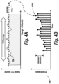
- Figs. 2 , 3 and 4 are waveform diagrams illustrating the immediate detection analysis, temporal averaging analysis and RV averaging analysis, respectively, for detection of radar sensor blockage.
- waveforms are plotted representing radar returns from successive sweeps.
- Each plotted waveform represents the FFT of an FM chirp radar sweep.
- Each plotted waveform shows radar reflective clutter as peaks positioned on the horizontal RV axis, representing the sum of the clutter object range and the clutter object velocity relative to the radar sensor, which is a known property of FM chirp radar.
- Fig. 2 which illustrates immediate detection analysis of the disclosure
- six radar returns 100a through 100g are illustrated.
- Each of the returns is compared to a clutter threshold. Where the return waveform exceeds the clutter threshold, the return is concluded to identify a clutter object.
- returns 100c and 100d are associated with a strong reflecting clutter object, which produces tall peaks in the returns, which peaks are shown to exceed their respective immediate clutter thresholds 101c and 101d.
- These strong returns result in a positive clutter indication being generated by the immediate detection analysis. Because of the positive clutter indication, it can be concluded that the sensor is not blocked.
- return waveforms 102a through 102f include no peaks tall enough to exceed their respective immediate clutter thresholds.
- the immediate detection analysis does not yield a clutter detection.
- relatively small peaks 107a through 107f, respectively, indicate a weak stationary clutter, which is largely obscured by noise.
- An example of such a stationary clutter object could be a barrier, e.g., a concrete wall along the road, which is a constant distance from the moving host vehicle.
- the temporal averaging analysis is used for such a situation to combine many radar returns, including returns 102a through 102f, from multiple respective sweeps, to produce a clear signal from the weak clutter.
- This combined signal is illustrated schematically as waveform 102g of Fig. 3 .
- the combined return 102g includes a combined peak 107g, which is more pronounced than the peaks of the individual waveforms 102a through 102f.
- the temporal averaging or combination results in better discrimination of this clutter against background noise compared to what is obtained with the immediate detection analysis by itself.
- a high variation of the averaged data across RV values, as quantified by the standard deviation, provides a positive clutter indication, and it can be concluded that the sensor is not blocked.
- Fig. 4A which illustrates temporal averaging analysis of the disclosure
- return waveform 104 changes strength as a function of time.
- An example of this situation is a landscape of gently changing radar reflectivity without distinct clutter objects at specific ranges.
- an RV interval of data for each radar sweep is averaged.
- the result of this averaging is a value 105a illustrated in Fig. 4A .
- this same value 105b is stored with a sequence of RV averages from radar sweeps at other times.
- a high temporal variation of the averages from different sweeps, as quantified by their standard deviation provides a positive clutter indication, and it can be concluded that the sensor is not blocked.
- the results of the immediate detection analysis, temporal averaging analysis and RV averaging analysis are fused to generate an overall result regarding possible blockage of the radar sensor.
- the results are logically "OR'ed” such that if any of the three analyses generates a clutter detection, then it can be concluded that the sensor is not blocked. Conversely, if none of the three analyses generates a clutter detection, then it can be concluded that the sensor is blocked.
- Fig. 5 includes a top-level logical flow diagram illustrating steps in a method of detecting radar sensor blockage, according to an exemplary embodiments.
- FM radar sweep data collection and conditioning including FFT processing is performed in step 300.
- the data for the sweeps, as illustrated and described above in connection with Figs. 3 through 5 is analyzed to generate clutter detections is step 400.
- This clutter detection processing receives the individual predetermined detection thresholds and compares the processed sweep data to the thresholds as described above.
- the results of the three analyses are logically OR'ed, such that a positive detection by any of the analyses results in a conclusion of a clutter detection.
- This OR'ed clutter result is input to blockage logic 500 to determine whether a blockage declaration should be issued.
- Fig. 6 includes a logical flow diagram of steps in FM data collection and conditioning 300 illustrated in Fig. 5 , according to some exemplary embodiments.
- the FM chirp data is received and processed at step 302, the processing including mean subtraction, I-Q calibration correction, beamforming and other data processing and conditioning.
- step 304 further processing of the FM data, including complex FFT, is performed.
- steps 302, 304 and 306 are traditional radar processing operations whose purpose is to provide Doppler radar detections.
- the operations in step 302 condition the radar data in preparation for the FFT operation in step 304.
- step 304 provide an array of bins containing complex-valued Doppler signals and convert them to real-valued Doppler detection magnitudes.
- the array of bins is indexed by the range-plus-velocity (RV) of detected clutter in the radar data, where velocities are measured radially with respect to the radar transmitter/receiver.
- RV range-plus-velocity
- step 306 weighting is performed on the data in each RV bin. In some exemplary embodiments, data from certain predetermined RV bins is emphasized by weighting, and data from other predetermined RV bins is deemphasized by weighting.
- data from low-valued RV bins are deemphasized by weighting, and data from high-valued RV bins are emphasized by weighting.
- the conditioned RV data, including weighted Doppler radar detections in an array of RV bins, is forwarded to clutter detection 400.
- Fig. 7 includes a logical flow diagram of steps in clutter detection 400 illustrated in Fig. 5 , according to some exemplary embodiments.
- the conditioned RV data is received at the three independent analyses described herein, namely, the immediate detection analysis, indicated by line 416, the temporal averaging analysis 402, and the RV averaging analysis 404.
- the sweep data at 416 is compared to the predetermined threshold, illustrated for two sweeps as 101c and 101d, in threshold comparison processing 408.
- a standard deviation of the sweep data is computed in a moving time window as data for successive sweeps is received. The standard deviation is compared to a predetermined threshold standard deviation. If the threshold is exceeded, then a clutter detection signal is issued and transmitted to OR processing 414.
- the temporal averaging analysis 402 is sensitive to small clutter signals that are unchanging over time.
- the analysis maintains temporal averaged array of clutter signals at different RV bins.
- Each new radar sweep provides signals in an array at different RV bins, which is combined with the temporal averaged array.
- each new array of signals is combined with the temporal averaged array to produce a fading-memory temporal average, and this average is preserved from one sweep to the next.
- the feedback path 403 indicates the preservation of the temporal average information from one radar sweep to the next radar sweep.
- the variation of these averages across RV bins is used to indicate the presence of a clutter object, for example, the object indicated by peaks 107a-107f in Fig. 3 .
- the RV averaging analysis 404 and 406 is sensitive to radar returns that change strength over time, even in the absence of distinctly identifiable clutter objects.
- the Doppler signals from a set of RV bins are averaged, and the averaged data 105a, referred to herein as the RV average, is observed over many sweeps to identify variations over time. Over time, these RV averages 105b are maintained in memory, referred to herein as temporal stack 406. Over time, returns for each new sweep are averaged over the set of RV bins, and the RV average is appended to the stack.
- this stack is maintained in a first-in-first-out (FIFO) configuration such that, after the stack is full at a predetermined number of sweeps, e.g., 100 sweeps, as each new sweep is received, the RV average is appended to the stack, and the RV average from the oldest sweep is removed from the stack.
- the feedback path 407 indicates the preservation of the temporal stack information from one radar sweep to the next radar sweep.
- the stack of RV averages is analyzed for temporal variability. A standard deviation measuring variability can be computed across the temporal stack and can be compared to a predetermined threshold in threshold comparison processing 412. If the threshold is exceeded, then a clutter detection signal is issued and transmitted to OR processing 414.
- OR processing 414 receives signals indicative of indications generated by immediate detection analysis, temporal averaging analysis and RV averaging analysis. If any of these indications is active/true, then OR processing generates an active/true clutter signal.
- Fig. 8 includes a logical flow diagram of steps in blockage detection logic 500 illustrated in Fig. 5 , according to some exemplary embodiments.
- the clutter signal is received at a decision block 502. If the clutter signal is low, i.e., inactive or false, then clutter is not detected, and a low count is incremented in step 506.
- a predetermined minimum number of cycles i.e., sweeps, without a clutter detection is required before a notification of sensor blockage is issued.
- decision block 510 a determination is made as to whether the minimum number of cycles without a clutter detection has been reached. In the particular exemplary embodiment illustrated in Fig. 8 , the minimum number of cycles is 100. It will be understood that other minimums can be selected. If the minimum has not been reached, then flow returns to decision block 502, where the next sweep is analyzed. If the minimum has been reached, then a sensor blockage is indicated in step 514.
- decision block 502 if the clutter signal is high, i.e., active or true, then clutter is detected, and a high count is incremented in step 504.
- a predetermined minimum number of cycles i.e., sweeps, with a clutter detection present is required before a notification of sensor non-blockage is issued.
- decision block 508 a determination is made as to whether the minimum number of cycles with a clutter detection has been reached. In the particular exemplary embodiment illustrated in Fig. 8 , the minimum number of cycles is two. It will be understood that other minimums can be selected. If the minimum has not been reached, then flow returns to decision block 502, where the next sweep is analyzed. If the minimum has been reached, then a sensor non-blockage is indicated in step 514.
- a hysteresis characteristic of the blockage and non-blockage notifications is included.
- a new notification state i.e., blockage or non-blockage
- that predetermined period of time can be set at approximately 30 seconds. Other periods of time can be used.
- a timer in hysteresis feature processing 516 checks the timer to determine whether the predetermined hysteresis time period has expired.
- Figs. 9 and 10 include timing diagrams illustrating timing of signals associated with the radar sensor blockage detection, according to some exemplary embodiments.
- Fig. 9 illustrates exemplary timing waveforms for a clutter detection signal generated according to immediate detection threshold comparison processing 408, a clutter detection signal generated according to temporal averaging threshold comparison processing 410, a clutter detection signal generated according to RV averaging threshold comparison processing 412, and the resulting "OR'ed" clutter signal from OR processing 414.
- Fig. 10 illustrates exemplary timing waveforms for the "OR'ed" clutter signal from OR processing 414, the low count generated in step 506 of Fig. 8 , the high count generated in step 504 of Fig. 8 , and the blockage notification signal generated according to the present disclosure.
- multiple averaging approaches to clutter detection are used to detect low-amplitude clutter objects that would otherwise be hidden below the detection threshold.
- the approach provides the flexibility to set thresholds independently for each approach to respond to different types of clutter. Since different averaging approaches are sensitive to different types of clutter, the independent thresholds can be raised to minimize false clutter detections in blocked situations.
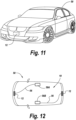
- Fig. 11 includes a schematic perspective view of an automobile 50, equipped with one or more radar systems 10, including one or more radar sensor modules 12, described herein in detail, according to exemplary embodiments.
- radar sensor module 12 is illustrated as being mounted on or in the front section of automobile 50. It will also be understood that one or more radar sensor modules 12 can be mounted at various locations on automobile 50, including at the rear of automobile 50.
- Fig. 12 includes a schematic top view of automobile 50 equipped with two radar sensor modules 12, as described above in detail, according to exemplary embodiments.
- a first radar sensor module 12 is connected via a bus 56, which in some embodiments can be a standard automotive controller area network (CAN) bus, to a first CAN bus electronic control unit (ECU) 58A. Detections generated by the processing described herein in detail in radar sensor module 12 can be reported to ECU 58A, which processes the detections and can provide detection alerts via CAN bus 56.
- a second radar sensor module 12 is connected via CAN bus 56 to a second CAN bus electronic control unit (ECU) 58B.
- ECU electronic control unit
- Detections generated by the radar processing described herein in detail in radar sensor module 12 can be reported to ECU 58B, which processes the detections and can provide detection alerts via CAN bus 56. It should be noted that this configuration is exemplary only, and that many other automobile radar system configurations within automobile 50 can be implemented. For example, a single ECU can be used instead of multiple ECUs. Also, the separate ECUs can be omitted altogether.
Landscapes
- Engineering & Computer Science (AREA)
- Radar, Positioning & Navigation (AREA)
- Remote Sensing (AREA)
- Physics & Mathematics (AREA)
- Computer Networks & Wireless Communication (AREA)
- General Physics & Mathematics (AREA)
- Electromagnetism (AREA)
- Radar Systems Or Details Thereof (AREA)
Claims (8)
- Radarsystem (10) in einem bewegbaren Host-System, wobei das Radarsystem Folgendes umfasst:einen Radardetektor (12) zum Senden von Radarsignalen in einen Bereich über eine Vielzahl von Abtastungen, Detektieren von reflektierten zurückkehrenden Radarsignalen für jede aus der Vielzahl von Abtastungen und Umwandeln der reflektierten zurückkehrenden Radarsignale in digitale Datensignale; undeinen Prozessor (36) zum Empfangen der digitalen Datensignale und Verarbeiten der digitalen Datensignale zum Detektieren von Umgebungsstörobjekten in dem Bereich,dadurch gekennzeichnet, dassdas Verarbeiten zumindest Folgendes umfasst:(i) einen unmittelbaren Detektionsvorgang, durch den die digitalen Datensignale mit einem Störungsschwellwert verglichen werden und ein erstes Signal, das das Vorliegen eines ersten Störobjekts angibt, erzeugt wird, wenn die digitalen Datensignale den Störungsschwellwert übersteigen,(ii) einen Zeitmittelungsvorgang, durch den für jeden aus einer Vielzahl von Entfernung-plus-Geschwindigkeits-(EG-)Bins Daten über mehrere Abtastungen hinweg analysiert werden, um ein zweites Signal zu erzeugen, das das Vorliegen eines zweiten Störobjekts angibt, und(iii) einen vom Zeitmittelungsvorgang unabhängigen EG-Mittelungsvorgang, durch den Daten für eine Vielzahl von EG-Werten in jeder Abtastung kombiniert werden, um EG-Mittelwerte für jede Abtastung zu bilden, und die EG-Mittelwerte für eine Vielzahl von Abtastungen über mehrere Abtastungen hinweg analysiert werden, um ein drittes Signal zu erzeugen, das das Vorliegen eines dritten Störobjekts angibt, wobeider Prozessor das erste, das zweite und das dritte Signal auf einen Logischen ODER-Vorgang anwendet, um ein viertes Signal zu erzeugen, das angibt, dass der Radardetektor nicht blockiert ist, wenn eines aus dem ersten, zweiten oder dritten Störobjekts vorliegt.
- Radarsystem (10) nach Anspruch 1, wobei das zweite und das dritte Störobjekt dasselbe Objekt sind.
- Radarsystem (10) nach Anspruch 1, wobei im Zuge des Zeitmittelungsvorganges, EG, Abweichungen eines Satzes von zeitlich gemittelten Doppler-Messungen von einer Anzahl von Abtastungen mit einem EG-Abweichungsschwellwert verglichen werden, und, wenn der EG-Abweichungsschwellwert überschritten wird, das zweite Störobjekt detektiert wird.
- Radarsystem (10) nach Anspruch 1, wobei im Zuge des EG-Mittelungsvorganges die Abweichungen eines Satzes von EG-gemittelten Abtastungen mit einem Zeitabweichungsschwellwert verglichen werden, und, wenn der Zeitabweichungsschwellwert überschritten wird, das dritte Störobjekt detektiert wird.
- Radardetektionsverfahren in einem Radardetektionssystem (10) mit bewegbarem Host, wobei das Radardetektionsverfahren Folgendes umfasst:Senden von Radarsignalen in einen Bereich über eine Vielzahl von Abtastungen;Detektieren von reflektierten zurückkehrenden Radarsignalen für jede aus der Vielzahl von Abtastungen;Umwandeln der reflektierten zurückkehrenden Radarsignale in digitale Datensignale; undVerarbeiten der digitalen Datensignale zum Detektieren von Umgebungsstörobjekten in dem Bereich,dadurch gekennzeichnet, dass das Verarbeiten Folgendes umfasst:(i) Durchführen eines unmittelbaren Detektionsvorganges, durch den die digitalen Datensignale mit einem Störungsschwellwert verglichen werden und ein erstes Signal, das das Vorliegen eines ersten Störobjekts angibt, erzeugt wird, wenn die digitalen Datensignale den Störungsschwellwert übersteigen,(ii) Durchführen eines Zeitmittelungsvorganges, durch den für jeden aus einer Vielzahl von Entfernung-plus-Geschwindigkeits-(EG-)Bins Daten über mehrere Abtastungen hinweg analysiert werden, um ein zweites Signal zu erzeugen, das das Vorliegen eines zweiten Störobjekts angibt, und(iii) Durchführen eines vom Zeitmittelungsvorgang unabhängigen EG-Mittelungsvorganges, durch den Daten für eine Vielzahl von EG-Werten in jeder Abtastung kombiniert werden, um EG-Mittelwerte für jede Abtastung zu bilden, und die EG-Mittelwerte für eine Vielzahl von Abtastungen über mehrere Abtastungen hinweg analysiert werden, um ein drittes Signal zu erzeugen, das das Vorliegen eines dritten Störobjekts angibt, undAnwenden des ersten, des zweiten und des dritten Signals auf einen Logischen ODER-Vorgang, um ein viertes Signal zu erzeugen, das angibt, dass der Radardetektor nicht blockiert ist, wenn eines aus dem ersten, zweiten oder dritten Störobjekt vorliegt.
- Verfahren nach Anspruch 5, wobei das zweite und das dritte Störobjekt dasselbe Objekt sind.
- Verfahren nach Anspruch 5, wobei im Zuge des Zeitmittelungsvorganges, EG, Abweichungen eines Satzes von zeitlich gemittelten Doppler-Messungen von einer Anzahl von Abtastungen mit einem EG-Abweichungsschwellwert verglichen werden, und, wenn der EG-Abweichungsschwellwert überschritten wird, das zweite Störobjekt detektiert wird.
- Verfahren nach Anspruch 5, wobei im Zuge des EG-Mittelungsvorganges die Abweichungen eines Satzes von EG-gemittelten Abtastungen mit einem Zeitabweichungsschwellwert verglichen werden, und, wenn der Zeitabweichungsschwellwert überschritten wird, das zweite Störobjekt detektiert wird.
Applications Claiming Priority (3)
| Application Number | Priority Date | Filing Date | Title |
|---|---|---|---|
| US201762533796P | 2017-07-18 | 2017-07-18 | |
| US15/937,026 US10794992B2 (en) | 2017-07-18 | 2018-03-27 | Apparatus and method for detecting and correcting for blockage of an automotive radar sensor |
| PCT/US2018/041802 WO2019018199A1 (en) | 2017-07-18 | 2018-07-12 | APPARATUS AND METHOD FOR DETECTING AND CORRECTING BLOCKING OF A AUTOMOTIVE RADAR SENSOR |
Publications (2)
| Publication Number | Publication Date |
|---|---|
| EP3655797A1 EP3655797A1 (de) | 2020-05-27 |
| EP3655797B1 true EP3655797B1 (de) | 2024-10-09 |
Family
ID=63077961
Family Applications (1)
| Application Number | Title | Priority Date | Filing Date |
|---|---|---|---|
| EP18749219.4A Active EP3655797B1 (de) | 2017-07-18 | 2018-07-12 | Vorrichtung und verfahren zur erkennung und korrektur von blockaden bei einem fahrzeugradarsensor |
Country Status (3)
| Country | Link |
|---|---|
| US (1) | US10794992B2 (de) |
| EP (1) | EP3655797B1 (de) |
| WO (1) | WO2019018199A1 (de) |
Families Citing this family (10)
| Publication number | Priority date | Publication date | Assignee | Title |
|---|---|---|---|---|
| US11776405B2 (en) * | 2018-10-29 | 2023-10-03 | Lg Electronics Inc. | Apparatus and method for V2X communication |
| US11280883B2 (en) | 2019-01-25 | 2022-03-22 | Veoneer Us, Inc. | Apparatus and method for detecting radar sensor blockage using machine learning |
| DE102020107804A1 (de) * | 2019-04-26 | 2020-10-29 | Infineon Technologies Ag | Radarvorrichtung und Verfahren zum Detektieren von Radarzielen |
| JP7296261B2 (ja) * | 2019-06-21 | 2023-06-22 | パナソニックホールディングス株式会社 | 監視装置、及び、監視方法 |
| JP7349277B2 (ja) * | 2019-07-10 | 2023-09-22 | ヤンマーパワーテクノロジー株式会社 | 作業車両用の自動走行システム |
| DE102019214949A1 (de) * | 2019-09-27 | 2021-04-01 | Robert Bosch Gmbh | Verfahren und Vorrichtung zum Erkennen eines absorptiven Radombelags |
| US11639984B2 (en) | 2020-05-26 | 2023-05-02 | Veoneer Us, Llc | Radar system and method using antenna correlation and covariance eigenvalues in radar sensor blockage determination |
| US20220075025A1 (en) * | 2020-09-04 | 2022-03-10 | Nuro, Inc. | Methods and Apparatus for Detecting Precipitation and Clearing Precipitation from Sensors |
| CN114779218B (zh) * | 2022-03-18 | 2025-07-29 | 深圳元戎启行科技有限公司 | 激光雷达状态检测方法、装置、计算机设备和存储介质 |
| JP7748025B2 (ja) * | 2022-03-24 | 2025-10-02 | トヨタ自動車株式会社 | レーダ装置の軸ずれのばらつき異常判定装置 |
Family Cites Families (17)
| Publication number | Priority date | Publication date | Assignee | Title |
|---|---|---|---|---|
| DE19647660B4 (de) | 1996-11-19 | 2005-09-01 | Daimlerchrysler Ag | Auslösevorrichtung für Insassenrückhaltesysteme in einem Fahrzeug |
| US5959570A (en) | 1997-11-21 | 1999-09-28 | Raytheon Company | Automotive forward looking sensor blockage detection system and related techniques |
| JP3428009B2 (ja) | 1998-07-03 | 2003-07-22 | トヨタ自動車株式会社 | 車両用レーダ装置 |
| US6469659B1 (en) | 2001-05-03 | 2002-10-22 | Delphi Technologies, Inc. | Apparatus and method for detecting radar obstruction |
| US6611227B1 (en) | 2002-08-08 | 2003-08-26 | Raytheon Company | Automotive side object detection sensor blockage detection system and related techniques |
| JP4021401B2 (ja) | 2003-11-07 | 2007-12-12 | 本田技研工業株式会社 | 車両用物体検知装置 |
| DE102004008866A1 (de) | 2004-02-20 | 2005-09-08 | Daimlerchrysler Ag | Verfahren zur Signalauswertung eines Umgebungssensors eines Kraftfahrzeuges |
| DE102005013146A1 (de) | 2005-03-22 | 2006-09-28 | Robert Bosch Gmbh | Ortungssystem mit Blindheitserkennung |
| JP5653901B2 (ja) | 2008-03-31 | 2015-01-14 | ヴァレオ・レイダー・システムズ・インコーポレーテッド | 自動車レーダ・センサ閉塞検出装置 |
| US8013781B2 (en) | 2008-09-24 | 2011-09-06 | Lockheed Martin Corporation | Method and apparatus for radar surveillance and detection of sea targets |
| DE102009001265A1 (de) | 2009-03-02 | 2010-09-09 | Robert Bosch Gmbh | Radarsensor mit Blinheitserkennungseinrichtung |
| DE102009032124B4 (de) | 2009-07-08 | 2021-02-04 | Valeo Schalter Und Sensoren Gmbh | Verfahren zum Erkennen eines blockierten Zustands eines Radargeräts und Fahrerassistenzeinrichtung |
| US8441394B2 (en) | 2011-07-11 | 2013-05-14 | Delphi Technologies, Inc. | System and method for detecting obstructions and misalignment of ground vehicle radar systems |
| US9453910B2 (en) | 2014-04-23 | 2016-09-27 | Ford Global Technologies, Llc | Detecting radar blockage based on drive history |
| US10042041B2 (en) | 2015-04-28 | 2018-08-07 | Veoneer Us, Inc. | Apparatus and method for detecting and correcting for blockage of an automotive radar sensor |
| US10054672B2 (en) | 2015-08-31 | 2018-08-21 | Veoneer Us, Inc. | Apparatus and method for detecting and correcting for blockage of an automotive radar sensor |
| US10162046B2 (en) * | 2016-03-17 | 2018-12-25 | Valeo Radar Systems, Inc. | System and method for detecting blockage in an automotive radar |
-
2018
- 2018-03-27 US US15/937,026 patent/US10794992B2/en active Active
- 2018-07-12 WO PCT/US2018/041802 patent/WO2019018199A1/en not_active Ceased
- 2018-07-12 EP EP18749219.4A patent/EP3655797B1/de active Active
Also Published As
| Publication number | Publication date |
|---|---|
| EP3655797A1 (de) | 2020-05-27 |
| WO2019018199A1 (en) | 2019-01-24 |
| US20190025404A1 (en) | 2019-01-24 |
| US10794992B2 (en) | 2020-10-06 |
Similar Documents
| Publication | Publication Date | Title |
|---|---|---|
| EP3655797B1 (de) | Vorrichtung und verfahren zur erkennung und korrektur von blockaden bei einem fahrzeugradarsensor | |
| EP3332265B1 (de) | Vorrichtung und verfahren zur erkennung der blockierung eines kraftfahrzeugradarsensors | |
| US11022675B2 (en) | Techniques for angle resolution in radar | |
| US5471214A (en) | Collision avoidance and warning system | |
| US6025796A (en) | Radar detector for pre-impact airbag triggering | |
| US9702967B2 (en) | Method for setting a detection threshold for a received signal of a frequency-modulated continuous wave radar sensor of a motor vehicle on the basis of the noise level, radar sensor and motor vehicle | |
| EP2806286B1 (de) | FMCW-Radar-Blockierungsdetektion | |
| US6469659B1 (en) | Apparatus and method for detecting radar obstruction | |
| EP0557945B1 (de) | Entfernungsmessung, Detektion und Auflösung in einem Radarsystem mit Verwendung von frequenzmodulierten Wellenformen mit mehrfachen Steilheiten | |
| EP1031851B1 (de) | Radargerät | |
| US8179303B2 (en) | Signal processing apparatus, radar apparatus, and signal processing method | |
| US9140783B2 (en) | Radar device | |
| US20170363718A1 (en) | Radar device and vertical axis-misalignment detecting method | |
| EP3256878B1 (de) | Vorrichtung und verfahren zur erkennung und korrektur von blockaden bei einem fahrzeugradarsensor | |
| WO2008055338A1 (en) | Monopulse traffic sensor and method | |
| JP2012510055A (ja) | レーダー信号処理方法およびレーダー信号処理装置 | |
| US20070040727A1 (en) | Radar device | |
| US10698105B2 (en) | Radar device and peak processing method | |
| JP2008209343A (ja) | 車載用レーダシステム | |
| JP4754292B2 (ja) | レーダ装置 | |
| EP4538734A1 (de) | Sendeleistungsregelung für radarmessung in kraftfahrzeugen | |
| Ju et al. | Development and Performance Evaluation of Integrated Automotive Mid-Range Radar System based on ROI preprocessing technique | |
| Jung et al. | Road watch radar development for obstacle detection and warning | |
| Jung et al. | Road watch radar system development |
Legal Events
| Date | Code | Title | Description |
|---|---|---|---|
| STAA | Information on the status of an ep patent application or granted ep patent |
Free format text: STATUS: UNKNOWN |
|
| STAA | Information on the status of an ep patent application or granted ep patent |
Free format text: STATUS: THE INTERNATIONAL PUBLICATION HAS BEEN MADE |
|
| PUAI | Public reference made under article 153(3) epc to a published international application that has entered the european phase |
Free format text: ORIGINAL CODE: 0009012 |
|
| STAA | Information on the status of an ep patent application or granted ep patent |
Free format text: STATUS: REQUEST FOR EXAMINATION WAS MADE |
|
| 17P | Request for examination filed |
Effective date: 20200107 |
|
| AK | Designated contracting states |
Kind code of ref document: A1 Designated state(s): AL AT BE BG CH CY CZ DE DK EE ES FI FR GB GR HR HU IE IS IT LI LT LU LV MC MK MT NL NO PL PT RO RS SE SI SK SM TR |
|
| AX | Request for extension of the european patent |
Extension state: BA ME |
|
| DAV | Request for validation of the european patent (deleted) | ||
| DAX | Request for extension of the european patent (deleted) | ||
| STAA | Information on the status of an ep patent application or granted ep patent |
Free format text: STATUS: EXAMINATION IS IN PROGRESS |
|
| 17Q | First examination report despatched |
Effective date: 20220304 |
|
| RAP3 | Party data changed (applicant data changed or rights of an application transferred) |
Owner name: VEONEER US, LLC |
|
| RAP3 | Party data changed (applicant data changed or rights of an application transferred) |
Owner name: VEONEER US, LLC |
|
| RAP3 | Party data changed (applicant data changed or rights of an application transferred) |
Owner name: MAGNA ELECTRONICS, LLC |
|
| GRAP | Despatch of communication of intention to grant a patent |
Free format text: ORIGINAL CODE: EPIDOSNIGR1 |
|
| STAA | Information on the status of an ep patent application or granted ep patent |
Free format text: STATUS: GRANT OF PATENT IS INTENDED |
|
| INTG | Intention to grant announced |
Effective date: 20240709 |
|
| RIC1 | Information provided on ipc code assigned before grant |
Ipc: G01S 7/35 20060101ALI20240628BHEP Ipc: G01S 13/34 20060101ALI20240628BHEP Ipc: G01S 13/931 20200101ALI20240628BHEP Ipc: G01S 7/40 20060101AFI20240628BHEP |
|
| GRAS | Grant fee paid |
Free format text: ORIGINAL CODE: EPIDOSNIGR3 |
|
| GRAA | (expected) grant |
Free format text: ORIGINAL CODE: 0009210 |
|
| STAA | Information on the status of an ep patent application or granted ep patent |
Free format text: STATUS: THE PATENT HAS BEEN GRANTED |
|
| AK | Designated contracting states |
Kind code of ref document: B1 Designated state(s): AL AT BE BG CH CY CZ DE DK EE ES FI FR GB GR HR HU IE IS IT LI LT LU LV MC MK MT NL NO PL PT RO RS SE SI SK SM TR |
|
| REG | Reference to a national code |
Ref country code: CH Ref legal event code: EP |
|
| REG | Reference to a national code |
Ref country code: DE Ref legal event code: R096 Ref document number: 602018075200 Country of ref document: DE |
|
| REG | Reference to a national code |
Ref country code: IE Ref legal event code: FG4D |
|
| P01 | Opt-out of the competence of the unified patent court (upc) registered |
Free format text: CASE NUMBER: APP_58958/2024 Effective date: 20241029 |
|
| REG | Reference to a national code |
Ref country code: SE Ref legal event code: TRGR |
|
| REG | Reference to a national code |
Ref country code: LT Ref legal event code: MG9D |
|
| REG | Reference to a national code |
Ref country code: NL Ref legal event code: MP Effective date: 20241009 |
|
| REG | Reference to a national code |
Ref country code: AT Ref legal event code: MK05 Ref document number: 1731132 Country of ref document: AT Kind code of ref document: T Effective date: 20241009 |
|
| PG25 | Lapsed in a contracting state [announced via postgrant information from national office to epo] |
Ref country code: NL Free format text: LAPSE BECAUSE OF FAILURE TO SUBMIT A TRANSLATION OF THE DESCRIPTION OR TO PAY THE FEE WITHIN THE PRESCRIBED TIME-LIMIT Effective date: 20241009 |
|
| PG25 | Lapsed in a contracting state [announced via postgrant information from national office to epo] |
Ref country code: NL Free format text: LAPSE BECAUSE OF FAILURE TO SUBMIT A TRANSLATION OF THE DESCRIPTION OR TO PAY THE FEE WITHIN THE PRESCRIBED TIME-LIMIT Effective date: 20241009 |
|
| PG25 | Lapsed in a contracting state [announced via postgrant information from national office to epo] |
Ref country code: IS Free format text: LAPSE BECAUSE OF FAILURE TO SUBMIT A TRANSLATION OF THE DESCRIPTION OR TO PAY THE FEE WITHIN THE PRESCRIBED TIME-LIMIT Effective date: 20250209 Ref country code: PT Free format text: LAPSE BECAUSE OF FAILURE TO SUBMIT A TRANSLATION OF THE DESCRIPTION OR TO PAY THE FEE WITHIN THE PRESCRIBED TIME-LIMIT Effective date: 20250210 Ref country code: HR Free format text: LAPSE BECAUSE OF FAILURE TO SUBMIT A TRANSLATION OF THE DESCRIPTION OR TO PAY THE FEE WITHIN THE PRESCRIBED TIME-LIMIT Effective date: 20241009 |
|
| PG25 | Lapsed in a contracting state [announced via postgrant information from national office to epo] |
Ref country code: FI Free format text: LAPSE BECAUSE OF FAILURE TO SUBMIT A TRANSLATION OF THE DESCRIPTION OR TO PAY THE FEE WITHIN THE PRESCRIBED TIME-LIMIT Effective date: 20241009 |
|
| PG25 | Lapsed in a contracting state [announced via postgrant information from national office to epo] |
Ref country code: BG Free format text: LAPSE BECAUSE OF FAILURE TO SUBMIT A TRANSLATION OF THE DESCRIPTION OR TO PAY THE FEE WITHIN THE PRESCRIBED TIME-LIMIT Effective date: 20241009 |
|
| PG25 | Lapsed in a contracting state [announced via postgrant information from national office to epo] |
Ref country code: ES Free format text: LAPSE BECAUSE OF FAILURE TO SUBMIT A TRANSLATION OF THE DESCRIPTION OR TO PAY THE FEE WITHIN THE PRESCRIBED TIME-LIMIT Effective date: 20241009 |
|
| PG25 | Lapsed in a contracting state [announced via postgrant information from national office to epo] |
Ref country code: NO Free format text: LAPSE BECAUSE OF FAILURE TO SUBMIT A TRANSLATION OF THE DESCRIPTION OR TO PAY THE FEE WITHIN THE PRESCRIBED TIME-LIMIT Effective date: 20250109 |
|
| PG25 | Lapsed in a contracting state [announced via postgrant information from national office to epo] |
Ref country code: GR Free format text: LAPSE BECAUSE OF FAILURE TO SUBMIT A TRANSLATION OF THE DESCRIPTION OR TO PAY THE FEE WITHIN THE PRESCRIBED TIME-LIMIT Effective date: 20250110 Ref country code: LV Free format text: LAPSE BECAUSE OF FAILURE TO SUBMIT A TRANSLATION OF THE DESCRIPTION OR TO PAY THE FEE WITHIN THE PRESCRIBED TIME-LIMIT Effective date: 20241009 Ref country code: AT Free format text: LAPSE BECAUSE OF FAILURE TO SUBMIT A TRANSLATION OF THE DESCRIPTION OR TO PAY THE FEE WITHIN THE PRESCRIBED TIME-LIMIT Effective date: 20241009 |
|
| PG25 | Lapsed in a contracting state [announced via postgrant information from national office to epo] |
Ref country code: PL Free format text: LAPSE BECAUSE OF FAILURE TO SUBMIT A TRANSLATION OF THE DESCRIPTION OR TO PAY THE FEE WITHIN THE PRESCRIBED TIME-LIMIT Effective date: 20241009 |
|
| PG25 | Lapsed in a contracting state [announced via postgrant information from national office to epo] |
Ref country code: RS Free format text: LAPSE BECAUSE OF FAILURE TO SUBMIT A TRANSLATION OF THE DESCRIPTION OR TO PAY THE FEE WITHIN THE PRESCRIBED TIME-LIMIT Effective date: 20250109 |
|
| PG25 | Lapsed in a contracting state [announced via postgrant information from national office to epo] |
Ref country code: SM Free format text: LAPSE BECAUSE OF FAILURE TO SUBMIT A TRANSLATION OF THE DESCRIPTION OR TO PAY THE FEE WITHIN THE PRESCRIBED TIME-LIMIT Effective date: 20241009 |
|
| PG25 | Lapsed in a contracting state [announced via postgrant information from national office to epo] |
Ref country code: DK Free format text: LAPSE BECAUSE OF FAILURE TO SUBMIT A TRANSLATION OF THE DESCRIPTION OR TO PAY THE FEE WITHIN THE PRESCRIBED TIME-LIMIT Effective date: 20241009 |
|
| REG | Reference to a national code |
Ref country code: DE Ref legal event code: R097 Ref document number: 602018075200 Country of ref document: DE |
|
| PG25 | Lapsed in a contracting state [announced via postgrant information from national office to epo] |
Ref country code: EE Free format text: LAPSE BECAUSE OF FAILURE TO SUBMIT A TRANSLATION OF THE DESCRIPTION OR TO PAY THE FEE WITHIN THE PRESCRIBED TIME-LIMIT Effective date: 20241009 |
|
| PG25 | Lapsed in a contracting state [announced via postgrant information from national office to epo] |
Ref country code: RO Free format text: LAPSE BECAUSE OF FAILURE TO SUBMIT A TRANSLATION OF THE DESCRIPTION OR TO PAY THE FEE WITHIN THE PRESCRIBED TIME-LIMIT Effective date: 20241009 |
|
| PG25 | Lapsed in a contracting state [announced via postgrant information from national office to epo] |
Ref country code: SK Free format text: LAPSE BECAUSE OF FAILURE TO SUBMIT A TRANSLATION OF THE DESCRIPTION OR TO PAY THE FEE WITHIN THE PRESCRIBED TIME-LIMIT Effective date: 20241009 |
|
| PG25 | Lapsed in a contracting state [announced via postgrant information from national office to epo] |
Ref country code: CZ Free format text: LAPSE BECAUSE OF FAILURE TO SUBMIT A TRANSLATION OF THE DESCRIPTION OR TO PAY THE FEE WITHIN THE PRESCRIBED TIME-LIMIT Effective date: 20241009 |
|
| PG25 | Lapsed in a contracting state [announced via postgrant information from national office to epo] |
Ref country code: IT Free format text: LAPSE BECAUSE OF FAILURE TO SUBMIT A TRANSLATION OF THE DESCRIPTION OR TO PAY THE FEE WITHIN THE PRESCRIBED TIME-LIMIT Effective date: 20241009 |
|
| PLBE | No opposition filed within time limit |
Free format text: ORIGINAL CODE: 0009261 |
|
| STAA | Information on the status of an ep patent application or granted ep patent |
Free format text: STATUS: NO OPPOSITION FILED WITHIN TIME LIMIT |
|
| 26N | No opposition filed |
Effective date: 20250710 |
|
| PGFP | Annual fee paid to national office [announced via postgrant information from national office to epo] |
Ref country code: DE Payment date: 20250722 Year of fee payment: 8 |
|
| PGFP | Annual fee paid to national office [announced via postgrant information from national office to epo] |
Ref country code: FR Payment date: 20250722 Year of fee payment: 8 |
|
| REG | Reference to a national code |
Ref country code: CH Ref legal event code: H13 Free format text: ST27 STATUS EVENT CODE: U-0-0-H10-H13 (AS PROVIDED BY THE NATIONAL OFFICE) Effective date: 20260224 |
|
| PG25 | Lapsed in a contracting state [announced via postgrant information from national office to epo] |
Ref country code: LU Free format text: LAPSE BECAUSE OF NON-PAYMENT OF DUE FEES Effective date: 20250712 |
|
| GBPC | Gb: european patent ceased through non-payment of renewal fee |
Effective date: 20250712 |
|
| REG | Reference to a national code |
Ref country code: BE Ref legal event code: MM Effective date: 20250731 |
|
| PG25 | Lapsed in a contracting state [announced via postgrant information from national office to epo] |
Ref country code: GB Free format text: LAPSE BECAUSE OF NON-PAYMENT OF DUE FEES Effective date: 20250712 |
|
| PG25 | Lapsed in a contracting state [announced via postgrant information from national office to epo] |
Ref country code: BE Free format text: LAPSE BECAUSE OF NON-PAYMENT OF DUE FEES Effective date: 20250731 |