EP3654409B1 - Elektrodenanordnung und verfahren zur herstellung davon - Google Patents
Elektrodenanordnung und verfahren zur herstellung davon Download PDFInfo
- Publication number
- EP3654409B1 EP3654409B1 EP19210077.4A EP19210077A EP3654409B1 EP 3654409 B1 EP3654409 B1 EP 3654409B1 EP 19210077 A EP19210077 A EP 19210077A EP 3654409 B1 EP3654409 B1 EP 3654409B1
- Authority
- EP
- European Patent Office
- Prior art keywords
- electrode
- adhesive layer
- electrode assembly
- separator
- fixing member
- Prior art date
- Legal status (The legal status is an assumption and is not a legal conclusion. Google has not performed a legal analysis and makes no representation as to the accuracy of the status listed.)
- Active
Links
Images


Classifications
-
- H—ELECTRICITY
- H01—ELECTRIC ELEMENTS
- H01M—PROCESSES OR MEANS, e.g. BATTERIES, FOR THE DIRECT CONVERSION OF CHEMICAL ENERGY INTO ELECTRICAL ENERGY
- H01M4/00—Electrodes
- H01M4/02—Electrodes composed of, or comprising, active material
- H01M4/04—Processes of manufacture in general
-
- H—ELECTRICITY
- H01—ELECTRIC ELEMENTS
- H01M—PROCESSES OR MEANS, e.g. BATTERIES, FOR THE DIRECT CONVERSION OF CHEMICAL ENERGY INTO ELECTRICAL ENERGY
- H01M10/00—Secondary cells; Manufacture thereof
- H01M10/04—Construction or manufacture in general
- H01M10/0404—Machines for assembling batteries
-
- H—ELECTRICITY
- H01—ELECTRIC ELEMENTS
- H01M—PROCESSES OR MEANS, e.g. BATTERIES, FOR THE DIRECT CONVERSION OF CHEMICAL ENERGY INTO ELECTRICAL ENERGY
- H01M10/00—Secondary cells; Manufacture thereof
- H01M10/04—Construction or manufacture in general
- H01M10/0413—Large-sized flat cells or batteries for motive or stationary systems with plate-like electrodes
-
- H—ELECTRICITY
- H01—ELECTRIC ELEMENTS
- H01M—PROCESSES OR MEANS, e.g. BATTERIES, FOR THE DIRECT CONVERSION OF CHEMICAL ENERGY INTO ELECTRICAL ENERGY
- H01M10/00—Secondary cells; Manufacture thereof
- H01M10/04—Construction or manufacture in general
- H01M10/0436—Small-sized flat cells or batteries for portable equipment
-
- H—ELECTRICITY
- H01—ELECTRIC ELEMENTS
- H01M—PROCESSES OR MEANS, e.g. BATTERIES, FOR THE DIRECT CONVERSION OF CHEMICAL ENERGY INTO ELECTRICAL ENERGY
- H01M10/00—Secondary cells; Manufacture thereof
- H01M10/04—Construction or manufacture in general
- H01M10/0463—Cells or batteries with horizontal or inclined electrodes
-
- H—ELECTRICITY
- H01—ELECTRIC ELEMENTS
- H01M—PROCESSES OR MEANS, e.g. BATTERIES, FOR THE DIRECT CONVERSION OF CHEMICAL ENERGY INTO ELECTRICAL ENERGY
- H01M10/00—Secondary cells; Manufacture thereof
- H01M10/05—Accumulators with non-aqueous electrolyte
- H01M10/052—Li-accumulators
-
- H—ELECTRICITY
- H01—ELECTRIC ELEMENTS
- H01M—PROCESSES OR MEANS, e.g. BATTERIES, FOR THE DIRECT CONVERSION OF CHEMICAL ENERGY INTO ELECTRICAL ENERGY
- H01M10/00—Secondary cells; Manufacture thereof
- H01M10/05—Accumulators with non-aqueous electrolyte
- H01M10/058—Construction or manufacture
- H01M10/0585—Construction or manufacture of accumulators having only flat construction elements, i.e. flat positive electrodes, flat negative electrodes and flat separators
-
- H—ELECTRICITY
- H01—ELECTRIC ELEMENTS
- H01M—PROCESSES OR MEANS, e.g. BATTERIES, FOR THE DIRECT CONVERSION OF CHEMICAL ENERGY INTO ELECTRICAL ENERGY
- H01M50/00—Constructional details or processes of manufacture of the non-active parts of electrochemical cells other than fuel cells, e.g. hybrid cells
- H01M50/40—Separators; Membranes; Diaphragms; Spacing elements inside cells
- H01M50/403—Manufacturing processes of separators, membranes or diaphragms
-
- H—ELECTRICITY
- H01—ELECTRIC ELEMENTS
- H01M—PROCESSES OR MEANS, e.g. BATTERIES, FOR THE DIRECT CONVERSION OF CHEMICAL ENERGY INTO ELECTRICAL ENERGY
- H01M50/00—Constructional details or processes of manufacture of the non-active parts of electrochemical cells other than fuel cells, e.g. hybrid cells
- H01M50/40—Separators; Membranes; Diaphragms; Spacing elements inside cells
- H01M50/409—Separators, membranes or diaphragms characterised by the material
- H01M50/411—Organic material
- H01M50/414—Synthetic resins, e.g. thermoplastics or thermosetting resins
- H01M50/417—Polyolefins
-
- H—ELECTRICITY
- H01—ELECTRIC ELEMENTS
- H01M—PROCESSES OR MEANS, e.g. BATTERIES, FOR THE DIRECT CONVERSION OF CHEMICAL ENERGY INTO ELECTRICAL ENERGY
- H01M50/00—Constructional details or processes of manufacture of the non-active parts of electrochemical cells other than fuel cells, e.g. hybrid cells
- H01M50/40—Separators; Membranes; Diaphragms; Spacing elements inside cells
- H01M50/46—Separators, membranes or diaphragms characterised by their combination with electrodes
- H01M50/461—Separators, membranes or diaphragms characterised by their combination with electrodes with adhesive layers between electrodes and separators
-
- C—CHEMISTRY; METALLURGY
- C09—DYES; PAINTS; POLISHES; NATURAL RESINS; ADHESIVES; COMPOSITIONS NOT OTHERWISE PROVIDED FOR; APPLICATIONS OF MATERIALS NOT OTHERWISE PROVIDED FOR
- C09J—ADHESIVES; NON-MECHANICAL ASPECTS OF ADHESIVE PROCESSES IN GENERAL; ADHESIVE PROCESSES NOT PROVIDED FOR ELSEWHERE; USE OF MATERIALS AS ADHESIVES
- C09J2203/00—Applications of adhesives in processes or use of adhesives in the form of films or foils
- C09J2203/33—Applications of adhesives in processes or use of adhesives in the form of films or foils for batteries or fuel cells
-
- C—CHEMISTRY; METALLURGY
- C09—DYES; PAINTS; POLISHES; NATURAL RESINS; ADHESIVES; COMPOSITIONS NOT OTHERWISE PROVIDED FOR; APPLICATIONS OF MATERIALS NOT OTHERWISE PROVIDED FOR
- C09J—ADHESIVES; NON-MECHANICAL ASPECTS OF ADHESIVE PROCESSES IN GENERAL; ADHESIVE PROCESSES NOT PROVIDED FOR ELSEWHERE; USE OF MATERIALS AS ADHESIVES
- C09J2301/00—Additional features of adhesives in the form of films or foils
- C09J2301/30—Additional features of adhesives in the form of films or foils characterized by the chemical, physicochemical or physical properties of the adhesive or the carrier
- C09J2301/304—Additional features of adhesives in the form of films or foils characterized by the chemical, physicochemical or physical properties of the adhesive or the carrier the adhesive being heat-activatable, i.e. not tacky at temperatures inferior to 30°C
-
- Y—GENERAL TAGGING OF NEW TECHNOLOGICAL DEVELOPMENTS; GENERAL TAGGING OF CROSS-SECTIONAL TECHNOLOGIES SPANNING OVER SEVERAL SECTIONS OF THE IPC; TECHNICAL SUBJECTS COVERED BY FORMER USPC CROSS-REFERENCE ART COLLECTIONS [XRACs] AND DIGESTS
- Y02—TECHNOLOGIES OR APPLICATIONS FOR MITIGATION OR ADAPTATION AGAINST CLIMATE CHANGE
- Y02E—REDUCTION OF GREENHOUSE GAS [GHG] EMISSIONS, RELATED TO ENERGY GENERATION, TRANSMISSION OR DISTRIBUTION
- Y02E60/00—Enabling technologies; Technologies with a potential or indirect contribution to GHG emissions mitigation
- Y02E60/10—Energy storage using batteries
-
- Y—GENERAL TAGGING OF NEW TECHNOLOGICAL DEVELOPMENTS; GENERAL TAGGING OF CROSS-SECTIONAL TECHNOLOGIES SPANNING OVER SEVERAL SECTIONS OF THE IPC; TECHNICAL SUBJECTS COVERED BY FORMER USPC CROSS-REFERENCE ART COLLECTIONS [XRACs] AND DIGESTS
- Y02—TECHNOLOGIES OR APPLICATIONS FOR MITIGATION OR ADAPTATION AGAINST CLIMATE CHANGE
- Y02P—CLIMATE CHANGE MITIGATION TECHNOLOGIES IN THE PRODUCTION OR PROCESSING OF GOODS
- Y02P70/00—Climate change mitigation technologies in the production process for final industrial or consumer products
- Y02P70/50—Manufacturing or production processes characterised by the final manufactured product
Definitions
- the present invention relates to an electrode assembly, and more particularly, to an electrode assembly for a rechargeable battery, and a manufacturing method thereof.
- a rechargeable battery may be repeatedly charged and discharged, unlike a primary battery.
- a low-capacity rechargeable battery is used for small portable electronic devices such as a mobile phone, a notebook computer, and a camcorder, and a large-capacity rechargeable battery is used as a power supply for driving a motor such as for a hybrid vehicle.
- Such a rechargeable battery includes an electrode assembly having a structure in which a positive electrode, a separator, and a negative electrode are alternately stacked, a case for accommodating the electrode assembly therein, a cap plate for sealing an opening of the case, and an electrode terminal disposed on the cap plate to be electrically connected to the electrode assembly.
- the electrode assembly may have a jelly roll structure formed by being spiral-wound in a state in which a positive electrode, a separator, and a negative electrode are stacked, or may have a stacked structure in which a positive electrode, a separator, and a negative electrode are individually repeatedly stacked.
- the structure of the stacked electrode assembly is formed by repeatedly stacking the positive electrode, the separator, and the negative electrode, which are formed separately, and affects the safety of the secondary battery depending on an alignment state with each other.
- a tape is used to wrap and fix the alignment state of the negative electrode, the separator, and the positive electrode of the stacked electrode assembly in order to prevent misalignment thereof.
- the present invention has been made in an effort to provide an electrode assembly and a manufacturing method thereof, capable of minimizing misalignment of the stacked electrode assembly.
- An exemplary embodiment of the present invention provides an electrode assembly including: a plurality of positive electrodes and a plurality of negative electrodes, alternately and repeatedly stacked; a plurality of separators disposed between the positive electrodes and the negative electrodes, respectively, to protrude from the positive electrodes and the negative electrodes and stacked such that a first surface of edges thereof face each other; and a fixing member including an adhesive layer adhered to edges of the separators facing each other, wherein the adhesive layer is spaced apart from ends of the positive electrodes or the negative electrodes.
- the adhesive layer may be formed to surround ends of the separators.
- the fixing member may further include an insulating member adhered to an upper surface of an uppermost separator and a lower surface of a lowermost separator.
- the adhesive layer may be formed at a regular interval along the edge.
- the adhesive layer may be continuously linear in a direction in which the separators overlap.
- the adhesive layer may be inclined with respect to the overlapping direction.
- the separator may be made of a polyolefin series, and the fixing member may include a polyolefin grafted with maleic anhydride.
- An exemplary embodiment of the present invention provides a manufacturing method of an electrode assembly, including: forming an electrode assembly by repeatedly stacking a positive electrode, a separator, and a negative electrode; applying a solution-type adhesive to a sidewall of electrode assembly; and forming an adhesive layer by curing the solution-type adhesive, wherein the solution-type adhesive is applied in a direction in which the separators overlap by using a nozzle-type applicator
- the adhesive layer may include a plurality of adhesive layers, and they may be formed at a regular interval.
- the adhesive layer may be formed to have an area of 95 % or less with respect to an area of the sidewall.
- the manufacturing method may further include, after the forming of the adhesive layer, attaching an insulating member onto the adhesive layer, and the insulating member may be attached to contact upper and lower surfaces of the electrode assembly.
- the solution-type adhesive may be coated to be spaced apart from ends of the positive electrode and the negative electrode.
- the curing may include thermosetting or UV curing.
- An exemplary embodiment of the present invention provides a manufacturing method of an electrode assembly, including: forming an electrode assembly by repeatedly stacking a positive electrode, a separator, and a negative electrode; disposing a fixing member including an adhesive layer and an insulating member on a sidewall of the electrode assembly; and melting and then curing adhesive layer, wherein the adhesive layer includes a hot melt adhesive.
- the fixing member may include a plurality of fixing members, and they may be disposed at a regular interval.
- the adhesive layer may be spaced apart from ends of the positive electrode or the negative electrode.
- the edges of the stacked electrode assembly may be firmly gripped to minimize distortion of the alignment of the negative electrode, the positive electrode, and the separator.
- the word “comprise” and variations such as “comprises” or “comprising” will be understood to imply the inclusion of stated elements but not the exclusion of any other elements.
- the word “on” means positioning on or below the object portion, but does not essentially mean positioning on the upper side of the object portion based on a gravity direction.
- FIG. 1 illustrates a schematic layout view of an electrode assembly according to an exemplary embodiment of the present invention
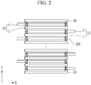
- FIG. 2 illustrates a cross-sectional view taken along a line II-II of FIG. 1
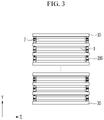
- FIG. 3 illustrates a cross-sectional view taken along a line III-III of FIG. 1 .
- an electrode assembly 100 is a stacked electrode assembly in which a negative electrode 10 and a positive electrode 20 are repeatedly stacked with a separator 30 interposed therebetween.
- the separator 30 is a polymer film through which lithium ions pass, and may be, for example, a polyolefin series.
- the negative electrode 10 includes an electrode region 1 formed by coating an active material on a current collector of a thin metal plate, and an uncoated region 3 where the thin metal plate is exposed by coating no active material thereon.
- a thin metal plate of the negative electrode may be a thin copper (Cu) plate.
- the positive 20 includes an electrode region 2 formed by coating an active material on a current collector of a thin metal plate, and an uncoated region 4 where the thin metal plate is exposed by coating no active material thereon.
- a thin metal plate of the positive electrode may be a thin aluminum (Al) plate.
- a plurality of respective uncoated regions 3 and 4 of the same polarity may be electrically connected to an outer terminal.
- the uncoated region 4 of the positive electrode 20 and the uncoated region 3 of the negative electrode 10 may protrude in opposite directions as illustrated in FIG. 1 , but the present invention is not limited thereto, and they may protrude in a same direction to be spaced apart from each other.
- the electrode assembly 100 is formed by repeatedly stacked the plurality of positive electrodes 20 and negative electrodes 10 with the separators 30 therebetween, and thus they may be fixed by using a fixing member 200 to maintain an aligned state after being stacked.
- the fixing member 200 has an elastic force and includes an adhesive layer made of a material having excellent adhesion to the separator 30, and the adhesive layer may include a polyolefin grafted with maleic anhydride having excellent adhesion to the separator 30 made of a polyolefin-based series.
- the polyolefin may be any one of polypropylene, polyethylene, and ethylene vinyl acetate (EVA).
- the fixing member 200 may be formed at a regular interval along an edge of the separator 30 to facilitate penetration of an electrolyte solution into the electrode assembly.
- the fixing member 200 may be formed to overlap or form a linear shape (see FIG. 7 ) in a direction Y crossing at least one sidewall of the electrode assembly 100, which is a substantially rectangular parallelepiped.
- the separator 30 may be larger than the negative electrode 10 and the positive electrode 20, and may protrude out of the negative electrode 10 and the positive electrode 20, while the fixing member 200 may be disposed at the edge of the separator 30, which protrudes.
- the fixing member 200 may be formed at a same position in the direction Y in which a plurality of overlapping separators 30 overlap, that is, across the sidewalls. Accordingly, it is fixed by contacting a first surface and a second surface of the separator 30 facing each other. In this case, the fixing member 200 is disposed within the boundary of the separator 30 and does not protrude out.
- the contact area between the separator 30 and the fixing member 200 increases to firmly hold the separator, so that when a shock is applied to the electrode assembly 100 or it moves, the alignment of the positive electrode, the negative electrode, and the separator of the electrode assembly 100 may be prevented from being distorted.
- the fixing member since the fixing member has elasticity, even when the alignment is distorted due to the impact on the electrode assembly, the fixing member can be restored to its original alignment state by the elasticity of the fixing member.
- FIG. 4 illustrates a view for describing a method of forming the electrode assembly of FIG. 2 and FIG. 3 .
- the fixing member 200 may be formed by repeating processes of disposing the positive electrode 20 on the separator 30, forming the fixing member 200 at the edge of the separator 30, disposing the separator 30 and the negative electrode 10, and forming the fixing member 200 at the edge of the separator 30.
- the process of forming the fixing member 200 includes a step of applying a solution adhesive to the edge and curing it.
- the fixing member 200 may be formed of a solution-type adhesive capable of thermosetting or UV curing and the fixing member 200 may be a material having excellent adhesion to the separator 30 but inferior adhesion to the metal sheets of the positive electrode and the negative electrode.
- the fixing member 200 may include a polyolefin grafted with maleic anhydride.
- the polyolefin may be any one of polypropylene, polyethylene, and ethylene vinyl acetate (EVA).
- the solution-type adhesive may be applied to the separator 30, and then move along the first surface of the separator 30. Therefore, after the solution-type adhesive is applied to the edge, viscosity and an amount of application of the solution-type adhesive are adjusted so as to not contact the end of the positive electrode or the negative electrode while moving along one surface of the separator 30.
- thermal curing or UV curing is rapidly performed after application to block the contact between the solution-type adhesive and the ends of the positive electrode and the negative electrode.
- the fixing member 200 is formed at a regular interval along the edge of the separator 30, and forms the fixing member 200 to overlap at a same position.
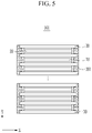
- FIG. 5 illustrates a schematic cross-sectional view of an electrode assembly according to another exemplary embodiment of the present invention, which is taken along the line III-III of FIG. 1 .
- an electrode assembly 101 includes the positive electrode 20 and the negative electrode 10 that are repeatedly stacked with the separator 30 interposed therebetween.
- the separator 30 is formed larger than the positive electrode 20 and the negative electrode 10, and a protruding edge thereof is fixed in contact with a fixing member 201.
- the fixing member 201 may be formed to contact the end of the separator 30 as well as the first surface of the separators 30 facing each other.
- the fixing member 201 of FIG. 2 and FIG. 3 is in contact with the first surface of the separators 30 facing each other, while the fixing member 201 of FIG. 5 is in contact not only with the first surface of the separators 30 facing each other, but also the end of the separators 30, and thus the area between the fixing member 201 and the separator 30 is wider.
- the separators may be more firmly fixed, and thus the alignment of the stacked electrode assembly may be more effectively prevented from being misaligned.
- FIG. 6 illustrates a view for describing a method of forming the electrode assembly of FIG. 5 .
- an electrode assembly in which the positive electrode 20, the separator 30, and the positive electrode 10 are stacked is prepared, and the solution-type adhesive is applied to the end of the separator 30 by using a nozzle-type applicator 300, and then is cured to form the fixing member 201.
- the fixing member 201 may be a solution-type adhesive capable of thermosetting or UV curing, and the fixing member 200 may be a material having excellent adhesion to the separator 30 but inferior adhesion to the metal sheets of the positive electrode and the negative electrode.
- the fixing member 201 may include a polyolefin grafted with maleic anhydride.
- the polyolefin may be any one of polypropylene, polyethylene, and ethylene vinyl acetate (EVA).
- the solution-type adhesive may be applied to the separator 30, and then move along the first surface of the separator 30. Therefore, after the solution-type adhesive is applied to the edge, a concentration and an amount of application of the solution-type adhesive is adjusted so as to not contact the end of the positive electrode or the negative electrode while moving along one surface of the separator 30.
- thermal curing or UV curing is rapidly performed after application to prevent the contact between the solution-type adhesive and the ends of the positive electrode and the negative electrode.
- the fixing member 201 since the fixing member 201 is applied by using the nozzle-type applicator 300, the fixing member 201 may be formed in a continuous linear shape in the direction Y across a sidewall of the electrode assembly 101, but the present invention is not limited thereto, and it may be formed discontinuously (not illustrated) at a regular interval along the direction Y crossing the sidewall or a longitudinal direction X of the sidewall.
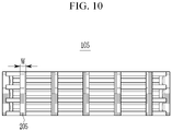
- FIG. 7 to FIG. 10 illustrate views for describing a fixing member according to another embodiment of the present invention.
- a fixing member 202 may be formed across the sidewall of an electrode assembly 102, 103, 104, 105 in various forms.
- the fixing member 202 may be formed perpendicularly with respect to upper and lower surfaces of the electrode assembly 102, or as illustrated in FIG. 8 and FIG. 9 , a fixing member 203 or 204 may be formed to be inclined with respect to an upper surface or a lower surface of an electrode assembly 103 or 104.
- a fixing member 205 may be formed to have a width W that is wider than that of the fixing members 202, 203, and 204 of FIG. 7 to FIG. 9 .
- an area corresponding to the sidewall is formed to be 95 % or less of a total sidewall area so that the fixing members 202, 203, 204, and 205 do not block penetration of the electrolyte solution.
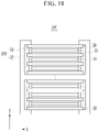
- FIG. 11 illustrates a schematic cross-sectional view of an electrode assembly according to another exemplary embodiment of the present invention, which is taken along the line III-III of FIG. 1 .
- an electrode assembly 106 includes the positive electrode and the negative electrode that are repeatedly stacked with the separator 30 interposed therebetween.
- the separator 30 is formed to be larger than the positive electrode and the negative electrode, and the fixing member 206 is attached to a protruding edge thereof.
- the fixing member 206 may include an insulating member 22 and an adhesive layer 24. As illustrated in FIG. 5 , the adhesive layer 24 may be formed to contact the end of the separator 30 as well as the first surface of the separators 30 facing each other.
- the insulating member 22 may be formed to surround upper and lower surfaces of the electrode assembly 106 together with the adhesive layer 24. Accordingly, upper and lower end portions of the insulating member 22 on which the adhesive layer 24 is not formed may have adhesiveness and may be attached to the upper and lower surfaces of the electrode assembly 106.
- the insulating member 22 having adhesiveness is formed together with the adhesive layer 24
- the insulating member 22 is attached to the upper and lower surfaces of the electrode assembly 106 to fix the fixing member 206 and the electrode, whereby an area contacted by the electrode assembly 106 may be increased to more firmly maintain the alignment of the electrode assembly 106.
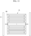
- the electrode assembly described in FIG. 11 may be formed by methods of FIG. 12 and FIG. 13 .
- FIG. 12 and FIG. 13 illustrate views for describing a method of forming a fixing member in an electrode assembly according to another exemplary embodiment of the present invention.
- the fixing member 207 may include an adhesive layer 24 and an insulating member 22.
- the fixing member 207 may have adhesiveness, and the adhesive layer 24 may be a hot melt adhesive that melts when a predetermined temperature is applied. Since the hot melt adhesive does not use an organic solvent, a risk due to the use of the organic solvent may be reduced.
- the adhesive layer 24 may include any one polymer selected from the group consisting of cellulose, polyvinylidene fluoride-cohexafluoropropylene, polyvinylidene fluoridecotrichloroethylene, polymethylmethacrylate, polybutylacrylate, polybutylacrylate acrylonitrile, polyvinylpyrrolidone, polyvinylacetate, ethylene vinyl co-vinyl acetate, polyethylene oxide, polyarylate, cellulose acetate, cellulose acetate butyrate, cellulose acetate propionate, cyanoethylpullulan, cyanoethylpolyvinylalcohol, cyanoethylcellulose, cyanoethylsucrose, pullulan, carboxyl methyl cellulose, or a maleic acid anhydride-polypropylene, or a mixture of two or more thereof, and preferably, may include polypropylene-maleic acid anhydride.
- a fixing member 207 is disposed so that the adhesive layer 22 is disposed on a sidewall of the electrode assembly 107 and is heated to melt the adhesive layer 24, and then the adhesive layer 24 is adhered to the separator by removing the heat and curing it.
- the adhesive layer 24 may be adhered between adjacent separators while being cured by UV.
- the adhesive layer 24 may move to an end of the positive electrode or the negative electrode during curing depending on viscosity, and thus the thickness, viscosity, melting temperature, time, etc. of the adhesive layer 24 are adjusted so that the adhesive layer 24 does not come into contact with the ends of the positive electrode and the negative electrode even when the adhesive layer 24 moves between the separators.
- the adhesive layer 24 may have viscosity of 500 cP or more.
- the adhesive layer 24 may be cured before contacting the ends of the positive and negative electrodes.
- the adhesive layer 24 may be formed using an adhesive having viscosity of 500 cP to prevent the adhesive from moving during curing with UV.
- the insulating member 22 having adhesiveness may be further attached onto an adhesive layer, which is the fixing member 202 of the electrode assembly 102 illustrated in FIG. 5 .
- the above electrode assembly may be assembled as a rechargeable battery by being inserted into a can-shaped case (not illustrated) together with an electrolyte solution, and then sealing it with a cap plate connectable to an external terminal.
Landscapes
- Chemical & Material Sciences (AREA)
- Chemical Kinetics & Catalysis (AREA)
- Electrochemistry (AREA)
- General Chemical & Material Sciences (AREA)
- Engineering & Computer Science (AREA)
- Manufacturing & Machinery (AREA)
- Secondary Cells (AREA)
- Cell Separators (AREA)
Claims (13)
- Eine Elektrodenanordnung, aufweisend:eine Vielzahl positiver Elektroden (10) und eine Vielzahl negativer Elektroden (20), die abwechselnd und wiederholt gestapelt sind, wobei jede der Vielzahl positiver Elektroden einen Elektrodenbereich (1) aufweist und jede der Vielzahl negativen Elektroden einen Elektrodenbereich (2) aufweist;eine Vielzahl von Separatoren (30), wobei jeder Separator zwischen jeder der Vielzahl positiver Elektroden und jeder der Vielzahl negativer Elektroden angeordnet ist, um vom Elektrodenbereich der positiven Elektrode und vom Elektrodenbereich der negativen Elektrode vorzustehen, und derart gestapelt ist, dass eine erste Oberfläche von Rändern davon einander zugewandt ist; undein Befestigungselement (200), das eine Klebeschicht (24), die an den Rändern jedes der Vielzahl einander zugewandter Separatoren angeklebt ist, aufweist,wobei die Klebeschicht (24) von Enden des Elektrodenbereichs (1, 2) jeder der Vielzahl positiver Elektroden oder jeder der Vielzahl negativer Elektroden beabstandet ist, undwobei das Befestigungselement ferner ein Isolierelement (22), das an einer Oberseite eines obersten Separators und einer Unterseite eines untersten Separators (30) angeklebt ist, aufweist.
- Die Elektrodenanordnung nach Anspruch 1, wobei
die Klebeschicht (24) ausgebildet ist, um Enden jedes der Separatoren zu umgeben. - Die Elektrodenanordnung nach Anspruch 1, wobei
die Klebeschicht (24) in einem regelmäßigen Abstand entlang der Ränder der Vielzahl von Separatoren (30) ausgebildet ist. - Die Elektrodenanordnung nach Anspruch 1, wobei
die Klebeschicht (24) miteinander in einer Richtung verbunden ist, in der sich die Separatoren überlappen, um eine lineare Form auszubilden. - Die Elektrodenanordnung nach Anspruch 4, wobei die Klebeschicht (24) bezüglich der Überlappungsrichtung geneigt ist.
- Die Elektrodenanordnung nach einem der vorhergehenden Ansprüche, wobeider Separator (30) aus einer Polyolefinreihe besteht unddas Befestigungselement (200) ein Polyolefin, das mit Maleinsäureanhydrid gepfropft ist, aufweist.
- Ein Verfahren zur Herstellung der Elektrodenanordnung nach einem der Ansprüche 1 bis 6, wobei das Verfahren die folgenden Schritte aufweist:Ausbilden einer Elektrodenanordnung durch wiederholtes Stapeln einer positiven Elektrode (10), eines Separators (30) und einer negativen Elektrode (20);Aufbringen eines Klebers vom Lösungstyp auf eine Seitenwand der Elektrodenanordnung; undAusbilden einer Klebeschicht (24) durch Aushärten des Klebers vom Lösungstyp,Befestigen eines Isolierelements (22) auf der Klebeschicht (24) nach dem Ausbilden der Klebeschicht (24),wobei der Kleber vom Lösungstyp in einer Richtung aufgebracht wird, in der Separatoren (30), die gestapelt sind, sich überlappen, undwobei das Isolierelement befestigt wird, um mit einer Ober- und Unterseite der Elektrodenanordnung in Kontakt zu treten.
- Das Herstellungsverfahren nach Anspruch 7, wobei
die Klebeschicht (24) eine Vielzahl von Klebeschichten aufweist und diese in einem regelmäßigen Abstand ausgebildet werden. - Das Herstellungsverfahren nach Anspruch 7 oder 8, wobei
die Klebeschicht ausgebildet wird, um eine Fläche von 95 % oder weniger bezüglich einer Fläche der Seitenwand aufzuweisen. - Das Herstellungsverfahren nach einem der Ansprüche 7 bis 9, wobeidie positive Elektrode (10) und die negative Elektrode (20) jeweils einen Elektrodenbereich (1, 3) aufweisen, undim Schritt des Aufbringens des Klebers vom Lösungstypder Kleber vom Lösungstyp aufgebracht wird, um von Enden des Elektrodenbereichs (1, 3) der positiven Elektrode und der negativen Elektrode beabstandet zu sein.
- Das Herstellungsverfahren nach einem der Ansprüche 7 bis 10, wobei im Schritt des Ausbildens der Klebeschicht (24)
das Aushärten Wärmehärten oder UV-Härten aufweist. - Ein Verfahren zur Herstellung der Elektrodenanordnung nach einem der Ansprüche 1 bis 6, wobei das Verfahren die folgenden Schritte aufweist:Ausbilden einer Elektrodenanordnung durch wiederholtes Stapeln einer positiven Elektrode (10), eines Separators (30) und einer negativen Elektrode (20);Anordnen eines Befestigungselements (200), das eine Klebeschicht (24) und ein Isolierelement (22) auf einer Seitenwand der Elektrodenanordnung aufweist; undSchmelzen und Aushärten der Klebeschicht (24),wobei die Klebeschicht (24) einen Heißschmelzkleber aufweist.
- Das Herstellungsverfahren nach Anspruch 12, wobeidas Befestigungselement (200) eine Vielzahl von Befestigungselementen aufweist und diese in einem regelmäßigen Abstand angeordnet werden, und/oderwobeidie positive Elektrode (10) und die negative Elektrode (20) jeweils einen Elektrodenbereich (1, 3) aufweisen, undim Schritt des Aushärtensdie Klebeschicht von Enden des Elektrodenbereichs (1, 3) der positiven Elektrode oder der negativen Elektrode beabstandet wird.
Applications Claiming Priority (1)
| Application Number | Priority Date | Filing Date | Title |
|---|---|---|---|
| KR1020180142977A KR102164003B1 (ko) | 2018-11-19 | 2018-11-19 | 전극 조립체 및 그의 제조 방법 |
Publications (2)
| Publication Number | Publication Date |
|---|---|
| EP3654409A1 EP3654409A1 (de) | 2020-05-20 |
| EP3654409B1 true EP3654409B1 (de) | 2022-10-26 |
Family
ID=68766463
Family Applications (1)
| Application Number | Title | Priority Date | Filing Date |
|---|---|---|---|
| EP19210077.4A Active EP3654409B1 (de) | 2018-11-19 | 2019-11-19 | Elektrodenanordnung und verfahren zur herstellung davon |
Country Status (6)
| Country | Link |
|---|---|
| US (3) | US11784378B2 (de) |
| EP (1) | EP3654409B1 (de) |
| KR (1) | KR102164003B1 (de) |
| CN (1) | CN111200156B (de) |
| HU (1) | HUE060766T2 (de) |
| PL (1) | PL3654409T3 (de) |
Families Citing this family (15)
| Publication number | Priority date | Publication date | Assignee | Title |
|---|---|---|---|---|
| KR20220045353A (ko) * | 2020-10-05 | 2022-04-12 | 현대자동차주식회사 | 배터리 모듈 |
| WO2022108080A1 (ko) | 2020-11-18 | 2022-05-27 | 주식회사 엘지에너지솔루션 | 이차 전지 및 이의 제조 방법 |
| WO2022250307A1 (ko) * | 2021-05-24 | 2022-12-01 | 주식회사 엘지에너지솔루션 | 단위 셀 및 이를 포함하는 전지 셀 |
| EP4199235B1 (de) | 2021-05-24 | 2025-08-20 | LG Energy Solution, Ltd. | Einheitszelle und batteriezelle damit |
| KR20230024796A (ko) | 2021-08-12 | 2023-02-21 | 주식회사 엘지에너지솔루션 | 전극 조립체 및 그 제조 방법 |
| CN113594618B (zh) * | 2021-08-16 | 2025-08-26 | 宁德新能源科技有限公司 | 电池组及用电设备 |
| WO2023048431A1 (ko) * | 2021-09-27 | 2023-03-30 | 주식회사 엘지에너지솔루션 | 전극 조립체 및 이를 포함하는 전지셀 |
| EP4300647A4 (de) * | 2021-10-07 | 2025-06-11 | LG Energy Solution, Ltd. | Elektrodenanordnung und batteriezelle damit |
| KR102558420B1 (ko) * | 2021-11-23 | 2023-07-24 | 삼성에스디아이 주식회사 | 이차전지 |
| JP7686930B2 (ja) * | 2021-12-06 | 2025-06-03 | エルジー エナジー ソリューション リミテッド | 電極アセンブリ、その製造方法およびこれを含む電池セル |
| KR102784243B1 (ko) * | 2022-01-20 | 2025-03-21 | 삼성에스디아이 주식회사 | 이차전지 |
| JP2024535619A (ja) * | 2022-05-10 | 2024-09-30 | エルジー エナジー ソリューション リミテッド | 電極組立体、その製造方法およびこれを含む電池セル |
| KR20250039773A (ko) * | 2023-09-14 | 2025-03-21 | 삼성에스디아이 주식회사 | 이차전지 |
| JP2025043088A (ja) * | 2023-09-15 | 2025-03-28 | トヨタ自動車株式会社 | 電極積層体、及び電池 |
| KR20250041449A (ko) * | 2023-09-18 | 2025-03-25 | 삼성에스디아이 주식회사 | 전극 조립체 및 이를 포함하는 이차 전지 |
Family Cites Families (30)
| Publication number | Priority date | Publication date | Assignee | Title |
|---|---|---|---|---|
| JP4564118B2 (ja) | 1999-10-26 | 2010-10-20 | パナソニック株式会社 | 電池及びその製造方法 |
| US6433091B1 (en) * | 2001-05-10 | 2002-08-13 | Henkel Loctite Corporation | Adhesive composition |
| US7177137B2 (en) | 2002-04-15 | 2007-02-13 | Avx Corporation | Plated terminations |
| CN1799112A (zh) | 2003-04-08 | 2006-07-05 | 阿维科斯公司 | 电镀端头 |
| US20050137549A1 (en) * | 2003-12-22 | 2005-06-23 | Kimberly-Clark Worldwide, Inc. | Use of swirl-like adhesive patterns in the formation of absorbent articles |
| KR100579376B1 (ko) | 2004-10-28 | 2006-05-12 | 삼성에스디아이 주식회사 | 이차 전지 |
| DE102005042916A1 (de) * | 2005-09-08 | 2007-03-22 | Degussa Ag | Stapel aus abwechselnd übereinander gestapelten und fixierten Separatoren und Elektroden für Li-Akkumulatoren |
| KR100853619B1 (ko) | 2006-01-04 | 2008-08-25 | 주식회사 엘지화학 | 분리막 상단이 밀봉되어 있는 전극조립체 및 이를 포함하는이차전지 |
| US20100019365A1 (en) * | 2006-09-12 | 2010-01-28 | Nitto Denko Corporation | Dicing/die bonding film |
| EP2259353B1 (de) | 2008-04-21 | 2012-06-27 | Murata Manufacturing Co. Ltd. | Mehrschichtiger piezoelektrischer aktuator |
| US20110244319A1 (en) * | 2009-03-31 | 2011-10-06 | Mitsubishi Heavy Industries, Ltd. | Secondary battery and battery system |
| JP5982131B2 (ja) * | 2011-02-28 | 2016-08-31 | 日東電工株式会社 | 電池用粘着テープ、及び該粘着テープを使用した電池 |
| JP2012248465A (ja) | 2011-05-30 | 2012-12-13 | Sharp Corp | 二次電池およびその製造方法 |
| KR101905077B1 (ko) | 2012-01-19 | 2018-10-05 | 삼성에스디아이 주식회사 | 배터리 셀용 보강물 및 배터리 셀 |
| WO2014014118A1 (ja) * | 2012-07-18 | 2014-01-23 | 住友化学株式会社 | 接着層、層及び組成物 |
| KR101578265B1 (ko) * | 2013-02-26 | 2015-12-16 | 주식회사 엘지화학 | 안정성이 향상된 이차전지용 바이셀 및 그 제조방법 |
| KR101620173B1 (ko) | 2013-07-10 | 2016-05-13 | 주식회사 엘지화학 | 적층 형태 안정성이 우수한 단차를 갖는 전극 조립체 및 그 제조방법 |
| KR101624386B1 (ko) * | 2013-09-30 | 2016-05-25 | 주식회사 엘지화학 | 테이프를 이용한 전극조립체의 고정방법 |
| KR101598666B1 (ko) | 2013-09-30 | 2016-03-02 | 주식회사 엘지화학 | 테이프를 이용한 전극조립체의 고정방법 |
| KR101820442B1 (ko) | 2013-10-31 | 2018-01-19 | 주식회사 엘지화학 | 전지셀의 전극조립체 테이핑 장치 및 상기 테이핑 장치를 이용하여 제조된 전지셀 |
| KR102153044B1 (ko) * | 2013-11-11 | 2020-09-07 | 삼성전자주식회사 | 가요성 이차 전지 |
| KR101840859B1 (ko) | 2013-11-18 | 2018-03-22 | 주식회사 엘지화학 | 전극조립체 고정용 접착부재의 부가 장치 |
| KR102221807B1 (ko) | 2014-08-11 | 2021-03-02 | 삼성에스디아이 주식회사 | 이차 전지 |
| US10964934B2 (en) * | 2014-08-25 | 2021-03-30 | Nissan Motor Co., Ltd. | Laminate type battery and method for producing the same |
| US9768421B2 (en) * | 2014-10-10 | 2017-09-19 | Samsung Electronics Co., Ltd. | Flexible electrode assembly and electrochemical device having the electrode assembly |
| KR102454949B1 (ko) | 2014-10-10 | 2022-10-17 | 삼성전자주식회사 | 유연한 전극 조립체 및 이를 포함하는 전기화학 소자 |
| KR101628892B1 (ko) * | 2014-10-21 | 2016-06-09 | 주식회사 루트제이드 | 스텝 셀 구조를 가지는 이차전지 |
| EP3139434B1 (de) | 2015-09-04 | 2018-02-28 | Renata AG | Knopfzelle und verfahren zur herstellung solch einer knopfzelle |
| EP3211687B1 (de) * | 2016-02-24 | 2025-04-02 | Nitto Denko Corporation | Isolierband |
| KR102152143B1 (ko) * | 2016-11-24 | 2020-09-04 | 주식회사 엘지화학 | 전극판의 경계 부위에 절연 보강부가 형성된 분리막을 포함하는 전극조립체 |
-
2018
- 2018-11-19 KR KR1020180142977A patent/KR102164003B1/ko active Active
-
2019
- 2019-11-13 US US16/682,229 patent/US11784378B2/en active Active
- 2019-11-18 CN CN201911125383.4A patent/CN111200156B/zh active Active
- 2019-11-19 PL PL19210077.4T patent/PL3654409T3/pl unknown
- 2019-11-19 HU HUE19210077A patent/HUE060766T2/hu unknown
- 2019-11-19 EP EP19210077.4A patent/EP3654409B1/de active Active
-
2023
- 2023-06-28 US US18/343,274 patent/US12261323B2/en active Active
- 2023-07-24 US US18/357,696 patent/US12224453B2/en active Active
Also Published As
| Publication number | Publication date |
|---|---|
| HUE060766T2 (hu) | 2023-04-28 |
| KR20200058222A (ko) | 2020-05-27 |
| US20200161617A1 (en) | 2020-05-21 |
| CN111200156B (zh) | 2023-12-22 |
| US12261323B2 (en) | 2025-03-25 |
| US11784378B2 (en) | 2023-10-10 |
| US20230335864A1 (en) | 2023-10-19 |
| PL3654409T3 (pl) | 2023-01-09 |
| US20230369720A1 (en) | 2023-11-16 |
| CN111200156A (zh) | 2020-05-26 |
| EP3654409A1 (de) | 2020-05-20 |
| KR102164003B1 (ko) | 2020-10-12 |
| US12224453B2 (en) | 2025-02-11 |
Similar Documents
| Publication | Publication Date | Title |
|---|---|---|
| EP3654409B1 (de) | Elektrodenanordnung und verfahren zur herstellung davon | |
| JP6788107B2 (ja) | 電池セルのための電極ユニットの製造方法、及び、電極ユニット | |
| US10923758B2 (en) | Electrode assembly having step, secondary battery, battery pack and device including electrode assembly, and method of manufacturing electrode assembly | |
| CN110071322B (zh) | 二次电池及其制造方法 | |
| EP2985812B1 (de) | Sekundäre batterie | |
| KR102085342B1 (ko) | 이차전지용 전극리드, 이를 포함하는 파우치형 이차전지 및 배터리 모듈 | |
| US20110195298A1 (en) | Stacked secondary battery | |
| TWI893180B (zh) | 包括避免開路層之電極組合、包含其的二次電池以及其製造方法 | |
| KR102207132B1 (ko) | 실링된 분리막을 포함하는 전지셀용 전극조립체 | |
| US20230299433A1 (en) | Method for Welding Electrode Assembly | |
| KR20180057847A (ko) | 전극조립체 제조 장치 및 그 전극조립체 제조 장치에 의한 전극조립체 제조 방법 | |
| KR101425257B1 (ko) | 전극조립체 및 이를 이용한 이차 전지 | |
| JP2001307712A (ja) | 密閉型電池 | |
| KR101790230B1 (ko) | 절연 코팅층을 가진 전극단자를 포함하는 전지셀 | |
| US12224392B2 (en) | Electrode assembly and method of manufacturing the same | |
| KR101755073B1 (ko) | 이차전지 및 이의 제조방법 | |
| US20230163416A1 (en) | Secondary battery | |
| KR20230114119A (ko) | 전극 조립체 제조방법 | |
| KR20220100333A (ko) | 절연성 코팅층이 형성된 분리막을 포함하는 이차전지용 유닛셀, 및 이의 제조방법 | |
| US20250316798A1 (en) | Secondary battery | |
| US20250170816A1 (en) | Method for disassembling electrode body | |
| CN118285005A (zh) | 具有厚度补充单元的堆叠折叠式电极组件及其制造方法和包括该堆叠折叠式电极组件的二次电池 | |
| CN121620825A (zh) | 二次电池按压设备和使用二次电池按压设备的二次电池按压方法 |
Legal Events
| Date | Code | Title | Description |
|---|---|---|---|
| PUAI | Public reference made under article 153(3) epc to a published international application that has entered the european phase |
Free format text: ORIGINAL CODE: 0009012 |
|
| STAA | Information on the status of an ep patent application or granted ep patent |
Free format text: STATUS: REQUEST FOR EXAMINATION WAS MADE |
|
| 17P | Request for examination filed |
Effective date: 20191119 |
|
| AK | Designated contracting states |
Kind code of ref document: A1 Designated state(s): AL AT BE BG CH CY CZ DE DK EE ES FI FR GB GR HR HU IE IS IT LI LT LU LV MC MK MT NL NO PL PT RO RS SE SI SK SM TR |
|
| AX | Request for extension of the european patent |
Extension state: BA ME |
|
| RIC1 | Information provided on ipc code assigned before grant |
Ipc: H01M 50/46 20210101ALI20210927BHEP Ipc: H01M 50/183 20210101ALI20210927BHEP Ipc: H01M 50/409 20210101ALI20210927BHEP Ipc: H01M 10/0585 20100101ALI20210927BHEP Ipc: H01M 10/052 20100101ALI20210927BHEP Ipc: H01M 10/04 20060101ALI20210927BHEP Ipc: H01M 4/04 20060101AFI20210927BHEP |
|
| GRAP | Despatch of communication of intention to grant a patent |
Free format text: ORIGINAL CODE: EPIDOSNIGR1 |
|
| STAA | Information on the status of an ep patent application or granted ep patent |
Free format text: STATUS: GRANT OF PATENT IS INTENDED |
|
| INTG | Intention to grant announced |
Effective date: 20211116 |
|
| GRAJ | Information related to disapproval of communication of intention to grant by the applicant or resumption of examination proceedings by the epo deleted |
Free format text: ORIGINAL CODE: EPIDOSDIGR1 |
|
| STAA | Information on the status of an ep patent application or granted ep patent |
Free format text: STATUS: REQUEST FOR EXAMINATION WAS MADE |
|
| REG | Reference to a national code |
Ref country code: DE Ref legal event code: R079 Ref document number: 602019021041 Country of ref document: DE Free format text: PREVIOUS MAIN CLASS: H01M0002160000 Ipc: H01M0004040000 |
|
| INTC | Intention to grant announced (deleted) | ||
| RIC1 | Information provided on ipc code assigned before grant |
Ipc: H01M 50/417 20210101ALI20220322BHEP Ipc: H01M 50/46 20210101ALI20220322BHEP Ipc: H01M 50/183 20210101ALI20220322BHEP Ipc: H01M 50/409 20210101ALI20220322BHEP Ipc: H01M 10/0585 20100101ALI20220322BHEP Ipc: H01M 10/052 20100101ALI20220322BHEP Ipc: H01M 10/04 20060101ALI20220322BHEP Ipc: H01M 4/04 20060101AFI20220322BHEP |
|
| GRAP | Despatch of communication of intention to grant a patent |
Free format text: ORIGINAL CODE: EPIDOSNIGR1 |
|
| STAA | Information on the status of an ep patent application or granted ep patent |
Free format text: STATUS: GRANT OF PATENT IS INTENDED |
|
| INTG | Intention to grant announced |
Effective date: 20220520 |
|
| GRAS | Grant fee paid |
Free format text: ORIGINAL CODE: EPIDOSNIGR3 |
|
| GRAA | (expected) grant |
Free format text: ORIGINAL CODE: 0009210 |
|
| STAA | Information on the status of an ep patent application or granted ep patent |
Free format text: STATUS: THE PATENT HAS BEEN GRANTED |
|
| AK | Designated contracting states |
Kind code of ref document: B1 Designated state(s): AL AT BE BG CH CY CZ DE DK EE ES FI FR GB GR HR HU IE IS IT LI LT LU LV MC MK MT NL NO PL PT RO RS SE SI SK SM TR |
|
| REG | Reference to a national code |
Ref country code: GB Ref legal event code: FG4D |
|
| REG | Reference to a national code |
Ref country code: CH Ref legal event code: EP |
|
| REG | Reference to a national code |
Ref country code: AT Ref legal event code: REF Ref document number: 1527706 Country of ref document: AT Kind code of ref document: T Effective date: 20221115 |
|
| REG | Reference to a national code |
Ref country code: DE Ref legal event code: R096 Ref document number: 602019021041 Country of ref document: DE |
|
| REG | Reference to a national code |
Ref country code: IE Ref legal event code: FG4D |
|
| REG | Reference to a national code |
Ref country code: SE Ref legal event code: TRGR |
|
| REG | Reference to a national code |
Ref country code: LT Ref legal event code: MG9D |
|
| REG | Reference to a national code |
Ref country code: NL Ref legal event code: MP Effective date: 20221026 |
|
| REG | Reference to a national code |
Ref country code: AT Ref legal event code: MK05 Ref document number: 1527706 Country of ref document: AT Kind code of ref document: T Effective date: 20221026 |
|
| PG25 | Lapsed in a contracting state [announced via postgrant information from national office to epo] |
Ref country code: NL Free format text: LAPSE BECAUSE OF FAILURE TO SUBMIT A TRANSLATION OF THE DESCRIPTION OR TO PAY THE FEE WITHIN THE PRESCRIBED TIME-LIMIT Effective date: 20221026 |
|
| PG25 | Lapsed in a contracting state [announced via postgrant information from national office to epo] |
Ref country code: PT Free format text: LAPSE BECAUSE OF FAILURE TO SUBMIT A TRANSLATION OF THE DESCRIPTION OR TO PAY THE FEE WITHIN THE PRESCRIBED TIME-LIMIT Effective date: 20230227 Ref country code: NO Free format text: LAPSE BECAUSE OF FAILURE TO SUBMIT A TRANSLATION OF THE DESCRIPTION OR TO PAY THE FEE WITHIN THE PRESCRIBED TIME-LIMIT Effective date: 20230126 Ref country code: LT Free format text: LAPSE BECAUSE OF FAILURE TO SUBMIT A TRANSLATION OF THE DESCRIPTION OR TO PAY THE FEE WITHIN THE PRESCRIBED TIME-LIMIT Effective date: 20221026 Ref country code: FI Free format text: LAPSE BECAUSE OF FAILURE TO SUBMIT A TRANSLATION OF THE DESCRIPTION OR TO PAY THE FEE WITHIN THE PRESCRIBED TIME-LIMIT Effective date: 20221026 Ref country code: ES Free format text: LAPSE BECAUSE OF FAILURE TO SUBMIT A TRANSLATION OF THE DESCRIPTION OR TO PAY THE FEE WITHIN THE PRESCRIBED TIME-LIMIT Effective date: 20221026 Ref country code: AT Free format text: LAPSE BECAUSE OF FAILURE TO SUBMIT A TRANSLATION OF THE DESCRIPTION OR TO PAY THE FEE WITHIN THE PRESCRIBED TIME-LIMIT Effective date: 20221026 |
|
| REG | Reference to a national code |
Ref country code: HU Ref legal event code: AG4A Ref document number: E060766 Country of ref document: HU |
|
| PG25 | Lapsed in a contracting state [announced via postgrant information from national office to epo] |
Ref country code: RS Free format text: LAPSE BECAUSE OF FAILURE TO SUBMIT A TRANSLATION OF THE DESCRIPTION OR TO PAY THE FEE WITHIN THE PRESCRIBED TIME-LIMIT Effective date: 20221026 Ref country code: LV Free format text: LAPSE BECAUSE OF FAILURE TO SUBMIT A TRANSLATION OF THE DESCRIPTION OR TO PAY THE FEE WITHIN THE PRESCRIBED TIME-LIMIT Effective date: 20221026 Ref country code: IS Free format text: LAPSE BECAUSE OF FAILURE TO SUBMIT A TRANSLATION OF THE DESCRIPTION OR TO PAY THE FEE WITHIN THE PRESCRIBED TIME-LIMIT Effective date: 20230226 Ref country code: HR Free format text: LAPSE BECAUSE OF FAILURE TO SUBMIT A TRANSLATION OF THE DESCRIPTION OR TO PAY THE FEE WITHIN THE PRESCRIBED TIME-LIMIT Effective date: 20221026 Ref country code: GR Free format text: LAPSE BECAUSE OF FAILURE TO SUBMIT A TRANSLATION OF THE DESCRIPTION OR TO PAY THE FEE WITHIN THE PRESCRIBED TIME-LIMIT Effective date: 20230127 |
|
| REG | Reference to a national code |
Ref country code: CH Ref legal event code: PL |
|
| P01 | Opt-out of the competence of the unified patent court (upc) registered |
Effective date: 20230528 |
|
| REG | Reference to a national code |
Ref country code: DE Ref legal event code: R097 Ref document number: 602019021041 Country of ref document: DE Ref country code: BE Ref legal event code: MM Effective date: 20221130 |
|
| PG25 | Lapsed in a contracting state [announced via postgrant information from national office to epo] |
Ref country code: SM Free format text: LAPSE BECAUSE OF FAILURE TO SUBMIT A TRANSLATION OF THE DESCRIPTION OR TO PAY THE FEE WITHIN THE PRESCRIBED TIME-LIMIT Effective date: 20221026 Ref country code: RO Free format text: LAPSE BECAUSE OF FAILURE TO SUBMIT A TRANSLATION OF THE DESCRIPTION OR TO PAY THE FEE WITHIN THE PRESCRIBED TIME-LIMIT Effective date: 20221026 Ref country code: MC Free format text: LAPSE BECAUSE OF FAILURE TO SUBMIT A TRANSLATION OF THE DESCRIPTION OR TO PAY THE FEE WITHIN THE PRESCRIBED TIME-LIMIT Effective date: 20221026 Ref country code: LI Free format text: LAPSE BECAUSE OF NON-PAYMENT OF DUE FEES Effective date: 20221130 Ref country code: EE Free format text: LAPSE BECAUSE OF FAILURE TO SUBMIT A TRANSLATION OF THE DESCRIPTION OR TO PAY THE FEE WITHIN THE PRESCRIBED TIME-LIMIT Effective date: 20221026 Ref country code: DK Free format text: LAPSE BECAUSE OF FAILURE TO SUBMIT A TRANSLATION OF THE DESCRIPTION OR TO PAY THE FEE WITHIN THE PRESCRIBED TIME-LIMIT Effective date: 20221026 Ref country code: CZ Free format text: LAPSE BECAUSE OF FAILURE TO SUBMIT A TRANSLATION OF THE DESCRIPTION OR TO PAY THE FEE WITHIN THE PRESCRIBED TIME-LIMIT Effective date: 20221026 Ref country code: CH Free format text: LAPSE BECAUSE OF NON-PAYMENT OF DUE FEES Effective date: 20221130 |
|
| PG25 | Lapsed in a contracting state [announced via postgrant information from national office to epo] |
Ref country code: SK Free format text: LAPSE BECAUSE OF FAILURE TO SUBMIT A TRANSLATION OF THE DESCRIPTION OR TO PAY THE FEE WITHIN THE PRESCRIBED TIME-LIMIT Effective date: 20221026 Ref country code: LU Free format text: LAPSE BECAUSE OF NON-PAYMENT OF DUE FEES Effective date: 20221119 Ref country code: AL Free format text: LAPSE BECAUSE OF FAILURE TO SUBMIT A TRANSLATION OF THE DESCRIPTION OR TO PAY THE FEE WITHIN THE PRESCRIBED TIME-LIMIT Effective date: 20221026 |
|
| PLBE | No opposition filed within time limit |
Free format text: ORIGINAL CODE: 0009261 |
|
| STAA | Information on the status of an ep patent application or granted ep patent |
Free format text: STATUS: NO OPPOSITION FILED WITHIN TIME LIMIT |
|
| 26N | No opposition filed |
Effective date: 20230727 |
|
| PG25 | Lapsed in a contracting state [announced via postgrant information from national office to epo] |
Ref country code: IE Free format text: LAPSE BECAUSE OF NON-PAYMENT OF DUE FEES Effective date: 20221119 |
|
| PG25 | Lapsed in a contracting state [announced via postgrant information from national office to epo] |
Ref country code: SI Free format text: LAPSE BECAUSE OF FAILURE TO SUBMIT A TRANSLATION OF THE DESCRIPTION OR TO PAY THE FEE WITHIN THE PRESCRIBED TIME-LIMIT Effective date: 20221026 Ref country code: BE Free format text: LAPSE BECAUSE OF NON-PAYMENT OF DUE FEES Effective date: 20221130 |
|
| PG25 | Lapsed in a contracting state [announced via postgrant information from national office to epo] |
Ref country code: CY Free format text: LAPSE BECAUSE OF FAILURE TO SUBMIT A TRANSLATION OF THE DESCRIPTION OR TO PAY THE FEE WITHIN THE PRESCRIBED TIME-LIMIT Effective date: 20221026 |
|
| PG25 | Lapsed in a contracting state [announced via postgrant information from national office to epo] |
Ref country code: MK Free format text: LAPSE BECAUSE OF FAILURE TO SUBMIT A TRANSLATION OF THE DESCRIPTION OR TO PAY THE FEE WITHIN THE PRESCRIBED TIME-LIMIT Effective date: 20221026 Ref country code: IT Free format text: LAPSE BECAUSE OF FAILURE TO SUBMIT A TRANSLATION OF THE DESCRIPTION OR TO PAY THE FEE WITHIN THE PRESCRIBED TIME-LIMIT Effective date: 20221026 |
|
| PG25 | Lapsed in a contracting state [announced via postgrant information from national office to epo] |
Ref country code: TR Free format text: LAPSE BECAUSE OF FAILURE TO SUBMIT A TRANSLATION OF THE DESCRIPTION OR TO PAY THE FEE WITHIN THE PRESCRIBED TIME-LIMIT Effective date: 20221026 |
|
| PG25 | Lapsed in a contracting state [announced via postgrant information from national office to epo] |
Ref country code: BG Free format text: LAPSE BECAUSE OF FAILURE TO SUBMIT A TRANSLATION OF THE DESCRIPTION OR TO PAY THE FEE WITHIN THE PRESCRIBED TIME-LIMIT Effective date: 20221026 |
|
| PG25 | Lapsed in a contracting state [announced via postgrant information from national office to epo] |
Ref country code: MT Free format text: LAPSE BECAUSE OF FAILURE TO SUBMIT A TRANSLATION OF THE DESCRIPTION OR TO PAY THE FEE WITHIN THE PRESCRIBED TIME-LIMIT Effective date: 20221026 |
|
| PGFP | Annual fee paid to national office [announced via postgrant information from national office to epo] |
Ref country code: HU Payment date: 20251127 Year of fee payment: 7 |
|
| PGFP | Annual fee paid to national office [announced via postgrant information from national office to epo] |
Ref country code: DE Payment date: 20251104 Year of fee payment: 7 |
|
| PGFP | Annual fee paid to national office [announced via postgrant information from national office to epo] |
Ref country code: GB Payment date: 20251030 Year of fee payment: 7 |
|
| PGFP | Annual fee paid to national office [announced via postgrant information from national office to epo] |
Ref country code: FR Payment date: 20251117 Year of fee payment: 7 |
|
| PGFP | Annual fee paid to national office [announced via postgrant information from national office to epo] |
Ref country code: SE Payment date: 20251112 Year of fee payment: 7 |
|
| PGFP | Annual fee paid to national office [announced via postgrant information from national office to epo] |
Ref country code: PL Payment date: 20251103 Year of fee payment: 7 |