EP3653989A1 - Imaging device and monitoring device - Google Patents
Imaging device and monitoring device Download PDFInfo
- Publication number
- EP3653989A1 EP3653989A1 EP18831506.3A EP18831506A EP3653989A1 EP 3653989 A1 EP3653989 A1 EP 3653989A1 EP 18831506 A EP18831506 A EP 18831506A EP 3653989 A1 EP3653989 A1 EP 3653989A1
- Authority
- EP
- European Patent Office
- Prior art keywords
- light
- distance
- sensor unit
- distance measuring
- specular reflector
- Prior art date
- Legal status (The legal status is an assumption and is not a legal conclusion. Google has not performed a legal analysis and makes no representation as to the accuracy of the status listed.)
- Granted
Links
Images







Classifications
-
- G—PHYSICS
- G01—MEASURING; TESTING
- G01S—RADIO DIRECTION-FINDING; RADIO NAVIGATION; DETERMINING DISTANCE OR VELOCITY BY USE OF RADIO WAVES; LOCATING OR PRESENCE-DETECTING BY USE OF THE REFLECTION OR RERADIATION OF RADIO WAVES; ANALOGOUS ARRANGEMENTS USING OTHER WAVES
- G01S7/00—Details of systems according to groups G01S13/00, G01S15/00, G01S17/00
- G01S7/48—Details of systems according to groups G01S13/00, G01S15/00, G01S17/00 of systems according to group G01S17/00
- G01S7/497—Means for monitoring or calibrating
-
- A—HUMAN NECESSITIES
- A61—MEDICAL OR VETERINARY SCIENCE; HYGIENE
- A61C—DENTISTRY; APPARATUS OR METHODS FOR ORAL OR DENTAL HYGIENE
- A61C9/00—Impression cups, i.e. impression trays; Impression methods
- A61C9/004—Means or methods for taking digitized impressions
- A61C9/0046—Data acquisition means or methods
- A61C9/0053—Optical means or methods, e.g. scanning the teeth by a laser or light beam
-
- A—HUMAN NECESSITIES
- A61—MEDICAL OR VETERINARY SCIENCE; HYGIENE
- A61C—DENTISTRY; APPARATUS OR METHODS FOR ORAL OR DENTAL HYGIENE
- A61C9/00—Impression cups, i.e. impression trays; Impression methods
- A61C9/004—Means or methods for taking digitized impressions
- A61C9/0046—Data acquisition means or methods
- A61C9/0053—Optical means or methods, e.g. scanning the teeth by a laser or light beam
- A61C9/006—Optical means or methods, e.g. scanning the teeth by a laser or light beam projecting one or more stripes or patterns on the teeth
-
- A—HUMAN NECESSITIES
- A61—MEDICAL OR VETERINARY SCIENCE; HYGIENE
- A61C—DENTISTRY; APPARATUS OR METHODS FOR ORAL OR DENTAL HYGIENE
- A61C9/00—Impression cups, i.e. impression trays; Impression methods
- A61C9/004—Means or methods for taking digitized impressions
- A61C9/0046—Data acquisition means or methods
- A61C9/0053—Optical means or methods, e.g. scanning the teeth by a laser or light beam
- A61C9/0073—Interferometric means or methods, e.g. creation of a hologram
-
- G—PHYSICS
- G01—MEASURING; TESTING
- G01B—MEASURING LENGTH, THICKNESS OR SIMILAR LINEAR DIMENSIONS; MEASURING ANGLES; MEASURING AREAS; MEASURING IRREGULARITIES OF SURFACES OR CONTOURS
- G01B11/00—Measuring arrangements characterised by the use of optical techniques
- G01B11/24—Measuring arrangements characterised by the use of optical techniques for measuring contours or curvatures
-
- G—PHYSICS
- G01—MEASURING; TESTING
- G01N—INVESTIGATING OR ANALYSING MATERIALS BY DETERMINING THEIR CHEMICAL OR PHYSICAL PROPERTIES
- G01N21/00—Investigating or analysing materials by the use of optical means, i.e. using sub-millimetre waves, infrared, visible or ultraviolet light
- G01N21/17—Systems in which incident light is modified in accordance with the properties of the material investigated
- G01N21/25—Colour; Spectral properties, i.e. comparison of effect of material on the light at two or more different wavelengths or wavelength bands
- G01N21/27—Colour; Spectral properties, i.e. comparison of effect of material on the light at two or more different wavelengths or wavelength bands using photo-electric detection ; circuits for computing concentration
-
- G—PHYSICS
- G01—MEASURING; TESTING
- G01N—INVESTIGATING OR ANALYSING MATERIALS BY DETERMINING THEIR CHEMICAL OR PHYSICAL PROPERTIES
- G01N21/00—Investigating or analysing materials by the use of optical means, i.e. using sub-millimetre waves, infrared, visible or ultraviolet light
- G01N21/17—Systems in which incident light is modified in accordance with the properties of the material investigated
- G01N21/55—Specular reflectivity
-
- G—PHYSICS
- G01—MEASURING; TESTING
- G01S—RADIO DIRECTION-FINDING; RADIO NAVIGATION; DETERMINING DISTANCE OR VELOCITY BY USE OF RADIO WAVES; LOCATING OR PRESENCE-DETECTING BY USE OF THE REFLECTION OR RERADIATION OF RADIO WAVES; ANALOGOUS ARRANGEMENTS USING OTHER WAVES
- G01S17/00—Systems using the reflection or reradiation of electromagnetic waves other than radio waves, e.g. lidar systems
- G01S17/02—Systems using the reflection of electromagnetic waves other than radio waves
- G01S17/06—Systems determining position data of a target
- G01S17/08—Systems determining position data of a target for measuring distance only
-
- G—PHYSICS
- G01—MEASURING; TESTING
- G01S—RADIO DIRECTION-FINDING; RADIO NAVIGATION; DETERMINING DISTANCE OR VELOCITY BY USE OF RADIO WAVES; LOCATING OR PRESENCE-DETECTING BY USE OF THE REFLECTION OR RERADIATION OF RADIO WAVES; ANALOGOUS ARRANGEMENTS USING OTHER WAVES
- G01S17/00—Systems using the reflection or reradiation of electromagnetic waves other than radio waves, e.g. lidar systems
- G01S17/02—Systems using the reflection of electromagnetic waves other than radio waves
- G01S17/06—Systems determining position data of a target
- G01S17/08—Systems determining position data of a target for measuring distance only
- G01S17/32—Systems determining position data of a target for measuring distance only using transmission of continuous waves, whether amplitude-, frequency-, or phase-modulated, or unmodulated
- G01S17/36—Systems determining position data of a target for measuring distance only using transmission of continuous waves, whether amplitude-, frequency-, or phase-modulated, or unmodulated with phase comparison between the received signal and the contemporaneously transmitted signal
-
- G—PHYSICS
- G01—MEASURING; TESTING
- G01S—RADIO DIRECTION-FINDING; RADIO NAVIGATION; DETERMINING DISTANCE OR VELOCITY BY USE OF RADIO WAVES; LOCATING OR PRESENCE-DETECTING BY USE OF THE REFLECTION OR RERADIATION OF RADIO WAVES; ANALOGOUS ARRANGEMENTS USING OTHER WAVES
- G01S17/00—Systems using the reflection or reradiation of electromagnetic waves other than radio waves, e.g. lidar systems
- G01S17/88—Lidar systems specially adapted for specific applications
- G01S17/89—Lidar systems specially adapted for specific applications for mapping or imaging
-
- G—PHYSICS
- G06—COMPUTING OR CALCULATING; COUNTING
- G06F—ELECTRIC DIGITAL DATA PROCESSING
- G06F18/00—Pattern recognition
- G06F18/20—Analysing
- G06F18/22—Matching criteria, e.g. proximity measures
-
- G—PHYSICS
- G06—COMPUTING OR CALCULATING; COUNTING
- G06T—IMAGE DATA PROCESSING OR GENERATION, IN GENERAL
- G06T7/00—Image analysis
- G06T7/0002—Inspection of images, e.g. flaw detection
-
- H—ELECTRICITY
- H04—ELECTRIC COMMUNICATION TECHNIQUE
- H04N—PICTORIAL COMMUNICATION, e.g. TELEVISION
- H04N23/00—Cameras or camera modules comprising electronic image sensors; Control thereof
- H04N23/56—Cameras or camera modules comprising electronic image sensors; Control thereof provided with illuminating means
-
- G—PHYSICS
- G01—MEASURING; TESTING
- G01B—MEASURING LENGTH, THICKNESS OR SIMILAR LINEAR DIMENSIONS; MEASURING ANGLES; MEASURING AREAS; MEASURING IRREGULARITIES OF SURFACES OR CONTOURS
- G01B21/00—Measuring arrangements or details thereof, where the measuring technique is not covered by the other groups of this subclass, unspecified or not relevant
- G01B21/02—Measuring arrangements or details thereof, where the measuring technique is not covered by the other groups of this subclass, unspecified or not relevant for measuring length, width, or thickness
- G01B21/04—Measuring arrangements or details thereof, where the measuring technique is not covered by the other groups of this subclass, unspecified or not relevant for measuring length, width, or thickness by measuring coordinates of points
- G01B21/045—Correction of measurements
-
- G—PHYSICS
- G06—COMPUTING OR CALCULATING; COUNTING
- G06T—IMAGE DATA PROCESSING OR GENERATION, IN GENERAL
- G06T2207/00—Indexing scheme for image analysis or image enhancement
- G06T2207/10—Image acquisition modality
- G06T2207/10024—Color image
-
- G—PHYSICS
- G06—COMPUTING OR CALCULATING; COUNTING
- G06T—IMAGE DATA PROCESSING OR GENERATION, IN GENERAL
- G06T2207/00—Indexing scheme for image analysis or image enhancement
- G06T2207/30—Subject of image; Context of image processing
- G06T2207/30204—Marker
Definitions
- the present disclosure relates to an imaging device and a monitoring device.
- Distance measuring cameras that emit infrared light or the like to an object and receive the infrared light reflected by the object to measure a distance to the object or a surface shape of the object are known.
- An example of such a distance measuring camera includes a technology disclosed in Patent Document 1 below.
- the light in the first path is light that reaches the object from the distance measuring camera, is directly reflected by the object, and returns to the distance measuring camera.
- the light in the second path reaches the specular reflector from the distance measuring camera, is reflected by the specular reflector, reaches the object, and further returns from the object to the distance measuring camera via the specular reflector in the same path.
- the light from these two different paths may interfere on the same point (surface) of the object (this phenomenon is called interference due to multipath) depending on the shape of the object.
- the distance measuring camera may not be able to correctly measure the distance and shape of the object due to reception of interference light.
- the technology disclosed in Patent Document 2 does not measure the object in consideration of the interference due to multipath as described above, it is difficult to accurately measure the distance and shape of the object.
- the present disclosure proposes, in view of the foregoing, new and improved imaging device and monitoring device capable of accurately measuring a distance and a shape of a region of an object that is difficult to directly measure by one distance measuring camera.
- an imaging device including: a sensor unit configured to irradiate an object with light and detect the light reflected by the object; a distance calculation unit configured to calculate a distance to the object on the basis of sensing data of the sensor unit; a specular reflector located on an opposite side of the sensor unit across the object; and a correction unit configured to correct an error included in the calculated distance, the error being caused by an interference between the light following a first path from the sensor unit toward the object and the light following a second path from the sensor unit, reflected by the specular reflector, and going toward the object.
- an imaging device including: a sensor unit configured to irradiate an object with light and detect the light reflected by the object; a distance calculation unit configured to calculate a distance to the object on the basis of sensing data of the sensor unit; and a correction unit configured to correct an error included in the calculated distance, the error being caused by an interference between the light following a first path from the sensor unit toward the object and the light following a second path from the sensor unit, reflected by a specular reflector located on an opposite side of the sensor unit across the object, and going toward the object.
- a monitoring device having an imaging device mounted, the imaging device including: a sensor unit configured to irradiate an object with light and detect the light reflected by the object; a distance calculation unit configured to calculate a distance to the object on the basis of sensing data of the sensor unit; and a correction unit configured to correct an error included in the calculated distance, the error being caused by an interference between the light following a first path from the sensor unit toward the object and the light following a second path from the sensor unit, reflected by a specular reflector located on an opposite side of the sensor unit across the object, and going toward the object.
- an imaging device and a monitoring device capable of accurately measuring a distance and a shape of a region of an object that is difficult to measure by one distance measuring camera can be provided.
- Fig. 1 is a diagram illustrating a configuration example of the distance measuring system 1 according to the present embodiment.
- the distance measuring system 1 according to the present embodiment includes a distance measuring camera 10, a specular reflector 20, and a processing device 30.
- an object 50 for which the distance is measured is illustrated, and the distance measuring camera 10 and the specular reflector 20 are arranged to face each other across the object 50.
- the specular reflector 20 is located on the opposite side of the distance measuring camera 10 across the object 50.
- the distance measuring system 1 can capture, for example, a surface of the object 50 with the distance measuring camera 10, the surface corresponding to a back surface as viewed from the distance measuring camera 10, by using the specular reflector 20 even if there is only one distance measuring camera 10.
- the specular reflector 20 is assumed to have a planar shape and be installed such that a mirror surface of the specular reflector 20 is orthogonal to a floor surface.
- an outline of each device included in the distance measuring system 1 will be described.
- the distance measuring camera 10 is a distance measuring device that measures the distance and shape (depth) of the object 50 using infrared light or the like. Specifically, for example, the distance measuring camera 10 emits irradiation light to the object 50, receives reflection light reflected by the object 50, and detects a phase difference between the irradiation light and the reflection light, thereby measuring the distance and shape of the object 50.
- a distance measuring method is called indirect time of flight (TOF) method. This method is suitable when, for example, measuring the object 50 at a distance of up to about 3 m indoors, or the like.
- the distance measuring camera 10 may detect a round-trip time of light from when having emitted the irradiation light to when the emission light is received as the reflection light after reflected by the object 50, thereby measuring the distance and shape of the object 50.
- a distance measuring method is called direct TOF method. This method is suitable when, for example, measuring the object 50 located at a distance of up to about 5 m outdoors or the like.
- the distance measuring camera 10 may be a device that measures the distance (depth) to the object 50 by a structured light method.
- the structured light method is a method of projecting light having a predetermined pattern on a surface of the object 50 and analyzing deformation of a projected light pattern, thereby estimating the distance to the object 50.
- the distance measuring camera 10 is a distance measuring camera compatible with the indirect TOF method.
- the distance measuring camera 10 is assumed to include an imaging unit 120 (see Fig. 6 ) for imaging the object 50, and the like. Furthermore, a detailed configuration of the distance measuring camera 10 will be described below.
- the specular reflector 20 has a surface for specularly reflecting light, which is, for example, a surface made using a metal such as silver or aluminum, a metal film, or the like. Furthermore, in a case where the light emitted from the above-described distance measuring camera 10 is infrared rays, the specular reflector 20 may be a film that reflects the infrared rays.
- the specular reflector 20 is installed to face the distance measuring camera 10 across the object 50.
- the distance between a mirror surface of the specular reflector 20 and the distance measuring camera 10 and the posture of the specular reflector 20 are assumed to be known before the distance of the object 50 is measured or are assumed to be measured.
- a fixing member 806 (see Fig. 11 ) for fixing the distance measuring camera 10 and the specular reflector 20 may be provided to fix the specular reflector 20 at a known distance, for example.
- a marker 200 may be provided on the mirror surface to measure the distance and posture of the specular reflector 20. Note that details of the fixing member 806 and the marker 200 will be described below.
- the specular reflector 20 may not be included in the distance measuring system 1 according to the present embodiment.
- the processing device 30 is a device that calculates the distance and shape of the object 50 on the basis of a phase difference detected by the distance measuring camera 10.
- the processing device 30 is a terminal such as a personal computer (PC), a tablet PC, or a personal digital assistant (PDA), for example, and an application for implementing the present embodiment is mounted therein.
- the processing device 30 is connected with the distance measuring camera 10 via a communication cable 60 to receive sensing data from the distance measuring camera 10.
- connection between the processing device 30 and the distance measuring camera 10 is not limited to the wired connection as illustrated in Fig. 1 , and may be connection via wireless communication.
- the processing in the processing device 30 may be performed by the distance measuring camera 10, in other words, the processing may be performed by the distance measuring camera 10 in a stand-alone manner.
- the processing device 30 according to the present embodiment may be a system including a plurality of devices on the premise of connection to a network such as cloud computing.
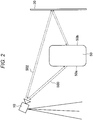
- Figs. 2 to 5 are explanatory diagrams for describing measurement of the object 50 using the specular reflector 20 according to the present embodiment.
- Patent Document 1 discloses a method of measuring the back surface or the like of the object 50 using a plurality of the distance measuring cameras 10 as described above. According to this method, since a plurality of the distance measuring cameras 10 is required, suppression of an increase in cost for constructing the distance measuring system 1 is difficult. Furthermore, in a case of combining images including distance information obtained by the plurality of distance measuring cameras 10 to obtain a three-dimensional image, pieces of point group information acquired by the distance measuring cameras 10 need to be appropriately aligned.
- one distance measuring camera 10 moves around the object 50 and measures the object 50, or the object 50 itself is rotated and measured.
- the measurement takes time, and furthermore, a case where the object 50 dynamically changes over time (for example, the object 50 changes in shape over time) cannot be coped with.
- Fig. 2 which is a diagram of Fig. 1 viewed from a side surface side
- the specular reflector 20 is installed to be perpendicular to the floor surface
- the object 50 is installed between the distance measuring camera 10 and the specular reflector 20.
- an optical axis of the distance measuring camera 10 faces a right direction in Fig. 2 .
- the distance measuring camera 10 irradiates the object 50 with light.
- a part of the emitted light reaches a front surface 50a (the left-side surface in Fig. 2 ) of the object 50, is reflected by the front surface 50a, and is received by the distance measuring camera 10.
- a light path is referred to as a first path 500.
- another part of the emitted light reaches the specular reflector 20, is reflected by the specular reflector 20, and reaches a back surface 50b (the right-side surface in Fig. 2 ) of the object 50.
- the light reaches the specular reflector 20 again and is reflected by the specular reflector 20, and is received by the distance measuring camera 10.
- a second path 502. Such a second path is uniquely determined because the light is specularly reflected.
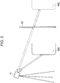
- the distance measuring camera 10 measures the distance from the distance measuring camera 10, reflected by the specular reflector 20, and reaching the object 50, instead of the distance from the distance measuring camera 10 to the specular reflector 20.
- an image of the back surface 50b of the object 50 measured with the light in the second path is measured as if existing beyond the specular reflector 20 by the distance measuring camera 10, as illustrated in Fig. 3 .
- an image observed as if existing beyond the specular reflector 20 is called mirror image 602.
- an image observed to exist on a front side of the specular reflector 20, such as the front surface 50a of the object 50 is called real image 600.
- the above-described real image 600 and mirror image 602 have a mirrored relationship.
- the mirror image 602 is inverted with respect to a plane of the specular reflector 20 as illustrated in Fig. 4 to match the real image 600, whereby a three-dimensional image of the object 50 can be obtained.
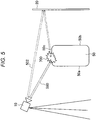
- both the light in the first path 500 and the light in the second path 502 arrive at and by which both the light in the first path 500 and the light in the second path 502 are reflected, depending on the shape of the object 50, like an upper surface 50c of the object 50.
- the light in the first path 500 and the light in the second path 502 are different from each other in phase because the lengths of the paths are different from each other, and the light in the first path 500 and the light in the second path 502 causes an interference 700 on the upper surface 50c of the object 50 or the like.
- the distance measuring camera 10 receives the interference light caused in this way.
- the light received by the distance measuring camera 10 has a phase different from a phase to be originally received due to the interference 700.
- an error occurs in the measured distance, and a correct distance to be originally measured cannot be obtained.
- such a phenomenon is called interference 700 due to multipath.
- the interference 700 due to multipath refers to occurrence of the interference 700 by light in different paths from each other, and is a phenomenon caused by providing the specular reflector 20, although it depends on the shape of the object 50.
- Patent Document 2 since the technology disclosed in Patent Document 2 does not measure the object in consideration of the interference 700 due to multipath described above, it is difficult to accurately measure the distance and shape of the object 50.
- the present inventors have created the embodiment of the present disclosure for enabling accurate measurement of the distance and shape of a region of the object 50, which is difficult to directly measure by one distance measuring camera 10, due to blockage by the object 50 itself or the like.
- the embodiment of the present disclosure described below by providing the specular reflector 20, the distance and shape of the object 50 can be accurately measured even in a case where the interference 700 due to multipath occurs by providing the specular reflector 20.
- the distance measuring system 1 includes the distance measuring camera 10, the specular reflector 20, and the processing device 30.
- the distance measuring camera 10 and the processing device 30 according to the present embodiment will be described.
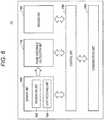
- Fig. 6 is a block diagram illustrating a configuration of the distance measuring camera 10 according to the present embodiment.
- the distance measuring camera 10 mainly includes a sensor unit 100, a phase difference calculation unit 110, an imaging unit (color sensor unit) 120, a control unit 150, and a communication unit 160.
- a sensor unit 100 As illustrated in Fig. 6 , the distance measuring camera 10 mainly includes a sensor unit 100, a phase difference calculation unit 110, an imaging unit (color sensor unit) 120, a control unit 150, and a communication unit 160.
- an imaging unit color sensor unit
- the sensor unit 100 mainly includes an irradiation unit 102 that irradiates the object 50 with light and a light receiving unit 104 that receives (detects) reflected light.
- the irradiation unit 102 includes a laser light source (not illustrated), an optical element (not illustrated), and a photoelectric element (not illustrated).
- a laser diode is used as the laser light source, and the wavelength of emitted light can be changed by appropriately selecting the laser diode.
- description will be given on the assumption that the irradiation unit 102 emits infrared light having a wavelength of about 785 nm.
- a plurality of the laser light sources may be provided in the irradiation unit 102.
- the optical element has a collimator lens and the like, for example, and has a function to emit light from the laser light source as approximately parallel light.
- a light receiving element includes a complementary metal oxide semiconductor (CMOS) image sensor and the like, for example, receives a part of emitted light, and generates a reception light signal on the basis of the intensity of the received light, specifically, a signal approximately proportional to the intensity of the received light. Then, the light receiving element outputs the generated signal to the phase difference calculation unit 110 described below.
- CMOS complementary metal oxide semiconductor
- the laser light source is driven by the control unit 150 described below, and irradiates the object 50 with light. Moreover, the intensity of the light emitted from the laser light source is also controlled by the control unit 150 described below. Furthermore, the irradiation unit 102 may include a light projection mirror (not illustrated), and the like.
- the light receiving unit 104 includes a condenser lens (not illustrated) and a light receiving element (not illustrated).
- the condenser lens has a function to collect the received light to the light receiving element.
- the light receiving element includes a CMOS image sensor having a plurality of pixels and the like, and generates a reception light signal on the basis of the intensity of the received light, specifically, a signal proportional to the intensity of the received light. Therefore, the distance measuring camera 10 can acquire the intensity of light corresponding to each pixel.
- the light receiving element outputs the generated signal to the phase difference calculation unit 110 described below.
- the light receiving unit 104 may be provided with an amplification amplifier (not illustrated) or the like, and may output the generated signal to the phase difference calculation unit 110 after amplifying the signal.
- the light receiving unit 104 may include a light collecting unit (not illustrated) and the like.
- the phase difference calculation unit 110 calculates a phase difference between signals output from the irradiation unit 102 and the light receiving unit 104, in other words, a phase difference between the light emitted from the irradiation unit 102 and the light received by the light receiving unit 104, and outputs the calculated phase difference (sensing data) to the processing device 30 described below. Note that the function of the phase difference calculation unit 110 may be performed by the processing device 30 described below.
- the imaging unit 120 acquires a color captured image of the object 50.
- the imaging unit 120 includes an imaging element (not illustrated) such as a CMOS image sensor and a signal processing circuit (not illustrated) that applies imaging signal processing to a signal photoelectrically converted by the imaging element.
- the above-described imaging element converts incident light from the object 50 as an optical image
- the above-described signal processing circuit photoelectrically converts the focused optical image in units of pixels, reads the signal of each pixel as an imaging signal, processes the image, thereby acquiring the captured image.
- the imaging unit 120 outputs the captured image obtained by imaging to the processing device 30.
- the imaging unit 120 includes an optical system mechanism (not illustrated) configured by an imaging lens, a diaphragm mechanism, a zoom lens, a focus lens, and the like, and a drive system mechanism (not illustrated) that controls the operation of the optical system mechanism.
- the imaging unit 120 may be provided separately from the distance measuring camera 10 as long as the relative position and posture of the distance measuring camera 10 with respect to the sensor unit 100 are known.
- the control unit 150 is, for example, implemented by hardware such as a central processing unit (CPU), a read only memory (ROM), and a random access memory (RAM), and controls the functional units of the distance measuring camera 10.
- CPU central processing unit
- ROM read only memory
- RAM random access memory
- the communication unit 160 is a communication interface having a function to transmit/receive data, and can transmit/receive information to/from an external device such as the processing device 30.
- the communication unit 160 is implemented by a communication port, a communication antenna, and a communication device such as a transmission/reception circuit.
- the distance measuring camera 10 may further include a specular reflector sensor unit (not illustrated) that measures the distance and posture of the specular reflector 20 using ultrasonic waves or the like.
- Fig. 7 is a block diagram illustrating a configuration of the processing device 30 according to the present embodiment.
- the processing device 30 mainly includes a distance calculation unit 300, a correction unit 310, a determination unit 320, an image processing unit 330, a control unit 350, and a communication unit 360. Details of each functional unit of the processing device 30 will be described below.
- the distance calculation unit 300 calculates the distance from the distance measuring camera 10 to the object 50 on the basis of the phase difference output from the above-described distance measuring camera 10.
- the correction unit 310 corrects an error included in the calculated distance, the error being caused by the interference 700 (interference 700 due to multipath) between the light in the first path and the light in the second path. Note that details of the processing of the correction unit 310 will be described below.
- the determination unit 320 determines the presence or absence of occurrence of an error caused by the above-described interference 700 due to multipath. For example, the determination unit 320 determines the presence or absence of occurrence of an error according to the presence or absence of match between the mirror image 602 of the inverted object 50 and the real image 600 of the object 50. Note that details of the processing of the determination unit 320 will be described below.
- the image processing unit 330 acquires a three-dimensional point group of the object 50 on the basis of the distance information for each pixel (point) in the object 50 obtained by the above-described distance calculation unit 300. Furthermore, the image processing unit 330 can also perform inversion processing for a three-dimensional point group of the mirror image 602 of the object 50 on the basis of the position and posture of the specular reflector 20.
- the control unit 350 is implemented by hardware such as a CPU, a ROM, and a RAM, for example, and controls each functional unit of the processing device 30.
- the communication unit 360 is a communication interface having a function to transmit/receive data, and can transmit/receive information to/from an external device such as the distance measuring camera 10.
- the communication unit 360 is implemented by a communication port, a communication antenna, and a communication device such as a transmission/reception circuit, similarly to the above-described communication unit 160.
- Fig. 8 is a flowchart for describing an example of a measurement method according to the present embodiment. As illustrated in Fig. 8 , the measurement method according to the present embodiment includes a plurality of steps from step S101 to step S115. Hereinafter, details of each step included in the measurement method according to the present embodiment will be described.
- the processing device 30 acquires the three-dimensional point group including coordinate information and distance information of each point of the object 50 calculated on the basis of the sensing data from the distance measuring camera 10.
- the processing device 30 confirms whether or not information of the position and posture of the specular reflector 20 viewed from the distance measuring camera 10 has already been acquired.
- the processing device 30 proceeds to step S105 in a case where the information has not already been acquired, and the processing device 30 proceeds to step S107 in a case where the information has already been acquired.
- the processing device 30 acquires the information of the position and posture of the specular reflector 20 viewed from the distance measuring camera 10.
- the distance measuring camera 10 measures the position and posture of the specular reflector 20, and the processing device 30 acquires the measurement result. Note that details of the measurement of the position and posture of the specular reflector 20 will be described below.
- the processing device 30 corrects the error caused by the interference 700 due to multipath caused by providing the specular reflector 20, and acquires the three-dimensional point group of the object 50 to which the correction has been applied. Note that details of the correction will be described below.
- the processing device 30 inverts the three-dimensional point group of the mirror image 602 to which the correction has been applied in step S107 with respect to the plane of the specular reflector 20 to cause the inverted mirror image 602 to match the three-dimensional point group of the real image 600 to which the correction has been applied. Note that, in inverting the mirror image 602, the information of the position and posture of the specular reflector 20 acquired in step S105 is used.
- the processing device 30 determines the presence or absence of the interference 700 due to multipath, for each region (point) of the object 50, on the basis of the presence or absence of match between the real image 600 and the mirror image 602 in step S109.
- the processing device 30 proceeds to step S113 in a case where no occurrence of the interference 700 is determined, and the processing device 30 proceeds to step S115 in a case where occurrence of the interference 700 is determined. Note that details of the determination of the presence or absence of the interference 700 due to multipath will be described below.
- the processing device 30 cancels the correction performed in step S107, and acquires a three-dimensional point group to which correction is not applied.
- the processing device 30 performs the above-described series of steps for all of regions (points) of the object 50, finally acquires a three-dimensional point group of the object 50 not affected by the interference 700 due to multipath, and outputs the three-dimensional point group to the user, or the like, for example.
- the correction has been made according to the presence or absence of the interference 700 due to multipath or the correction has not been made in the three-dimensional point group acquired at this time. Therefore, the real image 600 of the object 50 matches the inverted mirror image 602.
- the alignment is required after a gap is eliminated by an input operation of the user. In the present embodiment, such an input operation is not necessary.
- the presence or absence of interference is determined according to the coincidence of the corrected real image 600 and the mirror image 602.
- the present embodiment is not limited to this method.
- the presence or absence of the interference may be determined according to the match between the real image 600 before correction and the mirror image 602, and whether or not to perform the correction may be selected on the basis of the determination result.
- Fig. 9 is an explanatory diagram for describing an example of a method of measuring the specular reflector 20 according to the present embodiment.
- the distance measuring camera 10 cannot directly measure the distance to the specular reflector 20. Therefore, in the present embodiment, for example, the marker 200 having a less glossy surface is attached to the mirror surface of the specular reflector 20. Then, since the specular reflection does not occur on the surface of such a marker 200, the distance measuring camera 10 can measure the distance to the marker 200, and can therefore measure the position and posture of the specular reflector 20. Note that a method of detecting the marker 200 at this time may be manually selected by the user for a captured image of the marker 200. When the shape of the marker 200 is known, the distance measuring camera 10 may automatically detect the method on the basis of the shape, and is not particularly limited.
- markers 200a having a non-glossy surface are attached along four corners of a surface of a specular reflector 20a.
- the position and posture of the specular reflector 20a can be measured by measuring four markers 200a.
- the marker 200a is not limited to a circular shape and the number of the markers 200a is not limited to four.
- the marker 200 may include three or more markers (marker portions) provided spaced from one another.
- a marker 200b may be a triangle, as illustrated in the center in Fig. 9 .
- the position and posture of the specular reflector 20b can be measured by measuring vertexes of the marker 200b.
- a marker 200c may have a frame-like shape along four corners of a plane of a specular reflector 20c, as illustrated on the right side in Fig. 9 . In this case, the position and posture of the specular reflector 20c can be measured by measuring vertexes of the marker 200c.
- the measurement method is not limited to the above-described method using the marker 200 as long as the position and posture of the specular reflector 20 can be measured by the measurement method.
- the position and posture of the specular reflector 20 may be measured by providing a specular reflector measurement unit (specular reflector sensor unit) that emits ultrasonic waves from the distance measuring camera 10 toward the specular reflector 20.
- the position and posture of the specular reflector 20 may be measured by a motion capture method using a captured image of the specular reflector 20, and the measurement method is not particularly limited.
- the specular reflector 20 and the distance measuring camera 10 are fixed. When relative relationship between the position and posture is known, the above-described marker 200, specular reflector measurement unit, and the like are not necessary.
- the present embodiment it is only required that a relative positional relationship between the distance measuring camera 10 and the specular reflector 20 is known for each imaging frame. Therefore, in the present embodiment, in a case where the relative positional relationship between the distance measuring camera 10 and the specular reflector 20 dynamically changes, it is only required that the relative positional relationship between the distance measuring camera 10 and the specular reflector 20 is acquired using the above-described method for each imaging frame.
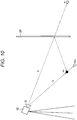
- Fig. 10 is an explanatory diagram for describing an example of a correction method according to the present embodiment.
- Fig. 10 schematically illustrates a positional relationship among a camera center O of the distance measuring camera 10, the specular reflector 20, a position x d of the object 50 to be originally measured by the distance measuring camera 10 (a position of the object 50 to be measured in a case of being not affected by the interference 700 due to multipath), and an observed position x obs of the object 50 including an error caused by the interference 700 due to multipath.
- the light in the first path 500 and the light in the second path 502 cause the interference 700 on the upper surface 50c of the object 50 or the like (interference 700 due to multipath) depending on the shape of the object 50, and the distance measuring camera 10 receives the light having a different phase from a phase to be originally measured.
- an error disortion
- a correct distance of the object 50 cannot be obtained. Therefore, in the present embodiment, a correction of the error caused by the interference 700 due to multipath caused by installing the specular reflector 20 is performed, and the correct distance of the object 50 is acquired.
- the model for estimating the phase obtained in the case where the light in the first path 500 and the light in the second path 502 interfere, in other words, in the case where the interference occurs due to multipath will be described with reference to Fig. 10 .
- the light in the first path 500 and the light in the second path 502 are emitted from the same distance measuring camera 10, the light in the first path 500 and the light in the second path 502 are considered to have the same frequency. Therefore, interference light obtained in the case where an interference occurs due to multipath can be considered to be a combined wave of waveforms having the same frequency and having different phases and amplitudes.
- a phase P i of the interference light at the point x d is expressed by the following expression (1) in a case where the phase of the light in the first path 500 is P d and the phase of the light in the second path 502 is P r at the point of time when the light is emitted from the distance measuring camera 10 and reaches the point xd on the surface of the object 50.
- P d and P r are one-way phases and are ideal phases not affected by the interference 700 due to multipath caused by the specular reflector 20.
- the amplitude of the light in the first path 500 and the amplitude of the light in the second path 502 at the point x d of the object 50 where the light in the first path 500 and the light in the second path 502 interfere are power d and power r , respectively.
- P i tan ⁇ 1 power d sin P d + power r sin P r power d cos P d + power r cos P r
- the path lengths l d and l r followed by the light in the first path 500 and the light in the second path 502 are different. Therefore, since the amplitude (power) of light at a certain point is inversely proportional to the square of the distance from the light source to the point according to the inverse square law, the amplitude of the light in the first path 500 and the amplitude of the light in the second path 502 are different from each other.
- the amplitude power d of the light in the first path 500 and the amplitude power r of the light in the second path 502 at the point x d can be expressed by the following expression (3).
- ⁇ d and ⁇ r represent angles at the point x d made by the normal vector and direction vectors of the light in the first path 500 and the light in the second path 502 having entered the point x d .
- r m in the expression (3) represents the reflectance of the specular reflector 20, and is a constant in a range of 0 ⁇ r m ⁇ 1.
- phase P i of the interference light at the point x d is expressed by the following expression (4) as a function of Pd and Pr by applying the expressions (2) and (3) to the above expression (1).
- A c/2 ⁇ f is established in the expression (4).
- P i tan ⁇ 1 sin P d AP d 2 + rmsin P r AP r 2 cos P d AP d 2 + rmcos P r AP r 2
- the phase P i of the interference light at the point x d can be estimated.
- the interference light interfering at the point x d of the object 50 then reaches the distance measuring camera 10.
- a phase P 0 of the light at the time when the light has reached the distance measuring camera 10 is further shifted by Pd.
- the phase P 0 of the light in the case where the interference light travels following the first path 500 is expressed by the following expression (5).
- phase P 0 of the light observed in the case where the interference 700 occurs due to multipath by installing the specular reflector 20 can be modeled by the expression (5).
- the ideal phases P d and P r observed in the case where no interference 700 due to multipath occurs are obtained.
- the phase including the error caused by the interference 700 due to multipath by installing the specular reflector 20 and observed by the distance measuring camera 10 is P obs .
- the phase P obs is so-called a one-way phase from the camera center O of the distance measuring camera 10 to the point x obs
- the phase P o expressed by the expression (5) is a round-trip phase from the camera center O of the distance measuring camera 10 to the point x obs .
- f 1 (P d , P r ) between the phase P 0 expressed by the model by the above expression (5) and the actually observed phase P obs is expressed by the following expression (6).
- the phase is further shifted by Pr in a case where the interference light follows a path similar to the second path 502, in other words, in a case where the interference light reaches the distance measuring camera 10 from the object 50 via the specular reflector 20.
- a phase P p of the light in the case where the interference light travels following the second path 502 is expressed by the following expression (7). Note that, in this case, the object 50 is observed as if existing at a point x r as viewed from the distance measuring camera 10, in other words, as if the mirror image 602 exists at the point x r . [Math.
- f 2 (P d , P r ) between the phase P p expressed by the model by the above expression (7) and the actually observed phase P obs is expressed by the following expression (8).
- P d and P r can be obtained by minimizing the difference f 1 (P d , P r ) and the difference f 2 (P d , P r ) expressed by the above expressions (6) and (8), in other words, by comparing the phase P obs that is an actual measurement value with an estimation value of the phase estimated to be caused in the case of being affected by the interference 700 due to multipath.
- the distances l d and l r from the camera center O of the distance measuring camera 10 to the point xd can be obtained from P d and P r when the frequency f of the light emitted from the distance measuring camera 10 and the light speed c are known.
- the error caused by the interference 700 due to multipath can be corrected.
- an expression of a straight light passing through the point X obs from the camera center O of the distance measuring camera 10 can be obtained from the information of the three-dimensional point group of the object 50 obtained from the distance measuring camera 10.
- the interference 700 due to multipath caused by installing the specular reflector 20 affects the observed phase, in other words, a distance value, and does not affect the direction in which the light travels.
- the position and posture of the specular reflector 20 are known, the position of the point x r is uniquely determined when the position of the point x d is known. Specifically, the camera center O of the distance measuring camera 10, the point x d , and the point x obs exist on the same straight line.
- the point x r exists at a position symmetrical to the point x d with respect to the plane of the specular reflector 20. Therefore, by obtaining a point where the above expressions (6) and (8) are minimized while scanning the straight line from the camera center O toward the object 50, the position of the ideal observation point x d , in other words, the distance l d can be obtained. Furthermore, since the position of the x r is determined on the basis of the point x d , the distance l r from the camera center O to the point x r can be obtained.
- the interference 700 due to multipath may not occur depending on the shape of the object 50. Furthermore, even in the same object 50, a region where the interference 700 due to multipath occurs and a region where the interference 700 due to multipath does not occur coexist. In such a case, if the above-described correction is performed for all the points of observation data, the region where the interference 700 due to multipath has not occurred is excessively corrected. Therefore, there is a possibility that a three-dimensional point group significantly different from the actual object 50 is acquired. Therefore, in the present embodiment, whether or not the interference 700 due to multipath has occurred, specifically, the region where the interference 700 due to multipath occurs and the region where the interference 700 due to multipath does not occur are discriminated.
- the above-described correction is performed for all the observed three-dimensional point groups including the real image 600 and the mirror image 602.
- the mirror image 602 to which the correction has been applied is inverted with respect to the plane of the specular reflector 20, and the inverted mirror image 602 is caused to match the real image 600 to which the correction has been applied.
- the positions and shapes of the inverted mirror image 602 and the real image 600 match.
- the positions and shapes of the inverted mirror image 602 and the real image 600 do not match due to the excessive correction.
- the three-dimensional point group of the object 50 can be calculated from a distance image including a distance value of each pixel acquired by the distance measuring camera 10.
- the three-dimensional point group can be projected on the two-dimensional distance image. Therefore, in the present embodiment, the three-dimensional point group obtained from the real image 600 of the object 50 and the three-dimensional point group obtained from the mirror image 602 are projected on the distance image.
- each pixel in the three-dimensional point group of the inverted mirror image 602 is treated as a pixel corresponding to a pixel located in the vicinity.
- various storage methods such as nearest neighbor interpolation and bilinear interpolation can be selected, for example. In this way, in the present embodiment, the correspondence between the three-dimensional point group of the real image 600 and the three-dimensional point group of the inverted mirror image 602 is obtained.
- the correction is canceled, estimating that the correspondence cannot be obtained due to the excessive correction, in other words, considering that the interference 700 due to multipath has not occurred at the appropriate point, and the value is replaced with information obtained by adopting a value observed in the distance measuring camera 10 as it is.
- the region where the interference 700 due to multipath occurs and the region where the interference 700 due to multipath does not occur can be discriminated on the basis of the matching state between the three-dimensional point group of the real image 600 and the three-dimensional point group of the inverted mirror image 602.
- a color image obtained by the imaging unit 120 of the distance measuring camera 10 may be used at the above-described discrimination. By doing so, the discrimination of the occurrence of the interference 700 due to multipath can be more easily and accurately performed.
- a relative positional relationship between the sensor unit 100 and the imaging unit 120 of the distance measuring camera 10 are assumed to be known, and camera parameters and the like of the sensor unit 100 and the imaging unit 120 are assumed to be known.
- the correspondence between each pixel of the distance image obtained by the sensor unit 100 and each pixel of the color image obtained by the imaging unit 120 can be specified. Therefore, in the present embodiment, the distance value and color information for each pixel can be acquired. Therefore, in the present embodiment, a color image of the real image 600 and a color image of the mirror image 602 are compared, and a region of the object 50 included in both the color images is specified.
- the region included in both the color images corresponds to both the real image 600 by the light in the first path 500 and the mirror image 602 by the light in the second path 502, a possibility that the region corresponds to the region where the interference 700 due to multipath has occurred is high. Therefore, in the present embodiment, by specifying such a region by the color images and further extracting a three-dimensional point group corresponding to pixels of the specified region, the region where the interference 700 due to multipath has occurred can be acquired. In other words, according to the present embodiment, by referring to the color images, the discrimination of the occurrence of the interference 700 due to multipath can be more easily and accurately performed.
- the discrimination using color images can be performed and supplemented. Therefore, discrimination without leakage with high accuracy can be performed.
- the real image 600 and the inverted mirror image 602 may be estimated to match.
- the characteristic points do not necessarily match in all the pixels. Therefore, in such a case, in the present embodiment, region division by color segmentation is performed for the real image 600 and the inverted mirror image 602 on the basis of the color images acquired by the imaging unit 120.
- the region division is not limited to the color segmentation, and may be performed on the basis of texture or the like obtained from the image of the object 50.
- the method of discriminating the region where the interference 700 due to multipath has occurred is not limited to the above-described method.
- the region may be specified by designating a portion corresponding to the region where the interference 700 due to multipath has occurred from the color image of the object 50 or the like by the user.
- the region may be specified by designating a specific region from regions divided by the color segmentation by the user.
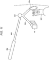
- Fig. 11 is an explanatory diagram for describing an application 1 of the present embodiment, and specifically illustrates a state in which the shape of a dentition 810 in an oral cavity of a patient or the like is scanned using the present embodiment.
- the dentition 810 in dental treatment, in a case of acquiring a denture mold of the patient, it may take time to prepare and cure the material forming the denture mold, which is a burden on the patient. Therefore, if the dentition 810 is directly scanned and a three-dimensional shape of the dentition 810 can be acquired instead of acquiring such a denture mold, the burden on the patient related to the acquisition of the denture mold can be reduced.
- the oral cavity is narrow, and simultaneous insertion of a plurality of cameras for acquiring the three-dimensional shape is difficult. Therefore, it is conceivable to scan the dentition 810 a plurality of times by the cameras, such as scanning one side surface, scanning the other side surface, and further scanning an upper surface, of the dentition 810. However, scanning the dentition 810 a plurality of times also places a heavy burden on the patient.
- an instrument including a small mirror portion (mirror top) and a handle portion (mirror handle), called mirror (dental mirror), is used to observe a region in the oral cavity that is difficult to visually observe from the outside. Therefore, an application such as a monitoring device is conceivable, which scans the dentition 810 once by combining the mirror with the distance measuring camera 10 according to the present embodiment.
- a dental instrument 800 according to application 1 of the embodiment of the present disclosure includes a handle portion 802 for being gripped by a dentist, the distance measuring camera 10, a small mirror portion (specular reflector) 20d. Moreover, the dental instrument 800 includes the fixing member 806 that fixes the distance between the distance measuring camera 10 and the mirror portion 20, and a joint portion 804 that connects the handle portion 802 and the fixing member 806. In the example in Fig. 11 , since the distance between the distance measuring camera 10 and the mirror portion 20d is fixed to a predetermined distance by the fixing member 806, and the posture of the mirror portion 20 is fixed, measurement of the position and posture of the mirror portion 20d is unnecessary.
- the joint portion 804 has a rotatable structure, and the distance measuring camera 10 and the mirror portion 20d are rotated about the joint portion 804 as a rotation axis while mutual relative positions are fixed, so that the dentition 810 (object 50) at various positions can be scanned.
- the intensity of the light emitted by the distance measuring camera 10 is favorably set to a condition suitable for the short distance measurement in order to avoid such saturation.
- the distance between the distance measuring camera 10 and the mirror portion 20d does not need to be fixed as long as the position and posture of the mirror portion 20d can be measured using the marker 200 or the like.
- the distance measuring camera 10 and the mirror portion 20d may be separated or may be made mutually freely movable.
- a plurality of distance measuring cameras 10 is not necessary. Therefore, measurement in a narrow space such as an oral cavity into which the plurality of distance measuring cameras 10 is less easily inserted becomes easy. Furthermore, in treatment or the like where scanning of not only an oral cavity but also various portions in a body of a patient is required, the present embodiment can be applied. Furthermore, the measurement of the position and posture of the mirror portion 20d becomes unnecessary by using the fixing member 806 for fixing the distance between the distance measuring camera 10 and the mirror portion 20d.
- Fig. 12 is an explaining diagram for describing an application 2 of the present embodiment, and illustrates an example of recognizing a gesture of a user who gets on a vehicle 820 using the present embodiment. Note that Fig. 12 illustrates, for the sake of clarity, only a hand (hand gesture) 830 of the user who gets on the vehicle 820, and illustration of the other body parts of the user is omitted.
- the distance measuring camera 10 is installed on a ceiling in the vehicle 820, and the hand gesture 830 is recognized by the distance measuring camera 10.
- the hand gesture 830 such as extending an index finger toward a dashboard 822
- the index finger is hidden behind the back of the hand of the user depending on the position of the distance measuring camera 10 or the direction of the hand of the user.
- the hand gesture 830 with the index finger may not be recognized by the distance measuring camera 10.
- the specular reflector 20 is installed on the dashboard 822, as illustrated in Fig. 12 .
- the distance measuring camera 10 can recognize the hand gesture 830 (object 50) with the index finger blocked by the back of the hand, using the specular reflector 20.
- the specular reflector 20 since the specular reflector 20 is only required to reflect infrared rays emitted from the distance measuring camera 10, for example, the specular reflector 20 may be a film that reflects the infrared rays.
- the embodiment of the present disclosure can be implemented when the position where the mirror image 602 appears is known with respect to the real image 600. Therefore, in the present application, a front window 824 having a known curvature may be used as the specular reflector 20 by attaching a film that reflects infrared rays to the front window 824.
- the distance measuring system 1 is applied to a monitoring device that recognizes the hand gesture 830 in the vehicle.
- the hand gesture 830 with a fingertip or the like which is blocked and cannot be recognized, becomes able to be recognized by the distance measuring camera 10 installed on the ceiling in the vehicle 820. Therefore, according to the present application, a more complicated hand gesture 830 can be discriminated. Therefore, the number of types of discriminable hand gestures 830 can be increased, and more various devices and the like in the vehicle 820 can be easily operated by the user, even with one distance measuring camera 10.
- Fig. 13 is an explanatory diagram for describing an application 3 of the present embodiment, and is specifically an explanatory diagram for describing a three-dimensional monitoring system for scanning movement of a whole body of a person 50d in motion, for example, using the present embodiment.
- the motion tracking device can three-dimensionally scan movement of a person by, for example, attaching a plurality of markers formed using a retroreflecting material to the person, and tracking the movement of the plurality of markers caused by the movement of the person.
- a device is expensive, and the movement of the person may be blocked because the plurality of markers is attached to the person. Therefore, in the present application, the movement of the person is three-dimensionally scanned without attaching the plurality of markers to the person, applying the above-described distance measuring system 1 to the above-described three-dimensional motion monitoring system (monitoring device).
- a large mirror 20e is often provided on one surface of a wall 840 for the person 50d to recognize the movement of the person 50d. Therefore, in the present application, such a large mirror 20e is used as the specular reflector 20.
- the distance measuring camera 10 is installed on a ceiling 842 of the facility or toward the back of the person 50d to be the object 50. Then, by continuously acquiring the real image 600 and the mirror image 602 of the person 50d by the distance measuring camera 10, the movement of the person 50d in motion can be three-dimensionally scanned.
- the distance measuring system 1 can be applied, and the movement of the object 50 (person 50d) can be three-dimensionally scanned with high accuracy.
- the number of the mirrors 20e is not limited to one, and three mirrors 20e surrounding the person 50d as the object 50 may be installed. In this case, not only the front and the back of the person 50d but also a side of the person 50d can be scanned. Note that, at this time, to correct an error caused by the interference 700 due to multipath caused by the plurality of mirrors 20e, the position of each mirror image 602 with respect to the real image 600 is required to be known.
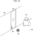
- Fig. 14 is an explanatory diagram for describing an application 4 of the present embodiment, and is specifically an explanatory diagram for describing an environment monitoring system for three-dimensionally scanning an ambient environment of a robot 850 by the robot 850.
- the robot 850 may estimate a self-position of the robot 850 using simultaneous localization and mapping (SLAM) or the like. Moreover, SLAM generates a map around the robot 850 at the same time with self-position estimation.
- SLAM can be implemented by devices such as a stereo camera using parallax, the above-described distance measuring camera 10 of the TOF method, and a laser finder.
- the robot 850 refers to a device that can autonomously move and perform operations and the like.
- a case of using the robot 850 that executes SLAM using the distance measuring camera 10 of the TOF method in a room such as a home or a factory will be considered.
- the distance measuring camera 10 of the TOF method in a case where the specular reflector 20 is present in the surroundings, the interference 700 due to multipath occurs and an error occurs in the measurement of the object 50.
- the large mirror 20e is installed on the wall 840 in the room where the robot 850 moves.
- the distance measuring camera 10 of the robot 850 sometimes recognizes that a floor 860 has a distorted shape caused by the interference 700 due to multipath caused by the mirror 20e even though the floor 860 (object 50) is originally flat. Similarly, the distance measuring camera 10 of the robot 850 cannot correctly recognize the shape of an obstacle 50e (object 50) existing in the room. As a result, the robot 850 may not be able to accurately generate a map around the robot 850.
- the above-described present embodiment is applied as a monitoring device that scans the ambient environment of the robot 850.
- the error caused by the interference 700 due to multipath caused by the mirror 20e can be corrected. Therefore, in the present application, the map around the robot 850 can be accurately generated. Note that, in the above case, it is assumed that the position and posture of the mirror 20e are known.
- a map regarding the space may be generated using two robots 850.
- the distance measuring camera 10 according to the present embodiment is installed in one robot 850
- the specular reflector 20 according to the present embodiment is installed in the other robot 850.
- These two robots 850 move such that the distance measuring camera 10 and the specular reflector 20 face each other, thereby scanning an object or the like in the space, and can generate an accurate map even in the space where a human cannot easily enter.
- the scanning of the object or the like is performed after grasping the relative positional relationship and postures of the robot 850 having the distance measuring camera 10 and the robot 850 having the specular reflector 20.
- the real image 600 and the mirror image 602 of the object 50 can be simultaneously measured by one distance measuring camera 10. Therefore, according to the present embodiment, a region such as the back surface of the object 50, which is difficult to directly measure by one distance measuring camera 10, due to blockage by the object 50 itself or the like, can be measured. Furthermore, according to the present embodiment, since the distance measuring system 1 can be configured by one distance measuring camera 10, an increase in cost for constructing the distance measuring system 1 can be suppressed.
- the front and back of the object 50 can be simultaneously measured by rotationally moving the distance measuring camera 10 around the object 50, or the like.
- measurement cannot be performed in a case where the object 50 dynamically changes over time.
- even such an object 50 can be handled by the single distance measuring camera 10.
- the interference 700 due to multipath occurs due to the installation of the specular reflector 20.
- correction of the error caused by the interference 700 can be performed using the model indicating the phase of light affected by the interference 700. Therefore, according to the present embodiment, the distance and shape of the object 50 can be accurately measured. Furthermore, there are some cases where the region where the interference 700 due to multipath occurs and the region where the interference 700 due to multipath does not occur coexist depending on the shape of the object 50. Even in such a case, according to the present embodiment, the correction can be performed after determining the presence or absence of the occurrence of the interference 700. Therefore, failure of acquisition of an accurate measurement value due to excessive correction for the region that does not require the correction can be avoided.
- Fig. 15 is an explanatory diagram illustrating an example of a hardware configuration of a processing device 900 according to the present embodiment.
- the processing device 900 illustrates an example of a hardware configuration of the above-described processing device 30.
- the processing device 900 includes, for example, a CPU 950, a ROM 952, a RAM 954, a recording medium 956, an input/output interface 958, and an operation input device 960. Moreover, the processing device 900 includes a display device 962, a communication interface 968, and a sensor 980. Furthermore, the processing device 900 has the configuration elements connected with a bus 970 as a data transmission path, for example.
- the CPU 950 includes, for example, one or more processors including an arithmetic circuit such as a CPU, various processing circuits, and the like, and functions as a control unit (for example, the above-described control unit 350) that controls the entire processing device 900.
- the CPU 950 functions as, for example, the distance calculation unit 300, the correction unit 310, the determination unit 320, the image processing unit 330, the control unit 350, and the like in the processing device 900.
- the ROM 952 stores a program and control data such as calculation parameters used by the CPU 950, and the like.
- the RAM 954 temporarily stores the program to be executed by the CPU 950, or the like, for example.
- the recording medium 956 stores, for example, various data such as data related to the measurement method according to the present embodiment and various applications.
- examples of the recording medium 956 include a magnetic recording medium such as a hard disk, and a nonvolatile memory such as a flash memory.
- the recording medium 956 may be attachable to and detachable from the processing device 900.
- the input/output interface 958 connects, for example, the operation input device 960, the display device 962, and the like.
- Examples of the input/output interface 958 include a universal serial bus (USB) terminal, a digital visual interface (DVI) terminal, a high-definition multimedia interface (HDMI) (registered trademark) terminal, various processing circuits, and the like.
- USB universal serial bus
- DVI digital visual interface
- HDMI high-definition multimedia interface
- the operation input device 960 functions as, for example, an input unit that receives a user's operation for the processing device 900, and is connected to the input/output interface 958 inside the processing device 900.
- the display device 962 functions as an output unit that outputs an image or the like to the user, for example, is provided on the processing device 900, and is connected to the input/output interface 958 inside the processing device 900.
- Examples of the display device 962 include a liquid crystal display, an organic electro-luminescence (EL) display, and the like.
- the input/output interface 958 can be connected to an external device such as an operation input device (for example, a keyboard, a mouse, or the like) outside the processing device 900 or an external display device. Furthermore, the input/output interface 958 may be connected to a drive (not illustrated).
- the drive is a reader/writer for a removable recording medium such as a magnetic disk, an optical disk, or a semiconductor memory, and is built in or externally attached to the processing device 900.
- the drive reads information recorded on a mounted removable recording medium and outputs the information to the RAM 954. Furthermore, the drive can also write a record to the mounted removable recording medium.
- the communication interface 968 functions as the communication unit 360 for performing wireless or wired communication with an external device such as the distance measuring camera 10 via the above-described communication cable 60 (or directly), for example.
- examples of the communication interface 968 include a communication antenna and radio frequency (RF) circuit (wireless communication), IEEE802.15.1 port and transmission/reception circuit (wireless communication), IEEE802.11 port and transmission/reception circuit (wireless communication), and a local area network (LAN) terminal, a transmission/reception circuit (wired communication), and the like.
- RF radio frequency
- each of the above-described configuration elements may be configured using general-purpose members or may be configured by hardware specialized for the function of the each configuration element. Such a configuration may be changed as appropriate depending on the level of technology to be implemented.
- the processing device 900 does not need to include the communication interface 968 in a case of communicating with the distance measuring camera 10 or the like via a connected external communication device, or in a case of performing stand-alone processing.
- the communication interface 968 may have a configuration capable of communicating with one or more external devices by a plurality of communication methods.
- the processing device 900 can be configured not to include the recording medium 956, the operation input device 960, the display device 962, and the like, for example.
- the processing device 900 according to the present embodiment may be a system including a plurality of devices on the premise of connection to a network (or communication between devices) such as cloud computing, for example. That is, the processing device 900 according to the above-described present embodiment can be implemented as a processing system that performs processing according to the measurement method according to the present embodiment using a plurality of devices, for example.
- the steps in the measurement method according to the above-described embodiment do not necessarily need to be processed in the described order.
- the steps may be processed in an appropriately changed order.
- the steps may be partially processed in parallel or individually processed instead of being chronologically processed.
- the steps do not necessarily need to be processed in accordance with the described method, and may be processed by another method using another functional block, for example.
- At least a part of the measurement method according to the above-described embodiment can be configured by software as an information processing program for causing a computer (processing device 30 or 900) to function.
- a program that implements at least a part of the method may be stored in a recording medium and read and executed by the processing device 30 (900) and the like, or by another device connected to the processing device 30 (900).
- a program that implements at least a part of the processing method may be distributed via a communication line (including wireless communication) such as the Internet.
- the program may be distributed via a wired line or a wireless line such as the Internet, or stored in a recording medium, in a state of being encrypted, modulated, or compressed.
Landscapes
- Physics & Mathematics (AREA)
- Engineering & Computer Science (AREA)
- Health & Medical Sciences (AREA)
- General Physics & Mathematics (AREA)
- Life Sciences & Earth Sciences (AREA)
- Electromagnetism (AREA)
- General Health & Medical Sciences (AREA)
- Computer Networks & Wireless Communication (AREA)
- Radar, Positioning & Navigation (AREA)
- Remote Sensing (AREA)
- Theoretical Computer Science (AREA)
- Dentistry (AREA)
- Epidemiology (AREA)
- Animal Behavior & Ethology (AREA)
- Public Health (AREA)
- Veterinary Medicine (AREA)
- Oral & Maxillofacial Surgery (AREA)
- Optics & Photonics (AREA)
- Immunology (AREA)
- Pathology (AREA)
- Chemical & Material Sciences (AREA)
- Analytical Chemistry (AREA)
- Biochemistry (AREA)
- Computer Vision & Pattern Recognition (AREA)
- Data Mining & Analysis (AREA)
- Mathematical Physics (AREA)
- Spectroscopy & Molecular Physics (AREA)
- Quality & Reliability (AREA)
- Bioinformatics & Cheminformatics (AREA)
- Evolutionary Biology (AREA)
- Evolutionary Computation (AREA)
- General Engineering & Computer Science (AREA)
- Bioinformatics & Computational Biology (AREA)
- Artificial Intelligence (AREA)
- Multimedia (AREA)
- Signal Processing (AREA)
- Length Measuring Devices By Optical Means (AREA)
- Optical Radar Systems And Details Thereof (AREA)
- Measurement Of Optical Distance (AREA)
Abstract
Description
- The present disclosure relates to an imaging device and a monitoring device.
- Distance measuring cameras that emit infrared light or the like to an object and receive the infrared light reflected by the object to measure a distance to the object or a surface shape of the object are known. An example of such a distance measuring camera includes a technology disclosed in
Patent Document 1 below. - By the way, when trying to measure an object with the distance measuring camera, there may be a region that cannot be measured by one distance measuring camera, specifically, a back surface that cannot be directly measured due to blockage by the object itself, or the like. In such a case, it is conceivable to measure the back surface of the object or the like using one distance measuring camera and a specular reflector in combination. As such a method, a technology disclosed in Patent Document 2 below can be cited, for example.
-
- Patent Document 1: Japanese Patent Application Laid-Open No.
2012-57960 - Patent Document 2: Japanese
PCT National Publication No. 2012-509470 - By the way, in the case of measuring the object using the specular reflector, there are two paths of light. The light in the first path is light that reaches the object from the distance measuring camera, is directly reflected by the object, and returns to the distance measuring camera. Meanwhile, the light in the second path reaches the specular reflector from the distance measuring camera, is reflected by the specular reflector, reaches the object, and further returns from the object to the distance measuring camera via the specular reflector in the same path. In addition to that, the light from these two different paths may interfere on the same point (surface) of the object (this phenomenon is called interference due to multipath) depending on the shape of the object. In some cases, the distance measuring camera may not be able to correctly measure the distance and shape of the object due to reception of interference light. However, since the technology disclosed in Patent Document 2 does not measure the object in consideration of the interference due to multipath as described above, it is difficult to accurately measure the distance and shape of the object.
- Therefore, the present disclosure proposes, in view of the foregoing, new and improved imaging device and monitoring device capable of accurately measuring a distance and a shape of a region of an object that is difficult to directly measure by one distance measuring camera.
- According to the present disclosure, provided is an imaging device including: a sensor unit configured to irradiate an object with light and detect the light reflected by the object; a distance calculation unit configured to calculate a distance to the object on the basis of sensing data of the sensor unit; a specular reflector located on an opposite side of the sensor unit across the object; and a correction unit configured to correct an error included in the calculated distance, the error being caused by an interference between the light following a first path from the sensor unit toward the object and the light following a second path from the sensor unit, reflected by the specular reflector, and going toward the object.
- Furthermore, according to the present disclosure, provided is an imaging device including: a sensor unit configured to irradiate an object with light and detect the light reflected by the object; a distance calculation unit configured to calculate a distance to the object on the basis of sensing data of the sensor unit; and a correction unit configured to correct an error included in the calculated distance, the error being caused by an interference between the light following a first path from the sensor unit toward the object and the light following a second path from the sensor unit, reflected by a specular reflector located on an opposite side of the sensor unit across the object, and going toward the object.
- Furthermore, according to the present disclosure, provided is a monitoring device having an imaging device mounted, the imaging device including: a sensor unit configured to irradiate an object with light and detect the light reflected by the object; a distance calculation unit configured to calculate a distance to the object on the basis of sensing data of the sensor unit; and a correction unit configured to correct an error included in the calculated distance, the error being caused by an interference between the light following a first path from the sensor unit toward the object and the light following a second path from the sensor unit, reflected by a specular reflector located on an opposite side of the sensor unit across the object, and going toward the object.
- As described above, according to the present disclosure, an imaging device and a monitoring device capable of accurately measuring a distance and a shape of a region of an object that is difficult to measure by one distance measuring camera can be provided.
- Note that the above-described effect is not necessarily limited, and any of effects described in the present specification or other effects that can be grasped from the present specification may be exerted in addition to or in place of the above-described effect.
-
-
Fig. 1 is a diagram illustrating a configuration example of adistance measuring system 1 according to an embodiment of the present disclosure. -
Fig. 2 is an explanatory diagram (part 1) for describing measurement of anobject 50 using aspecular reflector 20 according to the embodiment. -
Fig. 3 is an explanatory diagram (part 2) for describing the measurement of theobject 50 using thespecular reflector 20 according to the embodiment. -
Fig. 4 is an explanatory diagram (part 3) for describing the measurement of theobject 50 using thespecular reflector 20 according to the embodiment. -
Fig. 5 is an explanatory diagram (part 4) for describing the measurement of theobject 50 using thespecular reflector 20 according to the embodiment. -
Fig. 6 is a block diagram illustrating a configuration of adistance measuring camera 10 according to the embodiment. -
Fig. 7 is a block diagram illustrating a configuration of aprocessing device 30 according to the embodiment. -
Fig. 8 is a flowchart for describing an example of a measurement method according to the embodiment. -
Fig. 9 is an explanatory diagram for describing an example of a method of measuring thespecular reflector 20 according to the embodiment. -
Fig. 10 is an explanatory diagram for describing an example of a correction method according to the embodiment. -
Fig. 11 is an explanatory diagram for describing anapplication 1 of the embodiment. -
Fig. 12 is an explanatory diagram for describing an application 2 of the embodiment. -
Fig. 13 is an explanatory diagram for describing an application 3 of the embodiment. -
Fig. 14 is an explanatory diagram for describing an application 4 of the embodiment. -
Fig. 15 is an explanatory diagram illustrating an example of a hardware configuration of aprocessing device 900 according to the embodiment. - Favorable embodiments of the present disclosure will be described in detail with reference to the appended drawings. Note that, in the present specification and drawings, overlapping description of configuration elements having substantially the same functional configuration is omitted by providing the same sign.
- Note that the description will be given in the following order.
- 1. Outline of
Distance Measuring System 1 According to Embodiment of Present Disclosure - 2. Background Leading to Creation of Embodiment According to Present Disclosure by Inventors
- 3. Details of Each Device Included in
Distance Measuring System 1 According to Embodiment of Present Disclosure- 3.1 Detailed Configuration of Distance Measuring
Camera 10 - 3.2 Detailed Configuration of
Processing Device 30
- 3.1 Detailed Configuration of Distance Measuring
- 4. Measurement Method According to Embodiment of Present Disclosure
- 4.1 Measurement of Specular Reflector
- 4.2 Correction of Error Due to Multipath Interference
- 4.3 Determining of Presence or Absence of Occurrence of Multipath
- 5. Application of Embodiment of Present Disclosure
- 5.1
Application 1 - 5.2 Application 2
- 5.3 Application 3
- 5.4 Application 4
- 5.1
- 6. Conclusion
- 7. Hardware Configuration
- 8. Supplement
- First, an outline of a distance measuring system (imaging device) 1 according to an embodiment of the present disclosure will be described with reference to
Fig. 1. Fig. 1 is a diagram illustrating a configuration example of thedistance measuring system 1 according to the present embodiment. As illustrated inFig. 1 , thedistance measuring system 1 according to the present embodiment includes adistance measuring camera 10, aspecular reflector 20, and aprocessing device 30. Furthermore, inFig. 1 , anobject 50 for which the distance is measured is illustrated, and thedistance measuring camera 10 and thespecular reflector 20 are arranged to face each other across theobject 50. In other words, thespecular reflector 20 is located on the opposite side of thedistance measuring camera 10 across theobject 50. Thedistance measuring system 1 according to the embodiment of the present disclosure can capture, for example, a surface of theobject 50 with thedistance measuring camera 10, the surface corresponding to a back surface as viewed from thedistance measuring camera 10, by using thespecular reflector 20 even if there is only onedistance measuring camera 10. Note that, inFig. 1 , thespecular reflector 20 is assumed to have a planar shape and be installed such that a mirror surface of thespecular reflector 20 is orthogonal to a floor surface. Hereinafter, an outline of each device included in thedistance measuring system 1 will be described. - The
distance measuring camera 10 according to the present embodiment is a distance measuring device that measures the distance and shape (depth) of theobject 50 using infrared light or the like. Specifically, for example, thedistance measuring camera 10 emits irradiation light to theobject 50, receives reflection light reflected by theobject 50, and detects a phase difference between the irradiation light and the reflection light, thereby measuring the distance and shape of theobject 50. Such a distance measuring method is called indirect time of flight (TOF) method. This method is suitable when, for example, measuring theobject 50 at a distance of up to about 3 m indoors, or the like. - Furthermore, in the present embodiment, the
distance measuring camera 10 may detect a round-trip time of light from when having emitted the irradiation light to when the emission light is received as the reflection light after reflected by theobject 50, thereby measuring the distance and shape of theobject 50. Such a distance measuring method is called direct TOF method. This method is suitable when, for example, measuring theobject 50 located at a distance of up to about 5 m outdoors or the like. Furthermore, thedistance measuring camera 10 may be a device that measures the distance (depth) to theobject 50 by a structured light method. The structured light method is a method of projecting light having a predetermined pattern on a surface of theobject 50 and analyzing deformation of a projected light pattern, thereby estimating the distance to theobject 50. - Note that the following description will be given on the assumption that the
distance measuring camera 10 is a distance measuring camera compatible with the indirect TOF method. Moreover, thedistance measuring camera 10 is assumed to include an imaging unit 120 (seeFig. 6 ) for imaging theobject 50, and the like. Furthermore, a detailed configuration of thedistance measuring camera 10 will be described below. - The
specular reflector 20 has a surface for specularly reflecting light, which is, for example, a surface made using a metal such as silver or aluminum, a metal film, or the like. Furthermore, in a case where the light emitted from the above-describeddistance measuring camera 10 is infrared rays, thespecular reflector 20 may be a film that reflects the infrared rays. - As illustrated in
Fig. 1 , thespecular reflector 20 is installed to face thedistance measuring camera 10 across theobject 50. Note that, in the present embodiment, the distance between a mirror surface of thespecular reflector 20 and thedistance measuring camera 10 and the posture of thespecular reflector 20 are assumed to be known before the distance of theobject 50 is measured or are assumed to be measured. Furthermore, in the present embodiment, a fixing member 806 (seeFig. 11 ) for fixing thedistance measuring camera 10 and thespecular reflector 20 may be provided to fix thespecular reflector 20 at a known distance, for example. Moreover, in the present embodiment, amarker 200 may be provided on the mirror surface to measure the distance and posture of thespecular reflector 20. Note that details of the fixingmember 806 and themarker 200 will be described below. - Furthermore, in a case where a mirror or the like is installed in advance as the
specular reflector 20 on a wall 840 (seeFig. 13 ) of a space where measurement is performed, thespecular reflector 20 may not be included in thedistance measuring system 1 according to the present embodiment. - The
processing device 30 is a device that calculates the distance and shape of theobject 50 on the basis of a phase difference detected by thedistance measuring camera 10. Theprocessing device 30 is a terminal such as a personal computer (PC), a tablet PC, or a personal digital assistant (PDA), for example, and an application for implementing the present embodiment is mounted therein. As illustrated inFig. 1 , theprocessing device 30 is connected with thedistance measuring camera 10 via acommunication cable 60 to receive sensing data from thedistance measuring camera 10. Note that, in the present embodiment, connection between theprocessing device 30 and thedistance measuring camera 10 is not limited to the wired connection as illustrated inFig. 1 , and may be connection via wireless communication. - Furthermore, in the present embodiment, the processing in the
processing device 30 may be performed by thedistance measuring camera 10, in other words, the processing may be performed by thedistance measuring camera 10 in a stand-alone manner. Furthermore, for example, theprocessing device 30 according to the present embodiment may be a system including a plurality of devices on the premise of connection to a network such as cloud computing. - Next, before describing details of an embodiment according to the present disclosure, the background leading to creation of the embodiment according to the present disclosure by the inventors will be described with reference to
Figs. 2 to 5. Figs. 2 to 5 are explanatory diagrams for describing measurement of theobject 50 using thespecular reflector 20 according to the present embodiment. - For example, in a case where a region (for example, a back surface of the object 50) that cannot be measured by one
distance measuring camera 10 is present in theobject 50 to be measured by thedistance measuring camera 10, a plurality of thedistance measuring cameras 10 is required. For example,Patent Document 1 discloses a method of measuring the back surface or the like of theobject 50 using a plurality of thedistance measuring cameras 10 as described above. According to this method, since a plurality of thedistance measuring cameras 10 is required, suppression of an increase in cost for constructing thedistance measuring system 1 is difficult. Furthermore, in a case of combining images including distance information obtained by the plurality ofdistance measuring cameras 10 to obtain a three-dimensional image, pieces of point group information acquired by thedistance measuring cameras 10 need to be appropriately aligned. Therefore, parts of the region measured by the plurality ofdistance measuring cameras 10 are required to overlap one another. As a result, there is a restriction on installation positions of thedistance measuring cameras 10 in the technology disclosed inPatent Document 1, and thus measurement of theobject 50 while following the freely movingobject 50 is not easy. Furthermore, in the technology disclosed inPatent Document 1, the plurality ofdistance measuring cameras 10 needs to be synchronized with one another to avoid an interference among thedistance measuring cameras 10. - To suppress the increase in cost, it is conceivable that one
distance measuring camera 10 moves around theobject 50 and measures theobject 50, or theobject 50 itself is rotated and measured. In such a case, the measurement takes time, and furthermore, a case where theobject 50 dynamically changes over time (for example, theobject 50 changes in shape over time) cannot be coped with. - Furthermore, it is conceivable to measure the region that cannot be measured by the
distance measuring camera 10, using onedistance measuring camera 10 and thespecular reflector 20 in combination. As such a method, the technology disclosed in Patent Document 2 can be cited. Specifically, as illustrated inFig. 2 , which is a diagram ofFig. 1 viewed from a side surface side, thespecular reflector 20 is installed to be perpendicular to the floor surface, and theobject 50 is installed between thedistance measuring camera 10 and thespecular reflector 20. At this time, an optical axis of thedistance measuring camera 10 faces a right direction inFig. 2 . Then, thedistance measuring camera 10 irradiates theobject 50 with light. A part of the emitted light reaches afront surface 50a (the left-side surface inFig. 2 ) of theobject 50, is reflected by thefront surface 50a, and is received by thedistance measuring camera 10. Note that, in the following description, such a light path is referred to as afirst path 500. Meanwhile, another part of the emitted light reaches thespecular reflector 20, is reflected by thespecular reflector 20, and reaches aback surface 50b (the right-side surface inFig. 2 ) of theobject 50. Moreover, after the light is reflected by theback surface 50b of theobject 50, the light reaches thespecular reflector 20 again and is reflected by thespecular reflector 20, and is received by thedistance measuring camera 10. Note that, in the following description, such a light path is referred to as asecond path 502. Such a second path is uniquely determined because the light is specularly reflected. - Therefore, in the case of measuring the distance of the
back surface 50b of theobject 50, thedistance measuring camera 10 measures the distance from thedistance measuring camera 10, reflected by thespecular reflector 20, and reaching theobject 50, instead of the distance from thedistance measuring camera 10 to thespecular reflector 20. - Then, an image of the
back surface 50b of theobject 50 measured with the light in the second path is measured as if existing beyond thespecular reflector 20 by thedistance measuring camera 10, as illustrated inFig. 3 . Note that, in the following description, an image observed as if existing beyond thespecular reflector 20 is calledmirror image 602. Furthermore, in the following description, an image observed to exist on a front side of thespecular reflector 20, such as thefront surface 50a of theobject 50, is calledreal image 600. - In other words, the above-described
real image 600 andmirror image 602 have a mirrored relationship. At this time, if the position and posture of thespecular reflector 20 are known as viewed from thedistance measuring camera 10, themirror image 602 is inverted with respect to a plane of thespecular reflector 20 as illustrated inFig. 4 to match thereal image 600, whereby a three-dimensional image of theobject 50 can be obtained. - By the way, as illustrated in
Fig. 5 , there may be a surface that both the light in thefirst path 500 and the light in thesecond path 502 arrive at and by which both the light in thefirst path 500 and the light in thesecond path 502 are reflected, depending on the shape of theobject 50, like anupper surface 50c of theobject 50. The light in thefirst path 500 and the light in thesecond path 502 are different from each other in phase because the lengths of the paths are different from each other, and the light in thefirst path 500 and the light in thesecond path 502 causes aninterference 700 on theupper surface 50c of theobject 50 or the like. As a result, thedistance measuring camera 10 receives the interference light caused in this way. Therefore, the light received by thedistance measuring camera 10 has a phase different from a phase to be originally received due to theinterference 700. As a result, an error (distortion) occurs in the measured distance, and a correct distance to be originally measured cannot be obtained. Note that, in the following description, such a phenomenon is calledinterference 700 due to multipath. In other words, in the following description, theinterference 700 due to multipath refers to occurrence of theinterference 700 by light in different paths from each other, and is a phenomenon caused by providing thespecular reflector 20, although it depends on the shape of theobject 50. - However, as described above, since the technology disclosed in Patent Document 2 does not measure the object in consideration of the
interference 700 due to multipath described above, it is difficult to accurately measure the distance and shape of theobject 50. - Therefore, in view of the foregoing, the present inventors have created the embodiment of the present disclosure for enabling accurate measurement of the distance and shape of a region of the
object 50, which is difficult to directly measure by onedistance measuring camera 10, due to blockage by theobject 50 itself or the like. Specifically, according to the embodiment of the present disclosure described below, by providing thespecular reflector 20, the distance and shape of theobject 50 can be accurately measured even in a case where theinterference 700 due to multipath occurs by providing thespecular reflector 20. Hereinafter, details of the embodiment of the present disclosure will be sequentially described in detail. - Next, details of each device included in the
distance measuring system 1 according to the embodiment of the present disclosure will be described. Specifically, as described above, thedistance measuring system 1 according to the present embodiment includes thedistance measuring camera 10, thespecular reflector 20, and theprocessing device 30. Hereinafter, details of thedistance measuring camera 10 and theprocessing device 30 according to the present embodiment will be described. - First, a detailed configuration of the
distance measuring camera 10 will be described with reference toFig. 6. Fig. 6 is a block diagram illustrating a configuration of thedistance measuring camera 10 according to the present embodiment. As illustrated inFig. 6 , thedistance measuring camera 10 mainly includes asensor unit 100, a phasedifference calculation unit 110, an imaging unit (color sensor unit) 120, acontrol unit 150, and acommunication unit 160. Hereinafter, details of each functional unit of thedistance measuring camera 10 will be described. - The
sensor unit 100 mainly includes anirradiation unit 102 that irradiates theobject 50 with light and alight receiving unit 104 that receives (detects) reflected light. - Specifically, the
irradiation unit 102 includes a laser light source (not illustrated), an optical element (not illustrated), and a photoelectric element (not illustrated). For example, a laser diode is used as the laser light source, and the wavelength of emitted light can be changed by appropriately selecting the laser diode. Note that, in the present embodiment, description will be given on the assumption that theirradiation unit 102 emits infrared light having a wavelength of about 785 nm. Furthermore, a plurality of the laser light sources may be provided in theirradiation unit 102. Furthermore, the optical element has a collimator lens and the like, for example, and has a function to emit light from the laser light source as approximately parallel light. Furthermore, a light receiving element includes a complementary metal oxide semiconductor (CMOS) image sensor and the like, for example, receives a part of emitted light, and generates a reception light signal on the basis of the intensity of the received light, specifically, a signal approximately proportional to the intensity of the received light. Then, the light receiving element outputs the generated signal to the phasedifference calculation unit 110 described below. - Note that the laser light source is driven by the
control unit 150 described below, and irradiates theobject 50 with light. Moreover, the intensity of the light emitted from the laser light source is also controlled by thecontrol unit 150 described below. Furthermore, theirradiation unit 102 may include a light projection mirror (not illustrated), and the like. - The
light receiving unit 104 includes a condenser lens (not illustrated) and a light receiving element (not illustrated). The condenser lens has a function to collect the received light to the light receiving element. Furthermore, for example, the light receiving element includes a CMOS image sensor having a plurality of pixels and the like, and generates a reception light signal on the basis of the intensity of the received light, specifically, a signal proportional to the intensity of the received light. Therefore, thedistance measuring camera 10 can acquire the intensity of light corresponding to each pixel. Moreover, the light receiving element outputs the generated signal to the phasedifference calculation unit 110 described below. At this time, thelight receiving unit 104 may be provided with an amplification amplifier (not illustrated) or the like, and may output the generated signal to the phasedifference calculation unit 110 after amplifying the signal. Note that thelight receiving unit 104 may include a light collecting unit (not illustrated) and the like. - The phase
difference calculation unit 110 calculates a phase difference between signals output from theirradiation unit 102 and thelight receiving unit 104, in other words, a phase difference between the light emitted from theirradiation unit 102 and the light received by thelight receiving unit 104, and outputs the calculated phase difference (sensing data) to theprocessing device 30 described below. Note that the function of the phasedifference calculation unit 110 may be performed by theprocessing device 30 described below. - The
imaging unit 120 acquires a color captured image of theobject 50. Specifically, theimaging unit 120 includes an imaging element (not illustrated) such as a CMOS image sensor and a signal processing circuit (not illustrated) that applies imaging signal processing to a signal photoelectrically converted by the imaging element. The above-described imaging element converts incident light from theobject 50 as an optical image, and the above-described signal processing circuit photoelectrically converts the focused optical image in units of pixels, reads the signal of each pixel as an imaging signal, processes the image, thereby acquiring the captured image. For example, theimaging unit 120 outputs the captured image obtained by imaging to theprocessing device 30. Moreover, theimaging unit 120 includes an optical system mechanism (not illustrated) configured by an imaging lens, a diaphragm mechanism, a zoom lens, a focus lens, and the like, and a drive system mechanism (not illustrated) that controls the operation of the optical system mechanism. Note that theimaging unit 120 may be provided separately from thedistance measuring camera 10 as long as the relative position and posture of thedistance measuring camera 10 with respect to thesensor unit 100 are known. - The
control unit 150 is, for example, implemented by hardware such as a central processing unit (CPU), a read only memory (ROM), and a random access memory (RAM), and controls the functional units of thedistance measuring camera 10. - The
communication unit 160 is a communication interface having a function to transmit/receive data, and can transmit/receive information to/from an external device such as theprocessing device 30. Thecommunication unit 160 is implemented by a communication port, a communication antenna, and a communication device such as a transmission/reception circuit. - Note that the
distance measuring camera 10 may further include a specular reflector sensor unit (not illustrated) that measures the distance and posture of thespecular reflector 20 using ultrasonic waves or the like. - Next, a detailed configuration of the
processing device 30 will be described with reference toFig. 7. Fig. 7 is a block diagram illustrating a configuration of theprocessing device 30 according to the present embodiment. As illustrated inFig. 7 , theprocessing device 30 mainly includes adistance calculation unit 300, acorrection unit 310, adetermination unit 320, animage processing unit 330, acontrol unit 350, and acommunication unit 360. Details of each functional unit of theprocessing device 30 will be described below. - The
distance calculation unit 300 calculates the distance from thedistance measuring camera 10 to theobject 50 on the basis of the phase difference output from the above-describeddistance measuring camera 10. - The
correction unit 310 corrects an error included in the calculated distance, the error being caused by the interference 700 (interference 700 due to multipath) between the light in the first path and the light in the second path. Note that details of the processing of thecorrection unit 310 will be described below. - The
determination unit 320 determines the presence or absence of occurrence of an error caused by the above-describedinterference 700 due to multipath. For example, thedetermination unit 320 determines the presence or absence of occurrence of an error according to the presence or absence of match between themirror image 602 of theinverted object 50 and thereal image 600 of theobject 50. Note that details of the processing of thedetermination unit 320 will be described below. - The
image processing unit 330 acquires a three-dimensional point group of theobject 50 on the basis of the distance information for each pixel (point) in theobject 50 obtained by the above-describeddistance calculation unit 300. Furthermore, theimage processing unit 330 can also perform inversion processing for a three-dimensional point group of themirror image 602 of theobject 50 on the basis of the position and posture of thespecular reflector 20. - The
control unit 350 is implemented by hardware such as a CPU, a ROM, and a RAM, for example, and controls each functional unit of theprocessing device 30. - The
communication unit 360 is a communication interface having a function to transmit/receive data, and can transmit/receive information to/from an external device such as thedistance measuring camera 10. Thecommunication unit 360 is implemented by a communication port, a communication antenna, and a communication device such as a transmission/reception circuit, similarly to the above-describedcommunication unit 160. - The details of each device included in the
distance measuring system 1 according to the embodiment of the present disclosure have been described above. Next, the measurement method according to the present embodiment will be described with reference toFig. 8. Fig. 8 is a flowchart for describing an example of a measurement method according to the present embodiment. As illustrated inFig. 8 , the measurement method according to the present embodiment includes a plurality of steps from step S101 to step S115. Hereinafter, details of each step included in the measurement method according to the present embodiment will be described. - First, the
processing device 30 acquires the three-dimensional point group including coordinate information and distance information of each point of theobject 50 calculated on the basis of the sensing data from thedistance measuring camera 10. - Next, the
processing device 30 confirms whether or not information of the position and posture of thespecular reflector 20 viewed from thedistance measuring camera 10 has already been acquired. Theprocessing device 30 proceeds to step S105 in a case where the information has not already been acquired, and theprocessing device 30 proceeds to step S107 in a case where the information has already been acquired. - The
processing device 30 acquires the information of the position and posture of thespecular reflector 20 viewed from thedistance measuring camera 10. For example, thedistance measuring camera 10 measures the position and posture of thespecular reflector 20, and theprocessing device 30 acquires the measurement result. Note that details of the measurement of the position and posture of thespecular reflector 20 will be described below. - Next, the
processing device 30 corrects the error caused by theinterference 700 due to multipath caused by providing thespecular reflector 20, and acquires the three-dimensional point group of theobject 50 to which the correction has been applied. Note that details of the correction will be described below. - The
processing device 30 inverts the three-dimensional point group of themirror image 602 to which the correction has been applied in step S107 with respect to the plane of thespecular reflector 20 to cause theinverted mirror image 602 to match the three-dimensional point group of thereal image 600 to which the correction has been applied. Note that, in inverting themirror image 602, the information of the position and posture of thespecular reflector 20 acquired in step S105 is used. - The
processing device 30 determines the presence or absence of theinterference 700 due to multipath, for each region (point) of theobject 50, on the basis of the presence or absence of match between thereal image 600 and themirror image 602 in step S109. Theprocessing device 30 proceeds to step S113 in a case where no occurrence of theinterference 700 is determined, and theprocessing device 30 proceeds to step S115 in a case where occurrence of theinterference 700 is determined. Note that details of the determination of the presence or absence of theinterference 700 due to multipath will be described below. - The
processing device 30 cancels the correction performed in step S107, and acquires a three-dimensional point group to which correction is not applied. - The
processing device 30 performs the above-described series of steps for all of regions (points) of theobject 50, finally acquires a three-dimensional point group of theobject 50 not affected by theinterference 700 due to multipath, and outputs the three-dimensional point group to the user, or the like, for example. Note that the correction has been made according to the presence or absence of theinterference 700 due to multipath or the correction has not been made in the three-dimensional point group acquired at this time. Therefore, thereal image 600 of theobject 50 matches theinverted mirror image 602. In the past, there have been cases where, in the alignment of thereal image 600 with theinverted mirror image 602, the alignment is required after a gap is eliminated by an input operation of the user. In the present embodiment, such an input operation is not necessary. Furthermore, in the past, there have been cases where, in the alignment of thereal image 600 with theinverted mirror image 602, a common region commonly observed in both thereal image 600 and themirror image 602 is provided, and the alignment based on the common region is required. In the present embodiment, such an operation is not necessary. - Note that, in the measurement method illustrated in
Fig. 8 , the presence or absence of interference is determined according to the coincidence of the correctedreal image 600 and themirror image 602. However, the present embodiment is not limited to this method. For example, in the present embodiment, the presence or absence of the interference may be determined according to the match between thereal image 600 before correction and themirror image 602, and whether or not to perform the correction may be selected on the basis of the determination result. - Hereinafter, details of the measurement of the position and posture of the
specular reflector 20 in step S105, details of the correction in step S107, and details of the determination of the presence or absence of the error in step S111 will be described in order. - First, details of the measurement of the position and posture of the
specular reflector 20 in step S105 will be described with reference toFig. 9. Fig. 9 is an explanatory diagram for describing an example of a method of measuring thespecular reflector 20 according to the present embodiment. - By the way, since specular reflection is caused on a mirror surface of the
specular reflector 20, incident light entering thespecular reflector 20 and reflection light reflected by thespecular reflector 20 do not follow the same path. Therefore, thedistance measuring camera 10 cannot directly measure the distance to thespecular reflector 20. Therefore, in the present embodiment, for example, themarker 200 having a less glossy surface is attached to the mirror surface of thespecular reflector 20. Then, since the specular reflection does not occur on the surface of such amarker 200, thedistance measuring camera 10 can measure the distance to themarker 200, and can therefore measure the position and posture of thespecular reflector 20. Note that a method of detecting themarker 200 at this time may be manually selected by the user for a captured image of themarker 200. When the shape of themarker 200 is known, thedistance measuring camera 10 may automatically detect the method on the basis of the shape, and is not particularly limited. - Specifically, as illustrated on the left side in
Fig. 9 ,markers 200a having a non-glossy surface are attached along four corners of a surface of aspecular reflector 20a. In this case, the position and posture of thespecular reflector 20a can be measured by measuring fourmarkers 200a. Note that, as illustrated on the left side inFig. 9 , themarker 200a is not limited to a circular shape and the number of themarkers 200a is not limited to four. For example, in the present embodiment, themarker 200 may include three or more markers (marker portions) provided spaced from one another. - Furthermore, in the present embodiment, a
marker 200b may be a triangle, as illustrated in the center inFig. 9 . In this case, the position and posture of thespecular reflector 20b can be measured by measuring vertexes of themarker 200b. Moreover, in the present embodiment, amarker 200c may have a frame-like shape along four corners of a plane of aspecular reflector 20c, as illustrated on the right side inFig. 9 . In this case, the position and posture of thespecular reflector 20c can be measured by measuring vertexes of themarker 200c. - Furthermore, in the present embodiment, the measurement method is not limited to the above-described method using the
marker 200 as long as the position and posture of thespecular reflector 20 can be measured by the measurement method. For example, according to the present embodiment, the position and posture of thespecular reflector 20 may be measured by providing a specular reflector measurement unit (specular reflector sensor unit) that emits ultrasonic waves from thedistance measuring camera 10 toward thespecular reflector 20. Furthermore, according to the present embodiment, the position and posture of thespecular reflector 20 may be measured by a motion capture method using a captured image of thespecular reflector 20, and the measurement method is not particularly limited. Note that, in the present embodiment, thespecular reflector 20 and thedistance measuring camera 10 are fixed. When relative relationship between the position and posture is known, the above-describedmarker 200, specular reflector measurement unit, and the like are not necessary. - In the present embodiment, it is only required that a relative positional relationship between the
distance measuring camera 10 and thespecular reflector 20 is known for each imaging frame. Therefore, in the present embodiment, in a case where the relative positional relationship between thedistance measuring camera 10 and thespecular reflector 20 dynamically changes, it is only required that the relative positional relationship between thedistance measuring camera 10 and thespecular reflector 20 is acquired using the above-described method for each imaging frame. - Next, details of the correction in step S107 will be described with reference to
Fig. 10. Fig. 10 is an explanatory diagram for describing an example of a correction method according to the present embodiment. In detail,Fig. 10 schematically illustrates a positional relationship among a camera center O of thedistance measuring camera 10, thespecular reflector 20, a position xd of theobject 50 to be originally measured by the distance measuring camera 10 (a position of theobject 50 to be measured in a case of being not affected by theinterference 700 due to multipath), and an observed position xobs of theobject 50 including an error caused by theinterference 700 due to multipath. - As described above, the light in the
first path 500 and the light in thesecond path 502 cause theinterference 700 on theupper surface 50c of theobject 50 or the like (interference 700 due to multipath) depending on the shape of theobject 50, and thedistance measuring camera 10 receives the light having a different phase from a phase to be originally measured. As a result, an error (distortion) occurs in the measured distance, and a correct distance of theobject 50 cannot be obtained. Therefore, in the present embodiment, a correction of the error caused by theinterference 700 due to multipath caused by installing thespecular reflector 20 is performed, and the correct distance of theobject 50 is acquired. - Specifically, in the present embodiment, a phase estimated to be caused in the case of being affected by the
interference 700 due to multipath by installing thespecular reflector 20, in other words, a phase to be measured by thedistance measuring camera 10 is expressed by a model (estimation value) to be described. Then, in the present embodiment, by minimizing a difference between the phase estimated by the model and an actually measured phase, the phase to be originally measured by thedistance measuring camera 10 in other words, a phase not affected by theinterference 700 due to multipath is estimated. Furthermore, in the present embodiment, the error is corrected on the basis of the estimation, and the distance of theobject 50 is calculated. - First, in the present embodiment, the model for estimating the phase obtained in the case where the light in the
first path 500 and the light in thesecond path 502 interfere, in other words, in the case where the interference occurs due to multipath will be described with reference toFig. 10 . - In the present embodiment, since the light in the
first path 500 and the light in thesecond path 502 are emitted from the samedistance measuring camera 10, the light in thefirst path 500 and the light in thesecond path 502 are considered to have the same frequency. Therefore, interference light obtained in the case where an interference occurs due to multipath can be considered to be a combined wave of waveforms having the same frequency and having different phases and amplitudes. Therefore, a phase Pi of the interference light at the point xd is expressed by the following expression (1) in a case where the phase of the light in thefirst path 500 is Pd and the phase of the light in thesecond path 502 is Pr at the point of time when the light is emitted from thedistance measuring camera 10 and reaches the point xd on the surface of theobject 50. Note that Pd and Pr are one-way phases and are ideal phases not affected by theinterference 700 due to multipath caused by thespecular reflector 20. Furthermore, in the expression (1) below, the amplitude of the light in thefirst path 500 and the amplitude of the light in thesecond path 502 at the point xd of theobject 50 where the light in thefirst path 500 and the light in thesecond path 502 interfere are powerd and powerr, respectively.
[Math. 1]
- Next, a relationship among the phases Pd and Pr, a one-way path length ld of the
first path 500, and a one-way length lr of thesecond path 502 is expressed by the following expression (2). Note that, in the expression (2), f represents the frequency of the light emitted by thedistance measuring camera 10, and c represents a light speed.
[Math. 2]
- By the way, in practice, at the point of time when the light in the
first path 500 and the light in thesecond path 502 interfere, the path lengths ld and lr followed by the light in thefirst path 500 and the light in thesecond path 502 are different. Therefore, since the amplitude (power) of light at a certain point is inversely proportional to the square of the distance from the light source to the point according to the inverse square law, the amplitude of the light in thefirst path 500 and the amplitude of the light in thesecond path 502 are different from each other. Moreover, when assuming that the light is Lambert-reflected by theobject 50, consideration of directions of incident light (the light in thefirst path 500 and the light in the second path 502) with respect to a direction of a normal vector at the point xd of theobject 50 where the light in thefirst path 500 and the light in thesecond path 502 interfere is required. - Therefore, in a case where the amplitude of the light at the time of emission of the
distance measuring camera 10 is 1, the amplitude powerd of the light in thefirst path 500 and the amplitude powerr of the light in thesecond path 502 at the point xd can be expressed by the following expression (3). Note that, in the expression (3), αd and αr represent angles at the point xd made by the normal vector and direction vectors of the light in thefirst path 500 and the light in thesecond path 502 having entered the point xd. Furthermore, rm in the expression (3) represents the reflectance of thespecular reflector 20, and is a constant in a range of 0 ≤ rm ≤ 1. The reflectance rm is different depending on the material of the reflecting surface of thespecular reflector 20. Note that, in the present embodiment, the reflectance rm of thespecular reflector 20 is known.
[Math. 3]
- By the way, at the point xd of the
object 50 where the light in thefirst path 500 and the light in thesecond path 502 interfere, the Lambert reflection has occurred in both the light in thefirst path 500 and the light in thesecond path 502. Therefore, cosαd and cosαr in the expression (3) are considered to be approximated to 1. - Therefore, the phase Pi of the interference light at the point xd is expressed by the following expression (4) as a function of Pd and Pr by applying the expressions (2) and (3) to the above expression (1). Note that A = c/2πf is established in the expression (4).
[Math. 4]
- By using the model expressed by the above expression (4), the phase Pi of the interference light at the point xd can be estimated.
- By the way the interference light interfering at the point xd of the
object 50 then reaches thedistance measuring camera 10. At this time, in a case where the interference light follows a path similar to thefirst path 500, in other words, in a case where the interference light directly reaches thedistance measuring camera 10 from theobject 50, a phase P0 of the light at the time when the light has reached thedistance measuring camera 10 is further shifted by Pd. In other words, the phase P0 of the light in the case where the interference light travels following thefirst path 500 is expressed by the following expression (5).
[Math. 5]
- As described above, the phase P0 of the light observed in the case where the
interference 700 occurs due to multipath by installing thespecular reflector 20 can be modeled by the expression (5). - Then, in the present embodiment, by minimizing a difference between the phase P0 expressed by the model by the above expression (5) and an actually observed phase Pobs, the ideal phases Pd and Pr observed in the case where no
interference 700 due to multipath occurs are obtained. Here, in practice, the phase including the error caused by theinterference 700 due to multipath by installing thespecular reflector 20 and observed by thedistance measuring camera 10 is Pobs. Note that the phase Pobs is so-called a one-way phase from the camera center O of thedistance measuring camera 10 to the point xobs, and the phase Po expressed by the expression (5) is a round-trip phase from the camera center O of thedistance measuring camera 10 to the point xobs. Therefore, a difference f1 (Pd, Pr) between the phase P0 expressed by the model by the above expression (5) and the actually observed phase Pobs is expressed by the following expression (6).
[Math. 6]
- Furthermore, similarly to the above description, when the interference light reaches the
distance measuring camera 10, the phase is further shifted by Pr in a case where the interference light follows a path similar to thesecond path 502, in other words, in a case where the interference light reaches thedistance measuring camera 10 from theobject 50 via thespecular reflector 20. In other words, a phase Pp of the light in the case where the interference light travels following thesecond path 502 is expressed by the following expression (7). Note that, in this case, theobject 50 is observed as if existing at a point xr as viewed from thedistance measuring camera 10, in other words, as if themirror image 602 exists at the point xr.
[Math. 7]
- Then, similarly to the above description, a difference f2 (Pd, Pr) between the phase Pp expressed by the model by the above expression (7) and the actually observed phase Pobs is expressed by the following expression (8).
[Math. 8]
- Then, Pd and Pr can be obtained by minimizing the difference f1 (Pd, Pr) and the difference f2 (Pd, Pr) expressed by the above expressions (6) and (8), in other words, by comparing the phase Pobs that is an actual measurement value with an estimation value of the phase estimated to be caused in the case of being affected by the
interference 700 due to multipath. Note that, as can be seen from the above expression (2), the distances ld and lr from the camera center O of thedistance measuring camera 10 to the point xd can be obtained from Pd and Pr when the frequency f of the light emitted from thedistance measuring camera 10 and the light speed c are known. Then, by replacing the observed phase Pobs with Pd and Pr, the error caused by theinterference 700 due to multipath can be corrected. - Furthermore, an expression of a straight light passing through the point Xobs from the camera center O of the
distance measuring camera 10 can be obtained from the information of the three-dimensional point group of theobject 50 obtained from thedistance measuring camera 10. By the way, theinterference 700 due to multipath caused by installing thespecular reflector 20 affects the observed phase, in other words, a distance value, and does not affect the direction in which the light travels. Furthermore, since the position and posture of thespecular reflector 20 are known, the position of the point xr is uniquely determined when the position of the point xd is known. Specifically, the camera center O of thedistance measuring camera 10, the point xd, and the point xobs exist on the same straight line. Moreover, the point xr exists at a position symmetrical to the point xd with respect to the plane of thespecular reflector 20. Therefore, by obtaining a point where the above expressions (6) and (8) are minimized while scanning the straight line from the camera center O toward theobject 50, the position of the ideal observation point xd, in other words, the distance ld can be obtained. Furthermore, since the position of the xr is determined on the basis of the point xd, the distance lr from the camera center O to the point xr can be obtained. - Next, details of the determination of the presence or absence of the error in step S111 will be sequentially described. By the way, as mentioned in the description of the occurrence of the
interference 700 due to multipath, theinterference 700 due to multipath may not occur depending on the shape of theobject 50. Furthermore, even in thesame object 50, a region where theinterference 700 due to multipath occurs and a region where theinterference 700 due to multipath does not occur coexist. In such a case, if the above-described correction is performed for all the points of observation data, the region where theinterference 700 due to multipath has not occurred is excessively corrected. Therefore, there is a possibility that a three-dimensional point group significantly different from theactual object 50 is acquired. Therefore, in the present embodiment, whether or not theinterference 700 due to multipath has occurred, specifically, the region where theinterference 700 due to multipath occurs and the region where theinterference 700 due to multipath does not occur are discriminated. - First, in the present embodiment, the above-described correction is performed for all the observed three-dimensional point groups including the
real image 600 and themirror image 602. Next, themirror image 602 to which the correction has been applied is inverted with respect to the plane of thespecular reflector 20, and theinverted mirror image 602 is caused to match thereal image 600 to which the correction has been applied. At this time, in the case of the region where theinterference 700 due to multipath has occurred, the positions and shapes of theinverted mirror image 602 and thereal image 600 match. On the other hand, in the case of the region where theinterference 700 due to multipath has not occurred, the positions and shapes of theinverted mirror image 602 and thereal image 600 do not match due to the excessive correction. - In the present embodiment, all of camera parameters (focal length and the like) of the
distance measuring camera 10 are assumed to be known. Therefore, the three-dimensional point group of theobject 50 can be calculated from a distance image including a distance value of each pixel acquired by thedistance measuring camera 10. In other words, since the each pixel and the three-dimensional point group included in the distance image correspond in a one-to-one basis, the three-dimensional point group can be projected on the two-dimensional distance image. Therefore, in the present embodiment, the three-dimensional point group obtained from thereal image 600 of theobject 50 and the three-dimensional point group obtained from themirror image 602 are projected on the distance image. In projecting the three-dimensional point group of theinverted mirror image 602, there are cases where coordinates of each pixel are shifted and the pixel of the three-dimensional point group of theinverted mirror image 602 is not corresponding to a pixel of the three-dimensional point group of the real image projected on the same distance image. In such a case, each pixel in the three-dimensional point group of theinverted mirror image 602 is treated as a pixel corresponding to a pixel located in the vicinity. As a way of obtaining correspondence between the pixels, various storage methods such as nearest neighbor interpolation and bilinear interpolation can be selected, for example. In this way, in the present embodiment, the correspondence between the three-dimensional point group of thereal image 600 and the three-dimensional point group of theinverted mirror image 602 is obtained. - At this time, application of the above-described correction is maintained, considering that appropriate correspondence is obtained when the distance between a point of the three-dimensional point group of the corresponding
real image 600 and a point of the three-dimensional point group of theinverted mirror image 602 is less than a preset threshold. On the other hand, it is determined that appropriate correspondence is not obtained when the distance between a point of the three-dimensional point group of the correspondingreal image 600 and a point of the three-dimensional point group of theinverted mirror image 602 is equal to or larger than the preset threshold. In this case, the correction is canceled, estimating that the correspondence cannot be obtained due to the excessive correction, in other words, considering that theinterference 700 due to multipath has not occurred at the appropriate point, and the value is replaced with information obtained by adopting a value observed in thedistance measuring camera 10 as it is. In other words, according to the present embodiment, the region where theinterference 700 due to multipath occurs and the region where theinterference 700 due to multipath does not occur can be discriminated on the basis of the matching state between the three-dimensional point group of thereal image 600 and the three-dimensional point group of theinverted mirror image 602. - Furthermore, in the present embodiment, a color image obtained by the
imaging unit 120 of thedistance measuring camera 10 may be used at the above-described discrimination. By doing so, the discrimination of the occurrence of theinterference 700 due to multipath can be more easily and accurately performed. - Specifically, a relative positional relationship between the
sensor unit 100 and theimaging unit 120 of thedistance measuring camera 10 are assumed to be known, and camera parameters and the like of thesensor unit 100 and theimaging unit 120 are assumed to be known. At this time, the correspondence between each pixel of the distance image obtained by thesensor unit 100 and each pixel of the color image obtained by theimaging unit 120 can be specified. Therefore, in the present embodiment, the distance value and color information for each pixel can be acquired. Therefore, in the present embodiment, a color image of thereal image 600 and a color image of themirror image 602 are compared, and a region of theobject 50 included in both the color images is specified. Since the region included in both the color images corresponds to both thereal image 600 by the light in thefirst path 500 and themirror image 602 by the light in thesecond path 502, a possibility that the region corresponds to the region where theinterference 700 due to multipath has occurred is high. Therefore, in the present embodiment, by specifying such a region by the color images and further extracting a three-dimensional point group corresponding to pixels of the specified region, the region where theinterference 700 due to multipath has occurred can be acquired. In other words, according to the present embodiment, by referring to the color images, the discrimination of the occurrence of theinterference 700 due to multipath can be more easily and accurately performed. For example, in a case where discrimination leakage occurs when discriminating the region where theinterference 700 due to multipath occurs according to the presence or absence of match between thereal image 600 and theinverted mirror image 602, the discrimination using color images can be performed and supplemented. Therefore, discrimination without leakage with high accuracy can be performed. - Furthermore, in a case where characteristic point matching is performed in the
real image 600 and theinverted mirror image 602, and matching points can be detected in both the images, thereal image 600 and theinverted mirror image 602 may be estimated to match. At this time, the characteristic points do not necessarily match in all the pixels. Therefore, in such a case, in the present embodiment, region division by color segmentation is performed for thereal image 600 and theinverted mirror image 602 on the basis of the color images acquired by theimaging unit 120. Then, the number of points where the characteristic points match is counted for each divided region, and a region where the number of matching points, the number being equal to or larger than a preset threshold, is included is estimated that thereal image 600 and theinverted mirror image 602 match, and the region is discriminated as the region where theinterference 700 due to multipath occurs. On the other hand, a region where the number of matching points, the number being less than the above-described threshold, is included is estimated that thereal image 600 and theinverted mirror image 602 do not match, and the region is discriminated as the region where theinterference 700 due to multipath has not occurred. Note that the region division is not limited to the color segmentation, and may be performed on the basis of texture or the like obtained from the image of theobject 50. - In the present embodiment, the method of discriminating the region where the
interference 700 due to multipath has occurred is not limited to the above-described method. For example, the region may be specified by designating a portion corresponding to the region where theinterference 700 due to multipath has occurred from the color image of theobject 50 or the like by the user. Furthermore, the region may be specified by designating a specific region from regions divided by the color segmentation by the user. - The details of the embodiment of the present disclosure have been described. Hereinafter, an example of the embodiment of the present disclosure will be described with specific applications. Note that applications to be described below are merely examples of the embodiment of the present disclosure, and the embodiment of the present disclosure is not limited to the applications below.
- First, an
application 1 of the embodiment of the present disclosure will be described with reference toFig. 11. Fig. 11 is an explanatory diagram for describing anapplication 1 of the present embodiment, and specifically illustrates a state in which the shape of adentition 810 in an oral cavity of a patient or the like is scanned using the present embodiment. - For example, in dental treatment, in a case of acquiring a denture mold of the patient, it may take time to prepare and cure the material forming the denture mold, which is a burden on the patient. Therefore, if the
dentition 810 is directly scanned and a three-dimensional shape of thedentition 810 can be acquired instead of acquiring such a denture mold, the burden on the patient related to the acquisition of the denture mold can be reduced. The oral cavity is narrow, and simultaneous insertion of a plurality of cameras for acquiring the three-dimensional shape is difficult. Therefore, it is conceivable to scan the dentition 810 a plurality of times by the cameras, such as scanning one side surface, scanning the other side surface, and further scanning an upper surface, of thedentition 810. However, scanning the dentition 810 a plurality of times also places a heavy burden on the patient. - By the way, in the dental treatment, an instrument including a small mirror portion (mirror top) and a handle portion (mirror handle), called mirror (dental mirror), is used to observe a region in the oral cavity that is difficult to visually observe from the outside. Therefore, an application such as a monitoring device is conceivable, which scans the
dentition 810 once by combining the mirror with thedistance measuring camera 10 according to the present embodiment. - More specifically, as illustrated in
Fig. 11 , adental instrument 800 according toapplication 1 of the embodiment of the present disclosure includes ahandle portion 802 for being gripped by a dentist, thedistance measuring camera 10, a small mirror portion (specular reflector) 20d. Moreover, thedental instrument 800 includes the fixingmember 806 that fixes the distance between thedistance measuring camera 10 and themirror portion 20, and ajoint portion 804 that connects thehandle portion 802 and the fixingmember 806. In the example inFig. 11 , since the distance between thedistance measuring camera 10 and themirror portion 20d is fixed to a predetermined distance by the fixingmember 806, and the posture of themirror portion 20 is fixed, measurement of the position and posture of themirror portion 20d is unnecessary. Therefore, the above-describedmarker 200 does not need to be attached to the surface of themirror portion 20d. Furthermore, in the example inFig. 11 , thejoint portion 804 has a rotatable structure, and thedistance measuring camera 10 and themirror portion 20d are rotated about thejoint portion 804 as a rotation axis while mutual relative positions are fixed, so that the dentition 810 (object 50) at various positions can be scanned. - Furthermore, in the present application, since the measurement at a very short distance is performed, there is a possibility that the intensity of the light emitted by the
distance measuring camera 10 is too strong and the sensitivity of thelight receiving unit 104 of thedistance measuring camera 10 becomes saturated. Therefore, in the present application, the intensity of the light emitted by thedistance measuring camera 10 is favorably set to a condition suitable for the short distance measurement in order to avoid such saturation. - Furthermore, in the present application, the distance between the
distance measuring camera 10 and themirror portion 20d does not need to be fixed as long as the position and posture of themirror portion 20d can be measured using themarker 200 or the like. In this case, for example, thedistance measuring camera 10 and themirror portion 20d may be separated or may be made mutually freely movable. - By applying the embodiment of the present disclosure as described above, a plurality of
distance measuring cameras 10 is not necessary. Therefore, measurement in a narrow space such as an oral cavity into which the plurality ofdistance measuring cameras 10 is less easily inserted becomes easy. Furthermore, in treatment or the like where scanning of not only an oral cavity but also various portions in a body of a patient is required, the present embodiment can be applied. Furthermore, the measurement of the position and posture of themirror portion 20d becomes unnecessary by using the fixingmember 806 for fixing the distance between thedistance measuring camera 10 and themirror portion 20d. - Next, an application 2 of the embodiment of the present disclosure will be described with reference to
Fig. 12. Fig. 12 is an explaining diagram for describing an application 2 of the present embodiment, and illustrates an example of recognizing a gesture of a user who gets on avehicle 820 using the present embodiment. Note thatFig. 12 illustrates, for the sake of clarity, only a hand (hand gesture) 830 of the user who gets on thevehicle 820, and illustration of the other body parts of the user is omitted. - More specifically, consider a case where the user (driver or the like) performs an operation for audio, car navigation, air conditioner, or the like of the
vehicle 820 using thehand gesture 830 in thevehicle 820. In such a case, as illustrated inFig. 12 , in the present application, thedistance measuring camera 10 is installed on a ceiling in thevehicle 820, and thehand gesture 830 is recognized by thedistance measuring camera 10. At this time, as illustrated inFig. 12 , in a case where the user performs thehand gesture 830 such as extending an index finger toward adashboard 822, the index finger is hidden behind the back of the hand of the user depending on the position of thedistance measuring camera 10 or the direction of the hand of the user. As a result, thehand gesture 830 with the index finger may not be recognized by thedistance measuring camera 10. - Therefore, in the present application, the
specular reflector 20 is installed on thedashboard 822, as illustrated inFig. 12 . By doing so, thedistance measuring camera 10 can recognize the hand gesture 830 (object 50) with the index finger blocked by the back of the hand, using thespecular reflector 20. At this time, since thespecular reflector 20 is only required to reflect infrared rays emitted from thedistance measuring camera 10, for example, thespecular reflector 20 may be a film that reflects the infrared rays. Furthermore, the embodiment of the present disclosure can be implemented when the position where themirror image 602 appears is known with respect to thereal image 600. Therefore, in the present application, afront window 824 having a known curvature may be used as thespecular reflector 20 by attaching a film that reflects infrared rays to thefront window 824. - As described above, in the present application, the
distance measuring system 1 according to the present embodiment is applied to a monitoring device that recognizes thehand gesture 830 in the vehicle. By doing so, according to the present application, thehand gesture 830 with a fingertip or the like, which is blocked and cannot be recognized, becomes able to be recognized by thedistance measuring camera 10 installed on the ceiling in thevehicle 820. Therefore, according to the present application, a morecomplicated hand gesture 830 can be discriminated. Therefore, the number of types of discriminable hand gestures 830 can be increased, and more various devices and the like in thevehicle 820 can be easily operated by the user, even with onedistance measuring camera 10. - Next, an application 3 of the embodiment of the present disclosure will be described with reference to
Fig. 13. Fig. 13 is an explanatory diagram for describing an application 3 of the present embodiment, and is specifically an explanatory diagram for describing a three-dimensional monitoring system for scanning movement of a whole body of aperson 50d in motion, for example, using the present embodiment. - In three-dimensionally scanning the movement of the person in motion, a system called motion tracking device is often used. The motion tracking device can three-dimensionally scan movement of a person by, for example, attaching a plurality of markers formed using a retroreflecting material to the person, and tracking the movement of the plurality of markers caused by the movement of the person. However, such a device is expensive, and the movement of the person may be blocked because the plurality of markers is attached to the person. Therefore, in the present application, the movement of the person is three-dimensionally scanned without attaching the plurality of markers to the person, applying the above-described
distance measuring system 1 to the above-described three-dimensional motion monitoring system (monitoring device). - More specifically, as illustrated in
Fig. 13 , in a facility such as a gym, alarge mirror 20e is often provided on one surface of awall 840 for theperson 50d to recognize the movement of theperson 50d. Therefore, in the present application, such alarge mirror 20e is used as thespecular reflector 20. Moreover, as illustrated inFig. 13 , thedistance measuring camera 10 is installed on aceiling 842 of the facility or toward the back of theperson 50d to be theobject 50. Then, by continuously acquiring thereal image 600 and themirror image 602 of theperson 50d by thedistance measuring camera 10, the movement of theperson 50d in motion can be three-dimensionally scanned. - In the above-described embodiment of the present disclosure, even in a case where the
person 50d performs exercise, in other words, in a case where the shape of theobject 50 or the like changes over time, the error caused by theinterference 700 due to multipath is not corrected on the basis of an element that changes over time. Therefore, even in the case where theperson 50d as theobject 50 performs exercise, in other words, in the case where theobject 50 changes over time, thedistance measuring system 1 according to the present embodiment can be applied, and the movement of the object 50 (person 50d) can be three-dimensionally scanned with high accuracy. - Note that, in the above description, installation of one
distance measuring camera 10 and onemirror 20e has been described, as illustrated inFig. 13 . However, in the present application, the number of themirrors 20e is not limited to one, and threemirrors 20e surrounding theperson 50d as theobject 50 may be installed. In this case, not only the front and the back of theperson 50d but also a side of theperson 50d can be scanned. Note that, at this time, to correct an error caused by theinterference 700 due to multipath caused by the plurality ofmirrors 20e, the position of eachmirror image 602 with respect to thereal image 600 is required to be known. - Next, an application 4 of the embodiment of the present disclosure will be described with reference to
Fig. 14. Fig. 14 is an explanatory diagram for describing an application 4 of the present embodiment, and is specifically an explanatory diagram for describing an environment monitoring system for three-dimensionally scanning an ambient environment of arobot 850 by therobot 850. - In recent years, the technology related to the
robot 850 has dramatically improved, and therobot 850 can move autonomously in a certain region, not only on a predetermined route. In such a case, therobot 850 may estimate a self-position of therobot 850 using simultaneous localization and mapping (SLAM) or the like. Moreover, SLAM generates a map around therobot 850 at the same time with self-position estimation. Note that SLAM can be implemented by devices such as a stereo camera using parallax, the above-describeddistance measuring camera 10 of the TOF method, and a laser finder. In the following description, therobot 850 refers to a device that can autonomously move and perform operations and the like. - Therefore, in the present application, as illustrated in
Fig. 14 , a case of using therobot 850 that executes SLAM using thedistance measuring camera 10 of the TOF method in a room such as a home or a factory will be considered. As described so far, in thedistance measuring camera 10 of the TOF method, in a case where thespecular reflector 20 is present in the surroundings, theinterference 700 due to multipath occurs and an error occurs in the measurement of theobject 50. For example, consider a case where thelarge mirror 20e is installed on thewall 840 in the room where therobot 850 moves. Thedistance measuring camera 10 of therobot 850 sometimes recognizes that afloor 860 has a distorted shape caused by theinterference 700 due to multipath caused by themirror 20e even though the floor 860 (object 50) is originally flat. Similarly, thedistance measuring camera 10 of therobot 850 cannot correctly recognize the shape of anobstacle 50e (object 50) existing in the room. As a result, therobot 850 may not be able to accurately generate a map around therobot 850. - Therefore, in the present application, the above-described present embodiment is applied as a monitoring device that scans the ambient environment of the
robot 850. By doing so, the error caused by theinterference 700 due to multipath caused by themirror 20e can be corrected. Therefore, in the present application, the map around therobot 850 can be accurately generated. Note that, in the above case, it is assumed that the position and posture of themirror 20e are known. - Furthermore, in a space where a human cannot easily enter, a map regarding the space may be generated using two
robots 850. In the present application, thedistance measuring camera 10 according to the present embodiment is installed in onerobot 850, and thespecular reflector 20 according to the present embodiment is installed in theother robot 850. These tworobots 850 move such that thedistance measuring camera 10 and thespecular reflector 20 face each other, thereby scanning an object or the like in the space, and can generate an accurate map even in the space where a human cannot easily enter. Note that, in the above case, the scanning of the object or the like is performed after grasping the relative positional relationship and postures of therobot 850 having thedistance measuring camera 10 and therobot 850 having thespecular reflector 20. - According to the embodiment of the present disclosure, by providing the
specular reflector 20, thereal image 600 and themirror image 602 of theobject 50 can be simultaneously measured by onedistance measuring camera 10. Therefore, according to the present embodiment, a region such as the back surface of theobject 50, which is difficult to directly measure by onedistance measuring camera 10, due to blockage by theobject 50 itself or the like, can be measured. Furthermore, according to the present embodiment, since thedistance measuring system 1 can be configured by onedistance measuring camera 10, an increase in cost for constructing thedistance measuring system 1 can be suppressed. - By the way, even with one
distance measuring camera 10, the front and back of theobject 50 can be simultaneously measured by rotationally moving thedistance measuring camera 10 around theobject 50, or the like. However, in such a case, measurement cannot be performed in a case where theobject 50 dynamically changes over time. However, according to the present embodiment, even such anobject 50 can be handled by the singledistance measuring camera 10. - Furthermore, since use of a plurality of the
distance measuring cameras 10 is not assumed, according to the present embodiment, synchronization between thedistance measuring cameras 10 is not necessary, and therefore provision of a synchronization circuit and the like is not necessary. Moreover, according to the present embodiment, use in a narrower space is easy than a case of using the plurality ofdistance measuring cameras 10. - Moreover, in the case of combining images obtained by the plurality of
distance measuring cameras 10 to obtain a three-dimensional image, parts of regions measured by the plurality ofdistance measuring cameras 10 are required to overlap one another to appropriately align the three-dimensional point groups acquired by thedistance measuring cameras 10. In other words, in the above case, there are restrictions on the installation positions of the plurality ofdistance measuring cameras 10. However, according to the present embodiment, since the system can be configured by the singledistance measuring camera 10, the alignment is not necessary, and therefore the position of thedistance measuring camera 10 can be freely set. - Furthermore, in the present embodiment, the
interference 700 due to multipath occurs due to the installation of thespecular reflector 20. However, correction of the error caused by theinterference 700 can be performed using the model indicating the phase of light affected by theinterference 700. Therefore, according to the present embodiment, the distance and shape of theobject 50 can be accurately measured. Furthermore, there are some cases where the region where theinterference 700 due to multipath occurs and the region where theinterference 700 due to multipath does not occur coexist depending on the shape of theobject 50. Even in such a case, according to the present embodiment, the correction can be performed after determining the presence or absence of the occurrence of theinterference 700. Therefore, failure of acquisition of an accurate measurement value due to excessive correction for the region that does not require the correction can be avoided. -
Fig. 15 is an explanatory diagram illustrating an example of a hardware configuration of aprocessing device 900 according to the present embodiment. InFig. 15 , theprocessing device 900 illustrates an example of a hardware configuration of the above-describedprocessing device 30. - The
processing device 900 includes, for example, aCPU 950, aROM 952, aRAM 954, arecording medium 956, an input/output interface 958, and anoperation input device 960. Moreover, theprocessing device 900 includes adisplay device 962, acommunication interface 968, and a sensor 980. Furthermore, theprocessing device 900 has the configuration elements connected with abus 970 as a data transmission path, for example. - The
CPU 950 includes, for example, one or more processors including an arithmetic circuit such as a CPU, various processing circuits, and the like, and functions as a control unit (for example, the above-described control unit 350) that controls theentire processing device 900. Specifically, theCPU 950 functions as, for example, thedistance calculation unit 300, thecorrection unit 310, thedetermination unit 320, theimage processing unit 330, thecontrol unit 350, and the like in theprocessing device 900. - The
ROM 952 stores a program and control data such as calculation parameters used by theCPU 950, and the like. TheRAM 954 temporarily stores the program to be executed by theCPU 950, or the like, for example. - The
recording medium 956 stores, for example, various data such as data related to the measurement method according to the present embodiment and various applications. Here, examples of therecording medium 956 include a magnetic recording medium such as a hard disk, and a nonvolatile memory such as a flash memory. Furthermore, therecording medium 956 may be attachable to and detachable from theprocessing device 900. - The input/
output interface 958 connects, for example, theoperation input device 960, thedisplay device 962, and the like. Examples of the input/output interface 958 include a universal serial bus (USB) terminal, a digital visual interface (DVI) terminal, a high-definition multimedia interface (HDMI) (registered trademark) terminal, various processing circuits, and the like. - The
operation input device 960 functions as, for example, an input unit that receives a user's operation for theprocessing device 900, and is connected to the input/output interface 958 inside theprocessing device 900. - The
display device 962 functions as an output unit that outputs an image or the like to the user, for example, is provided on theprocessing device 900, and is connected to the input/output interface 958 inside theprocessing device 900. Examples of thedisplay device 962 include a liquid crystal display, an organic electro-luminescence (EL) display, and the like. - Note that the input/
output interface 958 can be connected to an external device such as an operation input device (for example, a keyboard, a mouse, or the like) outside theprocessing device 900 or an external display device. Furthermore, the input/output interface 958 may be connected to a drive (not illustrated). The drive is a reader/writer for a removable recording medium such as a magnetic disk, an optical disk, or a semiconductor memory, and is built in or externally attached to theprocessing device 900. The drive reads information recorded on a mounted removable recording medium and outputs the information to theRAM 954. Furthermore, the drive can also write a record to the mounted removable recording medium. - The
communication interface 968 functions as thecommunication unit 360 for performing wireless or wired communication with an external device such as thedistance measuring camera 10 via the above-described communication cable 60 (or directly), for example. Here, examples of thecommunication interface 968 include a communication antenna and radio frequency (RF) circuit (wireless communication), IEEE802.15.1 port and transmission/reception circuit (wireless communication), IEEE802.11 port and transmission/reception circuit (wireless communication), and a local area network (LAN) terminal, a transmission/reception circuit (wired communication), and the like. - An example of the hardware configuration of the
processing device 900 has been described above. Note that the hardware configuration of theprocessing device 900 is not limited to the configuration illustrated inFig. 15 . In detail, each of the above-described configuration elements may be configured using general-purpose members or may be configured by hardware specialized for the function of the each configuration element. Such a configuration may be changed as appropriate depending on the level of technology to be implemented. - For example, the
processing device 900 does not need to include thecommunication interface 968 in a case of communicating with thedistance measuring camera 10 or the like via a connected external communication device, or in a case of performing stand-alone processing. Furthermore, thecommunication interface 968 may have a configuration capable of communicating with one or more external devices by a plurality of communication methods. Furthermore, theprocessing device 900 can be configured not to include therecording medium 956, theoperation input device 960, thedisplay device 962, and the like, for example. - Furthermore, the
processing device 900 according to the present embodiment may be a system including a plurality of devices on the premise of connection to a network (or communication between devices) such as cloud computing, for example. That is, theprocessing device 900 according to the above-described present embodiment can be implemented as a processing system that performs processing according to the measurement method according to the present embodiment using a plurality of devices, for example. - The steps in the measurement method according to the above-described embodiment do not necessarily need to be processed in the described order. For example, the steps may be processed in an appropriately changed order. Furthermore, the steps may be partially processed in parallel or individually processed instead of being chronologically processed. Moreover, the steps do not necessarily need to be processed in accordance with the described method, and may be processed by another method using another functional block, for example.
- Furthermore, at least a part of the measurement method according to the above-described embodiment can be configured by software as an information processing program for causing a computer (
processing device 30 or 900) to function. In the case of configuring at least a part of the measurement method by software, a program that implements at least a part of the method may be stored in a recording medium and read and executed by the processing device 30 (900) and the like, or by another device connected to the processing device 30 (900). Furthermore, a program that implements at least a part of the processing method may be distributed via a communication line (including wireless communication) such as the Internet. Moreover, the program may be distributed via a wired line or a wireless line such as the Internet, or stored in a recording medium, in a state of being encrypted, modulated, or compressed. - Although the favorable embodiments of the present disclosure have been described in detail with reference to the accompanying drawings, the technical scope of the present disclosure is not limited to such examples. It is obvious that persons having ordinary knowledge in the technical field of the present disclosure can conceive various changes and alterations within the scope of the technical idea described in the claims, and it is naturally understood that these changes and alterations belong to the technical scope of the present disclosure.
- Furthermore, the effects described in the present specification are merely illustrative or exemplary and are not restrictive. That is, the technology according to the present disclosure can exhibit other effects obvious to those skilled in the art from the description of the present specification together with or in place of the above-described effects.
- Note that following configurations also belong to the technical scope of the present disclosure.
- (1) An imaging device including:
- a sensor unit configured to irradiate an object with light and detect the light reflected by the object;
- a distance calculation unit configured to calculate a distance to the object on the basis of sensing data of the sensor unit;
- a specular reflector located on an opposite side of the sensor unit across the object; and
- a correction unit configured to correct an error included in the calculated distance, the error being caused by an interference between the light following a first path from the sensor unit toward the object and the light following a second path from the sensor unit, reflected by the specular reflector, and going toward the object.
- (2) The imaging device according to (1), further including
a fixing member that fixes a distance between the sensor unit and the specular reflector. - (3) An imaging device including: a sensor unit configured to irradiate an object with light and detect the light reflected by the object; a distance calculation unit configured to calculate a distance to the object on the basis of sensing data of the sensor unit; and a correction unit configured to correct an error included in the calculated distance, the error being caused by an interference between the light following a first path from the sensor unit toward the object and the light following a second path from the sensor unit, reflected by a specular reflector located on an opposite side of the sensor unit across the object, and going toward the object.
- (4) The imaging device according to any one of (1) to (3), in which the sensor unit includes an irradiation unit configured to emit the light, a light receiving unit configured to receive the reflected light, and a phase difference calculation unit configured to calculate a phase difference between the emitted light and the received light, and the distance calculation unit calculates the distance on the basis of the phase difference.
- (5) The imaging device according to (1), in which the correction unit corrects the error by comparing the sensing data of the sensor unit with an estimation value estimated to occur by the interference.
- (6) The imaging device according to any one of (1) to (5), further including a determination unit configured to determine presence or absence of occurrence of the error by the interference.
- (7) The imaging device according to (6), in which the determination unit determines the presence or absence of occurrence of the error according to presence or absence of match between a real image of the object to which the correction has been applied and a mirror image of the object to which the correction has been applied and projected on the specular reflector.
- (8) The imaging device according to (7), further including a color sensor unit configured to acquire a color image of the object, in which the determination unit determines presence or absence of the error by comparing a color image of the real image of the object with a color image of the mirror image.
- (9) The imaging device according to any one of (1) to (8), in which the specular reflector is provided with a marker having a non-glossy surface.
- (10) The imaging device according to (9), in which the marker includes three or more marker portions provided spaced from one another.
- (11) The imaging device according to any one of (1) to (8), further including a specular reflector sensor unit configured to measure a distance to the specular reflector.
- (12) A monitoring device having an imaging device mounted, the imaging device including: a sensor unit configured to irradiate an object with light and detect the light reflected by the object; a distance calculation unit configured to calculate a distance to the object on the basis of sensing data of the sensor unit; and a correction unit configured to correct an error included in the calculated distance, the error being caused by an interference between the light following a first path from the sensor unit toward the object and the light following a second path from the sensor unit, reflected by a specular reflector located on an opposite side of the sensor unit across the object, and going toward the object.
-
- 1
- Distance measuring system
- 10
- Distance measuring camera
- 20, 20a to c
- Specular reflector
- 20d
- Mirror portion
- 20e
- Mirror
- 30, 900
- Processing device
- 50
- Object
- 50a
- Front surface
- 50b
- Back surface
- 50c
- Upper surface
- 50d
- Person
- 50e
- Obstacle
- 60
- Communication cable
- 100
- Sensor unit
- 102
- Irradiation unit
- 104
- Light receiving unit
- 110
- Phase difference calculation unit
- 120
- Imaging unit
- 150, 350
- Control unit
- 160, 360
- Communication unit
- 200, 200a to c
- Marker
- 300
- Distance calculation unit
- 310
- Correction unit
- 320
- Determination unit
- 330
- Image processing unit
- 500
- First path
- 502
- Second path
- 600
- Real image
- 602
- Mirror image
- 700
- Interference
- 800
- Dental instrument
- 802
- Handle portion
- 804
- Joint portion
- 806
- Fixing member
- 810
- Dentition
- 820
- Vehicle
- 822
- Dashboard
- 824
- Front window
- 830
- Hand gesture
- 840
- Wall
- 842
- Ceiling
- 850
- Robot
- 860
- Floor
- 950
- CPU
- 952
- ROM
- 954
- RAM
- 956
- Recoding medium
- 958
- Input/output interface
- 960
- Operation input device
- 962
- Display device
- 968
- Communication interface
- 970
- Bus
Claims (12)
- An imaging device comprising:a sensor unit configured to irradiate an object with light and detect the light reflected by the object;a distance calculation unit configured to calculate a distance to the object on a basis of sensing data of the sensor unit;a specular reflector located on an opposite side of the sensor unit across the object; anda correction unit configured to correct an error included in the calculated distance, the error being caused by an interference between the light following a first path from the sensor unit toward the object and the light following a second path from the sensor unit, reflected by the specular reflector, and going toward the object.
- The imaging device according to claim 1, further comprising a fixing member that fixes a distance between the sensor unit and the specular reflector.
- An imaging device comprising:a sensor unit configured to irradiate an object with light and detect the light reflected by the object;a distance calculation unit configured to calculate a distance to the object on a basis of sensing data of the sensor unit; anda correction unit configured to correct an error included in the calculated distance, the error being caused by an interference between the light following a first path from the sensor unit toward the object and the light following a second path from the sensor unit, reflected by a specular reflector located on an opposite side of the sensor unit across the object, and going toward the object.
- The imaging device according to claim 1, wherein
the sensor unit includes
an irradiation unit configured to emit the light,
a light receiving unit configured to receive the reflected light, and
a phase difference calculation unit configured to calculate a phase difference between the emitted light and the received light, and
the distance calculation unit calculates the distance on a basis of the phase difference. - The imaging device according to claim 1, wherein the correction unit corrects the error by comparing the sensing data of the sensor unit with an estimation value estimated to occur by the interference.
- The imaging device according to claim 1, further comprising a determination unit configured to determine presence or absence of occurrence of the error by the interference.
- The imaging device according to claim 6, wherein the determination unit determines the presence or absence of occurrence of the error according to presence or absence of match between a real image of the object to which the correction has been applied and a mirror image of the object to which the correction has been applied and projected on the specular reflector.
- The imaging device according to claim 7, further comprising
a color sensor unit configured to acquire a color image of the object, wherein
the determination unit determines presence or absence of the error by comparing a color image of the real image of the object with a color image of the mirror image. - The imaging device according to claim 1, wherein the specular reflector is provided with a marker having a non-glossy surface.
- The imaging device according to claim 9, wherein the marker includes three or more marker portions provided spaced from one another.
- The imaging device according to claim 1, further comprising a specular reflector sensor unit configured to measure a distance to the specular reflector.
- A monitoring device having an imaging device mounted, the imaging device comprising:a sensor unit configured to irradiate an object with light and detect the light reflected by the object;a distance calculation unit configured to calculate a distance to the object on a basis of sensing data of the sensor unit; anda correction unit configured to correct an error included in the calculated distance, the error being caused by an interference between the light following a first path from the sensor unit toward the object and the light following a second path from the sensor unit, reflected by a specular reflector located on an opposite side of the sensor unit across the object, and going toward the object.
Applications Claiming Priority (2)
| Application Number | Priority Date | Filing Date | Title |
|---|---|---|---|
| JP2017135381A JP2019015706A (en) | 2017-07-11 | 2017-07-11 | Imaging device and monitoring device |
| PCT/JP2018/015743 WO2019012770A1 (en) | 2017-07-11 | 2018-04-16 | Imaging device and monitoring device |
Publications (3)
| Publication Number | Publication Date |
|---|---|
| EP3653989A1 true EP3653989A1 (en) | 2020-05-20 |
| EP3653989A4 EP3653989A4 (en) | 2020-06-03 |
| EP3653989B1 EP3653989B1 (en) | 2023-06-21 |
Family
ID=65001605
Family Applications (1)
| Application Number | Title | Priority Date | Filing Date |
|---|---|---|---|
| EP18831506.3A Active EP3653989B1 (en) | 2017-07-11 | 2018-04-16 | Imaging device and monitoring device |
Country Status (5)
| Country | Link |
|---|---|
| US (1) | US11320536B2 (en) |
| EP (1) | EP3653989B1 (en) |
| JP (1) | JP2019015706A (en) |
| CN (1) | CN110573833B (en) |
| WO (1) | WO2019012770A1 (en) |
Cited By (1)
| Publication number | Priority date | Publication date | Assignee | Title |
|---|---|---|---|---|
| WO2022013855A1 (en) * | 2020-07-13 | 2022-01-20 | Elta Systems Ltd. | Systems and methods of target detection |
Families Citing this family (20)
| Publication number | Priority date | Publication date | Assignee | Title |
|---|---|---|---|---|
| US11092721B2 (en) * | 2018-01-25 | 2021-08-17 | Tdk Taiwan Corp. | Optical system |
| JP7025317B2 (en) | 2018-10-31 | 2022-02-24 | ファナック株式会社 | Object monitoring system with range measuring device |
| EP3745081B1 (en) * | 2019-05-28 | 2023-03-22 | Tecan Trading Ag | Position detector and method for 3d positioning |
| JP2021012037A (en) * | 2019-07-03 | 2021-02-04 | 株式会社東芝 | System and method |
| JP2021021639A (en) * | 2019-07-29 | 2021-02-18 | パイオニア株式会社 | Information processing apparatus, information processing method, program, recording medium, and detection system |
| JP7364439B2 (en) * | 2019-11-25 | 2023-10-18 | ファナック株式会社 | Object detection system using TOF sensor |
| EP3855111B1 (en) * | 2020-01-24 | 2023-11-15 | Fraunhofer-Gesellschaft zur Förderung der angewandten Forschung e.V. | Interferometer for digital interferometry or digital holography, using a deflecting mirror |
| JP2021135155A (en) * | 2020-02-27 | 2021-09-13 | 株式会社東芝 | System and method |
| CN115243612B (en) * | 2020-03-16 | 2025-09-12 | 松下电器(美国)知识产权公司 | Moving distance calculation method, moving distance calculation device, and moving distance calculation program product |
| WO2021205787A1 (en) * | 2020-04-06 | 2021-10-14 | パナソニックIpマネジメント株式会社 | Ranging device and program |
| US12106505B2 (en) * | 2020-09-02 | 2024-10-01 | International Business Machines Corporation | Reflection-based distance perception |
| DE102020005755A1 (en) * | 2020-09-21 | 2022-03-24 | Daimler Ag | Method and device for determining false-positive detections of a lidar sensor |
| US12270941B2 (en) * | 2020-09-25 | 2025-04-08 | Intel Corporation | Light detection and ranging systems and optical system |
| WO2022130561A1 (en) * | 2020-12-17 | 2022-06-23 | 日本電信電話株式会社 | Millimeter wave estimation device, method, and program |
| CN113048910A (en) * | 2021-03-08 | 2021-06-29 | 中国科学院深圳先进技术研究院 | Device and method for detecting steel rail profile |
| JP2023023756A (en) * | 2021-08-06 | 2023-02-16 | 株式会社アイシン | Gesture detection device and virtual reality processing device |
| KR102600821B1 (en) * | 2021-12-22 | 2023-11-09 | 충북대학교 산학협력단 | Method and apparatus for estimating object dimensions |
| JPWO2024062874A1 (en) * | 2022-09-20 | 2024-03-28 | ||
| JP7632578B1 (en) | 2023-12-18 | 2025-02-19 | いすゞ自動車株式会社 | Measurement System |
| WO2025249044A1 (en) * | 2024-05-29 | 2025-12-04 | Agc株式会社 | Mirror surface shape measurement device, mirror surface shape measurement method, and plate glass manufacturing method |
Family Cites Families (36)
| Publication number | Priority date | Publication date | Assignee | Title |
|---|---|---|---|---|
| US6052190A (en) * | 1997-09-09 | 2000-04-18 | Utoptics, Inc. | Highly accurate three-dimensional surface digitizing system and methods |
| US7154937B2 (en) * | 1999-08-02 | 2006-12-26 | Itt Manufacturing Enterprises, Inc. | Quadrature multi-frequency ranging (QMFR) applied to GPS multipath mitigation |
| US6813359B2 (en) * | 2001-05-01 | 2004-11-02 | Bae Systems Information And Electronic Systems Integration Inc. | Apparatus and method for minimizing multipath interference |
| JP2004085529A (en) * | 2002-06-25 | 2004-03-18 | Matsushita Electric Works Ltd | Laser distance-measuring equipment and method therefor |
| GB0411193D0 (en) * | 2004-05-20 | 2004-06-23 | Koninkl Philips Electronics Nv | Method and apparatus for determining distance to a radio transponder |
| WO2006057125A1 (en) * | 2004-11-24 | 2006-06-01 | Asahi Glass Company, Limited | Method and device for inspecting defect of transparent plate body |
| US20080047350A1 (en) * | 2006-08-23 | 2008-02-28 | University Of Washington | Use of ultrasound for monitoring security of shipping containers |
| WO2009046763A1 (en) * | 2007-10-10 | 2009-04-16 | Trimble Jena Gmbh | Surveying apparatus for tracking and surveying an object |
| CN101796372B (en) * | 2008-07-11 | 2012-11-14 | 松下电器产业株式会社 | Three-dimensional shape measuring device, integrated circuit, and method |
| EP2189813B1 (en) | 2008-11-20 | 2011-12-28 | Cedes AG | Sensor device with a distance sensor |
| US7999923B2 (en) | 2009-02-19 | 2011-08-16 | Northrop Grumman Systems Corporation | Systems and methods for detecting and analyzing objects |
| JP2010262173A (en) * | 2009-05-08 | 2010-11-18 | Sony Corp | Imaging device and photographing lens unit |
| US8116902B2 (en) * | 2010-02-26 | 2012-02-14 | National Formosa University | Method of detecting a dynamic path of a five-axis machine tool and dectecting assembly for the same |
| US8428542B2 (en) * | 2010-06-28 | 2013-04-23 | Exelis, Inc. | Adaptive cancellation of multi-path interferences |
| JP5620200B2 (en) | 2010-09-06 | 2014-11-05 | 株式会社トプコン | Point cloud position data processing device, point cloud position data processing method, point cloud position data processing system, and point cloud position data processing program |
| CN102467296B (en) * | 2010-11-02 | 2014-11-05 | 原相科技股份有限公司 | Optical sensing system |
| JP4971532B1 (en) * | 2010-12-01 | 2012-07-11 | パナソニック株式会社 | Stereoscopic image capturing apparatus and endoscope |
| US9182221B2 (en) * | 2011-06-13 | 2015-11-10 | Canon Kabushiki Kaisha | Information processing apparatus and information processing method |
| KR20130001762A (en) * | 2011-06-28 | 2013-01-07 | 삼성전자주식회사 | Image generating apparatus and method |
| WO2013037701A1 (en) * | 2011-09-12 | 2013-03-21 | Sony Corporation | Interferometric scanning system and method |
| JP2013219708A (en) * | 2012-04-12 | 2013-10-24 | Sony Corp | Image processing device, image processing method and program |
| EP2867691B1 (en) * | 2012-06-29 | 2016-11-02 | Blinksight | Device and method for locating an rfid transmitter |
| CN103543451B (en) * | 2012-07-17 | 2015-09-16 | 中国科学院电子学研究所 | A kind of multipath virtual image based on compressed sensing suppresses SAR post-processing approach |
| JP2014115109A (en) | 2012-12-06 | 2014-06-26 | Canon Inc | Device and method for measuring distance |
| JP6241793B2 (en) * | 2012-12-20 | 2017-12-06 | パナソニックIpマネジメント株式会社 | Three-dimensional measuring apparatus and three-dimensional measuring method |
| US9267306B2 (en) * | 2013-08-04 | 2016-02-23 | Avraham Suhami | Multi-storey buildings built over road air-spaces |
| US9542749B2 (en) * | 2014-01-06 | 2017-01-10 | Microsoft Technology Licensing, Llc | Fast general multipath correction in time-of-flight imaging |
| US9557166B2 (en) * | 2014-10-21 | 2017-01-31 | Hand Held Products, Inc. | Dimensioning system with multipath interference mitigation |
| US9823352B2 (en) * | 2014-10-31 | 2017-11-21 | Rockwell Automation Safety Ag | Absolute distance measurement for time-of-flight sensors |
| CN104568963A (en) * | 2014-12-17 | 2015-04-29 | 华南理工大学 | Online three-dimensional detection device based on RGB structured light |
| JP2016139306A (en) | 2015-01-28 | 2016-08-04 | 株式会社東芝 | Axle detection device and axle detection method |
| US9989630B2 (en) * | 2015-05-13 | 2018-06-05 | Infineon Technologies Ag | Structured-light based multipath cancellation in ToF imaging |
| CN105785337B (en) * | 2016-01-22 | 2018-05-15 | 西安电子科技大学 | The low elevation angle target of metre wave radar under complicated landform surveys high method |
| JP6400035B2 (en) * | 2016-03-14 | 2018-10-03 | キヤノン株式会社 | Position detecting device, force sensor, and device |
| JP2018004544A (en) * | 2016-07-06 | 2018-01-11 | 日本電信電話株式会社 | Three-dimensional shape measurement device, three-dimensional shape measurement method and three-dimensional shape measurement program |
| JP2018066655A (en) * | 2016-10-19 | 2018-04-26 | 日本電信電話株式会社 | Specular surface information acquisition device, specular surface measurement method, and computer program |
-
2017
- 2017-07-11 JP JP2017135381A patent/JP2019015706A/en active Pending
-
2018
- 2018-04-16 US US16/610,283 patent/US11320536B2/en active Active
- 2018-04-16 EP EP18831506.3A patent/EP3653989B1/en active Active
- 2018-04-16 CN CN201880028772.2A patent/CN110573833B/en active Active
- 2018-04-16 WO PCT/JP2018/015743 patent/WO2019012770A1/en not_active Ceased
Cited By (3)
| Publication number | Priority date | Publication date | Assignee | Title |
|---|---|---|---|---|
| WO2022013855A1 (en) * | 2020-07-13 | 2022-01-20 | Elta Systems Ltd. | Systems and methods of target detection |
| IL276015B1 (en) * | 2020-07-13 | 2023-06-01 | Elta Systems Ltd | Systems and methods of target detection |
| IL276015B2 (en) * | 2020-07-13 | 2023-10-01 | Elta Systems Ltd | System and methods for target detection |
Also Published As
| Publication number | Publication date |
|---|---|
| JP2019015706A (en) | 2019-01-31 |
| WO2019012770A1 (en) | 2019-01-17 |
| CN110573833B (en) | 2022-11-08 |
| US11320536B2 (en) | 2022-05-03 |
| EP3653989B1 (en) | 2023-06-21 |
| CN110573833A (en) | 2019-12-13 |
| US20210096250A1 (en) | 2021-04-01 |
| EP3653989A4 (en) | 2020-06-03 |
Similar Documents
| Publication | Publication Date | Title |
|---|---|---|
| EP3653989B1 (en) | Imaging device and monitoring device | |
| JP6221158B2 (en) | Autonomous behavior robot and control method of autonomous behavior robot | |
| JP6696697B2 (en) | Information processing device, vehicle, information processing method, and program | |
| CN110503040B (en) | Obstacle detection method and device | |
| US20160317122A1 (en) | In-device fusion of optical and inertial positional tracking of ultrasound probes | |
| US11061102B2 (en) | Position estimating apparatus, position estimating method, and terminal apparatus | |
| Yang et al. | On solving mirror reflection in lidar sensing | |
| JP4352034B2 (en) | Object position detection device, map creation device, autonomous mobile device, object position detection method, and object position detection program | |
| JP2002250607A (en) | Object detection sensor | |
| KR100657915B1 (en) | Corner detection method and corner detection device | |
| CN104271046A (en) | Methods and systems for tracking and guiding sensors and instruments | |
| JPWO2017038659A1 (en) | Motion detection device and three-dimensional shape measurement device using the same | |
| JP6746050B2 (en) | Calibration device, calibration method, and calibration program | |
| CN110850859A (en) | Robot and obstacle avoidance method and obstacle avoidance system thereof | |
| US11093031B2 (en) | Display apparatus for computer-mediated reality | |
| JP2022175768A (en) | Position measurement system | |
| JP2015232771A (en) | Face detection method, face detection system and face detection program | |
| US20230154020A1 (en) | Markerless registration of image and laser scan data | |
| JP2021056017A (en) | Synthetic processing apparatus, synthetic processing system and synthetic processing method | |
| JP2016099759A (en) | Face detection method, face detection device, and face detection program | |
| Peter et al. | Line segmentation of 2d laser scanner point clouds for indoor slam based on a range of residuals | |
| US20240114119A1 (en) | Image processing device, image processing method, and program | |
| JP2014002489A (en) | Position estimation device, method, and program | |
| Vaida et al. | Automatic extrinsic calibration of LiDAR and monocular camera images | |
| US12601586B2 (en) | Floor surface condition detection device, distance measuring device equipped with same, floor surface condition detection method, and floor surface condition detection program |
Legal Events
| Date | Code | Title | Description |
|---|---|---|---|
| STAA | Information on the status of an ep patent application or granted ep patent |
Free format text: STATUS: THE INTERNATIONAL PUBLICATION HAS BEEN MADE |
|
| PUAI | Public reference made under article 153(3) epc to a published international application that has entered the european phase |
Free format text: ORIGINAL CODE: 0009012 |
|
| STAA | Information on the status of an ep patent application or granted ep patent |
Free format text: STATUS: REQUEST FOR EXAMINATION WAS MADE |
|
| REG | Reference to a national code |
Ref country code: DE Ref legal event code: R079 Free format text: PREVIOUS MAIN CLASS: G01C0003060000 Ipc: G01S0017890000 Ref country code: DE Ref legal event code: R079 Ref document number: 602018052199 Country of ref document: DE Free format text: PREVIOUS MAIN CLASS: G01C0003060000 Ipc: G01S0017890000 |
|
| 17P | Request for examination filed |
Effective date: 20191022 |
|
| AK | Designated contracting states |
Kind code of ref document: A1 Designated state(s): AL AT BE BG CH CY CZ DE DK EE ES FI FR GB GR HR HU IE IS IT LI LT LU LV MC MK MT NL NO PL PT RO RS SE SI SK SM TR |
|
| AX | Request for extension of the european patent |
Extension state: BA ME |
|
| A4 | Supplementary search report drawn up and despatched |
Effective date: 20200506 |
|
| RIC1 | Information provided on ipc code assigned before grant |
Ipc: G01S 7/481 20060101ALI20200428BHEP Ipc: G01S 17/89 20200101AFI20200428BHEP Ipc: G01S 7/497 20060101ALI20200428BHEP Ipc: G01B 11/24 20060101ALI20200428BHEP |
|
| DAV | Request for validation of the european patent (deleted) | ||
| DAX | Request for extension of the european patent (deleted) | ||
| STAA | Information on the status of an ep patent application or granted ep patent |
Free format text: STATUS: EXAMINATION IS IN PROGRESS |
|
| 17Q | First examination report despatched |
Effective date: 20201211 |
|
| GRAP | Despatch of communication of intention to grant a patent |
Free format text: ORIGINAL CODE: EPIDOSNIGR1 |
|
| STAA | Information on the status of an ep patent application or granted ep patent |
Free format text: STATUS: GRANT OF PATENT IS INTENDED |
|
| INTG | Intention to grant announced |
Effective date: 20230123 |
|
| GRAS | Grant fee paid |
Free format text: ORIGINAL CODE: EPIDOSNIGR3 |
|
| GRAA | (expected) grant |
Free format text: ORIGINAL CODE: 0009210 |
|
| STAA | Information on the status of an ep patent application or granted ep patent |
Free format text: STATUS: THE PATENT HAS BEEN GRANTED |
|
| AK | Designated contracting states |
Kind code of ref document: B1 Designated state(s): AL AT BE BG CH CY CZ DE DK EE ES FI FR GB GR HR HU IE IS IT LI LT LU LV MC MK MT NL NO PL PT RO RS SE SI SK SM TR |
|
| REG | Reference to a national code |
Ref country code: CH Ref legal event code: EP |
|
| REG | Reference to a national code |
Ref country code: DE Ref legal event code: R096 Ref document number: 602018052199 Country of ref document: DE |
|
| REG | Reference to a national code |
Ref country code: AT Ref legal event code: REF Ref document number: 1581281 Country of ref document: AT Kind code of ref document: T Effective date: 20230715 |
|
| REG | Reference to a national code |
Ref country code: IE Ref legal event code: FG4D |
|
| REG | Reference to a national code |
Ref country code: LT Ref legal event code: MG9D |
|
| REG | Reference to a national code |
Ref country code: NL Ref legal event code: MP Effective date: 20230621 |
|
| PG25 | Lapsed in a contracting state [announced via postgrant information from national office to epo] |
Ref country code: SE Free format text: LAPSE BECAUSE OF FAILURE TO SUBMIT A TRANSLATION OF THE DESCRIPTION OR TO PAY THE FEE WITHIN THE PRESCRIBED TIME-LIMIT Effective date: 20230621 Ref country code: NO Free format text: LAPSE BECAUSE OF FAILURE TO SUBMIT A TRANSLATION OF THE DESCRIPTION OR TO PAY THE FEE WITHIN THE PRESCRIBED TIME-LIMIT Effective date: 20230921 |
|
| REG | Reference to a national code |
Ref country code: AT Ref legal event code: MK05 Ref document number: 1581281 Country of ref document: AT Kind code of ref document: T Effective date: 20230621 |
|
| PG25 | Lapsed in a contracting state [announced via postgrant information from national office to epo] |
Ref country code: RS Free format text: LAPSE BECAUSE OF FAILURE TO SUBMIT A TRANSLATION OF THE DESCRIPTION OR TO PAY THE FEE WITHIN THE PRESCRIBED TIME-LIMIT Effective date: 20230621 Ref country code: NL Free format text: LAPSE BECAUSE OF FAILURE TO SUBMIT A TRANSLATION OF THE DESCRIPTION OR TO PAY THE FEE WITHIN THE PRESCRIBED TIME-LIMIT Effective date: 20230621 Ref country code: LV Free format text: LAPSE BECAUSE OF FAILURE TO SUBMIT A TRANSLATION OF THE DESCRIPTION OR TO PAY THE FEE WITHIN THE PRESCRIBED TIME-LIMIT Effective date: 20230621 Ref country code: LT Free format text: LAPSE BECAUSE OF FAILURE TO SUBMIT A TRANSLATION OF THE DESCRIPTION OR TO PAY THE FEE WITHIN THE PRESCRIBED TIME-LIMIT Effective date: 20230621 Ref country code: HR Free format text: LAPSE BECAUSE OF FAILURE TO SUBMIT A TRANSLATION OF THE DESCRIPTION OR TO PAY THE FEE WITHIN THE PRESCRIBED TIME-LIMIT Effective date: 20230621 Ref country code: GR Free format text: LAPSE BECAUSE OF FAILURE TO SUBMIT A TRANSLATION OF THE DESCRIPTION OR TO PAY THE FEE WITHIN THE PRESCRIBED TIME-LIMIT Effective date: 20230922 |
|
| PG25 | Lapsed in a contracting state [announced via postgrant information from national office to epo] |
Ref country code: FI Free format text: LAPSE BECAUSE OF FAILURE TO SUBMIT A TRANSLATION OF THE DESCRIPTION OR TO PAY THE FEE WITHIN THE PRESCRIBED TIME-LIMIT Effective date: 20230621 |
|
| PG25 | Lapsed in a contracting state [announced via postgrant information from national office to epo] |
Ref country code: SK Free format text: LAPSE BECAUSE OF FAILURE TO SUBMIT A TRANSLATION OF THE DESCRIPTION OR TO PAY THE FEE WITHIN THE PRESCRIBED TIME-LIMIT Effective date: 20230621 |
|
| PG25 | Lapsed in a contracting state [announced via postgrant information from national office to epo] |
Ref country code: ES Free format text: LAPSE BECAUSE OF FAILURE TO SUBMIT A TRANSLATION OF THE DESCRIPTION OR TO PAY THE FEE WITHIN THE PRESCRIBED TIME-LIMIT Effective date: 20230621 |
|
| PG25 | Lapsed in a contracting state [announced via postgrant information from national office to epo] |
Ref country code: IS Free format text: LAPSE BECAUSE OF FAILURE TO SUBMIT A TRANSLATION OF THE DESCRIPTION OR TO PAY THE FEE WITHIN THE PRESCRIBED TIME-LIMIT Effective date: 20231021 |
|
| PG25 | Lapsed in a contracting state [announced via postgrant information from national office to epo] |
Ref country code: SM Free format text: LAPSE BECAUSE OF FAILURE TO SUBMIT A TRANSLATION OF THE DESCRIPTION OR TO PAY THE FEE WITHIN THE PRESCRIBED TIME-LIMIT Effective date: 20230621 Ref country code: SK Free format text: LAPSE BECAUSE OF FAILURE TO SUBMIT A TRANSLATION OF THE DESCRIPTION OR TO PAY THE FEE WITHIN THE PRESCRIBED TIME-LIMIT Effective date: 20230621 Ref country code: RO Free format text: LAPSE BECAUSE OF FAILURE TO SUBMIT A TRANSLATION OF THE DESCRIPTION OR TO PAY THE FEE WITHIN THE PRESCRIBED TIME-LIMIT Effective date: 20230621 Ref country code: PT Free format text: LAPSE BECAUSE OF FAILURE TO SUBMIT A TRANSLATION OF THE DESCRIPTION OR TO PAY THE FEE WITHIN THE PRESCRIBED TIME-LIMIT Effective date: 20231023 Ref country code: IS Free format text: LAPSE BECAUSE OF FAILURE TO SUBMIT A TRANSLATION OF THE DESCRIPTION OR TO PAY THE FEE WITHIN THE PRESCRIBED TIME-LIMIT Effective date: 20231021 Ref country code: ES Free format text: LAPSE BECAUSE OF FAILURE TO SUBMIT A TRANSLATION OF THE DESCRIPTION OR TO PAY THE FEE WITHIN THE PRESCRIBED TIME-LIMIT Effective date: 20230621 Ref country code: EE Free format text: LAPSE BECAUSE OF FAILURE TO SUBMIT A TRANSLATION OF THE DESCRIPTION OR TO PAY THE FEE WITHIN THE PRESCRIBED TIME-LIMIT Effective date: 20230621 Ref country code: CZ Free format text: LAPSE BECAUSE OF FAILURE TO SUBMIT A TRANSLATION OF THE DESCRIPTION OR TO PAY THE FEE WITHIN THE PRESCRIBED TIME-LIMIT Effective date: 20230621 Ref country code: AT Free format text: LAPSE BECAUSE OF FAILURE TO SUBMIT A TRANSLATION OF THE DESCRIPTION OR TO PAY THE FEE WITHIN THE PRESCRIBED TIME-LIMIT Effective date: 20230621 |
|
| PG25 | Lapsed in a contracting state [announced via postgrant information from national office to epo] |
Ref country code: PL Free format text: LAPSE BECAUSE OF FAILURE TO SUBMIT A TRANSLATION OF THE DESCRIPTION OR TO PAY THE FEE WITHIN THE PRESCRIBED TIME-LIMIT Effective date: 20230621 |
|
| REG | Reference to a national code |
Ref country code: DE Ref legal event code: R097 Ref document number: 602018052199 Country of ref document: DE |
|
| PLBE | No opposition filed within time limit |
Free format text: ORIGINAL CODE: 0009261 |
|
| STAA | Information on the status of an ep patent application or granted ep patent |
Free format text: STATUS: NO OPPOSITION FILED WITHIN TIME LIMIT |
|
| PG25 | Lapsed in a contracting state [announced via postgrant information from national office to epo] |
Ref country code: DK Free format text: LAPSE BECAUSE OF FAILURE TO SUBMIT A TRANSLATION OF THE DESCRIPTION OR TO PAY THE FEE WITHIN THE PRESCRIBED TIME-LIMIT Effective date: 20230621 |
|
| PG25 | Lapsed in a contracting state [announced via postgrant information from national office to epo] |
Ref country code: SI Free format text: LAPSE BECAUSE OF FAILURE TO SUBMIT A TRANSLATION OF THE DESCRIPTION OR TO PAY THE FEE WITHIN THE PRESCRIBED TIME-LIMIT Effective date: 20230621 |
|
| P01 | Opt-out of the competence of the unified patent court (upc) registered |
Effective date: 20240329 |
|
| 26N | No opposition filed |
Effective date: 20240322 |
|
| PG25 | Lapsed in a contracting state [announced via postgrant information from national office to epo] |
Ref country code: SI Free format text: LAPSE BECAUSE OF FAILURE TO SUBMIT A TRANSLATION OF THE DESCRIPTION OR TO PAY THE FEE WITHIN THE PRESCRIBED TIME-LIMIT Effective date: 20230621 Ref country code: IT Free format text: LAPSE BECAUSE OF FAILURE TO SUBMIT A TRANSLATION OF THE DESCRIPTION OR TO PAY THE FEE WITHIN THE PRESCRIBED TIME-LIMIT Effective date: 20230621 |
|
| PG25 | Lapsed in a contracting state [announced via postgrant information from national office to epo] |
Ref country code: BG Free format text: LAPSE BECAUSE OF FAILURE TO SUBMIT A TRANSLATION OF THE DESCRIPTION OR TO PAY THE FEE WITHIN THE PRESCRIBED TIME-LIMIT Effective date: 20230621 |
|
| PG25 | Lapsed in a contracting state [announced via postgrant information from national office to epo] |
Ref country code: MC Free format text: LAPSE BECAUSE OF FAILURE TO SUBMIT A TRANSLATION OF THE DESCRIPTION OR TO PAY THE FEE WITHIN THE PRESCRIBED TIME-LIMIT Effective date: 20230621 |
|
| PG25 | Lapsed in a contracting state [announced via postgrant information from national office to epo] |
Ref country code: MC Free format text: LAPSE BECAUSE OF FAILURE TO SUBMIT A TRANSLATION OF THE DESCRIPTION OR TO PAY THE FEE WITHIN THE PRESCRIBED TIME-LIMIT Effective date: 20230621 Ref country code: BG Free format text: LAPSE BECAUSE OF FAILURE TO SUBMIT A TRANSLATION OF THE DESCRIPTION OR TO PAY THE FEE WITHIN THE PRESCRIBED TIME-LIMIT Effective date: 20230621 |
|
| REG | Reference to a national code |
Ref country code: CH Ref legal event code: PL |
|
| PG25 | Lapsed in a contracting state [announced via postgrant information from national office to epo] |
Ref country code: LU Free format text: LAPSE BECAUSE OF NON-PAYMENT OF DUE FEES Effective date: 20240416 |
|
| GBPC | Gb: european patent ceased through non-payment of renewal fee |
Effective date: 20240416 |
|
| REG | Reference to a national code |
Ref country code: BE Ref legal event code: MM Effective date: 20240430 |
|
| PG25 | Lapsed in a contracting state [announced via postgrant information from national office to epo] |
Ref country code: LU Free format text: LAPSE BECAUSE OF NON-PAYMENT OF DUE FEES Effective date: 20240416 |
|
| PG25 | Lapsed in a contracting state [announced via postgrant information from national office to epo] |
Ref country code: BE Free format text: LAPSE BECAUSE OF NON-PAYMENT OF DUE FEES Effective date: 20240430 |
|
| PG25 | Lapsed in a contracting state [announced via postgrant information from national office to epo] |
Ref country code: GB Free format text: LAPSE BECAUSE OF NON-PAYMENT OF DUE FEES Effective date: 20240416 |
|
| PG25 | Lapsed in a contracting state [announced via postgrant information from national office to epo] |
Ref country code: FR Free format text: LAPSE BECAUSE OF NON-PAYMENT OF DUE FEES Effective date: 20240430 |
|
| PG25 | Lapsed in a contracting state [announced via postgrant information from national office to epo] |
Ref country code: GB Free format text: LAPSE BECAUSE OF NON-PAYMENT OF DUE FEES Effective date: 20240416 Ref country code: FR Free format text: LAPSE BECAUSE OF NON-PAYMENT OF DUE FEES Effective date: 20240430 Ref country code: BE Free format text: LAPSE BECAUSE OF NON-PAYMENT OF DUE FEES Effective date: 20240430 Ref country code: CH Free format text: LAPSE BECAUSE OF NON-PAYMENT OF DUE FEES Effective date: 20240430 |
|
| PG25 | Lapsed in a contracting state [announced via postgrant information from national office to epo] |
Ref country code: IE Free format text: LAPSE BECAUSE OF NON-PAYMENT OF DUE FEES Effective date: 20240416 |
|
| PGFP | Annual fee paid to national office [announced via postgrant information from national office to epo] |
Ref country code: DE Payment date: 20250319 Year of fee payment: 8 |
|
| PG25 | Lapsed in a contracting state [announced via postgrant information from national office to epo] |
Ref country code: CY Free format text: LAPSE BECAUSE OF FAILURE TO SUBMIT A TRANSLATION OF THE DESCRIPTION OR TO PAY THE FEE WITHIN THE PRESCRIBED TIME-LIMIT; INVALID AB INITIO Effective date: 20180416 |
|
| PG25 | Lapsed in a contracting state [announced via postgrant information from national office to epo] |
Ref country code: HU Free format text: LAPSE BECAUSE OF FAILURE TO SUBMIT A TRANSLATION OF THE DESCRIPTION OR TO PAY THE FEE WITHIN THE PRESCRIBED TIME-LIMIT; INVALID AB INITIO Effective date: 20180416 |