EP3653304B1 - Sample receptacle - Google Patents
Sample receptacle Download PDFInfo
- Publication number
- EP3653304B1 EP3653304B1 EP19212880.9A EP19212880A EP3653304B1 EP 3653304 B1 EP3653304 B1 EP 3653304B1 EP 19212880 A EP19212880 A EP 19212880A EP 3653304 B1 EP3653304 B1 EP 3653304B1
- Authority
- EP
- European Patent Office
- Prior art keywords
- closure
- section
- sample container
- closure element
- housing
- Prior art date
- Legal status (The legal status is an assumption and is not a legal conclusion. Google has not performed a legal analysis and makes no representation as to the accuracy of the status listed.)
- Active
Links
- 239000000463 material Substances 0.000 claims description 9
- 239000004020 conductor Substances 0.000 claims description 2
- 239000000523 sample Substances 0.000 description 162
- 238000000034 method Methods 0.000 description 28
- 238000007789 sealing Methods 0.000 description 22
- 238000003752 polymerase chain reaction Methods 0.000 description 21
- 230000008569 process Effects 0.000 description 21
- 238000003860 storage Methods 0.000 description 21
- 238000000418 atomic force spectrum Methods 0.000 description 18
- 230000000694 effects Effects 0.000 description 14
- 238000011138 biotechnological process Methods 0.000 description 8
- 230000008901 benefit Effects 0.000 description 6
- 230000008859 change Effects 0.000 description 5
- 238000004519 manufacturing process Methods 0.000 description 5
- 230000003287 optical effect Effects 0.000 description 5
- 238000003825 pressing Methods 0.000 description 5
- 238000012546 transfer Methods 0.000 description 5
- 238000013461 design Methods 0.000 description 4
- 238000006073 displacement reaction Methods 0.000 description 4
- 230000010354 integration Effects 0.000 description 4
- 150000007523 nucleic acids Chemical class 0.000 description 4
- 102000039446 nucleic acids Human genes 0.000 description 4
- 108020004707 nucleic acids Proteins 0.000 description 4
- 238000010438 heat treatment Methods 0.000 description 3
- 238000003780 insertion Methods 0.000 description 3
- 230000037431 insertion Effects 0.000 description 3
- 239000007787 solid Substances 0.000 description 3
- 230000007704 transition Effects 0.000 description 3
- 239000012780 transparent material Substances 0.000 description 3
- 238000003466 welding Methods 0.000 description 3
- 230000003321 amplification Effects 0.000 description 2
- 239000012620 biological material Substances 0.000 description 2
- 239000012472 biological sample Substances 0.000 description 2
- 239000013590 bulk material Substances 0.000 description 2
- 238000006243 chemical reaction Methods 0.000 description 2
- 238000011161 development Methods 0.000 description 2
- 230000018109 developmental process Effects 0.000 description 2
- 230000008020 evaporation Effects 0.000 description 2
- 238000001704 evaporation Methods 0.000 description 2
- 238000001746 injection moulding Methods 0.000 description 2
- 238000003199 nucleic acid amplification method Methods 0.000 description 2
- 230000036316 preload Effects 0.000 description 2
- 238000011179 visual inspection Methods 0.000 description 2
- 230000002730 additional effect Effects 0.000 description 1
- 238000010352 biotechnological method Methods 0.000 description 1
- 239000000969 carrier Substances 0.000 description 1
- 238000005266 casting Methods 0.000 description 1
- 230000001419 dependent effect Effects 0.000 description 1
- 238000001514 detection method Methods 0.000 description 1
- 230000005489 elastic deformation Effects 0.000 description 1
- 238000007786 electrostatic charging Methods 0.000 description 1
- 230000005484 gravity Effects 0.000 description 1
- 238000007654 immersion Methods 0.000 description 1
- 238000000338 in vitro Methods 0.000 description 1
- 230000001939 inductive effect Effects 0.000 description 1
- 238000007689 inspection Methods 0.000 description 1
- 239000007788 liquid Substances 0.000 description 1
- 238000005259 measurement Methods 0.000 description 1
- 238000012544 monitoring process Methods 0.000 description 1
- 238000004806 packaging method and process Methods 0.000 description 1
- 230000000737 periodic effect Effects 0.000 description 1
- 238000012545 processing Methods 0.000 description 1
Images


Classifications
-
- B—PERFORMING OPERATIONS; TRANSPORTING
- B01—PHYSICAL OR CHEMICAL PROCESSES OR APPARATUS IN GENERAL
- B01L—CHEMICAL OR PHYSICAL LABORATORY APPARATUS FOR GENERAL USE
- B01L3/00—Containers or dishes for laboratory use, e.g. laboratory glassware; Droppers
- B01L3/50—Containers for the purpose of retaining a material to be analysed, e.g. test tubes
- B01L3/508—Containers for the purpose of retaining a material to be analysed, e.g. test tubes rigid containers not provided for above
- B01L3/5082—Test tubes per se
- B01L3/50825—Closing or opening means, corks, bungs
-
- B—PERFORMING OPERATIONS; TRANSPORTING
- B65—CONVEYING; PACKING; STORING; HANDLING THIN OR FILAMENTARY MATERIAL
- B65D—CONTAINERS FOR STORAGE OR TRANSPORT OF ARTICLES OR MATERIALS, e.g. BAGS, BARRELS, BOTTLES, BOXES, CANS, CARTONS, CRATES, DRUMS, JARS, TANKS, HOPPERS, FORWARDING CONTAINERS; ACCESSORIES, CLOSURES, OR FITTINGS THEREFOR; PACKAGING ELEMENTS; PACKAGES
- B65D39/00—Closures arranged within necks or pouring openings or in discharge apertures, e.g. stoppers
- B65D39/06—Balls
-
- B—PERFORMING OPERATIONS; TRANSPORTING
- B01—PHYSICAL OR CHEMICAL PROCESSES OR APPARATUS IN GENERAL
- B01L—CHEMICAL OR PHYSICAL LABORATORY APPARATUS FOR GENERAL USE
- B01L2300/00—Additional constructional details
- B01L2300/04—Closures and closing means
- B01L2300/041—Connecting closures to device or container
- B01L2300/045—Connecting closures to device or container whereby the whole cover is slidable
Definitions
- the invention relates to a sample container with a housing which forms a sample space for receiving a sample and has at least one circular opening, as well as with a spherical closure element.
- sample containers are used in particular in biotechnological processes to process a biological sample or a sample containing biological material such as nucleic acids. They are used, for example, to replicate nucleic acids in vitro in amplification reactions such as a polymerase chain reaction (PCR).
- PCR polymerase chain reaction
- the sample containers serve to hold the sample containing the nucleic acid.
- sample containers are known from the state of the art and are regularly used as disposable products in corresponding biotechnological processes such as PCR.
- the sample containers are first filled with the sample, then sealed hermetically and finally fed into the PCR process.
- High demands are placed on the sealing of the sample containers.
- the sample containers must be reliably sealed so that the result of the PCR process is not affected by the unwanted entry or exit of sample material.
- a large number of sample containers are regularly used in a PCR process and must be filled and sealed for this purpose. This should therefore be done as automatically as possible.
- the sample containers must be cost-effective to produce, particularly because they are required in large numbers and are used as disposable products.
- a sample container of this type is known in which one end of a cylindrical housing, which forms a sample chamber, is provided with a circular opening that extends into the sample chamber in the form of a channel.
- the opening channel tapers shortly before the transition into the sample chamber and thereby forms a sealing seat for a spherical closure element. After the closure element has been placed on the sealing seat, it is fixed in place using a closure plug.
- the EP 0 449 425 A2 The known sample container is a three-part system that is not only relatively complex and therefore expensive, but can also only be closed automatically with relatively great effort.
- EP 0 264 181 A2 discloses a packaging container in which a spherical closure element can be inserted into an opening channel of a bottle.
- the spherical closure element has elastic properties and can be fixed in the opening channel in a force-fitting manner in contact with the housing.
- the opening channel of the bottle forms a projection on the outside opening which reduces the opening cross-section of the opening channel compared to the opening cross-section in which the closure element is fixed in a force-fitting manner for closing.
- the diameter of the closure element is in the range from 16 to 25 mm.
- the inner diameter of the opening channel has a dimension in the range from 13 to 14 mm. Due to this significant difference between the inner diameter of the opening channel and the diameter of the spherical closure element, longitudinal axial force components are generated to a not inconsiderable extent when the closure element is fixed in the opening channel in a force-fitting manner.
- EP 0 503 867 A2 and US 2,367,883 A reveal a multi-part closure.
- the invention was based on the object of specifying an improved sample container.
- the sample container according to the invention should be inexpensive to manufacture and be able to be closed automatically with relatively little effort.
- the sample container according to the invention should have a reliable sealing effect.
- the essence of the invention lies in the sample container according to the EP 0 449 425 A2
- the aim is to achieve the functions of sealing and fixing the closure element, which are achieved by two different functional elements, by only one functional element, namely the closure element itself.
- This is achieved by clamping a spherical closure element in an opening channel of a housing of the sample container according to the invention in such a way that not only a good sealing effect but also a process-safe fixation can be achieved.
- an additional closure plug for fixing the closure body can be dispensed with.
- a sample container according to claim 1 is created.
- the sample container has a housing that forms a sample space for receiving a sample and a circular opening that extends in the form of a channel into the sample space.
- the sample container according to the invention also has a spherical closure element.
- the (largest) diameter of the closure element is selected such that it exceeds the diameter of the opening channel in at least one (closure) section of the opening channel, but only to a degree that allows the closure element to be inserted into the closure section of the opening channel so far that the force-fitting fixation is achieved by contact of an area comprising the largest circumference of the closure element with the closure section.
- the spherical closure element is in contact with the housing.
- the opening channel between the closure section and the inside opening forms a (first) projection that reduces the opening cross section of the opening channel compared to the opening cross section in the closure section.
- a one-piece closure is formed by the direct contact of the closure element with the housing.
- the force-fitting fixation of the closure element by contact of an area comprising the largest circumference of the spherical closure element with the wall of the opening channel is important in order to achieve a secure fixation.
- the resulting forces in this type of force-fitting fixation have no or only a relatively small (and thus negligible) force component in the longitudinal axial direction of the opening channel; rather, they are directed (largely) radially towards the center of the spherical closure element.
- sufficient fixation and at the same time a good sealing effect can be achieved with only a relatively small (preferably elastic) deformation of the closure element and the wall of the opening channel.
- a small deformation then requires only relatively small forces to introduce the closure element into the opening channel. This can simplify the automation of closing the sample container and also enable manual closing of the sample container.
- the requirements for the materials used for the closure element and the housing are reduced, which keeps the manufacturing costs for the sample container low.
- the sample container of the EP 0 449 425 A2 the diameter of the closure element exceeds the smallest diameter of the opening channel, but intentionally so much that a sealing seat is formed on which the closure element sits.
- a sealing seat is well known in terms of its good sealing effect, but requires an additional closure element that generates sufficiently high forces in the longitudinal axial direction of the opening channel in order to press the spherical closure element into the sealing seat and thus achieve the desired sealing effect.
- This longitudinal axial force component is also directed in such a way that - if it exceeds the frictional forces of the closure element with the opening channel in the area of the ball seat, for example due to an additional effect of excess pressure within the sample chamber - it lifts the closure element off the sealing seat, thus causing the sample container to open unintentionally.
- An increase in the frictional forces without a simultaneous increase in the longitudinal axial force component is not possible, so that the EP 0 449 425 A2 known sample container cannot be securely closed without the additional sealing plug.
- a ball that is softer than the housing can have advantages in terms of sealing. However, this advantage may be offset by disadvantages in terms of positioning (checking) and material selection.
- a ball that is harder than the housing is easier to handle during insertion and enables easier positioning and position checking, but can bring with it the risk of overstretching the housing (up to the plastic range).
- the opening channel between the closure section and the outside opening forms a (second or further) projection, which reduces the opening cross-section of the opening channel compared to the opening cross-section in the closure section.
- a projection which can be formed, for example, in a (closed) ring shape or by one or more individual projections arranged next to one another, preferably in a ring shape, can be used in particular as a safety stop to prevent the closure element from accidentally coming loose from the closure section of the opening channel, for example as a result of an unexpectedly high pressure increase in the sample chamber, which can be caused, for example, by heating during the PCR process.
- the closure element can - possibly after a slight displacement within the closure section of the opening channel - support itself on the projection, whereby a secure and, in particular, tight closure of the sample container can still be achieved.
- the closure element Since the (second or further) projection must be passed by the closure element when closing the sample container, it can be designed in such a way that the closure element is inserted into the closure section by exerting a defined pressing force, which should not be so high that it causes damage to the closure element or the housing of the sample container as a result of excessive deformation, but greater than the maximum force to be expected due to an increase in pressure in the sample chamber.
- the opening cross-section of the opening channel is larger in the region of the (second) projection than in the region of the first projection. This makes it possible to ensure that the force applied to press the closure element into the opening channel is sufficiently high for the closure element to pass the second projection, but not so high that it can also pass the first projection.
- the distance between the first and the second closure element is dimensioned depending on the dimensions of the closure element such that a positioning tolerance of the closure element within the closure section of a maximum of 5 mm and in particular a maximum of 0.7 mm is given.
- a displacement of the closure element over this maximum distance in particular due to an increase in pressure within the sample space, usually still leads to a tolerable change in the process conditions, for example of a PCR process.
- the opening channel is cylindrical in the area of the closure section. This means that a substantially equal level of force-locking fixation and sealing effect is always achieved, regardless of the actual position of the closure element in the closure section.
- the opening channel can be designed to be slightly conical (for example with an angle of inclination of 0.1 to 0.5°) in the closure section as well, which can facilitate demolding during casting and in particular injection molding of the housing.
- the angle of inclination can be chosen to be so small that it has no significant (negative) influence on the fixation and sealing effect of the clamped closure element.
- the housing of the sample container according to the invention can preferably be tubular (also stepped), with the opening being arranged at one (longitudinal) end of the housing. Furthermore, the housing can preferably be tapered at the second end, whereby even very small sample quantities can be easily concentrated in the sample space, which can facilitate the implementation of the biotechnological process, such as a PCR process.
- the housing of the sample container is at least partially made of an optically transparent material.
- the tapered end can be optically transparent, as this is preferably used to hold the sample.
- the housing in the area that serves to hold the sample has a thinner wall thickness than (at least) a second area of the housing that forms the sample chamber.
- a wall thickness that is as thin as possible can simplify the examination of the sample using optical methods, while a thicker wall thickness, in particular in a dead space in the sample chamber that is not filled with the sample, can prevent or reduce evaporation through the housing, which is preferably made of plastic.
- the housing in the closure section of the opening channel is made of an (optically) transparent material.
- This enables the position of the closure element in the closure section and also the sealing effect to be checked by optical means (also purely visual inspection).
- optical means also purely visual inspection.
- a change in the refractive index can be used, which is based on the fact that there is no total reflection of the light at the transition from a first solid (wall of the opening channel) to a second solid (closure element). inner wall, whereas when a solid (wall of the opening channel) changes to air, the inside of the opening channel partially reflects.
- the housing can preferably form a shoulder to form a support surface.
- the forces that are applied to press in the closure element can be supported on a holder that supports the sample container via this support surface.
- the support surface can be formed at a point on the housing that is located near the closure section of the opening channel. This can prevent the forces from being transmitted via other sections of the housing, which may have thinner walls and are therefore more sensitive (in particular the wall of the housing surrounding the sample space).
- the housing of the sample container, at least in the closure section of the opening channel, and the closure element itself are made of a material with an equally large coefficient of expansion. This prevents the pressure in the contact surface between the closure element and the wall of the opening channel from changing as a result of heating, for example during a PCR process, which could potentially change not only the fixation of the closure element but also its sealing effect to the same extent.
- the closure element can be made of an electrically conductive material. This not only prevents electrostatic charging of the ball, which could make handling the sample container more difficult, but the conductivity can also allow contact-based or contactless, for example capacitive or inductive, detection of the position of the closure element within the opening channel and/or the sealing effects.
- the closure element of the sample container according to the invention is made of a material that does not exhibit any inherent fluorescence. This can prevent a negative impact on monitoring of the biotechnological process, such as the PCR process, based on measuring the fluorescence of the sample.
- the sample container can be provided with a predetermined breaking point at which the housing is split by a defined force.
- This type of opening is suitable particularly for sample containers that are only to be used once (disposable sample container).
- One advantage of this design of the sample container according to the invention can be that the process of opening it can be less complicated than removing the closure element fixed in the closure section of the opening channel, which is also possible.
- a predetermined breaking point it is also possible to design the housing in two parts, with the two parts being connectable to one another, for example, via a plug or snap connection. To open the closed sample container, the housing can then be opened again at this connection point.
- the sample container can also be opened by pushing the closure element into the sample chamber.
- the sample chamber should have a larger cross-sectional area than the closure element in at least one section in order to be able to empty the sample chamber.
- sample containers that are used as part of the respective biotechnological process should not be opened again.
- the invention can also provide for the closure element to be additionally secured in the closure section, for example by welding it to the wall of the housing (e.g. by ultrasonic welding or thermal welding) with a suitable choice of material or by securing it in a form-fitting manner by flanging an upper edge of the housing.
- the closure element can also provide for the closure element to be additionally secured in the closure section, for example by welding it to the wall of the housing (e.g. by ultrasonic welding or thermal welding) with a suitable choice of material or by securing it in a form-fitting manner by flanging an upper edge of the housing.
- any other types of additional form-fitting, force-fitting or material-fitting fixation are possible.
- sample container in a preferred embodiment, it can also be provided to provide a second closure section for a second closure element, with a second sample space being formed between the two closure elements. All further developments that were previously shown with regard to the first closure section and/or the first closure element can also be provided for the second closure section and/or the second closure element.
- one bypass channel can be provided in the wall of the housing between the two closure sections of the sample container. This can serve to avoid an overpressure that would otherwise arise in the lower sample chamber as a result of the introduction of one closure element into the lower closure section and to upper sample material into the lower sample chamber by pressing down the upper closure element.
- a method for preparing or processing a biological sample or a sample containing biological material such as nucleic acids in particular is described, in which the sample container according to the invention is used.
- the sample container according to the invention is described in detail in the description and the claims. Reference is made to the corresponding disclosure.
- the method can in particular be a biotechnological method such as an amplification method, in particular a PCR method.
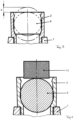
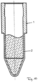
- the Fig.1 shows a sample container 1 according to the invention in a first embodiment.
- the sample container 1 has a housing 2 which is designed with a largely cylindrical outer surface in a first (head section 3) and a second (middle section 4) section.
- the outer surface has only a slight conical taper, which serves to make it easier to demold the plastic housing 2 after injection molding.
- At the end of the middle section 4 opposite the head section 3 there is an end section 5 in which the housing 2 tapers and is thus tapered in a broader sense.
- the housing 2 is made of an (optically) transparent material which enables the use of optical measuring elements in the context of a biotechnological process, such as a PCR process, in which the sample container 1 is to be used.
- the housing 2 On the outside between the head section 3 and the middle section 4, the housing 2 forms a shoulder 6 which serves as a support surface via which the housing 2 can be attached to a sample container carrier 7 (cf. Fig.2 ) is supported.
- a sample chamber is formed within the middle section 4 and the end section 5 of the housing 2, the wall thickness of the housing 2 being largely constant in these two sections, so that a largely cylindrical sample chamber section is formed within the middle section 4 and a conically tapered sample chamber section with a rounded tip is formed in the end section 5 of the housing 2.
- An opening channel is formed in the head section 3 of the housing 2, which makes it possible to fill the sample container 1 with the sample to be examined.
- the sample space is closed by inserting a spherical closure element 8.
- the closure effect ie both the sealing and the fixing of the closure element 8 in the opening channel, is brought about by the largest outer diameter of the closure element 8 being slightly larger than the opening channel in a defined section (closure section 11) (cf. Fig.2 ) and the closure element 8 is thus clamped in the opening channel.
- the opening channel is initially provided with an inlet bevel 9, which defines a relatively large opening cross-section (largest diameter: 4.5 mm) (in relation to the outer diameter of the closure element 8).
- the inlet bevel 9 makes it easier to position the closure element 8 centrally (largest diameter: 4.1 mm to 4.2 mm).
- the inlet bevel 9 merges into a first annular projection 10, which reduces the opening cross-section (diameter: 3.7 mm) of the opening channel in relation to the opening cross-section in the closure section of the opening channel (diameter: approx. 4.0 mm).
- a force component
- the force is so high that it causes a deformation of both the housing 2 in the area of the head section 3 and the closure element 8 itself, which allows the closure element 8 to pass the first projection 10 and be pushed into the closure section 11 of the opening channel.
- the closure element 8 is fixed, i.e. clamped, in the closure section 11 by its larger (maximum) diameter compared to the diameter of the opening channel.
- the forces are achieved by a (largely elastic) deformation of the housing 2 in the area of the closure section 11 and the closure element 8.
- the reaction forces that act from the wall of the opening channel onto the ball - and vice versa - have no component in the longitudinal axial direction of the housing.
- the closure element 8 is held securely after being introduced into the closure section 11, provided that no significant external forces act on it in the longitudinal axial direction of the housing 2.
- the first projection 10, which must be passed by the closure element 8 when it is introduced into the closure section 11, serves on the one hand as an end stop which prevents the closure element 8 from being pushed out of the opening channel when excess pressure develops within the closed sample space, for example due to heating during a biotechnological process, such as a PCR process, and the sample container 1 thus opens unintentionally.
- this projection 10 serves to generate a characteristic force curve when inserting the closure element 8, by means of which an actual insertion of the closure element 8 into the closure section 11 can be detected (in the manner of a snap-in).
- the transition of the opening channel into the sample chamber of the housing 2 is designed as an annular shoulder.
- This shoulder represents a second projection 12, which serves as an end stop for the closure element 8 and thus limits the closure section 11 of the opening channel on the side of the sample chamber.
- the length of the closure section 11 of the opening channel is dimensioned such that the closure element 8 can be displaced over a certain distance x therein before it strikes one of the two projections 11, 12 (cf. Fig.3 ). In the present case, this distance is limited to a maximum of 0.7 mm, since experience has shown that with such a displacement of the closure element 8, the process parameters (in particular pressure, temperature) within the sample space change so little that no significant (negative) effects on the biotechnological process, such as the PCR process, are to be feared.
- This positioning tolerance of the closure element 8 within the closure section 11 also has the advantage that relatively large tolerances can be specified when manufacturing the housing 2 and the closure element 8, which means that lower demands can be placed on the corresponding tools.
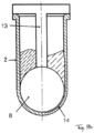
- the Figures 4 to 6 show the use of a plunger 13 (in two embodiments) to push the closure element 8 into the opening channel.
- the plunger 13 has an outer diameter of 3.6 mm (or smaller), which is thus smaller than the inner diameter of the opening channel in the area of the first projection 11.
- the plunger 13 can thus be immersed in the opening channel.
- the movement of the plunger should be precisely controllable in order to prevent it from pressing the closure element 8 against the second projection serving as an end stop with a force that could lead to damage to the housing 2 or the closure element 8.
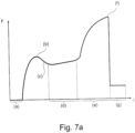
- the Figure 7a shows an example force curve (force F over the plunger path I) for a closing process using a plunger according to Fig.4 .
- force F force over the plunger path I
- a first section (a) of the force curve the force is almost zero; this section defines the displacement of the plunger 13 until it comes into contact with the closure element 8.
- This is followed in a second section by a sharp increase in the force up to a first maximum value (b) (first extreme point of the curves) which is required to allow the closure element to pass the first projection 10.
- This force drops down to a second extreme point (c) which defines the force (which then only increases slightly due to the slightly conical design of the opening channel, see section (d)) which is required to displace the ball in the closure section 11.
- This force corresponds essentially to the force which results from the friction between the wall of the opening channel in the closure section 11 and the section of the closure element 8 which is in contact with it. If the closure process is carried out correctly, the application of force ends somewhere in section (d) of the Fig.7 .
- the Fig. 7b shows a corresponding exemplary force curve for the use of a ram according to the Fig. 5 and 6 .
- the force curve in sections (a) and (d) and in between corresponds to that of the Fig. 7a .
- section (d) there is then a force increase (h), which is even stronger than in the course according to the Fig. 7a This is caused by the impact of the plunger 13 on the edge of the sample container 1.
- the plunger 13 should then only be moved a relatively small distance further in order to avoid overloading the sample container 1 (or the To control the stroke of the ram, the force curve can be evaluated so that, for example, when the end of section (h) is reached, a (force) limit value is reached, which can, for example, lead to a ram drive being switched off.
- a (force) limit value is reached, which can, for example, lead to a ram drive being switched off.
- the further force progression is also shown in dashed lines, which leads to a break in the sample container due to overloading. This is marked by a continuation of section (h) (section (i)), at the end of which the break occurs. This is marked by a direct drop in the force to a level close to zero (section (k)).
- the Fig. 20a to 20f show examples of deviations from the previously described "normal" force curves. From these deviations, the corresponding source of error can be deduced.
- the deviating force curve is shown with a solid line, while the "normal" force curve is shown with a dashed line.
- the Fig. 20a shows two different force curves where the dimensions or the material properties of the sample container in the area of the opening channel and/or the closure element are not correct.
- Fig. 20b shows two different force curves where the vertical alignment of the locking element, ie the distance between the locking element and the plunger, is too small or too large. In the case of the different force curve according to the Fig.
- the horizontal alignment is not correct, ie there is insufficient alignment of the longitudinal axes of the sample container and the plunger. This can lead to an obstruction of the movement of the closure element.
- the Fig. 20d shows a different force curve, which occurs when the closure element is missing and the movement of the plunger takes place without significant force until a collision with the sample container.
- the Fig. 20e The deviating force curve shown may occur if the contact surfaces of the closure element and/or the sample container do not meet the requirements.
- Fig. 20f shows, however, a different force curve that can result from the breakage of a sample container.
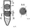
- the Fig. 8a and 8b show a second embodiment of a sample container 1, in which two closure elements 8 are fixed in a force-fitting manner in a common closure section 11 of the housing 2. This creates a second sample space between the two closure elements 8.
- the corresponding design of the opening channel can - unlike the representation in the Fig.8 - any according to the embodiment according to the Figures 1 to 3 , ie in particular be provided with one or more projections.
- a bypass channel 14 is also introduced into the wall of the housing.
- the upper bypass channel 14 serves to prevent excess pressure in the two sample chambers
- the lower bypass channel 14 is intended, however, to transfer a sample contained in the upper sample chamber into the lower sample chamber, for example as part of the PCR process, as is shown in the Fig. 8a is shown.
- the lower closure element 8 is pushed by means of the upper closure element 8 into the section of the opening channel/sample chamber having the lower bypass channel 14, so that the sample can flow from the upper sample chamber via the lower bypass channel 14 past the lower closure element 8 into the lower sample chamber.
- Fig. 9a to 9b show a sample container 1 in a further embodiment, in which it is intended to be opened again by the closure element 8 being pushed completely into the sample chamber up to the closed end by means of a plunger 13.
- the sample liquid displaced in this way can flow out via a bypass channel 14 introduced into the wall of the housing 2 on one side and thus be removed from the sample container 1.
- the Fig.10 shows a sample container 1 in which the housing 2 is provided with a varying wall thickness in the area of the sample chamber.
- the housing 2 In the area of the sample chamber that holds the sample, the housing 2 has the smallest possible wall thickness of e.g. 0.2 to 0.3 mm.
- a small wall thickness simplifies the examination of the sample using optical methods.
- the wall thickness In a section of the sample chamber that forms a dead space (ie without a sample contained therein), the wall thickness is, however, thicker (e.g. twice as thick, e.g. 0.4 to 0.6 mm), which not only increases the mechanical stability of the housing 2, but also reduces evaporation of the sample through the housing 2.
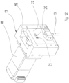
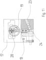
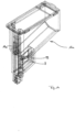
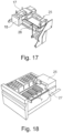
- FIGS 11 and 12 show individual components of an automated closing device (cf. Figure 17 ) which are to be used in a device for carrying out a PCR process (cf. Figure 18 ).
- the Figure 11 a storage container 15 in which an elongated spiral guide 16 is arranged, which serves to receive and guide a plurality of closure elements 13 of a sample container 1.
- the lower end of the guide 16 ends in an outlet opening, via which the closure elements of a closure unit 17, as partially shown in the Figure 12 shown.
- the storage container 15, which can be sold as a filled disposable container, can be attached to the front end of the closing unit 17 for this purpose.
- the closing unit 17 comprises an electric motor arranged in a housing 18, via which a drive disk 19 can be driven in rotation.
- the drive disk 19 is provided with a bolt 20 in a decentralized manner, which is guided in an elongated hole 21 of a tappet guide 22.
- the guidance of the bolt 20 in the elongated hole 21 translates the rotary movement of the drive disk 19 into a cyclical upward and downward movement of the tappet guide 22 including a tappet 13 attached to it, as is basically the case in the Figure 13 is shown.
- a closure element 8 held in a transfer position is taken along and is guided via an outlet opening of the closure unit into the opening channel of a housing 2 of a sample container 1 arranged underneath (in the Fig. 13 not shown).
- This embodiment can also be further developed in such a way that the cyclical movement of the plunger 13 is basically realized by a continuous rotation of the drive disk 19 and the drive motor only stops the movement and reverses its direction of movement when there is a risk of exceeding the permissible force.
- the Fig. 14 shows a storage container 15a for a plurality of closure elements 8 in an alternative embodiment.
- the essential differences to the storage container 15 according to the Fig. 11 are that, on the one hand, the closure elements 8 are stored unsorted in a storage space of the storage container 15a, ie as a bulk material, and, on the other hand, a plunger 13a is integrated for the individual dispensing of the closure elements 8 from the storage container 15a.
- the bottom and wall surfaces of the storage container 15a are designed in such a way that the closure elements located at the bottom in the bulk material are fed to a dispensing channel 29, the inner diameter of which is only slightly larger than the outer diameter of the closure elements. This ensures that the closure elements are individually moved into a transfer position where they can be grasped and taken away by the plunger 13a.
- the Fig. 15 shows the use of the storage container according to the Fig. 14 in combination with an alternative closing unit 17a (only partially shown).
- a special feature of this combination is the use of a total of two plungers, firstly the plunger 13a integrated in the storage container 15a, which serves to individually dispense the closure elements 8 from the storage container, whereby these are placed on a sample container 1 located underneath.
- a second plunger 13 integrated in the closing unit 17a serves to drive the closure element 8 previously placed on a (different) sample container 1 into the closure section of the opening channel of this sample container.
- the main advantage of using two plungers is improved hygiene when the storage container 17a including the plunger 13a is used as a disposable container, which is thus disposed of after use.
- the movements of the two tappets 13, 13a are coupled to one another.
- the movement of the tappet 13 is thus transferred to the tappet 13a.
- the tappet 13 itself is constructed in several parts and comprises a tappet element 31, which is axially displaceably mounted in the lower end of a base body 32 of the tappet 13.
- the tappet element 31 is connected to a threaded pin 33, which is part of a force limiting unit, via a central bore with an internal thread.
- the force limiting unit also comprises a spring 34 (cylindrical coil spring), which is preloaded by two contact plates 35.
- the preload forces are supported by the upper support plate 35 and an annular projection of the tappet element 31 on corresponding contact surfaces of the base body 32.
- the preload of the coil spring can be changed by the depth of screwing the threaded bolt 33 into the tappet element 31 and thus a limit value for the force exerted by the tappet element 31 on the closure element 8 can be set. As soon as this force is exceeded, the tappet stroke is (partially) compensated by the tappet element 13 moving back.
- the Fig. 16 shows a closing unit 17b, which is functionally essentially the same as that of the Fig. 15 corresponds, but is structurally simpler.
- a (mechanical) force limiting unit is not provided there, rather this is achieved electronically, by a corresponding control of a tappet drive.
- the tappet element 31a is therefore axially immovably integrated in the base body 32a of the tappet 13 and also the bolt 30a for driving the tappet 13a of the
- the storage container 15a is not spring-mounted.
- the storage container 15a corresponds to that of the Fig. 15 .
- the closing units 17, 17a, 17b and storage containers 15, 15a can be integrated into an automatic closing device 25 as shown in the Figure 17 is shown. There, the unit comprising the closing unit 17 and the storage container 15 can be moved along a first axis (in the transverse direction) via a linear drive 26.
- the automatic closing device according to the Figure 17 is in turn integrated into a device for carrying out a PCR process according to Figure 18 integrated in such a way that the entire closing device 25 can be moved via a second linear drive 27 to a second axis (in the longitudinal direction) which is aligned perpendicular to the first axis (the travel axis of the linear drive 26 of the closing device).
- the ability of the unit comprising the closing unit 17 and the storage container 15 to move in two axes aligned perpendicular to one another makes it possible to move a large number of housings 2 of sample containers 1, which are positioned in several rows in a total of three sample container carriers 7, and to close each one with a closure element 8.
- the correct placement of the closure element 8 in the individual housings 2 is checked with the aid of a laser distance sensor (not shown).
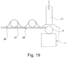
- the Fig. 19 shows in a schematic representation the possibility of releasably fixing the closure elements 8 in a conveyor belt (blister belt) 28 and of positioning them one after the other in the transfer position by moving the conveyor belt 28, from which they can then be introduced into the opening channel of a sample container 1 by means of a plunger 13.
- the conveyor belt 28 has a base belt 36 provided with openings arranged at regular intervals, wherein in the area of each of the openings a closure element 8 rests on one side of the base belt 26 and is surrounded there by a holding band 37 and thus held.
- the individual closure elements can be released from the conveyor belt 28 through the respective opening by means of the plunger 13 and driven into the opening channel of the sample container 1.
Description
Die Erfindung betrifft ein Probenbehältnis mit einem Gehäuse, das einen Probenraum zur Aufnahme einer Probe ausbildet und zumindest eine kreisförmige Öffnung aufweist, sowie mit einem kugelförmigen Verschlusselement.The invention relates to a sample container with a housing which forms a sample space for receiving a sample and has at least one circular opening, as well as with a spherical closure element.
Derartige Probenbehältnisse finden insbesondere im Rahmen von biotechnologischen Verfahren Anwendung, um eine biologische Probe bzw. eine biologisches Material wie bspw. Nukleinsäuren enthaltende Probe zu prozessieren. Sie werden beispielsweise dazu benutzt, im Rahmen von Amplifikationsreaktionen wie bspw. einer Polymerase-Kettenreaktion ("Polymerase Chain Reaction", PCR) Nukleinsäuren in vitro zu vervielfältigen. Die Probenbehältnisse dienen dabei der Aufnahme der die Nukleinsäure umfassenden Probe.Such sample containers are used in particular in biotechnological processes to process a biological sample or a sample containing biological material such as nucleic acids. They are used, for example, to replicate nucleic acids in vitro in amplification reactions such as a polymerase chain reaction (PCR). The sample containers serve to hold the sample containing the nucleic acid.
Aus dem Stand der Technik sind eine Vielzahl unterschiedlicher Probenbehältnisse bekannt, die im Rahmen von entsprechenden biotechnologischen Verfahren wie bspw. der PCR regelmäßig als Einwegprodukte verwendet werden. Die Probenbehältnisse werden dabei zunächst mit der Probe befüllt, dann luftdicht verschlossen und schließlich dem PCR-Prozess zugeführt. An das Verschließen der Probenbehältnisse werden dabei hohe Anforderungen gestellt. Zum einen müssen die Probenbehältnisse zuverlässig dicht verschlossen werden, um das Ergebnis des PCR-Prozesses nicht durch den ungewollten Ein- oder Austritt von Probenmaterial zu beeinträchtigen. Zum anderen werden im Rahmen eines PCR-Prozesses regelmäßig eine Vielzahl von Probenbehältnissen verwendet, die hierzu befüllt und verschlossen werden müssen. Dies sollte daher möglichst automatisiert erfolgen. Weiterhin müssen die Probenbehältnisse kostengünstig herstellbar sein, insbesondere weil sie in großer Anzahl benötigt werden und als Einwegprodukte zum Einsatz kommen.A large number of different sample containers are known from the state of the art and are regularly used as disposable products in corresponding biotechnological processes such as PCR. The sample containers are first filled with the sample, then sealed hermetically and finally fed into the PCR process. High demands are placed on the sealing of the sample containers. On the one hand, the sample containers must be reliably sealed so that the result of the PCR process is not affected by the unwanted entry or exit of sample material. On the other hand, a large number of sample containers are regularly used in a PCR process and must be filled and sealed for this purpose. This should therefore be done as automatically as possible. Furthermore, the sample containers must be cost-effective to produce, particularly because they are required in large numbers and are used as disposable products.
Aus der
Das aus der
Der Erfindung lag die Aufgabe zugrunde, ein verbessertes Probenbehältnis anzugeben. Insbesondere sollte das erfindungsgemäße Probenbehältnis kostengünstig herstellbar und unter relativ geringem Aufwand automatisiert verschließbar sein. Gleichzeitig sollte das erfindungsgemäße Probenbehältnis eine zuverlässige Dichtwirkung haben.The invention was based on the object of specifying an improved sample container. In particular, the sample container according to the invention should be inexpensive to manufacture and be able to be closed automatically with relatively little effort. At the same time, the sample container according to the invention should have a reliable sealing effect.
Diese Aufgabe wird durch ein Probenbehältnis gemäß dem unabhängigen Patentanspruch 1 gelöst. Vorteilhafte Weiterbildungen sind Gegenstand der abhängigen Patentansprüche und ergeben sich aus der nachfolgenden Beschreibung der Erfindung.This object is achieved by a sample container according to
Der Kern der Erfindung liegt darin, die bei dem Probenbehältnis gemäß der
Ein Probenbehältnis gemäß Anspruch 1 wird geschaffen. Das Probenbehältnis weist ein Gehäuse auf, das einen Probenraum zur Aufnahme einer Probe und eine kreisförmige Öffnung ausbildet, die sich kanalförmig in den Probenraum erstreckt. Weiterhin weist das erfindungsgemäße Probenbehältnis ein kugelförmiges Verschlusselement auf. Der (größte) Durchmesser des Verschlusselements ist so gewählt, dass dieser den Durchmesser des Öffnungskanals in zumindest einem (Verschluss-)Abschnitt des Öffnungskanals übersteigt, jedoch nur mit einem Maß, das es erlaubt, das Verschlusselement so weit in den Verschlussabschnitt des Öffnungskanals einzubringen, dass die kraftschlüssige Fixierung durch einen Kontakt eines den größten Umfang des Verschlusselements umfassenden Bereichs mit dem Verschlussabschnitt erreicht wird. Das kugelförmige Verschlusselement ist in Kontakt mit dem Gehäuse. Ferner bildet der Öffnungskanal zwischen dem Verschlussabschnitt und der innenseitigen Öffnung einen (ersten) Vorsprung aus, der den Öffnungsquerschnitt des Öffnungskanals gegenüber dem Öffnungsquerschnitt im Verschlussabschnitt verkleinert. Durch den direkten Kontakt des Verschlusselements mit dem Gehäuse ist ein einteiliger Verschluss ausgebildet. Durch die Ausbildung eines einteiligen Verschlusselements und die Ausgestaltung des Öffnungskanals mit dem (ersten) Vorsprung kann eine kostengünstige Herstellung des Probenbehältnisses mit Verschlusselement erreicht werden, das mit relativ geringem Aufwand automatisiert verschließbar ist, wobei eine zuverlässige Dichtwirkung vorliegt. Der (erste) Vorsprung kann als Endanschlag dienen, der verhindert, dass das Verschlusselement beim Einbringen über den Verschlussabschnitt hinaus in den Probenraum gedrückt wird.A sample container according to
Die kraftschlüssige Fixierung des Verschlusselements durch einen Kontakt eines den größten Umfang des kugelförmigen Verschlusselements umfassenden Bereichs mit der Wand des Öffnungskanals ist wichtig, um einen sichere Fixierung zu erreichen. Die resultierenden Kräfte bei dieser Art der kraftschlüssigen Fixierung weisen nämlich keine oder nur eine verhältnismäßig kleine (und damit vernachlässigbare) Kraftkomponente in längsaxialer Richtung des Öffnungskanals auf; vielmehr sind diese (weitgehend) radial in Richtung des Zentrums des kugelförmigen Verschlusselements gerichtet. Dadurch kann mit einer nur relativ kleinen (vorzugsweise elastischen) Deformation des Verschlusselements und der Wand des Öffnungskanals eine ausreichende Fixierung und gleichzeitig eine gute Dichtwirkung erzeugt werden. Eine geringe Deformation erfordert dann auch nur relativ geringe Kräfte zum Einbringen des Verschlusselements in den Öffnungskanal. Dies kann die Automatisierung des Verschließens des Probenbehältnisses vereinfachen und auch ein manuelles Verschließen des Probenbehältnisses ermöglichen. Zudem werden die Anforderungen an die für das Verschlusselement und das Gehäuse verwendeten Werkstoffe reduziert, wodurch die Herstellungskosten für das Probenbehältnis gering gehalten werden können.The force-fitting fixation of the closure element by contact of an area comprising the largest circumference of the spherical closure element with the wall of the opening channel is important in order to achieve a secure fixation. The resulting forces in this type of force-fitting fixation have no or only a relatively small (and thus negligible) force component in the longitudinal axial direction of the opening channel; rather, they are directed (largely) radially towards the center of the spherical closure element. As a result, sufficient fixation and at the same time a good sealing effect can be achieved with only a relatively small (preferably elastic) deformation of the closure element and the wall of the opening channel. A small deformation then requires only relatively small forces to introduce the closure element into the opening channel. This can simplify the automation of closing the sample container and also enable manual closing of the sample container. In addition, the requirements for the materials used for the closure element and the housing are reduced, which keeps the manufacturing costs for the sample container low.
Bei dem Probenbehältnis der
Die Wahl der Werkstoffe sowie der Abmessungen des Verschlusselements und des Gehäuses im Bereich des Verschlussabschnitts kann gezielt hinsichtlich des gewünschten Deformationsverhaltens erfolgen. Eine im Vergleich zum dem Gehäuse weiche Kugel (die sich somit deutlich mehr verformt als das Gehäuse) kann Vorteile bei der Dichtwirkung haben. Diesem Vorteil stehen jedoch gegebenenfalls Nachteile bei der Positionierung(süberprüfung) und der Werkstoffauswahl gegenüber. Eine im Vergleich zum Gehäuse harte Kugel lässt sich dagegen gut beim Einbringen handhaben und ermöglicht eine einfachere Positionierung und Positionsüberprüfung, kann jedoch das Risiko einer Überdehnung des Gehäuses (bis in den plastischen Bereich hinein) mit sich bringen.The choice of materials and dimensions of the closure element and the housing in the area of the closure section can be made specifically with regard to the desired deformation behavior. A ball that is softer than the housing (which therefore deforms significantly more than the housing) can have advantages in terms of sealing. However, this advantage may be offset by disadvantages in terms of positioning (checking) and material selection. A ball that is harder than the housing, on the other hand, is easier to handle during insertion and enables easier positioning and position checking, but can bring with it the risk of overstretching the housing (up to the plastic range).
In einer bevorzugten Ausführungsform des erfindungsgemäßen Probenbehältnisses kann vorgesehen sein, dass der Öffnungskanal zwischen dem Verschlussabschnitt und der außenseitigen Öffnung einen (zweiten bzw. weiteren) Vorsprung ausbildet, der den Öffnungsquerschnitt des Öffnungskanals gegenüber dem Öffnungsquerschnitt in dem Verschlussabschnitt verkleinert. Ein solcher Vorsprung, der beispielsweise (geschlossen) ringförmig oder auch durch einen oder mehrere, vorzugsweise ringförmig nebeneinander angeordnete Einzelvorsprünge ausgebildet werden kann, kann insbesondere dazu dienen, als Sicherungsanschlag ein ungewolltes Lösen des Verschlusselements aus dem Verschlussabschnitt des Öffnungskanals, beispielsweise in Folge einer unerwartet hohen Druckerhöhung in dem Probenraum, die beispielsweise durch ein Erwärmen im Rahmen des PCR-Prozesses begründet sein kann, zu verhindern. Sollte die Druckerhöhung innerhalb des Probenraums so groß werden, dass die kraftschlüssige Verbindung des in dem Verschlussabschnitt gehaltenen Verschlusselements überwunden wird, so kann sich das Verschlusselement - gegebenenfalls nach einer geringfügigen Verschiebung innerhalb des Verschlussabschnitts des Öffnungskanals - an dem Vorsprung abstützen, wodurch weiterhin ein sicheres und insbesondere dichtes Verschließen des Probenbehältnisses erreicht werden kann.In a preferred embodiment of the sample container according to the invention, it can be provided that the opening channel between the closure section and the outside opening forms a (second or further) projection, which reduces the opening cross-section of the opening channel compared to the opening cross-section in the closure section. Such a projection, which can be formed, for example, in a (closed) ring shape or by one or more individual projections arranged next to one another, preferably in a ring shape, can be used in particular as a safety stop to prevent the closure element from accidentally coming loose from the closure section of the opening channel, for example as a result of an unexpectedly high pressure increase in the sample chamber, which can be caused, for example, by heating during the PCR process. If the pressure increase within the sample chamber becomes so great that the force-fit connection of the closure element held in the closure section is overcome, the closure element can - possibly after a slight displacement within the closure section of the opening channel - support itself on the projection, whereby a secure and, in particular, tight closure of the sample container can still be achieved.
Da der (zweite bzw. weitere) Vorsprung beim Verschließen des Probenbehältnisses von dem Verschlusselement passiert werden muss, kann vorgesehen sein, diesen so zu dimensionieren, dass das Einbringen des Verschlusselements in den Verschlussabschnitt unter Ausübung einer definierten Einpresskraft erfolgt, die nicht so hoch bemessen sein sollte, dass dies zu einer Beschädigung des Verschlusselements oder des Gehäuses des Probenbehältnisses in Folge einer zu großen Deformation kommt, jedoch größer als die maximal zu erwartende, in einer Druckerhöhung im Probenraum begründete Kraft.Since the (second or further) projection must be passed by the closure element when closing the sample container, it can be designed in such a way that the closure element is inserted into the closure section by exerting a defined pressing force, which should not be so high that it causes damage to the closure element or the housing of the sample container as a result of excessive deformation, but greater than the maximum force to be expected due to an increase in pressure in the sample chamber.
Es ist vorzugsweise auch vorgesehen, dass der Öffnungsquerschnitt des Öffnungskanals im Bereich des (zweiten) Vorsprungs größer als im Bereich des ersten Vorsprungs ist. Dadurch kann erreicht werden, dass die Kraft, die zum Einpressen des Verschlusselements in den Öffnungskanal aufgebracht wird, ausreichend hoch ist, dass das Verschlusselement den zweiten Vorsprung passiert, jedoch nicht so hoch ist, dass dieses auch den ersten Vorsprung passieren kann.It is also preferably provided that the opening cross-section of the opening channel is larger in the region of the (second) projection than in the region of the first projection. This makes it possible to ensure that the force applied to press the closure element into the opening channel is sufficiently high for the closure element to pass the second projection, but not so high that it can also pass the first projection.
In einer weiterhin bevorzugten Ausführungsform des erfindungsgemäßen Probenbehältnisses kann zudem vorgesehen sein, dass die Distanz zwischen dem ersten und dem zweiten Verschlusselement in Abhängigkeit von den Abmessungen des Verschlusselements so bemessen wird, dass eine Positionierungstoleranz des Verschlusselements innerhalb des Verschlussabschnitts von maximal 5 mm und insbesondere von maximal 0,7 mm gegeben ist. Dies bedeutet, dass das Verschlusselement lediglich über diese Distanz zwischen den beiden Vorsprüngen verschiebbar ist. Eine Verschiebung des Verschlusselements über diese Maximaldistanz, insbesondere aufgrund einer Druckerhöhung innerhalb des Probenraums, führt in der Regel noch zu einer tolerierbaren Veränderung der Prozessbedingungen bspw. eines PCR-Prozesses. Gleichzeitig kann vermieden werden, dass eine höhere Toleranz zur Fertigung des Probenbehältnisses eingehalten werden muss, die diese verteuern könnte.In a further preferred embodiment of the sample container according to the invention, it can also be provided that the distance between the first and the second closure element is dimensioned depending on the dimensions of the closure element such that a positioning tolerance of the closure element within the closure section of a maximum of 5 mm and in particular a maximum of 0.7 mm is given. This means that the closure element can only be moved over this distance between the two projections. A displacement of the closure element over this maximum distance, in particular due to an increase in pressure within the sample space, usually still leads to a tolerable change in the process conditions, for example of a PCR process. At the same time, it can be avoided that a higher tolerance for the production of the sample container has to be maintained, which could make it more expensive.
Der Öffnungskanal ist im Bereich des Verschlussabschnitts zylindrisch ausgebildet ist. Dadurch wird unabhängig von der tatsächlichen Position des Verschlusselements in dem Verschlussabschnitt stets eine im Wesentlichen gleich hohe kraftschlüssige Fixierung und Dichtwirkung erreicht. Gegebenenfalls kann vorgesehen sein, den Öffnungskanal (auch) im Verschlussabschnitt geringfügig konisch (beispielsweise mit einer Neigungswinkel von 0,1 bis 0,5°) auszubilden, der ein Entformen beim Gießen und insbesondere Spritzgießen des Gehäuses erleichtern kann. Der Neigungswinkel kann so gering gewählt sein, dass dieser keinen wesentlichen (negativen) Einfluss auf die Fixierung und Dichtwirkung des geklemmten Verschlusselements hat.The opening channel is cylindrical in the area of the closure section. This means that a substantially equal level of force-locking fixation and sealing effect is always achieved, regardless of the actual position of the closure element in the closure section. If necessary, the opening channel can be designed to be slightly conical (for example with an angle of inclination of 0.1 to 0.5°) in the closure section as well, which can facilitate demolding during casting and in particular injection molding of the housing. The angle of inclination can be chosen to be so small that it has no significant (negative) influence on the fixation and sealing effect of the clamped closure element.
Das Gehäuse des erfindungsgemäßen Probenbehältnisses kann vorzugsweise (auch abgestuft) rohrförmig ausgebildet sein, wobei die Öffnung an einem (längsaxialen) Ende des Gehäuses angeordnet ist. Weiterhin vorzugsweise kann das Gehäuse an dem zweiten Ende spitz zulaufend ausgebildet sein, wodurch auch sehr geringe Probenmengen gut in dem Probenraum konzentriert werden können, was die Durchführung des biotechnologischen Verfahrens, wie bspw. eines PCR-Prozesses erleichtern kann.The housing of the sample container according to the invention can preferably be tubular (also stepped), with the opening being arranged at one (longitudinal) end of the housing. Furthermore, the housing can preferably be tapered at the second end, whereby even very small sample quantities can be easily concentrated in the sample space, which can facilitate the implementation of the biotechnological process, such as a PCR process.
Um eine Untersuchung der Probe mittels optischer Methoden (auch reine Sichtprüfung) zu ermöglichen, kann weiterhin vorgesehen sein, dass das Gehäuse des Probenbehältnisses zumindest teilweise aus einem optisch transparenten Werkstoff ausgebildet ist. Insbesondere das spitz zulaufende Ende kann dabei optisch transparent ausgebildet sein, da dieses vorzugsweise der Aufnahme der Probe dient.In order to enable the sample to be examined using optical methods (including purely visual inspection), it can also be provided that the housing of the sample container is at least partially made of an optically transparent material. In particular, the tapered end can be optically transparent, as this is preferably used to hold the sample.
Weiterhin vorzugsweise kann vorgesehen sein, das Gehäuse in dem Bereich, das der Aufnahme der Probe dient, mit einer geringeren Wandstärke auszuführen als (zumindest) einen zweiten Bereich des den Probenraum bildenden Gehäuses. Eine möglichst dünne Wandstärke kann die Untersuchung der Probe mittels optischer Methoden vereinfachen, während eine dickere Wandstärke, insbesondere in einem Totraum des Probenraums, der nicht mit der Probe befüllt ist, eine Evaporation durch das vorzugsweise aus Kunststoff gefertigte Gehäuse vermeiden oder vermindern kann.Furthermore, it can preferably be provided that the housing in the area that serves to hold the sample has a thinner wall thickness than (at least) a second area of the housing that forms the sample chamber. A wall thickness that is as thin as possible can simplify the examination of the sample using optical methods, while a thicker wall thickness, in particular in a dead space in the sample chamber that is not filled with the sample, can prevent or reduce evaporation through the housing, which is preferably made of plastic.
Weiterhin kann auch vorgesehen sein, das Gehäuse in dem Verschlussabschnitt des Öffnungskanals aus einem (optisch) transparenten Werkstoff auszubilden. Dies ermöglicht die Überprüfung der Position des Verschlusselements in dem Verschlussabschnitt und zudem der Dichtwirkung mittels optischer Mittel (auch reine Sichtprüfung). Für eine maschinelle Überprüfung kann beispielsweise eine Veränderung des Brechungsindexes genutzt werden, die darin begründet ist, dass sich bei dem Übergang von einem ersten Feststoff (Wand des Öffnungskanals) zu einem zweiten Feststoff (Verschlusselement) keine Totalreflexion des Lichts an der Innenwand einstellt, beim Übergang von einem Feststoff (Wand des Öffnungskanals) zu Luft die Innenseite des Öffnungskanals dagegen teilweise spiegelt.Furthermore, it can also be provided that the housing in the closure section of the opening channel is made of an (optically) transparent material. This enables the position of the closure element in the closure section and also the sealing effect to be checked by optical means (also purely visual inspection). For a mechanical inspection, for example, a change in the refractive index can be used, which is based on the fact that there is no total reflection of the light at the transition from a first solid (wall of the opening channel) to a second solid (closure element). inner wall, whereas when a solid (wall of the opening channel) changes to air, the inside of the opening channel partially reflects.
Weiterhin bevorzugt kann das Gehäuse einen Absatz zur Ausbildung einer Auflagefläche ausbilden. Über diese Auflagefläche können die Kräfte, die zum Einpressen des Verschlusselements aufgebracht werden (typischerweise bis 60 N bis 130 N und maximal 250 N), an einer das Probenbehältnis tragenden Halterung abgestützt werden. Insbesondere kann die Auflagefläche an einer Stelle des Gehäuses ausgebildet sein, die sich in der Nähe des Verschlussabschnitts des Öffnungskanals befindet. Dadurch kann vermieden werden, dass die Kräfte über andere Abschnitte des Gehäuses, die gegebenenfalls mit geringeren Wandstärken und somit empfindlicher ausgebildet sind (insbesondere die den Probenraum umgebende Wand des Gehäuses), übertragen werden.Furthermore, the housing can preferably form a shoulder to form a support surface. The forces that are applied to press in the closure element (typically up to 60 N to 130 N and a maximum of 250 N) can be supported on a holder that supports the sample container via this support surface. In particular, the support surface can be formed at a point on the housing that is located near the closure section of the opening channel. This can prevent the forces from being transmitted via other sections of the housing, which may have thinner walls and are therefore more sensitive (in particular the wall of the housing surrounding the sample space).
Weiterhin ist das Gehäuse des Probenbehältnisses zumindest in dem Verschlussabschnitt des Öffnungskanals und das Verschlusselement selbst aus einem Werkstoff mit einem gleich großen Ausdehnungskoeffizienten ausgebildet. Dadurch kann vermieden werden, dass sich die Pressung in der Kontaktfläche zwischen dem Verschlusselement und der Wand des Öffnungskanals in Folge einer beispielsweise während eines PCR-Prozesses erfolgten Erwärmung verändert, wodurch gegebenenfalls im gleichen Maße nicht nur die Fixierung des Verschlusselements sondern auch dessen Dichtwirkung verändert würde.Furthermore, the housing of the sample container, at least in the closure section of the opening channel, and the closure element itself are made of a material with an equally large coefficient of expansion. This prevents the pressure in the contact surface between the closure element and the wall of the opening channel from changing as a result of heating, for example during a PCR process, which could potentially change not only the fixation of the closure element but also its sealing effect to the same extent.
In einer bevorzugten Ausführungsform des erfindungsgemäßen Probenbehältnisses kann das Verschlusselement aus einem elektrisch leitfähigen Werkstoff ausgebildet sein. Dadurch kann nicht nur eine elektrostatische Aufladung der Kugel vermieden werden, die die Handhabung des Probenbehältnisses erschweren könnte, sondern die Leitfähigkeit kann zudem erlauben, eine kontaktgebundene oder auch kontaktlose, beispielsweise kapazitive oder induktive Detektion der Position des Verschlusselements innerhalb des Öffnungskanals und/oder der Dichtwirkungen durchzuführen.In a preferred embodiment of the sample container according to the invention, the closure element can be made of an electrically conductive material. This not only prevents electrostatic charging of the ball, which could make handling the sample container more difficult, but the conductivity can also allow contact-based or contactless, for example capacitive or inductive, detection of the position of the closure element within the opening channel and/or the sealing effects.
Vorzugsweise ist das Verschlusselement des erfindungsgemäßen Probenbehältnisses aus einem Werkstoff ausgebildet, der keine Eigenfluoreszenz aufweist. Dadurch kann vermieden werden, dass eine auf der Messung der Fluoreszenz der Probe beruhende Überwachung des biotechnologischen Verfahrens, wie bspw. des PCR-Prozesses negativ beeinträchtigt wird.Preferably, the closure element of the sample container according to the invention is made of a material that does not exhibit any inherent fluorescence. This can prevent a negative impact on monitoring of the biotechnological process, such as the PCR process, based on measuring the fluorescence of the sample.
Um ein einfaches Öffnen des Probenbehältnisses nach der Verwendung zu ermöglichen, kann dieses mit einer Sollbruchstelle versehen sein, an der das Gehäuse durch eine definierte Krafteinwirkung zerteilt wird. Eine solche Art der Öffnung eignet sich insbesondere für solche Probenbehältnisse, die lediglich einmal verwendet werden sollen (Einweg-Probenbehältnis). Ein Vorteil dieser Ausgestaltung des erfindungsgemäßen Probenbehältnisses kann insbesondere darin liegen, dass der Prozess des Öffnens weniger aufwendig sein kann, als ein Entfernen des in dem Verschlussabschnitt des Öffnungskanals fixierten Verschlusselements, was jedoch ebenfalls möglich ist. Anstelle einer Sollbruchstelle besteht auch die Möglichkeit, das Gehäuse zweiteilig auszubilden, wobei die beiden Teile beispielsweise über eine Steck- oder Rastverbindung miteinander verbindbar sind. Zum Öffnen des verschlossenen Probenbehältnisses kann das Gehäuse an dieser Verbindungsstelle dann wieder geöffnet werden.To enable easy opening of the sample container after use, it can be provided with a predetermined breaking point at which the housing is split by a defined force. This type of opening is suitable particularly for sample containers that are only to be used once (disposable sample container). One advantage of this design of the sample container according to the invention can be that the process of opening it can be less complicated than removing the closure element fixed in the closure section of the opening channel, which is also possible. Instead of a predetermined breaking point, it is also possible to design the housing in two parts, with the two parts being connectable to one another, for example, via a plug or snap connection. To open the closed sample container, the housing can then be opened again at this connection point.
Das Probenbehältnis kann auch geöffnet werden, indem das Verschlusselement in den Probenraum gestoßen wird. Der Probenraum sollte hierzu zumindest in einem Abschnitt eine größere Querschnittsfläche als das Verschlusselement aufweisen, um den Probenraum leeren zu können.The sample container can also be opened by pushing the closure element into the sample chamber. The sample chamber should have a larger cross-sectional area than the closure element in at least one section in order to be able to empty the sample chamber.
Bei einigen Anwendungen sollen Probenbehältnisse, die im Rahmen des jeweiligen biotechnologischen Verfahrens (wie bspw. eines PCR-Prozesses) eingesetzt werden, nicht wieder geöffnet werden. Um einen dauerhaften Verschluss des erfindungsgemäßen Probenbehältnisses sicherzustellen, kann erfindungsgemäß weiterhin vorgesehen sein, das Verschlusselement zusätzlich in dem Verschlussabschnitt zu sichern, beispielsweise indem dieses - bei geeigneter Werkstoffwahl mit der Wand des Gehäuses verschweißt (z.B. durch Ultraschallschweißen oder thermisches Schweißen) oder durch das Umbördeln eines oberen Rands des Gehäuses formschlüssig fixiert wird. Selbstverständlich sind beliebige andere Arten der zusätzlichen form-, kraft- oder stoffschlüssigen Fixierung möglich.In some applications, sample containers that are used as part of the respective biotechnological process (such as a PCR process) should not be opened again. In order to ensure a permanent closure of the sample container according to the invention, the invention can also provide for the closure element to be additionally secured in the closure section, for example by welding it to the wall of the housing (e.g. by ultrasonic welding or thermal welding) with a suitable choice of material or by securing it in a form-fitting manner by flanging an upper edge of the housing. Of course, any other types of additional form-fitting, force-fitting or material-fitting fixation are possible.
In einer bevorzugten Ausführungsform des erfindungsgemäßen Probenbehältnisses kann weiterhin vorgesehen sein, einen zweiten Verschlussabschnitt für ein zweites Verschlusselement vorzusehen, wobei zwischen den zwei Verschlusselementen ein zweiter Probenraum ausgebildet ist. Sämtliche Weiterbildungen, die zuvor bezüglich des ersten Verschlussabschnitts und/oder des ersten Verschlusselements aufgezeigt wurden, können dabei auch für den zweiten Verschlussabschnitt und/oder das zweite Verschlusselement vorgesehen sein.In a preferred embodiment of the sample container according to the invention, it can also be provided to provide a second closure section for a second closure element, with a second sample space being formed between the two closure elements. All further developments that were previously shown with regard to the first closure section and/or the first closure element can also be provided for the second closure section and/or the second closure element.
Vorzugsweise kann zwischen den beiden Verschlussabschnitten des Probenbehältnisses (zumindest) ein Bypasskanal in der Wand des Gehäuses vorgesehen sein. Dieser kann dazu dienen, einen ansonsten in dem unteren Probenraum entstehenden Überdruck infolge des Einbringens des einen Verschlusselements bis in den unteren Verschlussabschnitts zu vermeiden und das obere Probenmaterial in den unteren Probenraum durch ein Herunterdrücken des oberen Verschlusselements zu überführen.Preferably, (at least) one bypass channel can be provided in the wall of the housing between the two closure sections of the sample container. This can serve to avoid an overpressure that would otherwise arise in the lower sample chamber as a result of the introduction of one closure element into the lower closure section and to upper sample material into the lower sample chamber by pressing down the upper closure element.
Es wird ein Verfahren zur Aufbereitung oder Bearbeitung einer biologischen Probe oder einer biologisches Material wie insbesondere Nukleinsäuren enthaltenden Probe beschrieben, bei dem das erfindungsgemäße Probenbehältnis eingesetzt wird. Das erfindungsgemäße Probenbehältnis ist im Detail in der Beschreibung und den Ansprüchen beschrieben. Es wird auf die entsprechende Offenbarung Bezug genommen. Das Verfahren kann insbesondere ein biotechnologisches Verfahren wie bspw. ein Amplifikationsverfahren, insbesondere ein PCR Verfahren, sein.A method for preparing or processing a biological sample or a sample containing biological material such as nucleic acids in particular is described, in which the sample container according to the invention is used. The sample container according to the invention is described in detail in the description and the claims. Reference is made to the corresponding disclosure. The method can in particular be a biotechnological method such as an amplification method, in particular a PCR method.
Die Erfindung wird nachfolgend anhand von in den Zeichnungen dargestellten Ausführungsbeispielen näher erläutert.The invention is explained in more detail below with reference to embodiments shown in the drawings.
In den Zeichnungen zeigt:
- Fig. 1:
- ein Probenbehältnis eines Systems;
- Fig. 2:
- einen Ausschnitt des Probenbehältnisses der
Fig. 1 in einer geschnittenen Seitenansicht; - Fig. 3:
- einen weiteren Ausschnitt des Probenbehältnisses der
Fig. 1 in einer geschnittenen Seitenansicht; - Fig. 4:
- das Einbringen des Verschlusselements in das Probenbehältnis gemäß den
Fig. 1 mittels eines Stößels in einer ersten Ausführungsform;bis 3 - Fig. 5 und 6:
- das Einbringen eines Verschlusselements in ein Probenbehältnis gemäß
Fig. 1 mittels eines Stößels in einer zweiten Ausführungsform; - Fig. 7a:
- den Kraftverlauf beim Einbringen von Verschlusselementen in Probenbehältnisse gemäß den
Fig. 1 unter Verwendung eines Stößels gemäßbis 3Fig. 4 ; - Fig. 7b:
- den Kraftverlauf beim Einbringen von Verschlusselementen in Probenbehältnisse gemäß den
Fig. 1 unter Verwendung eines Stößels gemäß denbis 3Fig. 5 und6; - Fig. 8a und 8b:
- ein Probenbehältnis eines Systems in einer zweiten Ausführungsform in zwei unterschiedlichen Schnittdarstellungen;
- Fig. 9a und 9b:
- ein Probenbehältnis eines Systems in einer dritten Ausführungsform;
- Fig. 10:
- ein Probenbehältnis eines Systems in einer vierten Ausführungsform;
- Fig. 11:
- ein Vorratsbehälter einer Vorrichtung zum automatischen Verschließen von Probenbehältnissen in einer ersten Ausführungsform;
- Fig. 12:
- eine Verschließeinheit einer Vorrichtung zum automatisierten Verschließen von erfindungsgemäßen Probenbehältnissen;
- Fig. 13:
- eine Prinzipzeichnung zur Funktionsweise der Verschließeinheit gemäß der
Fig. 12 ; - Fig. 14:
- eine isometrische Ansicht eines Vorratsbehälters einer Vorrichtung zum automatischen Verschließen von Probenbehältnissen in einer zweiten Ausführungsform;
- Fig. 15:
- den Vorratsbehälter gemäß
Fig. 14 in Kombination mit einer Verschließeinheit in einem Längsschnitt; - Fig. 16:
- den Vorratsbehälter gemäß
Fig. 14 in Kombination mit einer alternativen Verschließeinheit in einem Längsschnitt; - Fig. 17:
- die Integration der Komponenten gemäß
Fig. 11 und12 in eine automatisierte Verschließvorrichtung; - Fig. 18:
- die Integration der automatisierten Verschließvorrichtung gemäß
Fig. 17 in eine Vorrichtung zur Durchführung einer PCR; - Fig. 18:
- in einer schematischen Darstellung eine alternative Zuführung von Verschlusselementen zu einer Vorrichtung zum automatisierten Verschließen von erfindungsgemäßen Probenbehältnissen; und
- Fig. 20a bis 20f:
- Gegenüberstellungen eines "normalen" zu abweichenden Kraftverläufen, hervorgerufen durch verschiedene Ursachen.
- Fig.1:
- a sample container of a system;
- Fig. 2:
- a section of the sample container of the
Fig.1 in a cut side view; - Fig. 3:
- another section of the sample container of the
Fig.1 in a cut side view; - Fig.4:
- the insertion of the closure element into the sample container according to the
Fig. 1 to 3 by means of a plunger in a first embodiment; - Fig. 5 and 6:
- the introduction of a closure element into a sample container according to
Fig.1 by means of a plunger in a second embodiment; - Fig. 7a:
- the force curve when inserting closure elements into sample containers according to the
Fig. 1 to 3 using a ram according toFig.4 ; - Fig. 7b:
- the force curve when inserting closure elements into sample containers according to the
Fig. 1 to 3 using a ram according to theFig.5 and6; - Fig. 8a and 8b:
- a sample container of a system in a second embodiment in two different sectional views;
- Fig. 9a and 9b:
- a sample container of a system in a third embodiment;
- Fig. 10:
- a sample container of a system in a fourth embodiment;
- Fig. 11:
- a storage container of a device for automatically closing sample containers in a first embodiment;
- Fig. 12:
- a closing unit of a device for the automated closing of sample containers according to the invention;
- Fig. 13:
- a principle drawing of the functioning of the closing unit according to the
Fig. 12 ; - Fig. 14:
- an isometric view of a storage container of a device for automatically closing sample containers in a second embodiment;
- Fig. 15:
- the storage container according to
Fig. 14 in combination with a closing unit in a longitudinal section; - Fig. 16:
- the storage container according to
Fig. 14 in combination with an alternative closing unit in a longitudinal section; - Fig. 17:
- the integration of components according to
Fig. 11 and12 into an automated closing device; - Fig. 18:
- the integration of the automated closing device according to
Fig. 17 into a device for carrying out a PCR; - Fig. 18:
- in a schematic representation an alternative supply of closure elements to a device for the automated closure of sample containers according to the invention; and
- Fig. 20a to 20f:
- Comparisons of a "normal" force curve to deviating ones, caused by various reasons.
Die
Auf der Außenseite zwischen dem Kopf- 3 und dem Mittelabschnitt 4 bildet das Gehäuse 2 einen Absatz 6 aus, der als Auflagefläche dient, über die das Gehäuse 2 an einem Probenbehältnisträger 7 (vgl.
Innerhalb des Mittelabschnitts 4 und des Endabschnitts 5 des Gehäuses 2 ist ein Probenraum ausgebildet, wobei die Wandstärke des Gehäuses 2 in diesen beiden Abschnitten weitgehend konstant ist, so dass ein wiederum weitgehend zylindrischer Probenraumabschnitt innerhalb des Mittelabschnitts 4 und ein sich konisch verjüngender, mit abgerundeter Spitze ausgebildeter Probenraumabschnitt in dem Endabschnitt 5 des Gehäuses 2 ausgebildet ist.A sample chamber is formed within the
In dem Kopfabschnitt 3 des Gehäuses 2 ist ein Öffnungskanal ausgebildet, der es ermöglicht, das Probenbehältnis 1 mit der zu untersuchenden Probe zu befüllen. Nach dem Befüllen wird der Probenraum durch das Einbringen eines kugelförmigen Verschlusselements 8 verschlossen. Die Verschlusswirkung, d.h. sowohl das Abdichten als auch das Fixieren des Verschlusselements 8 in dem Öffnungskanal wird dadurch bewirkt, dass der größte Außendurchmesser des Verschlusselements 8 geringfügig größer ist als der Öffnungskanal in einem definierten Abschnitt (Verschlussabschnitt 11) (vgl.
Ausgehend von dem oberen (freien) Ende des Kopfabschnitts 3 ist der Öffnungskanal zunächst mit einer Einlassfase 9 versehen, die einen relativ (bezogen auf den Außendurchmesser des Verschlusselements 8) großen Öffnungsquerschnitt (größter Durchmesser: 4,5 mm) definiert. Die Einlassfase 9 erleichtert das zentrische Ansetzen des Verschlusselements 8 (größter Durchmesser: 4,1 mm bis 4,2 mm). Die Einlassfase 9 geht in einen ersten ringförmigen Vorsprung 10 über, der den Öffnungsquerschnitt (Durchmesser: 3,7mm) des Öffnungskanals im Verhältnis zu dem Öffnungsquerschnitt in dem Verschlussabschnitt des Öffnungskanals (Durchmesser: ca. 4,0 mm) verkleinert. Zum Einbringen des Verschlusselements 8 in den Öffnungskanal wird dieses mit einer Kraft(komponente) belastet, die koaxial oder parallel zur der Längsachse des Gehäuses 2 und zwar in Richtung des Endabschnitts des Gehäuses 2 gerichtet ist.Starting from the upper (free) end of the
Die Kraft ist so hoch bemessen, dass es zu einer Deformation sowohl des Gehäuses 2 im Bereich des Kopfabschnitts 3 als auch des Verschlusselements 8 selbst kommt, die ermöglicht, dass das Verschlusselement 8 den ersten Vorsprung 10 passiert und bis in den Verschlussabschnitt 11 des Öffnungskanals geschoben wird. Dort wird das Verschlusselement 8 durch seinen größeren (maximalen) Durchmesser im Vergleich zu dem Durchmesser des Öffnungskanals in dem Verschlussabschnitt 11 kraftschlüssig fixiert, d.h. geklemmt. Die Kräfte werden dabei durch eine (weitgehend elastische) Deformation des Gehäuses 2 im Bereich des Verschlussabschnitts 11 sowie des Verschlusselements 8 erreicht. Durch die symmetrische kraftschlüssige Fixierung des kugelförmigen Verschlusselements 8 im Bereich seines größten Querschnitts weisen die Reaktionskräfte, die von der Wand des Öffnungskanals auf die Kugel - und andersherum - wirken, keine Komponente in längsaxialer Richtung des Gehäuses auf. Dadurch wird das Verschlusselement 8 nach dem Einbringen in den Verschlussabschnitt 11 sicher gehalten, sofern nicht erhebliche äußere Kräfte in längsaxialer Richtung des Gehäuses 2 darauf einwirken.The force is so high that it causes a deformation of both the
Der erste Vorsprung 10, der von dem Verschlusselement 8 beim Einbringen in den Verschlussabschnitt 11 passiert werden muss, dient zum einen als Endanschlag, der verhindert, dass das Verschlusselement 8 bei der Entstehung eines Überdrucks innerhalb des verschlossenen Probenraums, beispielsweise durch eine Erwärmung im Rahmen eines biotechnologischen Verfahrens, wie bspw. eines PCR-Prozesses, aus dem Öffnungskanal heraus geschoben wird und sich das Probenbehältnis 1 somit ungewollt öffnet.The
Weiterhin dient dieser Vorsprung 10 dazu, einen beim Einbringen des Verschlusselements 8 charakteristischen Kraftverlauf zu erzeugen, anhand dessen ein tatsächliches Einbringen des Verschlusselements 8 bis in den Verschlussabschnitt 11 detektiert werden kann (in der Art eines Einrastens).Furthermore, this
Der Übergang des Öffnungskanals in den Probenraum des Gehäuses 2 ist als ringförmiger Absatz ausgebildet. Dieser Absatz stellt einen zweiten Vorsprung 12 dar, der als Endanschlag für das Verschlusselement 8 dient und somit den Verschlussabschnitt 11 des Öffnungskanals auf Seiten des Probenraums begrenzt.The transition of the opening channel into the sample chamber of the
Die Länge des Verschlussabschnitts 11 des Öffnungskanals ist so bemessen, dass das Verschlusselement 8 über eine gewisse Distanz x darin verschoben werden kann, bevor es an einem der beiden Vorsprünge 11, 12 anschlägt (vgl.
Die
Die
Sofern der Stößel 13 jedoch zu tief in den Öffnungskanal eintaucht, kann das Verschlusselement von diesem gegen den zweiten Vorsprung 12 gedrückt werden, was sich wieder durch einen starken Kraftanstieg bemerkbar macht (Abschnitt (e)). Dieser Anstieg wird ggf. (d.h. in Abhängigkeit von dem Eintauchen des Stößels 13) durch die Bruchbelastung des Probenbehältnisses 1 (ggf. auch des Verschlusselements 8 oder des Stößels 13) begrenzt ((f)), wodurch die Kraft auf ein erheblich niedrigeres Niveau (Abschnitt (g)) abfällt.However, if the
Die
Die
Die
Die
Die
Die
Dabei zeigt die
Die Verschließeinheit 17 umfasst einen in einem Gehäuse 18 angeordneten Elektromotor, über den eine Antriebsscheibe 19 rotierend antreibbar ist. Die Antriebscheibe 19 ist dezentral mit einem Bolzen 20 versehen, der in einem Langloch 21 einer Stößelführung 22 geführt ist. Die Führung des Bolzens 20 in dem Langloch 21 übersetzt die Drehbewegung der Antriebsscheibe 19 in eine zyklische Aufwärts- und Abwärtsbewegung der Stößelführung 22 einschließlich eines daran befestigten Stößels 13, wie dies prinzipiell in der
Alternativ besteht auch die Möglichkeit, die periodische Hin-und-her-Bewegung des Stößels 13 nicht durch eine gleichgerichtete Rotation (um 360°) der Antriebsscheibe 19 zu bewirken, sondern diese kann auch mittels eines Schrittmotors mit einem (zyklischen) Drehrichtungswechsel angetrieben werden, um die Bewegung des Stößels 13 zu realisieren. Dadurch können beliebige und insbesondere sich auch ändernde Verfahrwege, Geschwindigkeitsprofile, etc. des Stößels 13 realisiert werden. Dies kann insbesondere dazu herangezogen werden, die von dem Stößel 13 auf das Verschlusselement 8 ausgeübte Kraft (in Verbindung mit einer sensorischen Messung) durch eine entsprechende Steuerung des Schrittmotors zu begrenzen. Diese Ausführungsform kann auch so weitergebildet werden, dass die zyklische Bewegung des Stößels 13 grundsätzlich durch eine kontinuierliche Rotation der Antriebsscheibe 19 realisiert wird und der Antriebsmotor die Bewegung lediglich bei einer drohenden Überschreitung der zulässigen Kraft stoppt und seine Bewegungsrichtung umkehrt.Alternatively, it is also possible to effect the periodic back-and-forth movement of the
Die
Die
Wie sich aus der
Die
Die Verschließeinheiten 17, 17a, 17b und Vorratsbehälter 15, 15a können in eine automatische Verschließvorrichtung 25 integriert werden, wie sie in der
Die automatische Verschließvorrichtung gemäß der
Die
Claims (15)
- Sample container (1) with- a housing (2) which forms a sample chamber for receiving a sample and has at least one annular opening which extends into the sample chamber in the form of a channel,- and a spherical closure element (8),wherein the opening channel has a (closure) section (11) and for closing the spherical closure element (8) is in contact with the housing to form a one-piece closure element,wherein the opening channel between the closure section (11) and the opening on the inside forms a protrusion (12) which reduces the opening cross-section of the opening channel relative to the opening cross-section in the closure section (11), characterized in that the opening channel in the region of the closure section (11) is cylindrical and the diameter of the closure element (8) exceeds the diameter of the opening channel in at least the (closure) section (11) only to such an extent so that the closure element (8) can be force-fitted with its largest circumference in the closure section (11), as a result of which the resulting forces have no or only a relatively small force component in the longitudinal axial direction of the opening channel.
- Sample container (1) according to claim 1, characterized in that the opening channel between the closure section (11) and the outside opening forms a further protrusion (10) which reduces the opening cross-section of the opening channel compared with the opening cross-section in the closure section (11).
- Sample container (1) according to claims 1 and 2, characterized in that the opening cross-section of the opening channel in the region of the further protrusion (10) is larger than that in the region of the protrusion (12).
- Sample container (1) according to claim 1 and 2 or claim 3, characterized by a distance between the further protrusion (10) and the protrusion (12) which permits a positioning tolerance of the closure element of max. 5 mm and in particular of max. 1.0 mm.
- Sample container (1) according to one of the preceding claims, characterized in that the housing (2) is tubular and the opening is arranged at one end of the housing (2).
- Sample container (1) according to claim 5, characterized in that the housing (2) is tapered at a second end.
- Sample container (1) according to one of the preceding claims, characterized in that the housing (2) is optically transparent in at least a section of the closure section (11) and/or the tapered end.
- Sample container (1) according to claim 7, characterized in that the housing (2) in the region of the tapered end is formed with a smaller wall thickness than in at least a second region of the sample chamber.
- Sample container (1) according to one of the preceding claims, characterized in that the housing (2) forms a shoulder (6) for forming a support surface.
- Sample container (1) according to one of the preceding claims, characterized in that the housing (2), at least in the closure section (11) of the opening channel, and the closure element (8) are formed from a material with an equally large coefficient of thermal expansion.
- Sample container (1) according to one of the preceding claims, characterized in that the closure element (8) is made of an electrically conductive material.
- Sample container (1) according to one of the preceding claims, characterized in that the closure element (8) is made of a non-fluorescent material.
- Sample container (1) according to one of the preceding claims, characterized in that the housing (2) is provided with a predetermined breaking point.
- Sample container according to one of the preceding claims, characterized by a second closure section (11) for a second closure element (8), wherein a second sample chamber is formed between the two closure elements (8).
- Sample container according to claim 14, characterized in that a bypass channel (14) is provided in the wall of the housing (2) between the two closure sections (11).
Applications Claiming Priority (3)
| Application Number | Priority Date | Filing Date | Title |
|---|---|---|---|
| EP11157906 | 2011-03-11 | ||
| EP12712599.5A EP2683485B1 (en) | 2011-03-11 | 2012-03-09 | Sample container |
| PCT/EP2012/054165 WO2012123375A1 (en) | 2011-03-11 | 2012-03-09 | Sample receptacle |
Related Parent Applications (2)
| Application Number | Title | Priority Date | Filing Date |
|---|---|---|---|
| EPPCT/EP2012/712599 Previously-Filed-Application | 2012-03-09 | ||
| EP12712599.5A Division EP2683485B1 (en) | 2011-03-11 | 2012-03-09 | Sample container |
Publications (2)
| Publication Number | Publication Date |
|---|---|
| EP3653304A1 EP3653304A1 (en) | 2020-05-20 |
| EP3653304B1 true EP3653304B1 (en) | 2024-05-01 |
Family
ID=44327213
Family Applications (2)
| Application Number | Title | Priority Date | Filing Date |
|---|---|---|---|
| EP12712599.5A Active EP2683485B1 (en) | 2011-03-11 | 2012-03-09 | Sample container |
| EP19212880.9A Active EP3653304B1 (en) | 2011-03-11 | 2012-03-09 | Sample receptacle |
Family Applications Before (1)
| Application Number | Title | Priority Date | Filing Date |
|---|---|---|---|
| EP12712599.5A Active EP2683485B1 (en) | 2011-03-11 | 2012-03-09 | Sample container |
Country Status (9)
| Country | Link |
|---|---|
| US (1) | US9242246B2 (en) |
| EP (2) | EP2683485B1 (en) |
| JP (1) | JP2014513927A (en) |
| CN (1) | CN103459037B (en) |
| AU (1) | AU2012228412B2 (en) |
| BR (1) | BR112013023055A2 (en) |
| CA (1) | CA2829703A1 (en) |
| ES (1) | ES2769308T3 (en) |
| WO (1) | WO2012123375A1 (en) |
Families Citing this family (4)
| Publication number | Priority date | Publication date | Assignee | Title |
|---|---|---|---|---|
| FI20155107A (en) | 2015-02-19 | 2016-08-20 | Thermo Fisher Scientific Oy | The sample container |
| US10537892B2 (en) * | 2017-01-03 | 2020-01-21 | Illumina, Inc. | Sample tube with integrated mixing plunger head |
| WO2021213636A1 (en) * | 2020-04-21 | 2021-10-28 | Hombrechtikon Systems Engineering Ag | Sample container and method for analysing a sample |
| DE102020131098A1 (en) * | 2020-11-24 | 2022-05-25 | Syntegon Technology Gmbh | Device for closing pharmaceutical containers |
Family Cites Families (12)
| Publication number | Priority date | Publication date | Assignee | Title |
|---|---|---|---|---|
| US2367883A (en) * | 1942-09-21 | 1945-01-23 | Frankfort Distilleries Inc | Bottle closure |
| JPS5241990Y2 (en) * | 1973-06-29 | 1977-09-22 | ||
| JPS6388960U (en) * | 1986-05-30 | 1988-06-09 | ||
| EP0264181A3 (en) | 1986-10-13 | 1989-01-11 | Nihon Taisanbin Kogyo Kabushiki Kaisha | Packing container |
| FI895113A0 (en) | 1989-10-27 | 1989-10-27 | Bo Kultti | TILLSLUTNINGSANORDNING FOER BEHAOLLARE. |
| US5127895A (en) | 1990-03-30 | 1992-07-07 | Beckman Instruments, Inc. | Self-seal centrifuge tube |
| EP0503867B1 (en) * | 1991-03-08 | 1997-02-05 | Material Engineering Technology Laboratory, Inc. | storing and mixing apparatus |
| WO1997010155A1 (en) | 1995-09-15 | 1997-03-20 | Egon Erlich | Tamper-evident container |
| FR2758799B1 (en) * | 1997-01-24 | 1999-04-02 | Stago Diagnostica | CLOSURE FOR REAGENT BOTTLE FOR USE BY AN ANALYZER |
| EP1847461A3 (en) | 2006-04-18 | 2008-01-02 | Terxo AG | Plastic container |
| ITTO20070714A1 (en) * | 2007-10-10 | 2008-01-09 | Bisio Progetti Spa | SINGLE-PIPE FILLABLE VIAL. |
| DE102008010402B3 (en) * | 2008-02-21 | 2009-04-09 | Bruker Biospin Ag | Sample e.g. biological sample, container e.g. sample tube, supplying system for automatic handling by e.g. sample jet robot, has break-through opening present in its center by plate, where opening is large, so that pellets pass opening |
-
2012
- 2012-03-09 EP EP12712599.5A patent/EP2683485B1/en active Active
- 2012-03-09 AU AU2012228412A patent/AU2012228412B2/en not_active Ceased
- 2012-03-09 US US14/003,755 patent/US9242246B2/en not_active Expired - Fee Related
- 2012-03-09 WO PCT/EP2012/054165 patent/WO2012123375A1/en active Application Filing
- 2012-03-09 CN CN201280012872.9A patent/CN103459037B/en active Active
- 2012-03-09 CA CA2829703A patent/CA2829703A1/en not_active Abandoned
- 2012-03-09 JP JP2013557123A patent/JP2014513927A/en active Pending
- 2012-03-09 ES ES12712599T patent/ES2769308T3/en active Active
- 2012-03-09 EP EP19212880.9A patent/EP3653304B1/en active Active
- 2012-03-09 BR BR112013023055A patent/BR112013023055A2/en not_active IP Right Cessation
Also Published As
| Publication number | Publication date |
|---|---|
| EP2683485A1 (en) | 2014-01-15 |
| EP3653304A1 (en) | 2020-05-20 |
| US9242246B2 (en) | 2016-01-26 |
| ES2769308T3 (en) | 2020-06-25 |
| AU2012228412A9 (en) | 2015-12-03 |
| CN103459037A (en) | 2013-12-18 |
| AU2012228412B2 (en) | 2016-01-07 |
| US20140056784A1 (en) | 2014-02-27 |
| CN103459037B (en) | 2016-11-02 |
| WO2012123375A1 (en) | 2012-09-20 |
| CA2829703A1 (en) | 2012-09-20 |
| JP2014513927A (en) | 2014-06-19 |
| BR112013023055A2 (en) | 2016-12-13 |
| EP2683485B1 (en) | 2019-12-04 |
| AU2012228412A1 (en) | 2013-10-03 |
Similar Documents
| Publication | Publication Date | Title |
|---|---|---|
| EP2118542B1 (en) | Micro-valve | |
| EP3479129B1 (en) | Metering head, metering device comprising a metering head, and method for metering by means of a metering head | |
| DE19917375C2 (en) | Pipetting unit | |
| DE102009013778B4 (en) | Positioning device for a sample carrier | |
| EP0478905B1 (en) | Device for introducing pipetting inserts through the stoppers of sample containers | |
| EP3478418A1 (en) | Metering head, metering device comprising a metering head, and method for metering by means of a metering head | |
| DE60131735T2 (en) | DEVICE FOR DISTRIBUTING EXACTLY CONTROLLED SMALL FLUID QUANTITIES | |
| EP3653304B1 (en) | Sample receptacle | |
| EP3162443B1 (en) | Needle guide for centering of septum piercing | |
| EP2105074A1 (en) | Device and array for preparing a liquid food or luxury article and portion packaging | |
| EP2983826A1 (en) | Pipette device having a micro-dosing unit | |
| DE102004057450A1 (en) | Automatic pipetting and analysis device | |
| EP2659978B1 (en) | Pipette with blocking system | |
| WO2019228682A1 (en) | Pipette tip | |
| DE102013106534B4 (en) | Chromatographiepipettenspitze | |
| EP0331912A2 (en) | Sample receiving element able to be filled for handling liquid samples | |
| EP2683486A1 (en) | Device for closing a sample receptacle with a spherical closure element | |
| EP1432787A2 (en) | Device and method for selecting locomotive biological species, particularly sperm cells | |
| EP3489693B1 (en) | Method for controlling a pipette device | |
| EP3450020B1 (en) | Microdosing device for dosing minute fluid samples | |
| EP3498376B1 (en) | Syringe, syringe family and dispensing device | |
| DE102010022552B4 (en) | Device and method for the complete absorption of liquids from vessels | |
| DE19917029C2 (en) | Method and device for the metered dispensing of liquid quantities in the range from 0.1 nl to 100 mul | |
| CH712234A2 (en) | Pipetting device with automatically exchangeable functional component, in particular filter, and method for alignment-free recording of a functional component in a pipetting. | |
| CH650416A5 (en) | Dispensing pipette and method for manufacturing it |
Legal Events
| Date | Code | Title | Description |
|---|---|---|---|
| PUAI | Public reference made under article 153(3) epc to a published international application that has entered the european phase |
Free format text: ORIGINAL CODE: 0009012 |
|
| STAA | Information on the status of an ep patent application or granted ep patent |
Free format text: STATUS: THE APPLICATION HAS BEEN PUBLISHED |
|
| AC | Divisional application: reference to earlier application |
Ref document number: 2683485 Country of ref document: EP Kind code of ref document: P |
|
| AK | Designated contracting states |
Kind code of ref document: A1 Designated state(s): AL AT BE BG CH CY CZ DE DK EE ES FI FR GB GR HR HU IE IS IT LI LT LU LV MC MK MT NL NO PL PT RO RS SE SI SK SM TR |
|
| RIN1 | Information on inventor provided before grant (corrected) |
Inventor name: VOIT, THOMAS Inventor name: QUINTEL, HARALD Inventor name: SIMONS, DANIEL Inventor name: BRETSCHER, ANDREAS Inventor name: WALDER, BRUNO Inventor name: LAZEVSKI, SASA Inventor name: LEBER, DIRK |
|
| STAA | Information on the status of an ep patent application or granted ep patent |
Free format text: STATUS: REQUEST FOR EXAMINATION WAS MADE |
|
| 17P | Request for examination filed |
Effective date: 20201120 |
|
| RBV | Designated contracting states (corrected) |
Designated state(s): AL AT BE BG CH CY CZ DE DK EE ES FI FR GB GR HR HU IE IS IT LI LT LU LV MC MK MT NL NO PL PT RO RS SE SI SK SM TR |
|
| STAA | Information on the status of an ep patent application or granted ep patent |
Free format text: STATUS: EXAMINATION IS IN PROGRESS |
|
| 17Q | First examination report despatched |
Effective date: 20230913 |
|
| GRAP | Despatch of communication of intention to grant a patent |
Free format text: ORIGINAL CODE: EPIDOSNIGR1 |
|
| STAA | Information on the status of an ep patent application or granted ep patent |
Free format text: STATUS: GRANT OF PATENT IS INTENDED |
|
| INTG | Intention to grant announced |
Effective date: 20231030 |
|
| GRAS | Grant fee paid |
Free format text: ORIGINAL CODE: EPIDOSNIGR3 |
|
| P01 | Opt-out of the competence of the unified patent court (upc) registered |
Effective date: 20240221 |
|
| GRAA | (expected) grant |
Free format text: ORIGINAL CODE: 0009210 |
|
| STAA | Information on the status of an ep patent application or granted ep patent |
Free format text: STATUS: THE PATENT HAS BEEN GRANTED |
|
| AC | Divisional application: reference to earlier application |
Ref document number: 2683485 Country of ref document: EP Kind code of ref document: P |
|
| AK | Designated contracting states |
Kind code of ref document: B1 Designated state(s): AL AT BE BG CH CY CZ DE DK EE ES FI FR GB GR HR HU IE IS IT LI LT LU LV MC MK MT NL NO PL PT RO RS SE SI SK SM TR |
|
| REG | Reference to a national code |
Ref country code: GB Ref legal event code: FG4D Free format text: NOT ENGLISH |