EP3653291A1 - Pulverreinigungssysteme und -verfahren - Google Patents
Pulverreinigungssysteme und -verfahren Download PDFInfo
- Publication number
- EP3653291A1 EP3653291A1 EP19209151.0A EP19209151A EP3653291A1 EP 3653291 A1 EP3653291 A1 EP 3653291A1 EP 19209151 A EP19209151 A EP 19209151A EP 3653291 A1 EP3653291 A1 EP 3653291A1
- Authority
- EP
- European Patent Office
- Prior art keywords
- powder
- gas
- inlet
- bed reactor
- fluidized bed
- Prior art date
- Legal status (The legal status is an assumption and is not a legal conclusion. Google has not performed a legal analysis and makes no representation as to the accuracy of the status listed.)
- Pending
Links
Images

Classifications
-
- B—PERFORMING OPERATIONS; TRANSPORTING
- B01—PHYSICAL OR CHEMICAL PROCESSES OR APPARATUS IN GENERAL
- B01J—CHEMICAL OR PHYSICAL PROCESSES, e.g. CATALYSIS OR COLLOID CHEMISTRY; THEIR RELEVANT APPARATUS
- B01J8/00—Chemical or physical processes in general, conducted in the presence of fluids and solid particles; Apparatus for such processes
- B01J8/18—Chemical or physical processes in general, conducted in the presence of fluids and solid particles; Apparatus for such processes with fluidised particles
- B01J8/24—Chemical or physical processes in general, conducted in the presence of fluids and solid particles; Apparatus for such processes with fluidised particles according to "fluidised-bed" technique
-
- B—PERFORMING OPERATIONS; TRANSPORTING
- B01—PHYSICAL OR CHEMICAL PROCESSES OR APPARATUS IN GENERAL
- B01J—CHEMICAL OR PHYSICAL PROCESSES, e.g. CATALYSIS OR COLLOID CHEMISTRY; THEIR RELEVANT APPARATUS
- B01J8/00—Chemical or physical processes in general, conducted in the presence of fluids and solid particles; Apparatus for such processes
- B01J8/005—Separating solid material from the gas/liquid stream
- B01J8/006—Separating solid material from the gas/liquid stream by filtration
-
- B—PERFORMING OPERATIONS; TRANSPORTING
- B01—PHYSICAL OR CHEMICAL PROCESSES OR APPARATUS IN GENERAL
- B01J—CHEMICAL OR PHYSICAL PROCESSES, e.g. CATALYSIS OR COLLOID CHEMISTRY; THEIR RELEVANT APPARATUS
- B01J8/00—Chemical or physical processes in general, conducted in the presence of fluids and solid particles; Apparatus for such processes
- B01J8/18—Chemical or physical processes in general, conducted in the presence of fluids and solid particles; Apparatus for such processes with fluidised particles
- B01J8/1818—Feeding of the fluidising gas
-
- B—PERFORMING OPERATIONS; TRANSPORTING
- B01—PHYSICAL OR CHEMICAL PROCESSES OR APPARATUS IN GENERAL
- B01J—CHEMICAL OR PHYSICAL PROCESSES, e.g. CATALYSIS OR COLLOID CHEMISTRY; THEIR RELEVANT APPARATUS
- B01J8/00—Chemical or physical processes in general, conducted in the presence of fluids and solid particles; Apparatus for such processes
- B01J8/18—Chemical or physical processes in general, conducted in the presence of fluids and solid particles; Apparatus for such processes with fluidised particles
- B01J8/24—Chemical or physical processes in general, conducted in the presence of fluids and solid particles; Apparatus for such processes with fluidised particles according to "fluidised-bed" technique
- B01J8/44—Fluidisation grids
-
- B—PERFORMING OPERATIONS; TRANSPORTING
- B22—CASTING; POWDER METALLURGY
- B22F—WORKING METALLIC POWDER; MANUFACTURE OF ARTICLES FROM METALLIC POWDER; MAKING METALLIC POWDER; APPARATUS OR DEVICES SPECIALLY ADAPTED FOR METALLIC POWDER
- B22F1/00—Metallic powder; Treatment of metallic powder, e.g. to facilitate working or to improve properties
- B22F1/14—Treatment of metallic powder
-
- B—PERFORMING OPERATIONS; TRANSPORTING
- B33—ADDITIVE MANUFACTURING TECHNOLOGY
- B33Y—ADDITIVE MANUFACTURING, i.e. MANUFACTURING OF THREE-DIMENSIONAL [3D] OBJECTS BY ADDITIVE DEPOSITION, ADDITIVE AGGLOMERATION OR ADDITIVE LAYERING, e.g. BY 3D PRINTING, STEREOLITHOGRAPHY OR SELECTIVE LASER SINTERING
- B33Y40/00—Auxiliary operations or equipment, e.g. for material handling
-
- B—PERFORMING OPERATIONS; TRANSPORTING
- B33—ADDITIVE MANUFACTURING TECHNOLOGY
- B33Y—ADDITIVE MANUFACTURING, i.e. MANUFACTURING OF THREE-DIMENSIONAL [3D] OBJECTS BY ADDITIVE DEPOSITION, ADDITIVE AGGLOMERATION OR ADDITIVE LAYERING, e.g. BY 3D PRINTING, STEREOLITHOGRAPHY OR SELECTIVE LASER SINTERING
- B33Y40/00—Auxiliary operations or equipment, e.g. for material handling
- B33Y40/10—Pre-treatment
-
- B—PERFORMING OPERATIONS; TRANSPORTING
- B01—PHYSICAL OR CHEMICAL PROCESSES OR APPARATUS IN GENERAL
- B01J—CHEMICAL OR PHYSICAL PROCESSES, e.g. CATALYSIS OR COLLOID CHEMISTRY; THEIR RELEVANT APPARATUS
- B01J2208/00—Processes carried out in the presence of solid particles; Reactors therefor
- B01J2208/00008—Controlling the process
- B01J2208/00017—Controlling the temperature
-
- B—PERFORMING OPERATIONS; TRANSPORTING
- B01—PHYSICAL OR CHEMICAL PROCESSES OR APPARATUS IN GENERAL
- B01J—CHEMICAL OR PHYSICAL PROCESSES, e.g. CATALYSIS OR COLLOID CHEMISTRY; THEIR RELEVANT APPARATUS
- B01J2208/00—Processes carried out in the presence of solid particles; Reactors therefor
- B01J2208/00008—Controlling the process
- B01J2208/00539—Pressure
-
- B—PERFORMING OPERATIONS; TRANSPORTING
- B01—PHYSICAL OR CHEMICAL PROCESSES OR APPARATUS IN GENERAL
- B01J—CHEMICAL OR PHYSICAL PROCESSES, e.g. CATALYSIS OR COLLOID CHEMISTRY; THEIR RELEVANT APPARATUS
- B01J2208/00—Processes carried out in the presence of solid particles; Reactors therefor
- B01J2208/00008—Controlling the process
- B01J2208/00548—Flow
-
- B—PERFORMING OPERATIONS; TRANSPORTING
- B22—CASTING; POWDER METALLURGY
- B22F—WORKING METALLIC POWDER; MANUFACTURE OF ARTICLES FROM METALLIC POWDER; MAKING METALLIC POWDER; APPARATUS OR DEVICES SPECIALLY ADAPTED FOR METALLIC POWDER
- B22F10/00—Additive manufacturing of workpieces or articles from metallic powder
- B22F10/20—Direct sintering or melting
- B22F10/28—Powder bed fusion, e.g. selective laser melting [SLM] or electron beam melting [EBM]
-
- B—PERFORMING OPERATIONS; TRANSPORTING
- B22—CASTING; POWDER METALLURGY
- B22F—WORKING METALLIC POWDER; MANUFACTURE OF ARTICLES FROM METALLIC POWDER; MAKING METALLIC POWDER; APPARATUS OR DEVICES SPECIALLY ADAPTED FOR METALLIC POWDER
- B22F10/00—Additive manufacturing of workpieces or articles from metallic powder
- B22F10/30—Process control
- B22F10/34—Process control of powder characteristics, e.g. density, oxidation or flowability
-
- B—PERFORMING OPERATIONS; TRANSPORTING
- B22—CASTING; POWDER METALLURGY
- B22F—WORKING METALLIC POWDER; MANUFACTURE OF ARTICLES FROM METALLIC POWDER; MAKING METALLIC POWDER; APPARATUS OR DEVICES SPECIALLY ADAPTED FOR METALLIC POWDER
- B22F10/00—Additive manufacturing of workpieces or articles from metallic powder
- B22F10/70—Recycling
- B22F10/73—Recycling of powder
-
- B—PERFORMING OPERATIONS; TRANSPORTING
- B22—CASTING; POWDER METALLURGY
- B22F—WORKING METALLIC POWDER; MANUFACTURE OF ARTICLES FROM METALLIC POWDER; MAKING METALLIC POWDER; APPARATUS OR DEVICES SPECIALLY ADAPTED FOR METALLIC POWDER
- B22F2201/00—Treatment under specific atmosphere
-
- B—PERFORMING OPERATIONS; TRANSPORTING
- B22—CASTING; POWDER METALLURGY
- B22F—WORKING METALLIC POWDER; MANUFACTURE OF ARTICLES FROM METALLIC POWDER; MAKING METALLIC POWDER; APPARATUS OR DEVICES SPECIALLY ADAPTED FOR METALLIC POWDER
- B22F2201/00—Treatment under specific atmosphere
- B22F2201/01—Reducing atmosphere
-
- B—PERFORMING OPERATIONS; TRANSPORTING
- B22—CASTING; POWDER METALLURGY
- B22F—WORKING METALLIC POWDER; MANUFACTURE OF ARTICLES FROM METALLIC POWDER; MAKING METALLIC POWDER; APPARATUS OR DEVICES SPECIALLY ADAPTED FOR METALLIC POWDER
- B22F2201/00—Treatment under specific atmosphere
- B22F2201/01—Reducing atmosphere
- B22F2201/013—Hydrogen
-
- B—PERFORMING OPERATIONS; TRANSPORTING
- B22—CASTING; POWDER METALLURGY
- B22F—WORKING METALLIC POWDER; MANUFACTURE OF ARTICLES FROM METALLIC POWDER; MAKING METALLIC POWDER; APPARATUS OR DEVICES SPECIALLY ADAPTED FOR METALLIC POWDER
- B22F2201/00—Treatment under specific atmosphere
- B22F2201/01—Reducing atmosphere
- B22F2201/016—NH3
-
- B—PERFORMING OPERATIONS; TRANSPORTING
- B22—CASTING; POWDER METALLURGY
- B22F—WORKING METALLIC POWDER; MANUFACTURE OF ARTICLES FROM METALLIC POWDER; MAKING METALLIC POWDER; APPARATUS OR DEVICES SPECIALLY ADAPTED FOR METALLIC POWDER
- B22F2201/00—Treatment under specific atmosphere
- B22F2201/02—Nitrogen
-
- B—PERFORMING OPERATIONS; TRANSPORTING
- B22—CASTING; POWDER METALLURGY
- B22F—WORKING METALLIC POWDER; MANUFACTURE OF ARTICLES FROM METALLIC POWDER; MAKING METALLIC POWDER; APPARATUS OR DEVICES SPECIALLY ADAPTED FOR METALLIC POWDER
- B22F2201/00—Treatment under specific atmosphere
- B22F2201/10—Inert gases
-
- B—PERFORMING OPERATIONS; TRANSPORTING
- B22—CASTING; POWDER METALLURGY
- B22F—WORKING METALLIC POWDER; MANUFACTURE OF ARTICLES FROM METALLIC POWDER; MAKING METALLIC POWDER; APPARATUS OR DEVICES SPECIALLY ADAPTED FOR METALLIC POWDER
- B22F2201/00—Treatment under specific atmosphere
- B22F2201/10—Inert gases
- B22F2201/11—Argon
-
- B—PERFORMING OPERATIONS; TRANSPORTING
- B22—CASTING; POWDER METALLURGY
- B22F—WORKING METALLIC POWDER; MANUFACTURE OF ARTICLES FROM METALLIC POWDER; MAKING METALLIC POWDER; APPARATUS OR DEVICES SPECIALLY ADAPTED FOR METALLIC POWDER
- B22F2201/00—Treatment under specific atmosphere
- B22F2201/10—Inert gases
- B22F2201/12—Helium
-
- B—PERFORMING OPERATIONS; TRANSPORTING
- B22—CASTING; POWDER METALLURGY
- B22F—WORKING METALLIC POWDER; MANUFACTURE OF ARTICLES FROM METALLIC POWDER; MAKING METALLIC POWDER; APPARATUS OR DEVICES SPECIALLY ADAPTED FOR METALLIC POWDER
- B22F2999/00—Aspects linked to processes or compositions used in powder metallurgy
-
- B—PERFORMING OPERATIONS; TRANSPORTING
- B33—ADDITIVE MANUFACTURING TECHNOLOGY
- B33Y—ADDITIVE MANUFACTURING, i.e. MANUFACTURING OF THREE-DIMENSIONAL [3D] OBJECTS BY ADDITIVE DEPOSITION, ADDITIVE AGGLOMERATION OR ADDITIVE LAYERING, e.g. BY 3D PRINTING, STEREOLITHOGRAPHY OR SELECTIVE LASER SINTERING
- B33Y10/00—Processes of additive manufacturing
-
- B—PERFORMING OPERATIONS; TRANSPORTING
- B33—ADDITIVE MANUFACTURING TECHNOLOGY
- B33Y—ADDITIVE MANUFACTURING, i.e. MANUFACTURING OF THREE-DIMENSIONAL [3D] OBJECTS BY ADDITIVE DEPOSITION, ADDITIVE AGGLOMERATION OR ADDITIVE LAYERING, e.g. BY 3D PRINTING, STEREOLITHOGRAPHY OR SELECTIVE LASER SINTERING
- B33Y40/00—Auxiliary operations or equipment, e.g. for material handling
- B33Y40/20—Post-treatment, e.g. curing, coating or polishing
-
- Y—GENERAL TAGGING OF NEW TECHNOLOGICAL DEVELOPMENTS; GENERAL TAGGING OF CROSS-SECTIONAL TECHNOLOGIES SPANNING OVER SEVERAL SECTIONS OF THE IPC; TECHNICAL SUBJECTS COVERED BY FORMER USPC CROSS-REFERENCE ART COLLECTIONS [XRACs] AND DIGESTS
- Y02—TECHNOLOGIES OR APPLICATIONS FOR MITIGATION OR ADAPTATION AGAINST CLIMATE CHANGE
- Y02P—CLIMATE CHANGE MITIGATION TECHNOLOGIES IN THE PRODUCTION OR PROCESSING OF GOODS
- Y02P10/00—Technologies related to metal processing
- Y02P10/25—Process efficiency
Definitions
- the present disclosure relates to powder, e.g., for additive manufacturing.
- a powder cleaning system can include a fluidized bed reactor configured to retain powder and fluidize the powder to remove adsorbate and/or other contaminants from the powder, at least one inlet line, and one or more gas sources configured to be in selective fluid communication with the fluidized bed reactor via the at least one inlet line to selectively provide an inlet flow having one or more gases to the fluidized bed reactor to fluidize the powder with the one or more gases within the fluidized bed reactor.
- the system can include at least one outlet line in fluid communication with the fluidized bed reactor and configured to allow removal of outlet flow which comprises the adsorbate and/or other contaminants from the fluidized bed reactor.
- the system can include a filter for capturing particles, the filter disposed in the at least one outlet line.
- the system can include a liquid trap disposed downstream of the filter and configured to trap liquid entrained in the outlet flow.
- the liquid trap can include a vent for venting gas of the outlet flow.
- the inlet line can include at least one inlet line valve configured to selectively allow flow from the one or more gas sources to the fluidized bed reactor.
- the system can include a bypass line configured to fluidly connect the inlet line and the liquid trap to allow at least some gas in the inlet line to flow to the vent, wherein the bypass line includes a bypass valve configured to selectively allow bypass flow.
- the system can include a pressure release valve (PRV) disposed in the inlet line to allow bleeding of pressure above a threshold pressure.
- PRV pressure release valve
- the system can include a pressure sensor downstream of the PRV.
- the at least one inlet line valve can be downstream of the pressure sensor.
- the one or more gas sources can each include a source valve and/or a mass flow controller (MFC) for controlling an amount and/or proportion of each gas in the inlet flow.
- the one or more gas sources can include at least one of an argon (Ar) source, an ammonia (NH3) source, a nitrogen (N 2 ) source, a hydrogen (H2) source or a helium (He) source.
- the fluidized bed reactor can include an outer housing defining an outer space and a powder container disposed within the outer space and defining an inner space.
- the fluidized bed reactor can include a gas distributor plate between the outer space and the inner space at the bottom of the powder container.
- the gas distributor plate can include a plurality of holes smaller than particles of the powder configured to prevent powder from falling through the plate and to allow the inlet gas to pass therethrough into the powder within the powder container to fluidize the powder.
- the inlet line can be in fluid communication with the outer space and the outlet line is in fluid communication with the inner space such that inlet gas must flow through the gas distributor plate and the powder.
- a temperature sensor can be disposed in thermal communication with the outer space to sense a temperature of the inlet gas, and a temperature sensor in thermal communication with the outlet line to sense a temperature of the outlet gas.
- the system can include a heater or cooler disposed in thermal communication with the inlet flow to control the temperature of the inlet flow.
- a method for cleaning a powder can include fluidizing powder in a fluidized bed reactor with an inlet gas to remove adsorbate and/or other contaminants to produce cleaned powder.
- Fluidizing powder includes flowing gas through the powder in a direction opposite to gravity.
- the inlet gas can include at least one of argon (Ar), ammonia (NH 3 ), nitrogen (N 2 ), hydrogen (H2), or helium (He).
- Fluidizing the powder can be performed after at least one of powder production, powder characterization and/or testing, and/or powder processing.
- Fluidizing powder can include controlling a temperature and/or pressure of the inlet gas as a function of one or more powder characteristics.
- the method can include sintering the cleaned powder to form an additively manufactured article.
- Fig. 1 an illustrative view of an embodiment of a system in accordance with the disclosure is shown in Fig. 1 and is designated generally by reference character 100.
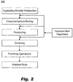
- Fig. 2 Other embodiments and/or aspects of this disclosure are shown in Fig. 2 .
- the systems and methods described herein can be used to clean powder (e.g., removing moisture and oxygen adsorbed by the powder) used for additive manufacturing (e.g., alloy powder), for example, Selective Laser Melting (SLM), Direct Metal Laser Sintering (DMLS), Electron Beam Melting (EBM), etc.
- SLM Selective Laser Melting
- DMLS Direct Metal Laser Sintering
- EBM Electron Beam Melting
- a powder cleaning system 100 can include a fluidized bed reactor 101 configured to retain powder 103 and fluidize the powder 103 to remove adsorbate (e.g., moisture, oxygen) and/or other contaminants (e.g., dirt or other impurity) from the powder 103.
- the system 100 can include one or more gas sources 105 configured to be in selective fluid communication with the fluidized bed reactor 101 via at least one inlet line 107 to selectively provide an inlet flow 109 having one or more gases to the fluidized bed reactor 101 to fluidize the powder 103 with the one or more gases within the fluidized bed reactor 101.
- the system 100 can include at least one outlet line 111 in fluid communication with the fluidized bed reactor 101 which can be configured to allow removal of outlet flow 113 which comprises the adsorbate and/or other contaminants from the fluidized bed reactor 101.
- the system 100 can include a filter 115 for capturing particles, the filter 115 disposed in the at least one outlet line 111.
- the system 100 can include a liquid trap 117 disposed downstream of the filter 115 and configured to trap liquid and/or powder entrained in the outlet flow 113.
- the liquid trap 117 can include a vent 119 for venting gas of the outlet flow 113, for example.
- the inlet line 107 can include at least one inlet line valve 121 configured to selectively allow flow from the one or more gas sources 105 to the fluidized bed reactor 101.
- the system 100 can include a bypass line 123 configured to fluidly connect the inlet line 107 and the liquid trap 117 to allow at least some gas in the inlet line 107 to flow to the vent 119.
- the bypass line 123 can include a bypass valve 125 configured to selectively allow bypass flow.
- the bypass line 123 and bypass valve 125 can be utilized to prevent pressure spikes in the fluidized bed reactor 101.
- the bypass valve 125 and the inlet line valve 121 can be a single three way valve to select between open, closed, or bypass, or to regulate between open and bypass states in any suitable manner.
- the system 100 can include a pressure release valve (PRV) 127 disposed in the inlet line 107 (e.g., downstream of the bypass line 123) and configured to allow bleeding of pressure above a threshold pressure.
- the PRV 127 can be or include a check valve, for example, or any other suitable valve (e.g., to actuate a threshold pressure to avoid overpressure of the reactor 101).
- the system 100 can include a pressure sensor 129 downstream of the PRV 127, for example, or in any other suitable location in the inlet line 127.
- the at least one inlet line valve 121 can be downstream of the pressure sensor 129.
- the one or more gas sources 105 can each include a source valve 131 and/or a mass flow controller (MFC) 133 for controlling an amount and/or proportion of each gas in the inlet flow 109.
- the one or more gas sources 105 can include at least one of an argon (Ar) source, an ammonia (NH 3 ) source, a nitrogen (N 2 ) source, a hydrogen (H 2 ) source, or a helium (He) source, or any combination thereof, e.g., as shown.
- the fluidized bed reactor 101 can include an outer housing 101a defining an outer space 101b and a powder container 101c disposed within the outer space 101b and defining an inner space 101d.
- the fluidized bed reactor 101 can include a gas distributor plate 101e between the outer space 101b and the inner space 101d at a bottom of the powder container 101c as shown.
- the gas distributor plate 101e can include a plurality of holes smaller than particles of the powder 103 configured to prevent powder 103 from falling through the plate 101e and to allow the inlet gas 109 to pass therethrough into the inner space 101d to fluidize the powder 103 within the powder container 101c.
- the inlet line 107 can be in fluid communication with the outer space 101b and the outlet line 111 can be in fluid communication with the inner space 101d such that inlet gas 109 must flow through the gas distributor plate 101e and the powder 103.
- a temperature sensor 135 can be disposed in thermal communication with the outer space 101b to sense a temperature of the inlet gas 109, and a temperature sensor 135 can be disposed in thermal communication with the outlet line 111 to sense a temperature of the outlet gas 113.
- the system 100 can include a heater or cooler disposed in thermal communication with the inlet flow 109 (e.g., in inlet line 107) to control a temperature of the inlet flow 109.
- the system can include a controller (not shown) operatively connected to each of the valves 121, 125, 131 and/or sensors 129, 135 to control a state of the system 100.
- the controller can include any suitable software and/or hardware modules to perform any suitable function, e.g., those disclosed herein.
- the controller can open the bypass valve 125 before or while opening one or more of the source valves 131 and/or inlet line valve 121 to prevent a pressure spike in the fluidization bed reactor 101.
- the controller can close the bypass valve 125 after steady state operation is reached either completely and/or partially to regulate pressure to the fluidization bed reactor 101.
- Any valve disclosed herein can be a shut off valve or a pressure regulating valve, or any other suitable valve.
- inlet line valve 121 can be configured to regulate pressure.
- the controller can be operatively connected to a heater or cooler to control the temperature of the inlet gas.
- the controller can include settings configured to provide a certain pressure, gas mixture or type, and temperature to the inlet flow 109 based on one or more powder characteristics (e.g., powder type, particle size, powder chemistry, amount of powder).
- a method 200 for cleaning a powder can include fluidizing powder in a fluidized bed reactor with an inlet gas to remove adsorbate and/or other contaminants to produce cleaned powder.
- Fluidizing powder includes flowing gas through the powder in a direction opposite to gravity.
- the inlet gas can include at least one of argon (Ar), ammonia (NH 3 ), nitrogen (N 2 ), hydrogen (H 2 ), or helium (He).
- fluidizing the powder can be performed after at least one of powder production, powder characterization and/or testing, and/or powder processing.
- Fluidizing powder can include controlling a temperature and/or pressure and/or a gas composition of the inlet gas as a function of one or more powder characteristics.
- the method can include sintering the cleaned powder to form an additively manufactured article.
- argon, nitrogen, and/or helium can be used for removing oxygen and moisture adsorbed by the powder, and ammonia, hydrogen, and/or nitrogen can be used to treat powder after removal of the adsorbed oxygen and moisture.
- ammonia, hydrogen, and/or nitrogen can be used to treat powder after removal of the adsorbed oxygen and moisture.
- Any single gas and/or any combination e.g., diluted ammonia can be used.
- Certain embodiments can utilize a fluidized bed reactor to displace undesirable adsorbed species (i.e. oxygen, moisture, etc.) on superalloy powder surfaces, for example.
- Embodiments of the reactor technique involve suspending solid particles by upward fluid flow. Rapid heat and mass transfer between the gas and solid particles can provide an alternative approach to other powder treatment methods.
- the treatment conditions i.e. fluidization velocity, temperature, time, gas compositions, etc.
- the treatment conditions i.e. fluidization velocity, temperature, time, gas compositions, etc.
- the treatment conditions i.e. fluidization velocity, temperature, time, gas compositions, etc.
- the superalloy powder properties e.g. particle diameter, density, etc.
- Embodiments provide a flexible, economically feasible, and scalable method of uniform particle mixing and temperature gradients. Embodiments can remove surface oxygen without affecting bulk structure or morphology.
- the first step in powder metallurgy (PM) processes can be the fabrication of metal powders. Removal of surface oxygen by fluidized bed gas reaction can be implemented at a several stages during the fabrication process as well as along the pathway of generating a finished part.
- Example processes used in powder production include solid-state reduction, atomization, electrolysis, and chemical.
- an ore material is first crushed (usually mixed with carbon), and passed through a furnace whereby the carbon and oxygen are reduced from the powder leaving behind a compacted sponge metal which crushed, separated from all non-metallic material, and sieved.
- molten metal is separated into small droplets and frozen rapidly before the drops come into contact with each other or with a solid surface.
- the technique is applicable to all metals that can be melted.
- Electrolysis is carried out by selecting conditions, such as electrolyte composition and concentration, temperature, and current density, many metals current density whereby metals are deposited in a spongy or powdery state. Subsequent processing such as washing, drying, reducing, annealing, and crushing is often required to produce high-purity and high-density powders. However, due to high energy costs, this process is typically limited to high-value powders.
- the chemical method is the most common whereby chemical powder treatments involve oxide reduction, precipitation from solutions, and thermal decomposition.
- the powders produced can have a great variation in properties and yet have closely controlled particle size and shape.
- Embodiments can be used as post-processing stage associated with any of the processes mentioned above, for example, to generate low oxygen/moisture surfaces. Embodiments can be used at any other suitable point, e.g., before sintering of the powder.
- aspects of the present disclosure may be embodied as a system, method, or computer program product. Accordingly, aspects of this disclosure may take the form of an entirely hardware embodiment, an entirely software embodiment (including firmware, resident software, micro-code, etc.), or an embodiment combining software and hardware aspects, all possibilities of which can be referred to herein as a "circuit,” “module,” or “system.”
- a “circuit,” “module,” or “system” can include one or more portions of one or more separate physical hardware and/or software components that can together perform the disclosed function of the "circuit,” “module,” or “system”, or a “circuit,” “module,” or “system” can be a single self-contained unit (e.g., of hardware and/or software).
- aspects of this disclosure may take the form of a computer program product embodied in one or more computer readable medium(s) having computer readable program code embodied thereon.
- the computer readable medium may be a computer readable signal medium or a computer readable storage medium.
- a computer readable storage medium may be, for example, but not limited to, an electronic, magnetic, optical, electromagnetic, infrared, or semiconductor system, apparatus, or device, or any suitable combination of the foregoing.
- a computer readable storage medium may be any tangible medium that can contain, or store a program for use by or in connection with an instruction execution system, apparatus, or device.
- a computer readable signal medium may include a propagated data signal with computer readable program code embodied therein, for example, in baseband or as part of a carrier wave. Such a propagated signal may take any of a variety of forms, including, but not limited to, electro-magnetic, optical, or any suitable combination thereof.
- a computer readable signal medium may be any computer readable medium that is not a computer readable storage medium and that can communicate, propagate, or transport a program for use by or in connection with an instruction execution system, apparatus, or device.
- Program code embodied on a computer readable medium may be transmitted using any appropriate medium, including but not limited to wireless, wireline, optical fiber cable, RF, etc., or any suitable combination of the foregoing.
- Computer program code for carrying out operations for aspects of this disclosure may be written in any combination of one or more programming languages, including an object oriented programming language such as Java, Smalltalk, C++ or the like and conventional procedural programming languages, such as the "C" programming language or similar programming languages.
- the program code may execute entirely on the user's computer, partly on the user's computer, as a stand-alone software package, partly on the user's computer and partly on a remote computer or entirely on the remote computer or server.
- the remote computer may be connected to the user's computer through any type of network, including a local area network (LAN) or a wide area network (WAN), or the connection may be made to an external computer (for example, through the Internet using an Internet Service Provider).
- LAN local area network
- WAN wide area network
- Internet Service Provider for example, AT&T, MCI, Sprint, EarthLink, MSN, GTE, etc.
- These computer program instructions may also be stored in a computer readable medium that can direct a computer, other programmable data processing apparatus, or other devices to function in a particular manner, such that the instructions stored in the computer readable medium produce an article of manufacture including instructions which implement the function/act specified in the flowchart and/or block diagram block or blocks.
- the computer program instructions may also be loaded onto a computer, other programmable data processing apparatus, or other devices to cause a series of operational steps to be performed on the computer, other programmable apparatus or other devices to produce a computer implemented process such that the instructions which execute on the computer or other programmable apparatus provide processes for implementing the functions/acts specified herein.
- any numerical values disclosed herein can be exact values or can be values within a range. Further, any terms of approximation (e.g., “about”, “approximately”, “around”) used in this disclosure can mean the stated value within a range. For example, in certain embodiments, the range can be within (plus or minus) 20%, or within 10%, or within 5%, or within 2%, or within any other suitable percentage or number as appreciated by those having ordinary skill in the art (e.g., for known tolerance limits or error ranges).
Landscapes
- Chemical & Material Sciences (AREA)
- Engineering & Computer Science (AREA)
- Organic Chemistry (AREA)
- Chemical Kinetics & Catalysis (AREA)
- Combustion & Propulsion (AREA)
- Manufacturing & Machinery (AREA)
- Materials Engineering (AREA)
- Devices And Processes Conducted In The Presence Of Fluids And Solid Particles (AREA)
Applications Claiming Priority (1)
| Application Number | Priority Date | Filing Date | Title |
|---|---|---|---|
| US16/194,830 US11097340B2 (en) | 2018-11-19 | 2018-11-19 | Powder cleaning systems and methods |
Publications (1)
| Publication Number | Publication Date |
|---|---|
| EP3653291A1 true EP3653291A1 (de) | 2020-05-20 |
Family
ID=68581590
Family Applications (1)
| Application Number | Title | Priority Date | Filing Date |
|---|---|---|---|
| EP19209151.0A Pending EP3653291A1 (de) | 2018-11-19 | 2019-11-14 | Pulverreinigungssysteme und -verfahren |
Country Status (2)
| Country | Link |
|---|---|
| US (2) | US11097340B2 (de) |
| EP (1) | EP3653291A1 (de) |
Families Citing this family (2)
| Publication number | Priority date | Publication date | Assignee | Title |
|---|---|---|---|---|
| EP4049831A1 (de) * | 2017-07-21 | 2022-08-31 | CL Schutzrechtsverwaltungs GmbH | Vorrichtung zur generativen fertigung dreidimensionaler objekte |
| SI26550A (sl) * | 2023-10-27 | 2025-04-30 | FerroČrtalič d.o.o. | Naprava in postopek za odpraševanje predsintranih izdelkov narejenih po metodi selektivnega brizganja veziva |
Citations (7)
| Publication number | Priority date | Publication date | Assignee | Title |
|---|---|---|---|---|
| JPH0889785A (ja) * | 1994-09-21 | 1996-04-09 | Ishihara Sangyo Kaisha Ltd | 固体粒子粉末の処理方法 |
| EP0900590A1 (de) * | 1997-09-05 | 1999-03-10 | Mitsui Chemicals, Inc. | Verfahren zur Gasflussratenregelung in einer Vorrichtung zur Gasphasenpolymerisation und Vorrichtung zur Gasphasenpolymerisation |
| DE19921059A1 (de) * | 1999-05-07 | 2000-11-16 | Heraeus Quarzglas | Verfahren zum Reinigen von Si0¶2¶-Partikeln, Vorrichtung zur Durchführung des Verfahrens, und nach dem Verfahren hergestellte Körnung |
| EP1942078A1 (de) * | 2005-10-28 | 2008-07-09 | Japan Super Quartz Corporation | Verfahren zur reinigung von silikapartikeln, reiniger und gereinigte silika-partikel |
| US20140216586A1 (en) * | 2011-09-12 | 2014-08-07 | Toyo Tanso Co., Ltd. | Powder processing apparatus and powder processing method |
| WO2015023438A1 (en) * | 2013-08-12 | 2015-02-19 | United Technologies Corporation | Powder spheroidizing via fluidized bed |
| WO2016118551A1 (en) * | 2015-01-21 | 2016-07-28 | Sikorsky Aircraft Corporation | Cold spray process using treated metal powder |
Family Cites Families (10)
| Publication number | Priority date | Publication date | Assignee | Title |
|---|---|---|---|---|
| US7776129B2 (en) | 2007-04-24 | 2010-08-17 | Chemical Vapour Metal Refining Inc. | Apparatus and process for making high purity nickel |
| DE102010022773B4 (de) | 2010-06-04 | 2012-10-04 | Outotec Oyj | Verfahren und Anlage zur Erzeugung von Roheisen |
| CN105142830B (zh) * | 2013-04-24 | 2018-04-20 | 联合工艺公司 | 用于脱气和热处理粉末的流化床 |
| WO2015023439A1 (en) | 2013-08-12 | 2015-02-19 | United Technologies Corporation | High temperature fluidized bed for powder treatment |
| EP3083084A4 (de) * | 2013-12-18 | 2017-08-16 | United Technologies Corporation | Pulverklassifizierungssystem und -verfahren |
| US10011892B2 (en) | 2014-08-21 | 2018-07-03 | Honeywell International Inc. | Methods for producing alloy forms from alloys containing one or more extremely reactive elements and for fabricating a component therefrom |
| US9732422B2 (en) * | 2015-01-23 | 2017-08-15 | United Technologies Corporation | Method of coating metallic powder particles |
| US10330019B2 (en) * | 2015-02-25 | 2019-06-25 | Hamilton Sundstrand Corporation | Self-actuating and dual pivot flapper valve |
| US10041171B2 (en) * | 2015-08-10 | 2018-08-07 | Delavan Inc. | Particulates for additive manufacturing techniques |
| US20190160528A1 (en) * | 2017-11-27 | 2019-05-30 | Hamilton Sundstrand Corporation | Method and apparatus for improving powder flowability |
-
2018
- 2018-11-19 US US16/194,830 patent/US11097340B2/en active Active
-
2019
- 2019-11-14 EP EP19209151.0A patent/EP3653291A1/de active Pending
-
2021
- 2021-08-05 US US17/394,631 patent/US11980880B2/en active Active
Patent Citations (7)
| Publication number | Priority date | Publication date | Assignee | Title |
|---|---|---|---|---|
| JPH0889785A (ja) * | 1994-09-21 | 1996-04-09 | Ishihara Sangyo Kaisha Ltd | 固体粒子粉末の処理方法 |
| EP0900590A1 (de) * | 1997-09-05 | 1999-03-10 | Mitsui Chemicals, Inc. | Verfahren zur Gasflussratenregelung in einer Vorrichtung zur Gasphasenpolymerisation und Vorrichtung zur Gasphasenpolymerisation |
| DE19921059A1 (de) * | 1999-05-07 | 2000-11-16 | Heraeus Quarzglas | Verfahren zum Reinigen von Si0¶2¶-Partikeln, Vorrichtung zur Durchführung des Verfahrens, und nach dem Verfahren hergestellte Körnung |
| EP1942078A1 (de) * | 2005-10-28 | 2008-07-09 | Japan Super Quartz Corporation | Verfahren zur reinigung von silikapartikeln, reiniger und gereinigte silika-partikel |
| US20140216586A1 (en) * | 2011-09-12 | 2014-08-07 | Toyo Tanso Co., Ltd. | Powder processing apparatus and powder processing method |
| WO2015023438A1 (en) * | 2013-08-12 | 2015-02-19 | United Technologies Corporation | Powder spheroidizing via fluidized bed |
| WO2016118551A1 (en) * | 2015-01-21 | 2016-07-28 | Sikorsky Aircraft Corporation | Cold spray process using treated metal powder |
Also Published As
| Publication number | Publication date |
|---|---|
| US11097340B2 (en) | 2021-08-24 |
| US20200156149A1 (en) | 2020-05-21 |
| US11980880B2 (en) | 2024-05-14 |
| US20210362226A1 (en) | 2021-11-25 |
Similar Documents
| Publication | Publication Date | Title |
|---|---|---|
| US11980880B2 (en) | Powder cleaning systems and methods | |
| JP5025085B2 (ja) | 金属物品を融解せずに製造する方法 | |
| EP2988895B1 (de) | Wirbelschicht zur entgasung und wärmebehandlung von pulvern | |
| TWI454588B (zh) | FePt-C sputtering target and its manufacturing method | |
| US10239097B2 (en) | Method and apparatus for the recovery and regeneration of metal powder in EBM applications | |
| Soundarapandiyan et al. | A technical review of the challenges of powder recycling in the laser powder bed fusion additive manufacturing process | |
| CN109563564B (zh) | 制造装置和方法 | |
| CN105377476B (zh) | 用于粉末处理的高温流化床 | |
| US20120325051A1 (en) | Production of atomized powder for glassy aluminum-based alloys | |
| CN103071796A (zh) | 选择性激光熔化slm气氛保护系统 | |
| CN110614376A (zh) | 一种3d打印用钨铜复合粉末的制备方法 | |
| CN102959101B (zh) | 用于矿体的热处理的系统和方法 | |
| US20200254523A1 (en) | Three-dimensional printer with two state filter for powdered metal | |
| US11826828B2 (en) | Gas supply device for manufacturing device. atomizing device, 3D additive manufacturing device, additive manufacturing system, and shaped object and gas supply method for manufacturing device | |
| TW201219132A (en) | Potassium/molybdenum composite metal powders, powder blends, products thereof, and methods for producing photovoltaic cells | |
| Ulianitsky et al. | Structure and composition of Fe-Co-Ni and Fe-Co-Ni-Cu coatings obtained by detonation spraying of powder mixtures | |
| CN119156251A (zh) | 具有能单独分开的过滤腔的过滤系统 | |
| JP5103023B2 (ja) | 液体と粉体の混合装置、金属回収システム、液体と粉体の混合方法、及び、金属回収方法 | |
| KR102037349B1 (ko) | 티타늄 분말 제조용 탈산 장치 | |
| JPS58171506A (ja) | 微細な金属ニツケル粉末の製造方法 | |
| JP2019219083A (ja) | 流動焙焼炉 | |
| CN108746605B (zh) | 一种用于钼硅硼材料增材制造的除氧成型腔和除氧装置及方法 | |
| CN112756619A (zh) | 一种亚微米级可控元素比例CuSn合金粉的生产方法 | |
| JP2018012625A (ja) | 酸化ニッケルの製造方法、流動焙焼炉 | |
| JP3841547B2 (ja) | 銅合金粉末の製造方法、並びにその銅合金粉末を用いたレーザ肉盛り方法 |
Legal Events
| Date | Code | Title | Description |
|---|---|---|---|
| PUAI | Public reference made under article 153(3) epc to a published international application that has entered the european phase |
Free format text: ORIGINAL CODE: 0009012 |
|
| STAA | Information on the status of an ep patent application or granted ep patent |
Free format text: STATUS: THE APPLICATION HAS BEEN PUBLISHED |
|
| AK | Designated contracting states |
Kind code of ref document: A1 Designated state(s): AL AT BE BG CH CY CZ DE DK EE ES FI FR GB GR HR HU IE IS IT LI LT LU LV MC MK MT NL NO PL PT RO RS SE SI SK SM TR |
|
| AX | Request for extension of the european patent |
Extension state: BA ME |
|
| RIN1 | Information on inventor provided before grant (corrected) |
Inventor name: MCGEE, RANDOLPH CARLTON Inventor name: SHE, YING |
|
| STAA | Information on the status of an ep patent application or granted ep patent |
Free format text: STATUS: REQUEST FOR EXAMINATION WAS MADE |
|
| 17P | Request for examination filed |
Effective date: 20201120 |
|
| RBV | Designated contracting states (corrected) |
Designated state(s): AL AT BE BG CH CY CZ DE DK EE ES FI FR GB GR HR HU IE IS IT LI LT LU LV MC MK MT NL NO PL PT RO RS SE SI SK SM TR |
|
| STAA | Information on the status of an ep patent application or granted ep patent |
Free format text: STATUS: EXAMINATION IS IN PROGRESS |
|
| 17Q | First examination report despatched |
Effective date: 20230131 |