EP3652018B1 - Längseinsteller für einen fahrzeugsitz sowie fahrzeugsitz - Google Patents
Längseinsteller für einen fahrzeugsitz sowie fahrzeugsitz Download PDFInfo
- Publication number
- EP3652018B1 EP3652018B1 EP18736861.8A EP18736861A EP3652018B1 EP 3652018 B1 EP3652018 B1 EP 3652018B1 EP 18736861 A EP18736861 A EP 18736861A EP 3652018 B1 EP3652018 B1 EP 3652018B1
- Authority
- EP
- European Patent Office
- Prior art keywords
- seat
- longitudinal adjuster
- rack
- rail
- longitudinal
- Prior art date
- Legal status (The legal status is an assumption and is not a legal conclusion. Google has not performed a legal analysis and makes no representation as to the accuracy of the status listed.)
- Active
Links
- 230000005540 biological transmission Effects 0.000 description 6
- 239000002184 metal Substances 0.000 description 6
- 238000005452 bending Methods 0.000 description 3
- 230000000903 blocking effect Effects 0.000 description 3
- 230000000694 effects Effects 0.000 description 2
- 230000003993 interaction Effects 0.000 description 2
- 238000000034 method Methods 0.000 description 2
- 239000011324 bead Substances 0.000 description 1
- 230000010354 integration Effects 0.000 description 1
- 238000004519 manufacturing process Methods 0.000 description 1
- 230000013011 mating Effects 0.000 description 1
Images

Classifications
-
- B—PERFORMING OPERATIONS; TRANSPORTING
- B60—VEHICLES IN GENERAL
- B60N—SEATS SPECIALLY ADAPTED FOR VEHICLES; VEHICLE PASSENGER ACCOMMODATION NOT OTHERWISE PROVIDED FOR
- B60N2/00—Seats specially adapted for vehicles; Arrangement or mounting of seats in vehicles
- B60N2/02—Seats specially adapted for vehicles; Arrangement or mounting of seats in vehicles the seat or part thereof being movable, e.g. adjustable
- B60N2/04—Seats specially adapted for vehicles; Arrangement or mounting of seats in vehicles the seat or part thereof being movable, e.g. adjustable the whole seat being movable
- B60N2/06—Seats specially adapted for vehicles; Arrangement or mounting of seats in vehicles the seat or part thereof being movable, e.g. adjustable the whole seat being movable slidable
- B60N2/07—Slide construction
- B60N2/0702—Slide construction characterised by its cross-section
- B60N2/0715—C or U-shaped
-
- B—PERFORMING OPERATIONS; TRANSPORTING
- B60—VEHICLES IN GENERAL
- B60N—SEATS SPECIALLY ADAPTED FOR VEHICLES; VEHICLE PASSENGER ACCOMMODATION NOT OTHERWISE PROVIDED FOR
- B60N2/00—Seats specially adapted for vehicles; Arrangement or mounting of seats in vehicles
- B60N2/005—Arrangement or mounting of seats in vehicles, e.g. dismountable auxiliary seats
- B60N2/015—Attaching seats directly to vehicle chassis
-
- B—PERFORMING OPERATIONS; TRANSPORTING
- B60—VEHICLES IN GENERAL
- B60N—SEATS SPECIALLY ADAPTED FOR VEHICLES; VEHICLE PASSENGER ACCOMMODATION NOT OTHERWISE PROVIDED FOR
- B60N2/00—Seats specially adapted for vehicles; Arrangement or mounting of seats in vehicles
- B60N2/02—Seats specially adapted for vehicles; Arrangement or mounting of seats in vehicles the seat or part thereof being movable, e.g. adjustable
- B60N2/0224—Non-manual adjustments, e.g. with electrical operation
- B60N2/02246—Electric motors therefor
-
- B—PERFORMING OPERATIONS; TRANSPORTING
- B60—VEHICLES IN GENERAL
- B60N—SEATS SPECIALLY ADAPTED FOR VEHICLES; VEHICLE PASSENGER ACCOMMODATION NOT OTHERWISE PROVIDED FOR
- B60N2/00—Seats specially adapted for vehicles; Arrangement or mounting of seats in vehicles
- B60N2/02—Seats specially adapted for vehicles; Arrangement or mounting of seats in vehicles the seat or part thereof being movable, e.g. adjustable
- B60N2/04—Seats specially adapted for vehicles; Arrangement or mounting of seats in vehicles the seat or part thereof being movable, e.g. adjustable the whole seat being movable
- B60N2/06—Seats specially adapted for vehicles; Arrangement or mounting of seats in vehicles the seat or part thereof being movable, e.g. adjustable the whole seat being movable slidable
- B60N2/067—Seats specially adapted for vehicles; Arrangement or mounting of seats in vehicles the seat or part thereof being movable, e.g. adjustable the whole seat being movable slidable by linear actuators, e.g. linear screw mechanisms
-
- B—PERFORMING OPERATIONS; TRANSPORTING
- B60—VEHICLES IN GENERAL
- B60N—SEATS SPECIALLY ADAPTED FOR VEHICLES; VEHICLE PASSENGER ACCOMMODATION NOT OTHERWISE PROVIDED FOR
- B60N2/00—Seats specially adapted for vehicles; Arrangement or mounting of seats in vehicles
- B60N2/02—Seats specially adapted for vehicles; Arrangement or mounting of seats in vehicles the seat or part thereof being movable, e.g. adjustable
- B60N2/04—Seats specially adapted for vehicles; Arrangement or mounting of seats in vehicles the seat or part thereof being movable, e.g. adjustable the whole seat being movable
- B60N2/06—Seats specially adapted for vehicles; Arrangement or mounting of seats in vehicles the seat or part thereof being movable, e.g. adjustable the whole seat being movable slidable
- B60N2/07—Slide construction
- B60N2/0702—Slide construction characterised by its cross-section
- B60N2/0705—Slide construction characterised by its cross-section omega-shaped
-
- B—PERFORMING OPERATIONS; TRANSPORTING
- B60—VEHICLES IN GENERAL
- B60N—SEATS SPECIALLY ADAPTED FOR VEHICLES; VEHICLE PASSENGER ACCOMMODATION NOT OTHERWISE PROVIDED FOR
- B60N2/00—Seats specially adapted for vehicles; Arrangement or mounting of seats in vehicles
- B60N2/24—Seats specially adapted for vehicles; Arrangement or mounting of seats in vehicles for particular purposes or particular vehicles
- B60N2/42—Seats specially adapted for vehicles; Arrangement or mounting of seats in vehicles for particular purposes or particular vehicles the seat constructed to protect the occupant from the effect of abnormal g-forces, e.g. crash or safety seats
- B60N2/43—Safety locks
Definitions
- the invention relates to a longitudinal adjuster for a vehicle seat, in particular a motor vehicle seat, having at least one pair of rails, which is formed from a first seat rail, in particular for connection to a seat structure, and a second seat rail, in particular for connection to a vehicle structure, the seat rails of the pair of rails are displaceable in the longitudinal direction relative to one another and alternately engage around one another to form an inner channel.
- a securing profile attached to the first seat rail is arranged in the inner channel, and a toothed rack fixed relative to the second seat rail is also arranged in the inner channel.
- the securing profile and the toothed rack are normally spaced apart from one another and come into positive engagement with one another in response to a predetermined force, for example in the event of a crash.
- the invention also relates to a vehicle seat.
- the longitudinal adjuster comprises two seat rails that can be displaced relative to one another, namely an upper rail and a lower rail, which mutually engage around one another.
- the seat rails each include stop means, the stop means creating an additional connection between the upper rail and the lower rail in the event of a crash. In the event of a crash, forces are then additionally introduced into the vehicle structure via the aforementioned stop means from the upper rail and the lower rail.
- a slide rail guide for vehicle seats is known, with a stationary outer rail and a movable inner rail on which a web is arranged as a brake rail.
- a blocking device is attached to the outer rail on both sides of the brake rail. In the event of a crash (e.g. front crash, rear impact), blocking elements of the blocking device are deflected against the brake rail and cause a blockage so that the inner and outer rails are locked together.
- a support for a vehicle seat which is guided on seat guide rails attached to the vehicle floor on both sides of the seat.
- at least one support rail is provided between the two seat guide rails, which is firmly connected to the vehicle floor.
- This support rail is assigned a securing part which is firmly connected to the seat frame and which, however, does not touch the support rail under normal load.
- the support rail has a locking toothing pointing towards the seat frame and a support track.
- the securing part has locking means and a support surface.
- the deformation of the seat frame causes the locking teeth and the locking means to engage and prevent further deformations and the forward movement of the seat.
- the support surface rests on the support track and prevents impermissible deformations.
- a vehicle seat longitudinal adjustment device in which an upper rail is slidably guided in a lower rail and is moved by a motor through the interaction of a rotatably mounted drive pinion, which is assigned to one rail, and a rack, which is assigned to the other rail, with an additional locking being provided, which is normally ineffective and only locks the upper rail with the lower rail in the event of a crash, in the event of a crash there is a relative movement between the bearing of the drive pinion and / or the rack on the one hand and the associated rail on the other hand, whereby the additional lock is locked.
- a rail device for a vehicle seat comprising a first and a second rail which are mounted longitudinally displaceably relative to one another, further comprising a lock which is movably mounted between an unlocked position and a locked position, the lock being the first and the makes second rail immovable relative to one another, the first rail having an axis integral with the lock, the axis allowing a rotation of the lock relative to the first rail about a direction perpendicular to the longitudinal direction in the event of a predetermined impact, so that the lock allows the entire mobility the sliding relative to each other permanently cancels, wherein the pawl has lateral teeth which, in the event of a predetermined impact, exit through windows arranged on the first rail and facing the teeth and come into contact with the second rail.
- a method for producing a fastening element of a longitudinal adjuster for a vehicle seat is known. According to the method, in a first step a cut wire is compressed into a blank and in a second step the blank is pressed to form the fastening element with a final outer contour.
- a transmission unit of an adjusting device of a motor vehicle which is designed and provided for actuating an adjustment part of the motor vehicle, with a transmission housing, with a transmission assembly mounted on the transmission housing, the elements of which are at least partially arranged within the transmission housing, with a longitudinally extending transmission part that at least on one side protrudes from the gear housing, and with a holder which engages around the gear housing and which has at least one through opening through which the elongated gear part extends.
- the invention is based on the object of improving a longitudinal adjuster of the type mentioned at the beginning, in particular to increase the strength of the longitudinal adjuster in the event of a crash, and to provide a corresponding vehicle seat.
- a longitudinal adjuster for a vehicle seat in particular a motor vehicle seat, having at least one pair of rails, which is formed from a first seat rail, in particular for connection to a seat structure, and a second seat rail, in particular for connection to a vehicle structure.
- the seat rails of the pair of rails can be displaced in the longitudinal direction relative to one another and alternately engage around one another to form an inner channel.
- a securing profile attached to the first seat rail is arranged in the inner channel, and a toothed rack fixed relative to the second seat rail is also arranged in the inner channel.
- the securing profile and the rack are normally spaced apart from one another and, in response to a predetermined force, for example in the event of a crash, come into positive engagement with one another, the securing profile engaging around the rack.
- a securing profile is attached to the first seat rail in the inner channel and a toothed rack is also arranged in the inner channel, the securing profile and the toothed rack being normally spaced apart and in response to a predetermined force, for example in the event of a crash, in a form-fitting manner Intervention, it is made possible in a particularly advantageous manner that the load capacity of the longitudinal adjuster, in particular in so-called belt integration seats, can be increased both in the vertical direction and in the longitudinal direction in situations with comparatively very high crash loads. Furthermore, according to the proposed solution, a load is placed on a conventional rail lock for setting a longitudinal seat position reduced, so that overloading of the rail lock is prevented. It is also advantageous that an additional load pick-up by means of the securing profile and the toothed rack is only active in the event of a crash and there are no restrictions during normal use of the longitudinal adjuster.
- the rack can have teeth with downwardly directed teeth.
- the toothed rack can be connected, in particular welded, to the second seat rail at least in a front section, in particular by means of an adapter.
- the rack can be led out of the inner channel to the rear and can be connected to a vehicle structure in a rear section, in particular by means of an adapter.
- the teeth of the tooth system can each have two tooth flanks which are inclined towards one another in the direction of a tooth tip.
- the teeth can have a rectangular or trapezoidal cross-section.
- the toothing of the rack can be helical.
- the downward facing surface of the rack can be curved.
- the toothing can be part of a thread.
- the rack can be a threaded rod.
- the rack can be a spindle.
- the teeth can have a tooth thickness in the range from 0.15 mm to 5 mm, in particular an average tooth thickness in the range from 0.15 mm to 5 mm mm.
- An average tooth thickness is understood to mean the tooth thickness in the region of half the tooth height.
- the tooth thickness can generally preferably be dimensioned in such a way that, in the event of a crash, deformation of the teeth due to the engagement of the securing profile is prevented.
- the teeth can have a tooth height in the range from 0.25 mm to 5 mm, preferably in the range from 0.3 mm to 1 mm.
- the tooth height and thereby also a depth of the tooth gaps can generally preferably be dimensioned in such a way that in the event of a crash a sufficient depth of the tooth gaps is provided for the engagement of the securing profile.
- the securing profile can have a substantially L-shaped cross section.
- the securing profile can be screwed to the first seat rail, in particular in a horizontal section.
- the securing profile can have a through opening, in particular in a vertical section.
- the securing profile engages around the rack.
- the rack can penetrate the through opening of the safety profile.
- the securing profile can, in particular in the area of a lower wall of the through opening, have counter-toothing cooperating with the toothing of the rack.
- a tooth spacing between two adjacent teeth can be greater than the thickness of the securing profile, in particular a vertical section of the securing profile.
- a vehicle seat with a longitudinal adjuster described above the vehicle seat having a seat structure which is connected to a first seat rail of the longitudinal adjuster.
- a longitudinal direction x runs largely horizontally and preferably parallel to a vehicle longitudinal direction which corresponds to the normal direction of travel of the vehicle.
- a transverse direction y running perpendicular to the longitudinal direction x is also oriented horizontally in the vehicle and runs parallel to a transverse direction of the vehicle.
- a vertical direction z runs perpendicular to the longitudinal direction x and perpendicular to the transverse direction y. In the case of a vehicle seat 1 installed in the vehicle, the vertical direction z runs parallel to the vertical axis of the vehicle.
- the position information and direction information used such as front, rear, top and bottom refer to a line of sight of an occupant sitting in the vehicle seat 1 in the normal sitting position, the vehicle seat 1 being installed in the vehicle, in a position of use suitable for passenger transport with the backrest 4 and upright is aligned in the direction of travel as usual.
- the vehicle seat 1 can, however, also be installed in a different orientation, for example transversely to the direction of travel.
- the vehicle seat 1 shown for a motor vehicle has a seat part 2 and a backrest 4 whose inclination is adjustable relative to the seat part 2.
- the inclination of the backrest 4 can be adjustable, for example, by means of a locking fitting or a gear fitting.
- the vehicle seat 1 is for setting a Longitudinal seat position mounted on a longitudinal adjuster 10.
- the longitudinal adjuster 10 has a pair of rails 12.
- the pair of rails 12 is formed from a first seat rail 14, in particular for connection to a seat structure, and a second seat rail 16, in particular for connection to a vehicle structure.
- the seat rails 14, 16 of the pair of rails 12 can be displaced relative to one another in the longitudinal direction x.
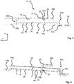
- Fig. 2 shows the pair of rails 12 of the longitudinal adjuster 10 according to the invention for the vehicle seat 1 from Fig. 1 .
- the pair of rails 12 comprises a first seat rail 14, in particular for connection to a seat structure, and a second seat rail 16, in particular for connection to a vehicle structure.
- the seat rails 14, 16 of the pair of rails 12 can be displaced relative to one another in the longitudinal direction x and reciprocally engage around one another to form an inner channel 18.
- a securing profile 50 is fastened to the first seat rail 14 in the inner channel 18, in particular to a rear end of the first seat rail 14.
- a toothed rack 40 is also arranged in the inner channel 18.
- the rear end of the second seat rail 16 is encompassed by a profiled sheet metal 20.
- the profiled sheet 20 is a bent sheet metal part, in particular a profiled sheet 20 bent essentially in a U-shape.
- the profiled sheet 20 is pushed onto the second seat rail 16 from below and is preferably firmly connected to the second seat rail 16.
- the profiled sheet metal 20 is preferably welded to the second seat rail 16.
- the profiled sheet metal 20 has a plurality of beads which increase the rigidity of the profiled sheet metal 20.
- Fig. 3 shows a longitudinal section of the pair of rails 12 according to a first embodiment.
- Fig. 4 shows the rack 40 and the securing profile 50 of the pair of rails 12 of FIG Fig. 3 in a perspective view.
- the toothed rack 40 has teeth with downwardly directed teeth 44.
- the toothed rack 40 is connected to the second seat rail 16 in a front section 40a.
- the toothed rack 40 is connected to the second seat rail 16 in a front section 40a by means of an adapter 42a.
- the The rack 40 is welded to the second seat rail 16.
- the rack 40 is led out of the inner channel 18 at a rear end of the pair of rails 12.
- the rack 40 can be connected to a vehicle structure in a rear section 40b.
- the rack 40 can be connected to a vehicle structure in the rear section 40b by means of an adapter 42b.
- the rack 40 can be screwed to the vehicle structure.
- the securing profile 50 has a substantially L-shaped cross section.
- the securing profile 50 can be screwed to the first seat rail 14.
- a horizontal section 50a of the securing profile 50 can be screwed to the first seat rail 14.
- the securing profile 50 has a through opening 52.
- a vertical section 50b of the securing profile 50 has a through opening 52.
- the securing profile 50 engages around the rack 40.
- the rack 40 penetrates the through opening 52 of the securing profile 50.
- the securing profile 50 and the rack 40 are normally spaced from one another. In response to a predetermined force, for example in the event of a crash, they come into positive engagement with one another.
- the teeth 44 of the toothed rack 40 have a tooth thickness d in the range from 3 mm to 5 mm.
- a load capacity of the tooth engagement is essentially defined by the tooth thickness d in connection with the number of loaded teeth.
- the teeth 44 in the present case have a tooth height h in the range from 2.5 mm to 5 mm.
- the teeth 44 have a tooth spacing a in the range from 3.5 mm to 6 mm.
- a tooth spacing a between two adjacent teeth 44 is greater than the thickness of the vertical section 50b of the securing profile 50.
- the teeth 44 can have a rectangular or trapezoidal cross-section.
- the teeth 44 of the toothing each have two tooth flanks 46 which are inclined towards one another in the direction of a tooth tip 48.
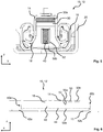
- Fig. 5 shows a cross section of the pair of rails 12 according to the first embodiment.
- the vertical section 50b of the securing profile 50 has an outer contour which, while forming a gap, follows the inner contour of the first seat rail 14 in sections.
- the vertical section 50b of the securing profile 50 almost completely fills the cross section of the inner channel 18, forming a gap that runs around the circumference in sections.
- the vertical section 50b of the securing profile 50 serves to prevent the two outer sections of the first seat rail 14 in the transverse direction y from bending inward.
- the profiled sheet metal 20, which engages around the second seat rail 16 from below serves to prevent the outer legs of the second seat rail 16 from bending apart when viewed in the transverse direction y.
- the interaction of the securing profile 50 and the profile sheet 20 prevents the seat rails 14, 16 from peeling off, a so-called peeling effect.
- This peeling effect is also reduced, if not even prevented, by the action of the securing profile 50 in conjunction with the rack 40, in that the force acting upward on the first seat rail 14 in the vertical direction z is diverted via the rack 40 into the vehicle structure.
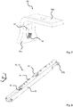
- Fig. 6 shows the pair of rails 12 according to a second embodiment.
- the toothing of the rack 40 according to the second embodiment is a helical toothing.
- the helical toothing can be produced by means of a thread cutting tool. It is also conceivable that the toothed rack 40 according to the second embodiment is a threaded spindle.
- the teeth 44 of the toothing have a tooth thickness in the range from 0.15 mm to 2 mm.
- the teeth 44 have a tooth height in the range from 0.25 mm to 1.5 mm.
- Fig. 7 shows the securing profile 40 according to the second embodiment.
- the securing profile 50 has, at least in the area of a lower wall of the through opening 52, a counter-toothing 54 cooperating with the toothing of the rack 40.
- a dimensioning of the counter-toothing 54 essentially corresponds to a dimensioning of the teeth 44 of the toothing.
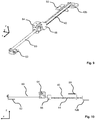
- the Figures 8 to 10 show different parts of the longitudinal adjuster 10 according to a third exemplary embodiment.
- the longitudinal adjuster 10 has a spindle 60 in the inner channel 18 and an adjusting gear 64 that can be moved along the spindle.
- the adjusting gear 64 can be driven by means of a motor (not shown).
- the spindle 60 in particular a front end section of the spindle 60, is preferably firmly connected to the second seat rail 16 by means of a spindle holder 62.
- the rack 40 is arranged in the longitudinal direction x in alignment behind the spindle 60.
- the spindle 60 and the rack 40 are connected to one another by means of a connection adapter 66.
- the connection adapter 66 can be fixed in the second seat rail 16.
- the connection adapter 66 can serve as a rear end stop.
Description
- Die Erfindung betrifft einen Längseinsteller für einen Fahrzeugsitz, insbesondere Kraftfahrzeugsitz, aufweisend mindestens ein Schienenpaar, welches aus einer ersten Sitzschiene, insbesondere zur Verbindung mit einer Sitzstruktur, und einer zweiten Sitzschiene, insbesondere zur Verbindung mit einer Fahrzeugstruktur, gebildet ist, wobei die Sitzschienen des Schienenpaares in Längsrichtung relativ zueinander verschiebbar sind und unter Bildung eines Innenkanals einander wechselseitig umgreifen. In dem Innenkanal ist ein an der ersten Sitzschiene befestigtes Sicherungsprofil angeordnet, und in dem Innenkanal ist ferner eine relativ zur zweiten Sitzschiene fixierte Zahnstange angeordnet. Das Sicherungsprofil und die Zahnstange sind im Normalfall voneinander beabstandet und gelangen in Reaktion auf eine vorgegebene Krafteinwirkung, beispielsweise im Crashfall, miteinander formschlüssig in Eingriff. Die Erfindung betrifft ferner einen Fahrzeugsitz.
- Aus der
DE 102 10 555 B4 sind ein gattungsgemäßer Längseinsteller sowie ein gattungsgemäßer Fahrzeugsitz bekannt. Der Längseinsteller umfasst zwei relativ zueinander verschiebbare Sitzschienen, nämlich eine Oberschiene und eine Unterschiene, welche einander wechselseitig umgreifen. Die Sitzschienen umfassen jeweils Anschlagmittel, wobei die Anschlagmittel im Crashfall eine zusätzliche Verbindung zwischen der Oberschiene und der Unterschiene schaffen. In einem Crashfall auftretende Kräfte werden dann zusätzlich über die besagten Anschlagmittel von der Oberschiene und der Unterschiene in die Fahrzeugstruktur eingeleitet. - Aus der
EP 0 242 859 A2 ist eine Gleitschienenführung für Fahrzeugsitze bekannt, mit einer stationären Außenschiene und einer verfahrbaren Innenschiene, an der ein Steg als Bremsschiene angeordnet ist. Beidseitig der Bremsschiene ist an der Außenschiene eine Blockiervorrichtung angebracht. Im Crashfall (z. B. Frontcrash, Heckaufprall), werden Blockierelemente der Blockiervorrichtung gegen die Bremsschiene ausgelenkt und bewirken eine Blockierung, so dass Innen- und Außenschiene miteinander verriegelt sind. - Aus der
EP 0 900 689 A1 ist eine Abstützung eines Fahrzeugsitzes bekannt, die auf beidseits des Sitzes am Fahrzeugboden befestigten Sitzführungsschienen geführt ist. Um ein unzulässiges Durchbiegen des Sitzgestells unter Extrembelastungen (Crash) zu vermeiden, ist zwischen den beiden Sitzführungsschienen zumindest eine Stützschiene vorgesehen, die fest mit dem Fahrzeugboden verbunden ist. Dieser Stützschiene ist ein fest mit dem Sitzgestell verbundenes Sicherungsteil zugeordnet, welches die Stützschiene jedoch bei Normalbelastung nicht berührt. Die Stützschiene hat eine zum Sitzgestell hinweisende Rastverzahnung sowie eine Abstützbahn. Das Sicherungsteil hat Rastmittel und eine Abstützfläche. Bei einem Frontalcrash kommen infolge der Verformung des Sitzgestells die Rastverzahnung und die Rastmittel in Eingriff und verhindern weitere Verformungen und das Verschieben des Sitzes nach vorn. Bei einem Heckcrash stützt sich die Abstützfläche auf der Abstützbahn auf und verhindert unzulässige Verformungen. - Aus der
DE 100 46 204 A1 ist eine Fahrzeugsitz-Längseinstellvorrichtung bekannt, bei der eine Oberschiene gleitend in einer Unterschiene geführt und motorisch bewegt wird durch Zusammenwirken eines drehbar gelagerten Antriebsritzels, welches einer Schiene zugeordnet ist, und einer Zahnstange, welche der anderen Schiene zugeordnet ist, wobei eine Zusatzverriegelung vorgesehen ist, die im Normalfall unwirksam ist und erst im Crashfall die Oberschiene zusätzlich mit der Unterschiene verriegelt, findet im Crashfall eine Relativbewegung zwischen dem Lager des Antriebsritzels und/oder der Zahnstange einerseits und der zugeordneten Schiene andererseits statt, wodurch die Zusatzverriegelung verriegelt. - Aus der
FR 2 901 192 A1 - Aus der
DE 10 2004 001 593 B3 ist ein Verfahren zur Herstellung eines Befestigungselementes eines Längseinstellers für einen Fahrzeugsitz bekannt. Gemäß dem Verfahren wird in einem ersten Schritt ein abgelängter Draht in einen Rohling gestaucht und in einem zweiten Schritt der Rohling zum Befestigungselement mit endgültiger Außenkontur gepresst. - Aus der
EP 2 070 761 A2 ist eine Getriebebaueinheit einer Verstelleinrichtung eines Kraftfahrzeugs bekannt, die zur Betätigung eines Verstellteiles des Kraftfahrzeugs ausgebildet und vorgesehen ist, mit einem Getriebegehäuse, mit einer am Getriebegehäuse gelagerten Getriebebaugruppe, deren Elemente zumindest teilweise innerhalb des Getriebegehäuses angeordnet sind, mit einem längserstreckten Getriebeteil, das zumindest einseitig aus dem Getriebegehäuse hinausragt, und mit einem Halter, der das Getriebegehäuse umgreift und der mindestens eine Durchgangsöffnung aufweist, die von dem längserstreckten Getriebeteil durchgriffen wird. - Der Erfindung liegt die Aufgabe zu Grunde, einen Längseinsteller der eingangs genannten Art zu verbessern, insbesondere die Festigkeit des Längseinstellers im Crashfall zu erhöhen, sowie einen entsprechenden Fahrzeugsitz bereitzustellen.
- Diese Aufgabe wird erfindungsgemäß gelöst durch einen Längseinsteller für einen Fahrzeugsitz, insbesondere Kraftfahrzeugsitz, aufweisend mindestens ein Schienenpaar, welches aus einer ersten Sitzschiene, insbesondere zur Verbindung mit einer Sitzstruktur, und einer zweiten Sitzschiene, insbesondere zur Verbindung mit einer Fahrzeugstruktur, gebildet ist. Die Sitzschienen des Schienenpaares sind in Längsrichtung relativ zueinander verschiebbar und umgreifen unter Bildung eines Innenkanals einander wechselseitig. In dem Innenkanal ist ein an der ersten Sitzschiene befestigtes Sicherungsprofil angeordnet, und in dem Innenkanal ist ferner eine relativ zur zweiten Sitzschiene fixierte Zahnstange angeordnet. Das Sicherungsprofil und die Zahnstange sind im Normalfall voneinander beabstandet und gelangen in Reaktion auf eine vorgegebene Krafteinwirkung, beispielsweise im Crashfall, miteinander formschlüssig in Eingriff, wobei das Sicherungsprofil die Zahnstange umgreift.
- Dadurch, dass in dem Innenkanal an der ersten Sitzschiene ein Sicherungsprofil befestigt ist und in dem Innenkanal ferner eine Zahnstange angeordnet ist, wobei das Sicherungsprofil und die Zahnstange im Normalfall voneinander beabstandet sind und in Reaktion auf eine vorgegebene Krafteinwirkung, beispielsweise im Crashfall, miteinander formschlüssig in Eingriff gelangen, wird es in besonders vorteilhafter Weise ermöglicht, dass die Belastbarkeit des Längseinstellers, insbesondere bei sogenannten Gurtintegrationssitzen, in Situationen mit vergleichsweise sehr hohen Crash-Lasten sowohl in Vertikalrichtung, als auch in Längsrichtung erhöht werden kann. Ferner wird gemäß der vorgeschlagenen Lösung eine Belastung einer herkömmlichen Schienenverriegelung zur Einstellung einer Sitzlängsposition verringert, so dass eine Überbelastung der Schienenverriegelung verhindert ist. Weiterhin ist vorteilhaft, dass eine zusätzliche Lastaufnahme mittels des Sicherungsprofils und der Zahnstange ausschließlich im Crash-Fall aktiv ist und während eines normalen Gebrauchs des Längseinstellers keine Einschränkungen erfolgen.
- Unter dem Wortlaut "voneinander beabstandet" im Sinne der Erfindung soll insbesondere auch verstanden werden, dass die jeweils benannten Bauteile, in obigem Zusammenhang beispielsweise das Sicherungsprofil und die Zahnstange, sich gegenseitig abschnittsweise umschließen können, hierbei jedoch keinen unmittelbaren Kontakt zueinander aufweisen.
- Vorteilhafte Ausgestaltungen, welche einzeln oder in Kombination miteinander eingesetzt werden können, sind Gegenstand der Unteransprüche.
- Die Zahnstange kann eine Verzahnung mit nach unten gerichteten Zähnen aufweisen. Die Zahnstange kann wenigstens in einem vorderen Abschnitt, insbesondere mittels eines Adapters, mit der zweiten Sitzschiene verbunden sein, insbesondere verschweißt sein. Die Zahnstange kann nach hinten aus dem Innenkanal herausgeführt sein und in einem hinteren Abschnitt, insbesondere mittels eines Adapters, mit einer Fahrzeugstruktur verbindbar sein.
- Die Zähne der Verzahnung können jeweils zwei Zahnflanken aufweisen, welche in Richtung eines Zahnkopfes aufeinander zu geneigt sind. Die Zähne können einen rechteckigen oder trapezförmigen Querschnitt aufweisen.
- Die Verzahnung der Zahnstange kann eine Schrägverzahnung sein. Die nach unten gerichtete Fläche der Zahnstange kann gewölbt sein. Die Verzahnung kann ein Teil eines Gewindes sein. Die Zahnstange kann eine Gewindestange sein. Die Zahnstange kann eine Spindel sein.
- Die Zähne können in Längsrichtung gemessen eine Zahndicke im Bereich von 0,15 mm bis 5 mm, insbesondere eine mittlere Zahndicke im Bereich von 0,15 mm bis 5 mm, aufweisen. Unter einer mittleren Zahndicke wird die Zahndicke im Bereich der halben Zahnhöhe verstanden. Die Zahndicke kann allgemein bevorzugt derart dimensioniert sein, dass im Crashfall eine Verformung der Zähne durch das Eingreifen des Sicherungsprofils verhindert ist. Die Zähne können in Vertikalrichtung gemessen eine Zahnhöhe im Bereich von 0,25 mm bis 5 mm, bevorzugt im Bereich von 0,3 mm bis 1 mm, aufweisen. Die Zahnhöhe und hierdurch ebenfalls eine Tiefe der Zahnlücken können allgemein bevorzugt derart dimensioniert sein, dass im Crashfall eine ausreichende Tiefe der Zahnlücken für das Eingreifen des Sicherungsprofils bereitgestellt wird.
- Das Sicherungsprofil kann einen im Wesentlichen L-förmigen Querschnitt aufweisen.
- Das Sicherungsprofil kann, insbesondere in einem horizontalen Abschnitt, mit der ersten Sitzschiene verschraubbar sein. Das Sicherungsprofil kann, insbesondere in einem vertikalen Abschnitt, eine Durchgangsöffnung aufweisen. Erfindungsgemäß umgreift das Sicherungsprofil die Zahnstange. Die Zahnstange kann die Durchgangsöffnung des Sicherungsprofils durchdringen. Das Sicherungsprofil kann, insbesondere im Bereich einer unteren Wandung der Durchgangsöffnung, eine mit der Verzahnung der Zahnstange kooperierende Gegenverzahnung aufweisen.
- Ein Zahnabstand kann zwischen zwei benachbarten Zähnen größer sein, als die Dicke des Sicherungsprofils, insbesondere eines vertikalen Abschnitts des Sicherungsprofils.
- Diese Aufgabe wird ferner erfindungsgemäß gelöst durch einen Fahrzeugsitz mit einem zuvor beschriebenen Längseinsteller, wobei der Fahrzeugsitz eine Sitzstruktur aufweist, welche mit einer ersten Sitzschiene des Längseinstellers verbunden ist.
- Bevor nachfolgend Ausgestaltungen der Erfindung eingehender an Hand von Figuren beschrieben werden, ist zunächst festzuhalten, dass die Erfindung nicht auf die beschriebenen Komponenten oder die beschriebenen Verfahrensschritte beschränkt ist. Weiterhin stellt auch die verwendete Terminologie keine Einschränkung dar, sondern hat lediglich beispielhaften Charakter. Soweit nachfolgend in der Beschreibung und den Ansprüchen der Singular verwendet wird ist dabei jeweils der Plural mitumfasst, soweit der Kontext dies nicht explizit ausschließt.
- Im Folgenden ist die Erfindung anhand von in den Figuren dargestellten vorteilhaften Ausführungsbeispielen näher erläutert. Die Erfindung ist jedoch nicht auf diese Ausführungsbeispiele beschränkt. Es zeigen:
- Fig. 1:
- eine schematische Darstellung eines erfindungsgemäßen Fahrzeugsitzes mit einem erfindungsgemäßen Längseinsteller,
- Fig. 2:
- eine perspektivische Darstellung eines Schienenpaares eines erfindungsgemäßen Längseinstellers gemäß einer ersten Ausführungsform,
- Fig. 3:
- einen Längsschnitt des Schienenpaares gemäß der ersten Ausführungsform,
- Fig. 4:
- eine perspektivische Ansicht auf eine Zahnstange und ein Sicherungsprofil gemäß der ersten Ausführungsform,
- Fig. 5:
- einen Querschnitt des Schienenpaares gemäß der ersten Ausführungsform,
- Fig. 6:
- einen Längsschnitt des Schienenpaares eines Längseinstellers gemäß einer zweiten Ausführungsform,
- Fig. 7:
- eine perspektivische Ansicht auf ein Sicherungsprofil gemäß der zweiten Ausführungsform,
- Fig. 8:
- eine perspektivische Ansicht auf ein Schienenpaar eines Längseinstellers gemäß einer dritten Ausführungsform,
- Fig. 9:
- eine perspektivische Ansicht auf eine Spindel des Längseinstellers gemäß der dritten Ausführungsform und
- Fig. 10:
- eine Seitenansicht auf die Spindel des Längseinstellers gemäß der dritten Ausführungsform.
- Ein in
Figur 1 schematisch dargestellter Fahrzeugsitz 1 wird nachfolgend unter Verwendung von drei senkrecht zueinander verlaufenden Raumrichtungen beschrieben. Eine Längsrichtung x verläuft bei einem im Fahrzeug eingebauten Fahrzeugsitz 1 weitgehend horizontal und vorzugsweise parallel zu einer Fahrzeuglängsrichtung, die der gewöhnlichen Fahrtrichtung des Fahrzeuges entspricht. Eine zu der Längsrichtung x senkrecht verlaufende Querrichtung y ist im Fahrzeug ebenfalls horizontal ausgerichtet und verläuft parallel zu einer Fahrzeugquerrichtung. Eine Vertikalrichtung z verläuft senkrecht zu der Längsrichtung x und senkrecht zu der Querrichtung y. Bei einem im Fahrzeug eingebauten Fahrzeugsitz 1 verläuft die Vertikalrichtung z parallel zu der Fahrzeughochachse. - Die verwendeten Positionsangaben und Richtungsangaben, wie beispielsweise vorne, hinten, oben und unten beziehen sich auf eine Blickrichtung eines im Fahrzeugsitz 1 sitzenden Insassen in normaler Sitzposition, wobei der Fahrzeugsitz 1 im Fahrzeug eingebaut, in einer zur Personenbeförderung geeigneten Gebrauchsposition mit aufrecht stehender Lehne 4 und wie üblich in Fahrtrichtung ausgerichtet ist. Der Fahrzeugsitz 1 kann jedoch auch in abweichender Ausrichtung, beispielsweise quer zur Fahrtrichtung verbaut werden.
- Der in
Fig. 1 gezeigte Fahrzeugsitz 1 für ein Kraftfahrzeug weist ein Sitzteil 2 und eine relativ zum Sitzteil 2 in ihrer Neigung einstellbare Lehne 4 auf. Die Neigung der Lehne 4 kann beispielsweise mittels eines Rastbeschlages oder eines Getriebebeschlages einstellbar sein. Der Fahrzeugsitz 1 ist zur Einstellung einer Sitzlängsposition auf einem Längseinsteller 10 montiert. Der Längseinsteller 10 weist ein Schienenpaar 12 auf. Das Schienenpaar 12 ist aus einer ersten Sitzschiene 14, insbesondere zur Verbindung mit einer Sitzstruktur, und einer zweiten Sitzschiene 16, insbesondere zur Verbindung mit einer Fahrzeugstruktur, gebildet. Die Sitzschienen 14, 16 des Schienenpaares 12 sind in Längsrichtung x relativ zueinander verschiebbar. -
Fig. 2 zeigt das Schienenpaar 12 des erfindungsgemäßen Längseinstellers 10, für den Fahrzeugsitz 1 ausFig. 1 . Das Schienenpaar 12 umfasst eine erste Sitzschiene 14, insbesondere zur Verbindung mit einer Sitzstruktur, und eine zweite Sitzschiene 16, insbesondere zur Verbindung mit einer Fahrzeugstruktur. Die Sitzschienen 14, 16 des Schienenpaares 12 sind in Längsrichtung x relativ zueinander verschiebbar und umgreifen unter Bildung eines Innenkanals 18 einander wechselseitig. In dem Innenkanal 18 ist an der ersten Sitzschiene 14 ein Sicherungsprofil 50 befestigt, insbesondere an einem hinteren Ende der ersten Sitzschiene 14. In dem Innenkanal 18 ist ferner eine Zahnstange 40 angeordnet. - Das hintere Ende der zweiten Sitzschiene 16 ist von einem Profilblech 20 umgriffen. Das Profilblech 20 ist vorliegend ein Blechbiegeteil, insbesondere ein im Wesentlichen U-förmig gebogenes Profilblech 20. Das Profilblech 20 ist von unten auf die zweite Sitzschiene 16 aufgeschoben und bevorzugt fest mit der zweiten Sitzschiene 16 verbunden. Das Profilblech 20 ist bevorzugt mit der zweiten Sitzschiene 16 verschweißt. Das Profilblech 20 weist eine Mehrzahl an Sicken auf, welche die Steifigkeit des Profilblechs 20 erhöhen.
-
Fig. 3 zeigt einen Längsschnitt des Schienenpaares 12 gemäß einer ersten Ausführungsform.Fig. 4 zeigt die Zahnstange 40 und das Sicherungsprofil 50 des Schienenpaares 12 vonFig. 3 in einer perspektivischen Ansicht. - Die Zahnstange 40 weist eine Verzahnung mit nach unten gerichteten Zähnen 44 auf. Die Zahnstange 40 ist in einem vorderen Abschnitt 40a mit der zweiten Sitzschiene 16 verbunden. Die Zahnstange 40 ist in einem vorderen Abschnitt 40a mittels eines Adapters 42a mit der zweiten Sitzschiene 16 verbunden. Die Zahnstange 40 ist mit der zweiten Sitzschiene 16 verschweißt. Die Zahnstange 40 ist an einem hintern Ende des Schienenpaares 12 aus dem Innenkanal 18 herausgeführt. Die Zahnstange 40 ist in einem hinteren Abschnitt 40b mit einer Fahrzeugstruktur verbindbar. Die Zahnstange 40 ist in dem hinteren Abschnitt 40b mittels eines Adapters 42b mit einer Fahrzeugstruktur verbindbar. Die Zahnstange 40 ist mit der Fahrzeugstruktur verschraubbar.
- Das Sicherungsprofil 50 weist einen im Wesentlichen L-förmigen Querschnitt auf. Das Sicherungsprofil 50 ist mit der ersten Sitzschiene 14 verschraubbar. Ein horizontaler Abschnitt 50a des Sicherungsprofils 50 ist mit der ersten Sitzschiene 14 verschraubbar. Das Sicherungsprofil 50 weist eine Durchgangsöffnung 52 auf. Ein vertikaler Abschnitt 50b des Sicherungsprofils 50 weist eine Durchgangsöffnung 52 auf. Das Sicherungsprofil 50 umgreift die Zahnstange 40. Die Zahnstange 40 durchdringt die Durchgangsöffnung 52 des Sicherungsprofils 50. Das Sicherungsprofil 50 und die Zahnstange 40 sind im Normalfall voneinander beabstandet. In Reaktion auf eine vorgegebene Krafteinwirkung, beispielsweise im Crashfall, gelangen diese miteinander formschlüssig in Eingriff.
- Die Zähne 44 der Zahnstange 40 weisen gemäß der ersten Ausführungsform vorliegend eine Zahndicke d im Bereich von 3 mm bis 5 mm auf. Durch die Zahndicke d in Verbindung mit der Anzahl der belasteten Zähne wird eine Belastbarkeit des Zahneingriffs im Wesentlichen definiert.
- Die Zähne 44 weisen vorliegend eine Zahnhöhe h im Bereich von 2,5 mm bis 5 mm auf. Die Zähne 44 weisen eine Zahnabstand a im Bereich von 3,5 mm bis 6 mm auf. Ein Zahnabstand a zwischen zwei benachbarten Zähnen 44 ist gemäß der ersten Ausführungsform größer als die Dicke des vertikalen Abschnitts 50b des Sicherungsprofils 50.
- Die Zähne 44 können einen rechteckigen oder trapezförmigen Querschnitt aufweisen. Die Zähne 44 der Verzahnung weisen jeweils zwei Zahnflanken 46 auf, welche in Richtung eines Zahnkopfes 48 aufeinander zu geneigt sind.
-
Fig. 5 zeigt einen Querschnitt des Schienenpaares 12 gemäß der ersten Ausführungsform. Der vertikale Abschnitt 50b des Sicherungsprofils 50 weist eine äußere Kontur auf, welche unter Bildung eines Spaltes abschnittsweise der inneren Kontur der ersten Sitzschiene 14 folgt. Der vertikale Abschnitt 50b des Sicherungsprofils 50 füllt den Querschnitt des Innenkanals 18 unter Bildung eines abschnittsweise umlaufenden Spaltes annähernd vollständig aus. Der vertikale Abschnitt 50b des Sicherungsprofils 50 dient im Crashfall dazu, ein Verbiegen der beiden in Querrichtung y äußeren Abschnitte der ersten Sitzschiene 14 nach innen zu verhindern. Ferner dient das Profilblech 20, welches die zweite Sitzschiene 16 von unten umgreift, dazu, ein Auseinanderbiegen der in Querrichtung y betrachtet äußeren Schenkel der zweiten Sitzschiene 16 zu verhindern. In Zusammenwirkung des Sicherungsprofils 50 und des Profilblechs 20 wird ein Ausschälen der Sitzschienen 14, 16, ein sogenannter Peeling-Effekt, verhindert. Dieser Peeling-Effekt wird ebenfalls durch die Wirkung des Sicherungsprofils 50 in Verbindung mit der Zahnstange 40 verringert, wenn nicht sogar verhindert, in dem die auf die erste Sitzschiene 14 in Vertikalrichtung z nach oben einwirkende Kraft über die Zahnstange 40 in die Fahrzeugstruktur abgeleitet wird. -
Fig. 6 zeigt das Schienenpaar 12 gemäß einer zweiten Ausführungsform. Die zweite Ausführungsform entspricht, sofern nicht ausdrücklich anders beschreiben, der ersten Ausführungsform. Die Verzahnung der Zahnstange 40 gemäß der zweiten Ausführungsform ist eine Schrägverzahnung. Die Schrägverzahnung kann mittels eines Gewinde-Schneidwerkzeuges erzeugt sein. Es ist ferner denkbar, dass die Zahnstange 40 gemäß der zweiten Ausführungsform eine Gewindespindel ist. Die Zähne 44 der Verzahnung weisen eine Zahndicke im Bereich von 0,15 mm bis 2 mm auf. Die Zähne 44 weisen eine Zahnhöhe im Bereich von 0,25 mm bis 1,5 mm auf. -
Fig. 7 zeigt das Sicherungsprofil 40 gemäß der zweiten Ausführungsform. Das Sicherungsprofil 50 weist wenigstens im Bereich einer unteren Wandung der Durchgangsöffnung 52 eine mit der Verzahnung der Zahnstange 40 kooperierende Gegenverzahnung 54 auf. Eine Dimensionierung der Gegenverzahnung 54 stimmt im Wesentlichen mit einer Dimensionierung der Zähne 44 der Verzahnung überein. - Die
Figuren 8 bis 10 zeigen unterschiedliche Teile des Längseinstellers 10 gemäß eines dritten Ausführungsbeispiels. Gemäß dem dritten Ausführungsbeispiel des Längseinstellers 10, weist dieser im Innenkanal 18 eine Spindel 60 sowie ein entlang der Spindel verfahrbaren Verstellgetriebe 64 auf. Zum Einstellen einer Sitzlängsposition ist das Verstellgetriebe 64 mittels eines nicht gezeigten Motors antreibbar. Die Spindel 60, insbesondere ein vorderer Endabschnitt der Spindel 60, ist bevorzugt mittels eines Spindelhalters 62 fest mit der zweiten Sitzschiene 16 verbunden. Wie in denFiguren 9 und 10 gezeigt ist, ist die Zahnstange 40 in Längsrichtung x fluchtend hinter der Spindel 60 angeordnet. Die Spindel 60 und die Zahnstange 40 sind mittels eines Verbindungsadapters 66 miteinander verbunden. Der Verbindungsadapter 66 kann in der zweiten Sitzschiene 16 fixiert sein. Der Verbindungsadapter 66 kann als hinterer Endanschlag dienen. - Die in der vorstehenden Beschreibung, den Ansprüchen und den Zeichnungen offenbarten Merkmale können sowohl einzeln als auch in Kombination für die Verwirklichung der Erfindung in ihren verschiedenen Ausgestaltungen von Bedeutung sein.
- Obwohl die Erfindung in den Zeichnungen und der vorausgegangenen Darstellung im Detail beschrieben wurde, sind die Darstellungen illustrativ und beispielhaft und nicht einschränkend zu verstehen. Insbesondere ist die Wahl der zeichnerisch dargestellten Proportionen der einzelnen Elemente nicht als erforderlich oder beschränkend auszulegen. Weiterhin ist die Erfindung insbesondere nicht auf die erläuterten Ausführungsbeispiele beschränkt. Weitere Varianten der Erfindung und ihre Ausführung ergeben sich für den Fachmann aus der vorangegangenen Offenbarung, den Figuren und den Ansprüchen, solange der resultierende Gegenstand zum Umfang gehört, der durch die Ansprüche definiert ist.
- In den Ansprüchen verwendete Begriffe wie "umfassen", "aufweisen", "beinhalten", "enthalten" und dergleichen schließen weitere Elemente oder Schritte nicht aus. Die Verwendung des unbestimmten Artikels schließt eine Mehrzahl nicht aus. Eine einzelne Einrichtung kann die Funktionen mehrerer in den Ansprüchen genannten Einheiten bzw. Einrichtungen ausführen.
-
- 1
- Fahrzeugsitz
- 2
- Sitzteil
- 4
- Lehne
- 10
- Längseinsteller
- 12
- Schienenpaar
- 14
- ersten Sitzschiene
- 16
- zweiten Sitzschiene
- 18
- Innenkanal
- 20
- Profilblech
- 40
- Zahnstange
- 40a
- vorderer Abschnitt (der Zahnstange)
- 40b
- hinterer Abschnitt (der Zahnstange)
- 42a
- Adapter
- 42b
- Adapter
- 44
- Zahn
- 46
- Zahnflanke
- 48
- Zahnkopf
- 50
- Sicherungsprofil
- 50a
- horizontaler Abschnitt (des Sicherungsprofils)
- 50b
- vertikaler Abschnitt (des Sicherungsprofils)
- 52
- Durchgangsöffnung
- 54
- Gegenverzahnung
- 60
- Spindel
- 62
- Spindelhalter
- 64
- Verstellgetriebe
- 66
- Verbindungsadapter
- a
- Zahnabstand
- d
- Zahndicke
- h
- Zahnhöhe
- x
- Längsrichtung
- y
- Querrichtung
- z
- Vertikalrichtung
Claims (15)
- Längseinsteller (10) für einen Fahrzeugsitz (1), insbesondere Kraftfahrzeugsitz, aufweisend mindestens ein Schienenpaar (12), welches aus einer ersten Sitzschiene (14), insbesondere zur Verbindung mit einer Sitzstruktur, und einer zweiten Sitzschiene (16), insbesondere zur Verbindung mit einer Fahrzeugstruktur, gebildet ist, wobei die Sitzschienen (14, 16) des Schienenpaares (12) in Längsrichtung (x) relativ zueinander verschiebbar sind und unter Bildung eines Innenkanals (18) einander wechselseitig umgreifen, wobei in dem Innenkanal (18) ein an der ersten Sitzschiene (14) befestigtes Sicherungsprofil (50) angeordnet ist, wobei in dem Innenkanal (18) eine relativ zur zweiten Sitzschiene (16) fixierte Zahnstange (40) angeordnet ist, wobei das Sicherungsprofil (50) und die Zahnstange (40) im Normalfall voneinander beabstandet sind und in Reaktion auf eine vorgegebene Krafteinwirkung, beispielsweise im Crashfall, miteinander formschlüssig in Eingriff gelangen,
dadurch gekennzeichnet, dass
das Sicherungsprofil (50) die Zahnstange (40) umgreift. - Längseinsteller (10) gemäß Anspruch 1, wobei die Zahnstange (40) eine Verzahnung mit nach unten gerichteten Zähnen (44) aufweist.
- Längseinsteller (10) gemäß einem der Ansprüche 1 oder 2, wobei die Zahnstange (40) wenigstens in einem vorderen Abschnitt (40a), insbesondere mittels eines Adapters (42a), mit der zweiten Sitzschiene (16) verbunden, insbesondere verschweißt, ist.
- Längseinsteller (10) gemäß einem der Ansprüche 1 bis 3, wobei die Zahnstange (40) nach hinten aus dem Innenkanal (18) herausgeführt ist und in einem hinteren Abschnitt (40b), insbesondere mittels eines Adapters (42b) mit einer Fahrzeugstruktur verbindbar ist.
- Längseinsteller (10) gemäß einem der Ansprüche 2 bis 4, wobei die Zähne (44) der Verzahnung jeweils zwei Zahnflanken (46) aufweisen, welche in Richtung eines Zahnkopfes (48) aufeinander zu geneigt sind.
- Längseinsteller (10) gemäß einem der Ansprüche 2 bis 5, wobei die Zähne (44) einen rechteckigen oder trapezförmigen Querschnitt aufweisen.
- Längseinsteller (10) gemäß einem der Ansprüche 2 bis 6, wobei die Verzahnung der Zahnstange (40) eine Schrägverzahnung ist.
- Längseinsteller (10) gemäß einem der Ansprüche 2 bis 7, wobei die Zähne (44) eine Zahndicke (d) im Bereich von 0,2 mm bis 5 mm aufweisen.
- Längseinsteller (10) gemäß einem der Ansprüche 2 bis 8, wobei die Zähne (44) eine Zahnhöhe (h) im Bereich von 1 mm bis 5 mm aufweisen.
- Längseinsteller (10) gemäß einem der Ansprüche 1 bis 9, wobei das Sicherungsprofil (50) einen im Wesentlichen L-förmigen Querschnitt aufweist.
- Längseinsteller (10) gemäß einem der Ansprüche 1 bis 10, wobei das Sicherungsprofil (50), insbesondere in einem horizontalen Abschnitt (50a), mit der ersten Sitzschiene (14) verschraubbar ist.
- Längseinsteller (10) gemäß einem der Ansprüche 1 bis 11, wobei das Sicherungsprofil (50), insbesondere in einem vertikalen Abschnitt (50b), eine Durchgangsöffnung (52) aufweist.
- Längseinsteller (10) gemäß einem der Ansprüche 1 bis 12, wobei die Zahnstange (40) die Durchgangsöffnung (52) des Sicherungsprofils (50) durchdringt.
- Längseinsteller (10) gemäß einem der Ansprüche 1 bis 13, wobei die Zahnstange (40) in Längsrichtung (x) fluchtend hinter einer Spindel (60), insbesondere einer Spindel (60) eines motorisch einstellbaren Längseinstellers (10), angeordnet ist.
- Fahrzeugsitz (1) mit einem Längseinsteller (10) nach einem der vorhergehenden Ansprüche, wobei der Fahrzeugsitz (1) eine Sitzstruktur aufweist, welche mit einer ersten Sitzschiene (14) verbunden ist.
Applications Claiming Priority (2)
| Application Number | Priority Date | Filing Date | Title |
|---|---|---|---|
| DE102017212081 | 2017-07-14 | ||
| PCT/EP2018/067540 WO2019011667A1 (de) | 2017-07-14 | 2018-06-29 | Längseinsteller für einen fahrzeugsitz sowie fahrzeugsitz |
Publications (2)
| Publication Number | Publication Date |
|---|---|
| EP3652018A1 EP3652018A1 (de) | 2020-05-20 |
| EP3652018B1 true EP3652018B1 (de) | 2021-04-14 |
Family
ID=62815033
Family Applications (1)
| Application Number | Title | Priority Date | Filing Date |
|---|---|---|---|
| EP18736861.8A Active EP3652018B1 (de) | 2017-07-14 | 2018-06-29 | Längseinsteller für einen fahrzeugsitz sowie fahrzeugsitz |
Country Status (4)
| Country | Link |
|---|---|
| US (1) | US11065986B2 (de) |
| EP (1) | EP3652018B1 (de) |
| CN (1) | CN110914104B (de) |
| WO (1) | WO2019011667A1 (de) |
Families Citing this family (8)
| Publication number | Priority date | Publication date | Assignee | Title |
|---|---|---|---|---|
| EP3484743B1 (de) * | 2016-07-14 | 2023-04-05 | KEIPER Seating Mechanisms Co., Ltd. | Längseinsteller sowie fahrzeugsitz |
| DE102016225822A1 (de) * | 2016-09-21 | 2018-03-22 | Adient Luxembourg Holding S.a.r.l. | Sitzschienenpaar für einen Fahrzeugsitz |
| DE102016224512A1 (de) * | 2016-12-08 | 2018-06-14 | Brose Fahrzeugteile Gmbh & Co. Kg, Coburg | Fahrzeugsitzanordnung mit einer bodenschienenseitig angeordneten Antriebseinrichtung |
| EP3652018B1 (de) * | 2017-07-14 | 2021-04-14 | Adient Engineering and IP GmbH | Längseinsteller für einen fahrzeugsitz sowie fahrzeugsitz |
| DE102017218492B4 (de) * | 2017-08-08 | 2022-12-22 | Keiper Seating Mechanisms Co., Ltd. | Längseinsteller und fahrzeugsitz |
| KR102613446B1 (ko) * | 2018-12-20 | 2023-12-13 | 현대트랜시스 주식회사 | 차량용 시트 트랙 장치 |
| CN113710534B (zh) * | 2019-03-14 | 2023-08-04 | 麦格纳座椅公司 | 具有内部动力驱动系统的长导轨组件 |
| US11548413B2 (en) * | 2021-01-21 | 2023-01-10 | Brose Fahrzeugteile SE & Co. Kommanditgesellschaft, Coburg | Reinforcement bracket with integrated end stop |
Family Cites Families (43)
| Publication number | Priority date | Publication date | Assignee | Title |
|---|---|---|---|---|
| US2961032A (en) * | 1957-08-26 | 1960-11-22 | Ferro Stamping Co | Seat adjuster mechanism |
| GB1315305A (en) * | 1969-07-10 | 1973-05-02 | Teleflex Ltd | Locking devices |
| DE2141147A1 (de) * | 1971-08-17 | 1973-03-01 | Daimler Benz Ag | Sitz, insbesondere beifahrersitz in einem kraftwagen |
| DE3613832A1 (de) * | 1986-04-24 | 1987-10-29 | Ernst Hans Hellmut | Lineares schienenfuehrungssystem mit beschleunigungssensitiver blockiereinrichtung |
| US5957535A (en) * | 1996-03-29 | 1999-09-28 | Dura Automotive Systems, Inc. | Seat track assembly with vertical dislocation resistance bracket |
| FR2755654B1 (fr) * | 1996-11-14 | 1999-01-08 | Faure Bertrand Equipements Sa | Glissiere verrouillable instantanement |
| US5918846A (en) * | 1996-12-11 | 1999-07-06 | Meritor Automotive Canada, Inc. | Seat track with continuous engagement and memory easy entry mechanism |
| DE19739038A1 (de) * | 1997-09-05 | 1999-03-11 | Opel Adam Ag | Abstützung eines Fahrzeugsitzes, insbesondere einer längsverstellbaren hinteren Sitzbank |
| DE10046204A1 (de) * | 2000-09-19 | 2002-06-06 | Keiper Gmbh & Co | Fahrzeugsitz-Längseinstellvorrichtung mit Zusatzverriegelung |
| DE10046203A1 (de) * | 2000-09-19 | 2002-06-06 | Keiper Gmbh & Co | Zusatzverriegelung für Fahrzeugsitz-Längseinstellvorrichtung |
| DE10201092A1 (de) | 2002-01-12 | 2003-07-31 | Johnson Controls Gmbh | Sicherheitseinrichtung für Fahrzeugsitzbänke |
| DE10210555B4 (de) | 2002-03-09 | 2005-12-22 | Keiper Gmbh & Co.Kg | Längseinsteller für einen Fahrzeugsitz |
| DE60310545T2 (de) * | 2002-05-03 | 2007-09-27 | Intier Automotive Inc., Troy | Interner verstärkungsbügel für eine gleitschieneneinheit |
| DE10236067B4 (de) * | 2002-08-07 | 2006-03-30 | Keiper Gmbh & Co.Kg | Längseinsteller für einen Fahrzeugsitz |
| DE102004001593B3 (de) | 2004-01-09 | 2005-08-11 | Keiper Gmbh & Co. Kg | Verfahren zur Herstellung eines Befestigungselementes eines Längseinstellers für einen Fahrzeugsitz |
| EP1671836B1 (de) * | 2004-12-20 | 2007-10-03 | Aisin Seiki Kabushiki Kaisha | Sitzgleitschienenvorrichtung für einen Kraftfahrzeug |
| FR2884462B1 (fr) * | 2005-04-18 | 2007-06-29 | Faurecia Sieges Automobile | Glissiere de siege de vehicule automobile, et procede de fabrication |
| JP5572381B2 (ja) * | 2006-03-24 | 2014-08-13 | ジョンソン コントロールズ テクノロジー カンパニー | 車両シートトラック |
| FR2899523B1 (fr) * | 2006-04-10 | 2008-06-27 | Faurecia Sieges Automobile | Systeme comprenant une glissiere de siege de vehicule automobile et un corps destine a y etre fixe, et procede de fabrication |
| FR2901192B1 (fr) * | 2006-05-22 | 2009-03-06 | Faurecia Sieges Automobile | Glissiere pour siege de vehicule dotee d'un verrou, et siege comportant une telle glissiere |
| DE202006020470U1 (de) * | 2006-07-06 | 2008-08-14 | Keiper Gmbh & Co.Kg | Längseinsteller für einen Fahrzeugsitz |
| DE102008017007A1 (de) * | 2007-07-04 | 2009-01-08 | C. Rob. Hammerstein Gmbh & Co. Kg | Mehrstiftverriegelungseinrichtung einer Verstellvorrichtung eines Kraftfahrzeugsitzes |
| DE102007038712A1 (de) * | 2007-08-14 | 2009-02-19 | Magna Seating (Germany) Gmbh | Befestigungsbeschlag |
| DE102007059744A1 (de) * | 2007-12-07 | 2009-06-10 | Brose Fahrzeugteile Gmbh & Co. Kommanditgesellschaft, Coburg | Getriebebaueinheit einer Verstelleinrichtung eines Kraftfahrzeugs |
| JP5239332B2 (ja) * | 2007-12-27 | 2013-07-17 | アイシン精機株式会社 | 車両用シートスライド装置 |
| DE202009001847U1 (de) * | 2009-02-11 | 2010-07-01 | Brose Fahrzeugteile Gmbh & Co. Kommanditgesellschaft, Coburg | Spindelantrieb für eine Sitzlängsverstellung eines Kraftfahrzeugsitzes |
| JP5431076B2 (ja) * | 2009-09-03 | 2014-03-05 | 日本発條株式会社 | 車両用シートのスライド構造 |
| JP5497380B2 (ja) * | 2009-09-04 | 2014-05-21 | 日本発條株式会社 | 車両用シートのスライド構造 |
| JP5662070B2 (ja) * | 2010-07-22 | 2015-01-28 | シロキ工業株式会社 | 車両用スライドレール装置 |
| DE102010049542B4 (de) * | 2010-10-21 | 2019-02-14 | Adient Luxembourg Holding S.À R.L. | Längseinsteller für einen Fahrzeugsitz |
| JP5713625B2 (ja) * | 2010-10-28 | 2015-05-07 | 日本発條株式会社 | 車両用シートのスライド構造 |
| JP5632727B2 (ja) * | 2010-12-13 | 2014-11-26 | シロキ工業株式会社 | 車両用スライドレール装置 |
| KR101206802B1 (ko) * | 2011-04-21 | 2012-11-30 | 주식회사 오스템 | 시트트랙 |
| DE102012015343A1 (de) * | 2012-06-26 | 2014-01-02 | Keiper Gmbh & Co. Kg | Längseinsteller für einen Fahrzeugsitz und Fahrzeugsitz |
| JP5949282B2 (ja) * | 2012-07-30 | 2016-07-06 | アイシン精機株式会社 | 車両用シートスライド装置 |
| JP6195746B2 (ja) * | 2012-08-14 | 2017-09-13 | 株式会社デルタツーリング | シートスライド装置 |
| DE102013214175B4 (de) * | 2013-04-30 | 2014-11-06 | Johnson Controls Components Gmbh & Co. Kg | Längseinstellbarer fahrzeugsitz |
| JP6089975B2 (ja) * | 2013-05-30 | 2017-03-08 | アイシン精機株式会社 | 車両用シートスライド装置 |
| JP6168970B2 (ja) * | 2013-06-16 | 2017-07-26 | 株式会社デルタツーリング | パワーシートスライド装置及び乗物用シート |
| DE102014201582A1 (de) * | 2014-01-29 | 2015-07-30 | Brose Fahrzeugteile Gmbh & Co. Kg, Coburg | Längsverstelleinrichtung zum Längsverstellen eines Fahrzeugsitzes |
| EP3201042B1 (de) * | 2014-09-30 | 2019-10-09 | Adient Luxembourg Holding S.à r.l. | Längseinsteller für einen fahrzeugsitz sowie fahrzeugsitz |
| DE202015106016U1 (de) | 2015-11-09 | 2017-02-13 | Accuride International Gmbh | Crash-Verriegelung |
| EP3652018B1 (de) * | 2017-07-14 | 2021-04-14 | Adient Engineering and IP GmbH | Längseinsteller für einen fahrzeugsitz sowie fahrzeugsitz |
-
2018
- 2018-06-29 EP EP18736861.8A patent/EP3652018B1/de active Active
- 2018-06-29 US US16/629,188 patent/US11065986B2/en active Active
- 2018-06-29 WO PCT/EP2018/067540 patent/WO2019011667A1/de unknown
- 2018-06-29 CN CN201880046548.6A patent/CN110914104B/zh active Active
Non-Patent Citations (1)
| Title |
|---|
| None * |
Also Published As
| Publication number | Publication date |
|---|---|
| WO2019011667A1 (de) | 2019-01-17 |
| US11065986B2 (en) | 2021-07-20 |
| EP3652018A1 (de) | 2020-05-20 |
| CN110914104A (zh) | 2020-03-24 |
| CN110914104B (zh) | 2022-08-02 |
| US20200130538A1 (en) | 2020-04-30 |
Similar Documents
| Publication | Publication Date | Title |
|---|---|---|
| EP3652018B1 (de) | Längseinsteller für einen fahrzeugsitz sowie fahrzeugsitz | |
| EP3484743B1 (de) | Längseinsteller sowie fahrzeugsitz | |
| EP3484744B1 (de) | Längseinsteller sowie fahrzeugsitz | |
| EP2746100B1 (de) | Nutzfahrzeugsitz mit einem Verriegelungselement | |
| EP2078635B1 (de) | Sitzanordnung mit einer Zwangsführung | |
| EP3515755B1 (de) | Schiene sowie fahrzeugsitz | |
| EP3325310B1 (de) | Fahrzeugsitz | |
| WO2005025927A1 (de) | Memory-einrichtung für eine schienenlängsführung eines kraftfahrzeugsitzes | |
| EP2766217B1 (de) | Längseinstellbarer fahrzeugsitz | |
| WO2020020762A1 (de) | Anzeigeeinrichtung und fahrzeug | |
| EP3484742B1 (de) | Längseinsteller sowie fahrzeugsitz | |
| EP3448714B1 (de) | Längseinsteller und fahrzeugsitz | |
| DE102006055267B4 (de) | Fahrzeugsitz mit einer Längsverstellvorrichtung | |
| EP3515756B1 (de) | Sitzschienenpaar für einen fahrzeugsitz | |
| EP1501698B1 (de) | Schienenlängsführung für einen kraftfahrzeugsitz | |
| EP3162620A1 (de) | Längseinsteller für einen fahrzeugsitz, fahrzeugsitz | |
| DE102020106295B4 (de) | Kopfstützenmodul für einen Kraftfahrzeugsitz | |
| EP3814170B1 (de) | Längseinsteller sowie fahrzeugsitz | |
| EP3280609B1 (de) | Längseinsteller für einen fahrzeugsitz | |
| DE102012214494A1 (de) | Kraftfahrzeugsitz | |
| EP3280613B1 (de) | Längseinsteller, fahrzeugsitz | |
| DE102004011089A1 (de) | Kraftfahrzeugsitz | |
| DE102015221079A1 (de) | Längseinsteller für einen fahrzeugsitz, fahrzeugsitz | |
| EP3290259B1 (de) | Längseinsteller für einen fahrzeugsitz und fahrzeugsitz | |
| DE102022210865A1 (de) | Längseinsteller, Fahrzeugsitz |
Legal Events
| Date | Code | Title | Description |
|---|---|---|---|
| STAA | Information on the status of an ep patent application or granted ep patent |
Free format text: STATUS: UNKNOWN |
|
| STAA | Information on the status of an ep patent application or granted ep patent |
Free format text: STATUS: THE INTERNATIONAL PUBLICATION HAS BEEN MADE |
|
| PUAI | Public reference made under article 153(3) epc to a published international application that has entered the european phase |
Free format text: ORIGINAL CODE: 0009012 |
|
| STAA | Information on the status of an ep patent application or granted ep patent |
Free format text: STATUS: REQUEST FOR EXAMINATION WAS MADE |
|
| 17P | Request for examination filed |
Effective date: 20200214 |
|
| AK | Designated contracting states |
Kind code of ref document: A1 Designated state(s): AL AT BE BG CH CY CZ DE DK EE ES FI FR GB GR HR HU IE IS IT LI LT LU LV MC MK MT NL NO PL PT RO RS SE SI SK SM TR |
|
| AX | Request for extension of the european patent |
Extension state: BA ME |
|
| DAV | Request for validation of the european patent (deleted) | ||
| DAX | Request for extension of the european patent (deleted) | ||
| GRAP | Despatch of communication of intention to grant a patent |
Free format text: ORIGINAL CODE: EPIDOSNIGR1 |
|
| STAA | Information on the status of an ep patent application or granted ep patent |
Free format text: STATUS: GRANT OF PATENT IS INTENDED |
|
| INTG | Intention to grant announced |
Effective date: 20201118 |
|
| GRAS | Grant fee paid |
Free format text: ORIGINAL CODE: EPIDOSNIGR3 |
|
| GRAA | (expected) grant |
Free format text: ORIGINAL CODE: 0009210 |
|
| STAA | Information on the status of an ep patent application or granted ep patent |
Free format text: STATUS: THE PATENT HAS BEEN GRANTED |
|
| AK | Designated contracting states |
Kind code of ref document: B1 Designated state(s): AL AT BE BG CH CY CZ DE DK EE ES FI FR GB GR HR HU IE IS IT LI LT LU LV MC MK MT NL NO PL PT RO RS SE SI SK SM TR |
|
| REG | Reference to a national code |
Ref country code: GB Ref legal event code: FG4D Free format text: NOT ENGLISH |
|
| REG | Reference to a national code |
Ref country code: CH Ref legal event code: EP |
|
| REG | Reference to a national code |
Ref country code: DE Ref legal event code: R096 Ref document number: 502018004826 Country of ref document: DE |
|
| REG | Reference to a national code |
Ref country code: IE Ref legal event code: FG4D Free format text: LANGUAGE OF EP DOCUMENT: GERMAN |
|
| REG | Reference to a national code |
Ref country code: AT Ref legal event code: REF Ref document number: 1382060 Country of ref document: AT Kind code of ref document: T Effective date: 20210515 |
|
| REG | Reference to a national code |
Ref country code: LT Ref legal event code: MG9D |
|
| REG | Reference to a national code |
Ref country code: NL Ref legal event code: MP Effective date: 20210414 |
|
| PG25 | Lapsed in a contracting state [announced via postgrant information from national office to epo] |
Ref country code: NL Free format text: LAPSE BECAUSE OF FAILURE TO SUBMIT A TRANSLATION OF THE DESCRIPTION OR TO PAY THE FEE WITHIN THE PRESCRIBED TIME-LIMIT Effective date: 20210414 Ref country code: BG Free format text: LAPSE BECAUSE OF FAILURE TO SUBMIT A TRANSLATION OF THE DESCRIPTION OR TO PAY THE FEE WITHIN THE PRESCRIBED TIME-LIMIT Effective date: 20210714 Ref country code: FI Free format text: LAPSE BECAUSE OF FAILURE TO SUBMIT A TRANSLATION OF THE DESCRIPTION OR TO PAY THE FEE WITHIN THE PRESCRIBED TIME-LIMIT Effective date: 20210414 Ref country code: HR Free format text: LAPSE BECAUSE OF FAILURE TO SUBMIT A TRANSLATION OF THE DESCRIPTION OR TO PAY THE FEE WITHIN THE PRESCRIBED TIME-LIMIT Effective date: 20210414 Ref country code: LT Free format text: LAPSE BECAUSE OF FAILURE TO SUBMIT A TRANSLATION OF THE DESCRIPTION OR TO PAY THE FEE WITHIN THE PRESCRIBED TIME-LIMIT Effective date: 20210414 |
|
| RAP2 | Party data changed (patent owner data changed or rights of a patent transferred) |
Owner name: ADIENT YANFENG SEATING MECHANISMS CO., LTD. |
|
| PG25 | Lapsed in a contracting state [announced via postgrant information from national office to epo] |
Ref country code: GR Free format text: LAPSE BECAUSE OF FAILURE TO SUBMIT A TRANSLATION OF THE DESCRIPTION OR TO PAY THE FEE WITHIN THE PRESCRIBED TIME-LIMIT Effective date: 20210715 Ref country code: IS Free format text: LAPSE BECAUSE OF FAILURE TO SUBMIT A TRANSLATION OF THE DESCRIPTION OR TO PAY THE FEE WITHIN THE PRESCRIBED TIME-LIMIT Effective date: 20210814 Ref country code: LV Free format text: LAPSE BECAUSE OF FAILURE TO SUBMIT A TRANSLATION OF THE DESCRIPTION OR TO PAY THE FEE WITHIN THE PRESCRIBED TIME-LIMIT Effective date: 20210414 Ref country code: PL Free format text: LAPSE BECAUSE OF FAILURE TO SUBMIT A TRANSLATION OF THE DESCRIPTION OR TO PAY THE FEE WITHIN THE PRESCRIBED TIME-LIMIT Effective date: 20210414 Ref country code: NO Free format text: LAPSE BECAUSE OF FAILURE TO SUBMIT A TRANSLATION OF THE DESCRIPTION OR TO PAY THE FEE WITHIN THE PRESCRIBED TIME-LIMIT Effective date: 20210714 Ref country code: RS Free format text: LAPSE BECAUSE OF FAILURE TO SUBMIT A TRANSLATION OF THE DESCRIPTION OR TO PAY THE FEE WITHIN THE PRESCRIBED TIME-LIMIT Effective date: 20210414 Ref country code: PT Free format text: LAPSE BECAUSE OF FAILURE TO SUBMIT A TRANSLATION OF THE DESCRIPTION OR TO PAY THE FEE WITHIN THE PRESCRIBED TIME-LIMIT Effective date: 20210816 Ref country code: SE Free format text: LAPSE BECAUSE OF FAILURE TO SUBMIT A TRANSLATION OF THE DESCRIPTION OR TO PAY THE FEE WITHIN THE PRESCRIBED TIME-LIMIT Effective date: 20210414 |
|
| REG | Reference to a national code |
Ref country code: DE Ref legal event code: R097 Ref document number: 502018004826 Country of ref document: DE |
|
| PG25 | Lapsed in a contracting state [announced via postgrant information from national office to epo] |
Ref country code: SK Free format text: LAPSE BECAUSE OF FAILURE TO SUBMIT A TRANSLATION OF THE DESCRIPTION OR TO PAY THE FEE WITHIN THE PRESCRIBED TIME-LIMIT Effective date: 20210414 Ref country code: EE Free format text: LAPSE BECAUSE OF FAILURE TO SUBMIT A TRANSLATION OF THE DESCRIPTION OR TO PAY THE FEE WITHIN THE PRESCRIBED TIME-LIMIT Effective date: 20210414 Ref country code: ES Free format text: LAPSE BECAUSE OF FAILURE TO SUBMIT A TRANSLATION OF THE DESCRIPTION OR TO PAY THE FEE WITHIN THE PRESCRIBED TIME-LIMIT Effective date: 20210414 Ref country code: SM Free format text: LAPSE BECAUSE OF FAILURE TO SUBMIT A TRANSLATION OF THE DESCRIPTION OR TO PAY THE FEE WITHIN THE PRESCRIBED TIME-LIMIT Effective date: 20210414 Ref country code: RO Free format text: LAPSE BECAUSE OF FAILURE TO SUBMIT A TRANSLATION OF THE DESCRIPTION OR TO PAY THE FEE WITHIN THE PRESCRIBED TIME-LIMIT Effective date: 20210414 Ref country code: CZ Free format text: LAPSE BECAUSE OF FAILURE TO SUBMIT A TRANSLATION OF THE DESCRIPTION OR TO PAY THE FEE WITHIN THE PRESCRIBED TIME-LIMIT Effective date: 20210414 Ref country code: DK Free format text: LAPSE BECAUSE OF FAILURE TO SUBMIT A TRANSLATION OF THE DESCRIPTION OR TO PAY THE FEE WITHIN THE PRESCRIBED TIME-LIMIT Effective date: 20210414 Ref country code: MC Free format text: LAPSE BECAUSE OF FAILURE TO SUBMIT A TRANSLATION OF THE DESCRIPTION OR TO PAY THE FEE WITHIN THE PRESCRIBED TIME-LIMIT Effective date: 20210414 |
|
| REG | Reference to a national code |
Ref country code: CH Ref legal event code: PL |
|
| RAP4 | Party data changed (patent owner data changed or rights of a patent transferred) |
Owner name: KEIPER SEATING MECHANISMS CO., LTD. |
|
| PLBE | No opposition filed within time limit |
Free format text: ORIGINAL CODE: 0009261 |
|
| STAA | Information on the status of an ep patent application or granted ep patent |
Free format text: STATUS: NO OPPOSITION FILED WITHIN TIME LIMIT |
|
| REG | Reference to a national code |
Ref country code: BE Ref legal event code: MM Effective date: 20210630 |
|
| 26N | No opposition filed |
Effective date: 20220117 |
|
| PG25 | Lapsed in a contracting state [announced via postgrant information from national office to epo] |
Ref country code: LU Free format text: LAPSE BECAUSE OF NON-PAYMENT OF DUE FEES Effective date: 20210629 |
|
| PG25 | Lapsed in a contracting state [announced via postgrant information from national office to epo] |
Ref country code: LI Free format text: LAPSE BECAUSE OF NON-PAYMENT OF DUE FEES Effective date: 20210630 Ref country code: IE Free format text: LAPSE BECAUSE OF NON-PAYMENT OF DUE FEES Effective date: 20210629 Ref country code: CH Free format text: LAPSE BECAUSE OF NON-PAYMENT OF DUE FEES Effective date: 20210630 |
|
| PG25 | Lapsed in a contracting state [announced via postgrant information from national office to epo] |
Ref country code: IS Free format text: LAPSE BECAUSE OF FAILURE TO SUBMIT A TRANSLATION OF THE DESCRIPTION OR TO PAY THE FEE WITHIN THE PRESCRIBED TIME-LIMIT Effective date: 20210814 Ref country code: AL Free format text: LAPSE BECAUSE OF FAILURE TO SUBMIT A TRANSLATION OF THE DESCRIPTION OR TO PAY THE FEE WITHIN THE PRESCRIBED TIME-LIMIT Effective date: 20210414 |
|
| PG25 | Lapsed in a contracting state [announced via postgrant information from national office to epo] |
Ref country code: IT Free format text: LAPSE BECAUSE OF FAILURE TO SUBMIT A TRANSLATION OF THE DESCRIPTION OR TO PAY THE FEE WITHIN THE PRESCRIBED TIME-LIMIT Effective date: 20210414 Ref country code: BE Free format text: LAPSE BECAUSE OF NON-PAYMENT OF DUE FEES Effective date: 20210630 |
|
| GBPC | Gb: european patent ceased through non-payment of renewal fee |
Effective date: 20220629 |
|
| REG | Reference to a national code |
Ref country code: DE Ref legal event code: R081 Ref document number: 502018004826 Country of ref document: DE Owner name: KEIPER SEATING MECHANISMS CO., LTD., CN Free format text: FORMER OWNER: ADIENT ENGINEERING AND IP GMBH, 51399 BURSCHEID, DE |
|
| REG | Reference to a national code |
Ref country code: DE Ref legal event code: R081 Ref document number: 502018004826 Country of ref document: DE Owner name: KEIPER SEATING MECHANISMS CO., LTD., CN Free format text: FORMER OWNER: KEIPER SEATING MECHANISMS CO., LTD., SHANGHAI, CN |
|
| REG | Reference to a national code |
Ref country code: DE Ref legal event code: R082 Ref document number: 502018004826 Country of ref document: DE Representative=s name: KUTZENBERGER WOLFF & PARTNER PATENTANWALTSPART, DE |
|
| PG25 | Lapsed in a contracting state [announced via postgrant information from national office to epo] |
Ref country code: GB Free format text: LAPSE BECAUSE OF NON-PAYMENT OF DUE FEES Effective date: 20220629 |
|
| PG25 | Lapsed in a contracting state [announced via postgrant information from national office to epo] |
Ref country code: CY Free format text: LAPSE BECAUSE OF FAILURE TO SUBMIT A TRANSLATION OF THE DESCRIPTION OR TO PAY THE FEE WITHIN THE PRESCRIBED TIME-LIMIT Effective date: 20210414 |
|
| PG25 | Lapsed in a contracting state [announced via postgrant information from national office to epo] |
Ref country code: HU Free format text: LAPSE BECAUSE OF FAILURE TO SUBMIT A TRANSLATION OF THE DESCRIPTION OR TO PAY THE FEE WITHIN THE PRESCRIBED TIME-LIMIT; INVALID AB INITIO Effective date: 20180629 |
|
| PGFP | Annual fee paid to national office [announced via postgrant information from national office to epo] |
Ref country code: FR Payment date: 20230510 Year of fee payment: 6 Ref country code: DE Payment date: 20230502 Year of fee payment: 6 |