EP3652017B1 - Elektrisches endgerät - Google Patents
Elektrisches endgerät Download PDFInfo
- Publication number
- EP3652017B1 EP3652017B1 EP18737637.1A EP18737637A EP3652017B1 EP 3652017 B1 EP3652017 B1 EP 3652017B1 EP 18737637 A EP18737637 A EP 18737637A EP 3652017 B1 EP3652017 B1 EP 3652017B1
- Authority
- EP
- European Patent Office
- Prior art keywords
- vehicle
- holder
- terminal
- socket
- axis
- Prior art date
- Legal status (The legal status is an assumption and is not a legal conclusion. Google has not performed a legal analysis and makes no representation as to the accuracy of the status listed.)
- Active
Links
Images

Classifications
-
- H—ELECTRICITY
- H01—ELECTRIC ELEMENTS
- H01R—ELECTRICALLY-CONDUCTIVE CONNECTIONS; STRUCTURAL ASSOCIATIONS OF A PLURALITY OF MUTUALLY-INSULATED ELECTRICAL CONNECTING ELEMENTS; COUPLING DEVICES; CURRENT COLLECTORS
- H01R35/00—Flexible or turnable line connectors, i.e. the rotation angle being limited
- H01R35/04—Turnable line connectors with limited rotation angle with frictional contact members
-
- B—PERFORMING OPERATIONS; TRANSPORTING
- B60—VEHICLES IN GENERAL
- B60L—PROPULSION OF ELECTRICALLY-PROPELLED VEHICLES; SUPPLYING ELECTRIC POWER FOR AUXILIARY EQUIPMENT OF ELECTRICALLY-PROPELLED VEHICLES; ELECTRODYNAMIC BRAKE SYSTEMS FOR VEHICLES IN GENERAL; MAGNETIC SUSPENSION OR LEVITATION FOR VEHICLES; MONITORING OPERATING VARIABLES OF ELECTRICALLY-PROPELLED VEHICLES; ELECTRIC SAFETY DEVICES FOR ELECTRICALLY-PROPELLED VEHICLES
- B60L53/00—Methods of charging batteries, specially adapted for electric vehicles; Charging stations or on-board charging equipment therefor; Exchange of energy storage elements in electric vehicles
- B60L53/10—Methods of charging batteries, specially adapted for electric vehicles; Charging stations or on-board charging equipment therefor; Exchange of energy storage elements in electric vehicles characterised by the energy transfer between the charging station and the vehicle
- B60L53/14—Conductive energy transfer
- B60L53/16—Connectors, e.g. plugs or sockets, specially adapted for charging electric vehicles
-
- B—PERFORMING OPERATIONS; TRANSPORTING
- B60—VEHICLES IN GENERAL
- B60L—PROPULSION OF ELECTRICALLY-PROPELLED VEHICLES; SUPPLYING ELECTRIC POWER FOR AUXILIARY EQUIPMENT OF ELECTRICALLY-PROPELLED VEHICLES; ELECTRODYNAMIC BRAKE SYSTEMS FOR VEHICLES IN GENERAL; MAGNETIC SUSPENSION OR LEVITATION FOR VEHICLES; MONITORING OPERATING VARIABLES OF ELECTRICALLY-PROPELLED VEHICLES; ELECTRIC SAFETY DEVICES FOR ELECTRICALLY-PROPELLED VEHICLES
- B60L53/00—Methods of charging batteries, specially adapted for electric vehicles; Charging stations or on-board charging equipment therefor; Exchange of energy storage elements in electric vehicles
- B60L53/10—Methods of charging batteries, specially adapted for electric vehicles; Charging stations or on-board charging equipment therefor; Exchange of energy storage elements in electric vehicles characterised by the energy transfer between the charging station and the vehicle
- B60L53/14—Conductive energy transfer
- B60L53/18—Cables specially adapted for charging electric vehicles
-
- B—PERFORMING OPERATIONS; TRANSPORTING
- B60—VEHICLES IN GENERAL
- B60L—PROPULSION OF ELECTRICALLY-PROPELLED VEHICLES; SUPPLYING ELECTRIC POWER FOR AUXILIARY EQUIPMENT OF ELECTRICALLY-PROPELLED VEHICLES; ELECTRODYNAMIC BRAKE SYSTEMS FOR VEHICLES IN GENERAL; MAGNETIC SUSPENSION OR LEVITATION FOR VEHICLES; MONITORING OPERATING VARIABLES OF ELECTRICALLY-PROPELLED VEHICLES; ELECTRIC SAFETY DEVICES FOR ELECTRICALLY-PROPELLED VEHICLES
- B60L53/00—Methods of charging batteries, specially adapted for electric vehicles; Charging stations or on-board charging equipment therefor; Exchange of energy storage elements in electric vehicles
- B60L53/60—Monitoring or controlling charging stations
- B60L53/63—Monitoring or controlling charging stations in response to network capacity
-
- B—PERFORMING OPERATIONS; TRANSPORTING
- B60—VEHICLES IN GENERAL
- B60L—PROPULSION OF ELECTRICALLY-PROPELLED VEHICLES; SUPPLYING ELECTRIC POWER FOR AUXILIARY EQUIPMENT OF ELECTRICALLY-PROPELLED VEHICLES; ELECTRODYNAMIC BRAKE SYSTEMS FOR VEHICLES IN GENERAL; MAGNETIC SUSPENSION OR LEVITATION FOR VEHICLES; MONITORING OPERATING VARIABLES OF ELECTRICALLY-PROPELLED VEHICLES; ELECTRIC SAFETY DEVICES FOR ELECTRICALLY-PROPELLED VEHICLES
- B60L53/00—Methods of charging batteries, specially adapted for electric vehicles; Charging stations or on-board charging equipment therefor; Exchange of energy storage elements in electric vehicles
- B60L53/60—Monitoring or controlling charging stations
- B60L53/65—Monitoring or controlling charging stations involving identification of vehicles or their battery types
-
- B—PERFORMING OPERATIONS; TRANSPORTING
- B60—VEHICLES IN GENERAL
- B60L—PROPULSION OF ELECTRICALLY-PROPELLED VEHICLES; SUPPLYING ELECTRIC POWER FOR AUXILIARY EQUIPMENT OF ELECTRICALLY-PROPELLED VEHICLES; ELECTRODYNAMIC BRAKE SYSTEMS FOR VEHICLES IN GENERAL; MAGNETIC SUSPENSION OR LEVITATION FOR VEHICLES; MONITORING OPERATING VARIABLES OF ELECTRICALLY-PROPELLED VEHICLES; ELECTRIC SAFETY DEVICES FOR ELECTRICALLY-PROPELLED VEHICLES
- B60L53/00—Methods of charging batteries, specially adapted for electric vehicles; Charging stations or on-board charging equipment therefor; Exchange of energy storage elements in electric vehicles
- B60L53/60—Monitoring or controlling charging stations
- B60L53/66—Data transfer between charging stations and vehicles
-
- B—PERFORMING OPERATIONS; TRANSPORTING
- B60—VEHICLES IN GENERAL
- B60L—PROPULSION OF ELECTRICALLY-PROPELLED VEHICLES; SUPPLYING ELECTRIC POWER FOR AUXILIARY EQUIPMENT OF ELECTRICALLY-PROPELLED VEHICLES; ELECTRODYNAMIC BRAKE SYSTEMS FOR VEHICLES IN GENERAL; MAGNETIC SUSPENSION OR LEVITATION FOR VEHICLES; MONITORING OPERATING VARIABLES OF ELECTRICALLY-PROPELLED VEHICLES; ELECTRIC SAFETY DEVICES FOR ELECTRICALLY-PROPELLED VEHICLES
- B60L2240/00—Control parameters of input or output; Target parameters
- B60L2240/60—Navigation input
- B60L2240/62—Vehicle position
- B60L2240/625—Vehicle position by GSM
-
- B—PERFORMING OPERATIONS; TRANSPORTING
- B60—VEHICLES IN GENERAL
- B60L—PROPULSION OF ELECTRICALLY-PROPELLED VEHICLES; SUPPLYING ELECTRIC POWER FOR AUXILIARY EQUIPMENT OF ELECTRICALLY-PROPELLED VEHICLES; ELECTRODYNAMIC BRAKE SYSTEMS FOR VEHICLES IN GENERAL; MAGNETIC SUSPENSION OR LEVITATION FOR VEHICLES; MONITORING OPERATING VARIABLES OF ELECTRICALLY-PROPELLED VEHICLES; ELECTRIC SAFETY DEVICES FOR ELECTRICALLY-PROPELLED VEHICLES
- B60L2240/00—Control parameters of input or output; Target parameters
- B60L2240/70—Interactions with external data bases, e.g. traffic centres
- B60L2240/72—Charging station selection relying on external data
-
- Y—GENERAL TAGGING OF NEW TECHNOLOGICAL DEVELOPMENTS; GENERAL TAGGING OF CROSS-SECTIONAL TECHNOLOGIES SPANNING OVER SEVERAL SECTIONS OF THE IPC; TECHNICAL SUBJECTS COVERED BY FORMER USPC CROSS-REFERENCE ART COLLECTIONS [XRACs] AND DIGESTS
- Y02—TECHNOLOGIES OR APPLICATIONS FOR MITIGATION OR ADAPTATION AGAINST CLIMATE CHANGE
- Y02T—CLIMATE CHANGE MITIGATION TECHNOLOGIES RELATED TO TRANSPORTATION
- Y02T10/00—Road transport of goods or passengers
- Y02T10/60—Other road transportation technologies with climate change mitigation effect
- Y02T10/70—Energy storage systems for electromobility, e.g. batteries
-
- Y—GENERAL TAGGING OF NEW TECHNOLOGICAL DEVELOPMENTS; GENERAL TAGGING OF CROSS-SECTIONAL TECHNOLOGIES SPANNING OVER SEVERAL SECTIONS OF THE IPC; TECHNICAL SUBJECTS COVERED BY FORMER USPC CROSS-REFERENCE ART COLLECTIONS [XRACs] AND DIGESTS
- Y02—TECHNOLOGIES OR APPLICATIONS FOR MITIGATION OR ADAPTATION AGAINST CLIMATE CHANGE
- Y02T—CLIMATE CHANGE MITIGATION TECHNOLOGIES RELATED TO TRANSPORTATION
- Y02T10/00—Road transport of goods or passengers
- Y02T10/60—Other road transportation technologies with climate change mitigation effect
- Y02T10/7072—Electromobility specific charging systems or methods for batteries, ultracapacitors, supercapacitors or double-layer capacitors
-
- Y—GENERAL TAGGING OF NEW TECHNOLOGICAL DEVELOPMENTS; GENERAL TAGGING OF CROSS-SECTIONAL TECHNOLOGIES SPANNING OVER SEVERAL SECTIONS OF THE IPC; TECHNICAL SUBJECTS COVERED BY FORMER USPC CROSS-REFERENCE ART COLLECTIONS [XRACs] AND DIGESTS
- Y02—TECHNOLOGIES OR APPLICATIONS FOR MITIGATION OR ADAPTATION AGAINST CLIMATE CHANGE
- Y02T—CLIMATE CHANGE MITIGATION TECHNOLOGIES RELATED TO TRANSPORTATION
- Y02T90/00—Enabling technologies or technologies with a potential or indirect contribution to GHG emissions mitigation
- Y02T90/10—Technologies relating to charging of electric vehicles
- Y02T90/12—Electric charging stations
-
- Y—GENERAL TAGGING OF NEW TECHNOLOGICAL DEVELOPMENTS; GENERAL TAGGING OF CROSS-SECTIONAL TECHNOLOGIES SPANNING OVER SEVERAL SECTIONS OF THE IPC; TECHNICAL SUBJECTS COVERED BY FORMER USPC CROSS-REFERENCE ART COLLECTIONS [XRACs] AND DIGESTS
- Y02—TECHNOLOGIES OR APPLICATIONS FOR MITIGATION OR ADAPTATION AGAINST CLIMATE CHANGE
- Y02T—CLIMATE CHANGE MITIGATION TECHNOLOGIES RELATED TO TRANSPORTATION
- Y02T90/00—Enabling technologies or technologies with a potential or indirect contribution to GHG emissions mitigation
- Y02T90/10—Technologies relating to charging of electric vehicles
- Y02T90/14—Plug-in electric vehicles
-
- Y—GENERAL TAGGING OF NEW TECHNOLOGICAL DEVELOPMENTS; GENERAL TAGGING OF CROSS-SECTIONAL TECHNOLOGIES SPANNING OVER SEVERAL SECTIONS OF THE IPC; TECHNICAL SUBJECTS COVERED BY FORMER USPC CROSS-REFERENCE ART COLLECTIONS [XRACs] AND DIGESTS
- Y02—TECHNOLOGIES OR APPLICATIONS FOR MITIGATION OR ADAPTATION AGAINST CLIMATE CHANGE
- Y02T—CLIMATE CHANGE MITIGATION TECHNOLOGIES RELATED TO TRANSPORTATION
- Y02T90/00—Enabling technologies or technologies with a potential or indirect contribution to GHG emissions mitigation
- Y02T90/10—Technologies relating to charging of electric vehicles
- Y02T90/16—Information or communication technologies improving the operation of electric vehicles
- Y02T90/167—Systems integrating technologies related to power network operation and communication or information technologies for supporting the interoperability of electric or hybrid vehicles, i.e. smartgrids as interface for battery charging of electric vehicles [EV] or hybrid vehicles [HEV]
-
- Y—GENERAL TAGGING OF NEW TECHNOLOGICAL DEVELOPMENTS; GENERAL TAGGING OF CROSS-SECTIONAL TECHNOLOGIES SPANNING OVER SEVERAL SECTIONS OF THE IPC; TECHNICAL SUBJECTS COVERED BY FORMER USPC CROSS-REFERENCE ART COLLECTIONS [XRACs] AND DIGESTS
- Y04—INFORMATION OR COMMUNICATION TECHNOLOGIES HAVING AN IMPACT ON OTHER TECHNOLOGY AREAS
- Y04S—SYSTEMS INTEGRATING TECHNOLOGIES RELATED TO POWER NETWORK OPERATION, COMMUNICATION OR INFORMATION TECHNOLOGIES FOR IMPROVING THE ELECTRICAL POWER GENERATION, TRANSMISSION, DISTRIBUTION, MANAGEMENT OR USAGE, i.e. SMART GRIDS
- Y04S30/00—Systems supporting specific end-user applications in the sector of transportation
- Y04S30/10—Systems supporting the interoperability of electric or hybrid vehicles
- Y04S30/14—Details associated with the interoperability, e.g. vehicle recognition, authentication, identification or billing
Definitions
- the invention relates to an electrical terminal suitable for recharging electric vehicles.
- the request US 2012/236149 relates to a parking lot in which vehicles are recognized by their registration number.
- the request US 2017/008412 relates to a battery charging system comprising a robotic arm carrying the charging socket.
- the document CN 106 864 302 relates to a rapid charging device for a motor vehicle, in which the socket is placed on a rotating mobile support.
- One objective of the invention is to meet this need.
- the communication between the vehicle and the terminal in step b) and preferably in step c) is a local electromagnetic communication, i.e. it is only possible when the vehicle is close to the terminal, for example less than 100 m, preferably less than 50 m, or even less than 10 m from the terminal.
- Local electromagnetic communication allows direct communication between the terminal and the vehicle, without the need for a transmission relay. Generally, it does not require a subscription. Local electromagnetic communication is preferably Bluetooth ® .
- communication between the vehicle and the terminal is therefore possible even when the terminal is located in a dead zone, for example in an underground car park or in an isolated region.
- the method also allows the central planning to be updated by conventional wireless radio means as soon as the vehicle reaches an area allowing such communication, for example when it leaves the underground car park.
- the invention relates to an electric charging station as defined in claim 1.
- the housing has an opening which is sealed in the protected position and provides access to the socket base in the exposed position.
- the bracket is movable on the housing between protected and exposed positions.
- the support is arranged to close the opening in the exposed position.
- the support is arranged to close the opening regardless of the angular position of the support relative to the housing.
- vehicle here we mean the rolling machine, but also its contents.
- driver is on board, his mobile phone is therefore considered to be part of the vehicle.
- the rolling stock may be not only a light vehicle, such as a car, scooter or motorcycle, but also an industrial vehicle, which includes heavy goods vehicles, public transport vehicles and agricultural vehicles.
- the fleet comprises a plurality of vehicles 10, preferably more than 500, preferably more than 1,000, preferably more than 10,000 vehicles, capable of recharging at a plurality of electrical terminals 12 dispersed over a territory, preferably more than 500, preferably more than 1,000, preferably more than 5,000, preferably more than 10,000 terminals.
- the 12 terminals may be terminals installed in private homes, in dead zones, or in underground car parks inaccessible to the mobile telephone network.
- step a) the vehicle 10 requests a reservation for access to the terminal 12 from a reservation center 14, common to all the terminals.
- the vehicle 10 sends, for example the day before the journey, preferably via the mobile telephone network, in particular the GSM network, a reservation request DEM.
- the transmitter of the vehicle used may be in particular a mobile telephone, for example belonging to the driver of the vehicle, or a telephone integrated in the vehicle 10.
- VEH preferably includes a vehicle identifier ID-Véh, but also, preferably, information relating to technical characteristics of the vehicle, such as the nature and capacity of its batteries.
- GEO can be, for example, the identification of a particular terminal, but also a city or geographic coordinates defining a geographic sector in which the vehicle wishes to recharge its batteries.
- HOR can be a date, a charging start time, or a charging time range.
- the vehicle can request charging “as soon as possible.”
- the DEM reservation request may also contain a constraint relating to the charge level of the batteries NIV_déb at the time when the vehicle 10 will arrive at the terminal 12.
- This constraint may for example be obtained by indicating the current charge level, the planned journeys until recharging and/or the residual capacity of the vehicle's batteries.
- the DEM reservation request can also include a constraint on the charge level that the vehicle wants to reach at the end of the NIV_fin recharge.
- the reservation request can indicate that the vehicle wants a full recharge of its batteries or a recharge that allows it to drive a minimum number of kilometers.
- step a2) the central unit 14 then processes the reservation request DEM.
- the central unit 14 manages a schedule 16.
- the central unit 14 searches for a terminal 12 capable of responding to the reservation request, that is to say in particular located at a location compatible with the reservation request and capable of supplying the requested energy in the desired time slot.
- the central unit 14 searches for a terminal that best meets the reservation request.
- the determination of the terminal results in particular from the geographical constraints set and the capacity to supply the desired energy in the desired time slots. If the central unit 14 does not find a terminal that is perfectly compatible with the request, the central unit 14 engages in a dialogue with the vehicle 10 in order to determine whether certain constraints of the reservation request can be modified. For example, the central unit 14 can propose a terminal that is not in the desired geographical area, but which is close to it. Similarly, the central unit 14 can propose a time slot different from that desired, or suggest a partial recharge of the batteries.
- the central unit 14 sends the vehicle a positive response REP.
- the response includes in particular ACC access data necessary to open access to the terminal, and in particular an access code.
- the central unit 14 and the terminal 12 are initially programmed so that an access code is generated, at each reservation request (“ running code ”) by the central unit 14 and so that the terminal 12 is able to verify that the access code received from a vehicle 10 is indeed a code generated by the central unit 14.
- the access data also includes information about the selected terminal, for example information relating to the identification and/or location of the terminal and/or to specific conditions of the terminal, for example the need to open a gate to access the terminal, and on the time slot during which access to the terminal will be open to the vehicle 10.
- the response from the central unit 14 to the vehicle 10 also includes information on other reservation requests for the terminal 12, in particular immediately before and/or after the time slot assigned to the vehicle 10.
- the owner of the vehicle 10 can therefore act accordingly, for example not trying to reach the terminal 12 before the time slot assigned to it, or even leaving his vehicle at the terminal 12 when charging is complete.
- the central unit 14 informs the vehicle 10, preferably in real time, of any modification to the schedule relating to the terminal 12, in particular when another vehicle has reserved a time slot immediately before or immediately after that of the vehicle 10.
- the central unit 14 finds that the reservation request comes from a vehicle 10 which is not subscribed to the service, or if the central unit 14 is unable to find a terminal responding to the request, even if modified following dialogue with the vehicle, the central unit 14 sends a negative response NEG to the vehicle 10, to notify it of the failure.
- step b) the vehicle 10 arrives near the selected terminal 12. It sends the access data ACC to the terminal 12.
- the access data include in particular the access code that the terminal 12 analyzes in order to determine the validity of the access code, but also, preferably, the time slot and/or the duration during which it must open access to electrical energy.
- the exchanges between the vehicle 10 and the terminal 12 are carried out by means of wireless, autonomous communication, that is to say not requiring the use of other means, such as a telephone relay or a satellite.
- the vehicle 10 and the terminal 12 can communicate, even in an isolated environment, in a dead zone.
- the local electromagnetic communication used is possible when the vehicle is more than 0.5 m, preferably more than 1 m, preferably more than 5 m from the terminal.
- the local electromagnetic communication used is preferably not a communication of the NFC (" Near Field Communication ”) type.
- the local electromagnetic communication is at a frequency between 2400 and 2500 MHz or between 5000 and 6000 MHz, preferably Bluetooth ® or WIFI communication.
- Local electromagnetic communication can also be by light waves, preferably Lifi (“Light Fidelity”) communication, preferably by transmission of waves having a wavelength between 480 nm and 650 nm.
- Lifi Light Fidelity
- Local electromagnetic communication can also combine several types of communication, for example WIFI/Bluetooth ® .
- Bluetooth® communication is preferred above all.
- the terminal validates the access request, it opens access to electrical energy supplied by a socket base of the terminal. For example, it can close a circuit in order to electrically supply the socket base.
- the socket base is permanently powered and the opening of access results from an opening of a barrier to the socket base. For example, a hatch can open.
- opening access results in particular in opening a gate or a barrier, which is particularly useful for limiting access to a private individual's home.
- the vehicle 10 can then connect to the socket base in order to recharge its batteries.
- the access data sets or allows the terminal to set not only a start time for charging, but also an end time.
- the central unit 14 can thus manage “in advance” reservation requests by other vehicles wishing to use the terminal 12.
- the vehicle 10 If, in response to the ACC access request, the vehicle 10 receives no response or receives an access refusal (REF), it informs the control unit 14 as soon as communication is possible. The control unit 14 can then perform a diagnosis and/or contact the owner of the terminal 12 so that he can check its proper operation.
- REF access refusal
- step c) optional, for example within 5 minutes, preferably within 1 minute following the charging phase, preferably immediately at the end of charging, or even before the end of charging, the terminal 12 transmits CHA charging data to the vehicle 10, preferably via Bluetooth ® .
- Charging data includes in particular information on the charging conditions, for example on the start time and end time of charging, on the amount of energy charged into the vehicle, or on particular problems, such as a power interruption.
- the charging data also comprises one or more images, for example photos or films, of the vehicle 10 and/or of one or more vehicles having arrived, before the vehicle 10, at the charging place, that is to say at the place where a vehicle must position itself to be recharged by the terminal 12.
- these images are acquired by the terminal 12 at regular intervals and/or when a vehicle 10 has requested access to electrical energy.
- step d) the vehicle 10 transmits to the central unit 14 all or part of the CHA charging data.
- the transmission is carried out as soon as it is possible, that is to say as soon as the vehicle is able to communicate with the central unit 14, preferably via the mobile telephone network, for example GSM.
- the central unit 14 can in particular use the CHA charging data to bill the vehicle 10 and remunerate the owner of the terminal 12.
- the central unit 14 can also verify that the vehicle 10 which has been recharged is indeed the one which was intended and/or that the recharging place has not been used improperly, for example by thermal vehicles.
- the control center can also use the images for statistical purposes, in particular to decide to modify access to the loading area. For example, if the control center finds that the loading area is often occupied by thermal vehicles, it can decide to add a barrier, preferably controlled by the terminal, limiting access to the loading area to authorized vehicles only.
- the terminal 12 can transmit to the vehicle 10 additional information COM so that the vehicle 10 can inform the control unit 14.
- the additional data can in particular include information relating to the operation of the terminal 12, and in particular relating to its proper operation.
- the method advantageously allows a vehicle to reserve a terminal, using a mobile telephone communication network, and then to access this terminal without either the vehicle or the terminal needing to consult the central unit 14.
- This method advantageously uses a mobile telephone network to establish the dialogue between the vehicle and the central unit on the one hand, and a proximity network, of the Bluetooth ® type, to establish the dialogue between the vehicle and the terminal. This method is therefore particularly flexible.
- no information on the access times is provided to the vehicle 10.
- the latter only receives an access code capable of being accepted by the terminal 12 and can present itself at the terminal 12 at any time.
- the terminal 12 if access to the terminal 12 is not possible immediately, the terminal 12 nevertheless informs the vehicle, preferably by indicating the time from which it will be able to access the terminal.
- the terminal 12 does not, however, manage the time slot during which it is accessible. There is therefore a risk that a vehicle other than the one that was programmed will present itself at the terminal 12. This embodiment is therefore not preferred.
- the ACC access data provides access to the terminal 12 without limiting the duration of this access.
- the terminal 12 is then inaccessible until the central unit 14 has received CHA charging data informing it of the end of the recharging of the vehicle 10.
- the central unit 14 uses the charging data to update the schedule. No reservation of the terminal 12 is then possible until the terminal 12 is free. This embodiment is also not preferred.
- the CHA loading data and/or the additional COM information can be transmitted by the terminal to another vehicle 18 ( figure 3 ), in particular to a vehicle 18 which subsequently arrives at the terminal. It is then the vehicle 18 which, in step d), transmits to the central unit 10 all or part of the charging data CHA or additional information COM, which is particularly advantageous when the vehicle 10 is unable to carry out this transmission, for example because the mobile telephone of the driver of the vehicle 10 is discharged.
- the socket base 20 may consist of any conventional socket base suitable for recharging electric vehicles.
- the socket base 20 is integrated into a support 24 of generally hemispherical shape with axis Y.
- the housing 22 may be made of a polymer material, for example polycarbonate.
- the housing is intended to be fixed above ground, i.e. not to be buried.
- a fixing plate 28 intended to be rigidly fixed to a wall, for example by means of screws, and a dome-shaped cover 30 on which the fixing plate can be fixed.
- the cover 30 has a first opening 32 and a second opening 34, of axis Y.
- the fixing plate 28 is fixed, in a removable manner, for example screwed, on the cover 30, so as to close a first opening 32 of the cover 30. It comprises an orifice 29 through which a cable 31 for supplying electricity to the socket base 20 can exit the cover 30.
- the support 24 is rotatable, on the housing, around an axis X between a protected and exposed position.
- the X axis passes substantially through the center of the support. More preferably, the general shape of the outer surface of the support is of revolution around the X axis. Preferably, the general shape of the outer surface of the support is cylindrical with the X axis or has the shape of a sphere, the X axis passing through the center of said sphere.
- the distance between the X axis and the opening 34 is preferably greater than 3 cm, 4 cm, 5 cm or 6 cm and/or less than 10 cm.
- the X-axis intersects and is perpendicular to the Y-axis.
- the support 24 is arranged so as to close the second opening 34 regardless of the angular position of the support relative to the housing.
- the contents of the cover are thus always isolated from the external environment, and in particular from bad weather.
- the support 24 may in particular be of a general shape substantially complementary to that of the housing, at least locally around the second opening 34.
- the support 24 may be cylindrical or spherical if the housing is cylindrical or spherical near the second opening 34.
- the socket base 20 is separated from the external environment by a shock protection shield, preferably constituted by the support 24.
- the shield can be made of a plastically or elastically deformable material, for example ABS, PVC or polycarbonate. Elastic deformation advantageously allows the shield to return to its shape after an impact, which limits maintenance.
- the shield may include stiffening ribs.
- the socket base is spaced from the exterior surface 23 of the housing exposed to the environment when the housing is fixed to the wall or to the floor, by a distance greater than 2 cm, preferably greater than 5 cm, preferably greater than 7 cm, preferably greater than 10 cm.
- the shield may have a thickness greater than 0.5 cm, preferably greater than 1 cm, more preferably greater than 2 cm.
- the shield extends, at least in part, away from the socket base relative to the axis of rotation of the holder. Protection is thereby maximized.
- the operational organ may be an image acquisition device, a bicycle or motorcycle anti-theft device, a second socket base adapted to provide an electric current different from the socket base 20, for example adapted to provide an electric current for recharging an electric bicycle or motorcycle, a compartment, a safe, in which keys, for example car keys, can be placed, a keyboard, for example allowing the entry of an identifier or an access code, a screen, in particular a touch screen, a communication base provided with an antenna, for example for RFID or NFC type communication.
- the terminal thus provides secure access, for example to keys or an access code. It can thus be used in particular when the vehicle is self-service, each user being able, for example, to retrieve the keys from the terminal's safe, then, after using the vehicle, to return them to the terminal's safe or to another terminal.
- the keys may each be equipped with a transponder so that the terminal detects the presence or absence of the keys in the safe.
- the terminal detects the presence or absence of the keys in the safe.
- the operational member is controlled by the control module.
- the control module makes it possible to trigger the acquisition of an image with the image acquisition device, and/or controls a locking and/or an unlocking of the anti-theft device, and/or controls the supply of electrical energy by the second socket base, and/or controls a locking and/or an unlocking of the safe and/or controls the interactions with the keyboard or the touch screen or the communication base.
- the support is movable between at least two operational positions in which access, through the opening 34, to respective operational members fixed on the support is open.
- access, through said opening 34, to another operational member, preferably to any other operational member is closed.
- the sealing of the opening 34 prevents the entry of rain into the interior of the housing, between the edge of the opening 34 and the support.
- Operational positions are preferably predefined.
- the protected position access, through the opening 34, to any operational organ is closed.
- the protected position thus makes it possible to protect all operational organs, in particular from vandalism.
- the cylindrical or spherical shape of the support is particularly suitable.
- An operational member may be, in particular, an image acquisition device 35, for example a camera or a video camera fixed on the support 24.
- the image acquisition device is thus movable between an operational position, or “image acquisition position”, in which it can acquire an image through the second opening 34, and a stored position, in which it is protected inside the housing 22.
- the image acquisition device 35 is provided with spectral analysis software. Preferably, it is equipped with an infrared sensor.
- the image acquisition device 35 is provided with software for analyzing the acquired images, adapted to identify the make and/or type of vehicle represented in the acquired images.
- the socket is in its protected position.
- the drive means 26 conventionally comprise a motor 36, preferably electric, and a set of transmission members, such as a worm screw 38, coupled to the motor 36, and a toothed wheel 40 of axis X coupled to the worm screw and rigidly fixed on the support 24.
- a motor 36 preferably electric
- a set of transmission members such as a worm screw 38, coupled to the motor 36, and a toothed wheel 40 of axis X coupled to the worm screw and rigidly fixed on the support 24.
- control module 27 is configured to control the drive means 26 so as to move each operational member between the respective operational position and a respective stowed position in which the operational member is exposed and isolated from the environment external to the housing, respectively. In the operational and stowed positions, access to the operational member, through the opening 24, is therefore open and closed, respectively.
- control means 27 are configured to only authorize positioning of the support relative to the housing in the protected and exposed positions, or, when the support carries one or more operational members, to only authorize positioning of the support relative to the housing in the protected, exposed, operational and stored positions.
- the control module 27 is preferably configured to control the drive means 26 so as to move the operational member exclusively between predefined positions.
- the number of predefined positions is preferably less than 10, preferably less than 8, preferably less than 6, preferably less than 5, and/or greater than 2, preferably greater than 3.
- the control module 27 comprises a transmitter receiver capable of dialoguing with the vehicle 10, preferably in Bluetooth® , and a processor configured so as to control the drive means 26 as a function of said dialog and, preferably, to control the operation of the operational members, and in particular the triggering of the image acquisition device 35.
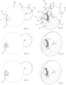
- the support 24 is in the protected position shown in the Figures 2a and 2b .
- the outer surface of the support which extends opposite the socket base 20 relative to the X axis closes the second opening 34.
- the socket base and the optional image acquisition device are therefore isolated from the external environment, and in particular from bad weather.
- the image acquisition device 35 is also advantageously protected from vandalism, and in particular from paint spray.
- the socket base and the optional image acquisition device are well protected.
- the socket base is advantageously at a distance from the outer surface 23 of the cover 30.
- control module activates the motor 36 so as to drive the rotation of the support 24 around the X axis to the acquisition position, in the occurrence a rotation of + 90°.
- the objective of the acquisition device then faces the second opening 34, preferably flush with it, without protruding from it ( Fig. 2c ).
- the control module then triggers the acquisition of at least one image.
- the terminal 12 is arranged such that the image represents a registration plate of a vehicle possibly present on the loading space.
- the control module activates the motor 36 so as to drive the rotation of the support 24 about the X axis to the stowed position, in this case a rotation of -90° or +270°.
- the lens of the acquisition device then no longer faces the second opening 34 and is therefore no longer exposed to the external environment of the housing.
- the control module activates the motor 36 so as to drive the rotation of the support 24 around the X axis to the exposed position ( Figures 2e and 2f ).
- the socket base is then visible through the second opening 34.
- it is flush with the second opening 34 and, more preferably, closes it.
- it does not protrude from the second opening 34, which limits the risk of damage.
- the vehicle can therefore access electrical energy to recharge.
- control module 27 Prior to rotating the support to the exposed position, the control module 27 preferably controls the acquisition of an image in order to identify the vehicle 10. Preferably, it controls the motor 36 until the acquisition device reaches the acquisition position, triggers the acquisition of the image, then controls the motor 36 until the socket reaches the exposed position.
- control module activates the motor 36 again so as to drive the rotation of the support 24 around the X axis to the initial protected position.
- a charging station makes it possible to restrict access to the socket base, whilst ensuring protection of the socket base when it is not in use.
- a charging station makes it possible to acquire an image and transmit it to the central unit via the vehicle, like the charging data. More precisely, the image is sent by the communication network local, preferably via Bluetooth ® , to the vehicle and the latter retransmits it to the control unit 14 when it has access to a mobile telephone network, in particular GSM.
- a mobile telephone network in particular GSM.
- a charging station according to the invention is therefore well suited to being fixed in a private home, with possible access from the street. It is effective even if the station is not subscribed to a mobile telephone network or is in a dead zone and therefore cannot access such a network.
- the detection means may in particular comprise a camera provided with image analysis software capable of detecting, on an image acquired by the camera, a vehicle, and preferably capable of identifying the type of vehicle represented on said acquired image and/or an identifier of said vehicle.
- these means are integrated into at least one charging station according to the invention.
- the indicator can be luminous or audible. It can be particularly adapted to broadcast a voice message, music or an alarm.
- the indication means are integrated into at least one charging terminal according to the invention.
- the indicator is activated only when the vehicle approaches the charging station, for example when it is less than 100 m, or even less than 50 m or less than 10 m from the charging station.
- the locations are not necessarily in a parking lot. They can, for example, be scattered throughout a city.
Landscapes
- Engineering & Computer Science (AREA)
- Power Engineering (AREA)
- Transportation (AREA)
- Mechanical Engineering (AREA)
- Charge And Discharge Circuits For Batteries Or The Like (AREA)
- Electric Propulsion And Braking For Vehicles (AREA)
- Details Of Connecting Devices For Male And Female Coupling (AREA)
- Connector Housings Or Holding Contact Members (AREA)
Claims (12)
- Elektrische Ladestation, welche umfasst:- eine erste Steckdose (20), die dazu bestimmt ist, vom Stromnetz gespeist zu werden und einem Elektrofahrzeug elektrische Energie zu liefern;- ein Gehäuse (22), das dazu bestimmt ist, am Boden oder an einer Wand befestigt zu werden;- eine Halterung (24), an der die erste Steckdose befestigt oder in die sie integriert ist, die bezüglich des Gehäuses um eine Achse X zwischen einer geschützten Position und einer freiliegenden Position beweglich ist, in denen der Zugang zur ersten Steckdose von außerhalb des Gehäuses gesperrt bzw. offen ist;- Mittel zum Antrieb (26) der Halterung zwischen der geschützten und der freiliegenden Position;- ein Steuerungsmodul (27) für die Antriebsmittel;wobei in der Ladestation das Gehäuse (22) eine Öffnung (34) umfasst, die in der geschützten Position verschlossen ist und in der freiliegenden Position einen Zugang zur ersten Steckdose definiert,wobei die Halterung (24) derart ausgebildet ist, dass sie die Öffnung (34) in der freiliegenden Position verschließt, wobei die Halterung (24) derart angeordnet ist, dass sie die Öffnung (34) unabhängig von der Winkelposition der Halterung um die Achse X bezüglich des Gehäuses verschließt,wobei in der Ladestation mindestens ein von der ersten Steckdose (20) verschiedenes Betriebsorgan an der Halterung befestigt ist, wobei die Halterung beweglich ist zwischen- der geschützten Position,- der freiliegenden Position undmindestens einer von der freiliegenden Position verschiedenen Betriebsposition, in welcher der Zugang über die Öffnung (34) zu dem mindestens einen Betriebsorgan offen ist,wobei das Betriebsorgan ausgewählt ist aus einer Bilderfassungsvorrichtung (35), einer Diebstahlsicherung für ein Fahrrad oder Motorrad, einer zweiten Steckdose, die dazu eingerichtet ist, einen elektrischen Strom zu liefern, der von dem der ersten Steckdose (20) verschieden ist, einem Fach, einem Safe, einer Tastatur, einem Bildschirm und einer mit einer Antenne ausgestatteten Kommunikationsbasis.
- Ladestation nach dem vorhergehenden Anspruch, wobei die Halterung (24) am Gehäuse drehbeweglich um eine Achse X zwischen der geschützten und der freiliegenden Position ist.
- Ladestation nach dem vorhergehenden Anspruch, wobei die Drehachse X der Halterung die Achse Y der Öffnung (34) senkrecht schneidet.
- Ladestation nach einem der zwei unmittelbar vorhergehenden Ansprüche, wobei die allgemeine Form der Außenfläche der Halterung (24) die einer Rotationsfläche um die Achse X ist.
- Ladestation nach dem unmittelbar vorhergehenden Anspruch, wobei die allgemeine Form der Außenfläche der Halterung zylindrisch um die Achse X ist oder die Form einer Kugel ist, wobei die Achse X durch den Mittelpunkt der Kugel verläuft.
- Ladestation nach einem der vorhergehenden Ansprüche, wobei das Steuerungsmodul (27) dafür ausgelegt ist, die Antriebsmittel (26) so zu steuern, dass die Halterung ausschließlich zwischen vordefinierten Positionen verlagert wird.
- Ladestation nach einem der unmittelbar vorhergehenden Ansprüche, wobei das Betriebsorgan von dem Steuerungsmodul (27) gesteuert wird.
- Ladestation nach einem der unmittelbar vorhergehenden Ansprüche, wobei das Steuerungsmodul (27) dafür ausgelegt ist, die Antriebsmittel (26) so zu steuern, dass jedes Betriebsorgan zwischen seiner Betriebsposition und mindestens einer Verstauposition verlagert wird, in denen das Betriebsorgan freiliegend bzw. von der äußeren Umgebung des Gehäuses isoliert ist.
- Ladestation nach einem der vorhergehenden Ansprüche, wobei in der geschützten Position die erste Steckdose (20) von der äußeren Umgebung durch einen vor Stößen schützenden Schild (24) getrennt ist, wobei sich der Schild, bezogen auf die Drehachse X der Halterung, wenigstens teilweise gegenüber der ersten Steckdose erstreckt.
- Ladestation nach einem der vorhergehenden Ansprüche, wobei in der geschützten Position die erste Steckdose von der der Umgebung ausgesetzten Außenfläche (23) des Gehäuses um einen Abstand, der größer als 2 cm ist, beabstandet ist, wenn das Gehäuse an der Wand oder am Boden befestigt ist.
- Ladestation nach dem unmittelbar vorhergehenden Anspruch, wobei der Abstand größer als 5 cm ist.
- Vorrichtung, welche mehr als zehn Fahrzeugstellplätze umfasst, wobei jeder Stellplatz mit einer Ladestation nach einem der vorhergehenden Ansprüche versehen ist, wobei die Vorrichtung umfasst:- Mittel zur Erkennung eines Fahrzeugs und- Mittel, um dem Fahrer des Fahrzeugs einen Stellplatz anzuzeigen, wobei die Anzeigemittel mit den Erkennungsmitteln in Kommunikation stehen und eine Software umfassen, die dazu eingerichtet ist,- eine Anforderung der Erkennungsmittel zum Suchen eines Stellplatzes für ein erkanntes Fahrzeug zu empfangen,- dementsprechend einen Stellplatz zu suchen und- nachdem ein Stellplatz gefunden wurde, einen in die Ladestation des gefundenen Stellplatzes integrierten Anzeiger zu steuern.
Applications Claiming Priority (2)
| Application Number | Priority Date | Filing Date | Title |
|---|---|---|---|
| FR1756674A FR3068926B1 (fr) | 2017-07-13 | 2017-07-13 | Borne electrique |
| PCT/EP2018/069104 WO2019012117A1 (fr) | 2017-07-13 | 2018-07-13 | Borne electrique |
Publications (3)
| Publication Number | Publication Date |
|---|---|
| EP3652017A1 EP3652017A1 (de) | 2020-05-20 |
| EP3652017C0 EP3652017C0 (de) | 2024-10-09 |
| EP3652017B1 true EP3652017B1 (de) | 2024-10-09 |
Family
ID=60627713
Family Applications (1)
| Application Number | Title | Priority Date | Filing Date |
|---|---|---|---|
| EP18737637.1A Active EP3652017B1 (de) | 2017-07-13 | 2018-07-13 | Elektrisches endgerät |
Country Status (5)
| Country | Link |
|---|---|
| US (1) | US12103412B2 (de) |
| EP (1) | EP3652017B1 (de) |
| CN (1) | CN111108018B (de) |
| FR (1) | FR3068926B1 (de) |
| WO (1) | WO2019012117A1 (de) |
Cited By (2)
| Publication number | Priority date | Publication date | Assignee | Title |
|---|---|---|---|---|
| US20230353180A1 (en) * | 2022-04-29 | 2023-11-02 | Robert Bosch Gmbh | Communication unit having a fastening device for fastening to a component of an in particular single-track vehicle |
| US12425060B2 (en) * | 2022-04-29 | 2025-09-23 | Robert Bosch Gmbh | Communications unit having a fastening device for fastening to a component of an in particular single-track vehicle |
Families Citing this family (2)
| Publication number | Priority date | Publication date | Assignee | Title |
|---|---|---|---|---|
| FR3115241B1 (fr) * | 2020-10-16 | 2023-09-08 | Stanley Robotics | Système de recharge électrique autonome pour robot mobile extérieur. |
| US12488565B2 (en) * | 2022-07-12 | 2025-12-02 | Rivian Ip Holdings, Llc | Charging systems and methods for detecting and identifying a vehicle and utilizing this information in a charging application |
Citations (1)
| Publication number | Priority date | Publication date | Assignee | Title |
|---|---|---|---|---|
| CN106864302A (zh) * | 2017-04-13 | 2017-06-20 | 深圳市昌圣新能源科技有限公司 | 一种新能源汽车的快速充电装置 |
Family Cites Families (11)
| Publication number | Priority date | Publication date | Assignee | Title |
|---|---|---|---|---|
| CN201199603Y (zh) * | 2008-04-21 | 2009-02-25 | 卢顺接 | 经转动可隐藏的插座装置 |
| WO2010023527A2 (en) * | 2008-08-26 | 2010-03-04 | Panasonic Electric Works Co., Ltd. | Electric vehicle charging cord set |
| PT2362363E (pt) * | 2010-02-18 | 2013-07-09 | Kapsch Trafficcom Ag | Instalação para carregamento eléctrico de veículos |
| AT509513B1 (de) * | 2010-03-05 | 2012-09-15 | Schauer Agrotronic Gmbh | Verfahren zur überwachung pneumatisch betätigbarer membranventile in flüssigfütterungsanlagen |
| ES2425778T3 (es) * | 2011-03-17 | 2013-10-17 | Kapsch Trafficcom Ag | Aparcamiento con sistema de reserva |
| US20130013382A1 (en) * | 2011-07-06 | 2013-01-10 | George William Alexander | System and method for use in delivering energy to an electrically powered vehicle within a parking area |
| EP3160792B1 (de) * | 2014-06-27 | 2018-04-18 | EASYCHARGE.me GmbH | Deckenmontierte ladestation zum aufladen von elektrofahrzeugen |
| US20160352113A1 (en) * | 2015-05-29 | 2016-12-01 | GM Global Technology Operations LLC | Electric vehicle charging station |
| US9662995B2 (en) | 2015-07-06 | 2017-05-30 | Hon Hai Precision Industry Co., Ltd. | Battery charging system and apparatus and method for electric vehicle |
| NL2015564B1 (en) * | 2015-10-05 | 2017-05-17 | Brainwave B V | Underground power supply system, in particular an underground vehicle charging station and a method to charge an electric vehicle. |
| CN205303795U (zh) * | 2016-01-21 | 2016-06-08 | 潘祥萌 | 一种可转换插座结构 |
-
2017
- 2017-07-13 FR FR1756674A patent/FR3068926B1/fr active Active
-
2018
- 2018-07-13 EP EP18737637.1A patent/EP3652017B1/de active Active
- 2018-07-13 CN CN201880059832.7A patent/CN111108018B/zh active Active
- 2018-07-13 WO PCT/EP2018/069104 patent/WO2019012117A1/fr not_active Ceased
- 2018-07-13 US US16/629,797 patent/US12103412B2/en active Active
Patent Citations (1)
| Publication number | Priority date | Publication date | Assignee | Title |
|---|---|---|---|---|
| CN106864302A (zh) * | 2017-04-13 | 2017-06-20 | 深圳市昌圣新能源科技有限公司 | 一种新能源汽车的快速充电装置 |
Cited By (2)
| Publication number | Priority date | Publication date | Assignee | Title |
|---|---|---|---|---|
| US20230353180A1 (en) * | 2022-04-29 | 2023-11-02 | Robert Bosch Gmbh | Communication unit having a fastening device for fastening to a component of an in particular single-track vehicle |
| US12425060B2 (en) * | 2022-04-29 | 2025-09-23 | Robert Bosch Gmbh | Communications unit having a fastening device for fastening to a component of an in particular single-track vehicle |
Also Published As
| Publication number | Publication date |
|---|---|
| FR3068926A1 (fr) | 2019-01-18 |
| FR3068926B1 (fr) | 2021-01-29 |
| EP3652017A1 (de) | 2020-05-20 |
| US12103412B2 (en) | 2024-10-01 |
| CN111108018A (zh) | 2020-05-05 |
| EP3652017C0 (de) | 2024-10-09 |
| WO2019012117A1 (fr) | 2019-01-17 |
| US20210078420A1 (en) | 2021-03-18 |
| CN111108018B (zh) | 2024-06-07 |
Similar Documents
| Publication | Publication Date | Title |
|---|---|---|
| EP3652017B1 (de) | Elektrisches endgerät | |
| EP2727091B1 (de) | Verfahren und system zur verwaltung eines aufladeraums für ein fahrzeug, insbesondere ein selbstbedienungselektrofahrzeug | |
| WO2015145067A1 (fr) | Parking souterrain pour vehicules electriques | |
| EP2781397B1 (de) | Automatisches System zur Speicherung von Zyklen, und Batterie für ein solches System | |
| EP2727212A1 (de) | Verfahren und system zum verbinden und lösen eines elektrofahrzeugs mit bzw. von einer ladestation | |
| EP3652711B1 (de) | Verfahren zur verwendung elektrischer punkte | |
| FR2978414A1 (fr) | Systeme automatique de stockage de cycles et cycle pour un tel systeme. | |
| EP2727087B1 (de) | Verfahren zur überprüfung der anwendung der funktionen eines bereitgestellten fahrzeugs | |
| EP2727213B1 (de) | Ladeterminal für ein elektrisches fahrzeug sowie station und system mit einem solchen terminal | |
| WO2016128472A1 (fr) | Présentoir semi-automatique de bouteilles de gaz et procédé associé | |
| EP3888227B1 (de) | Verfahren zum induktiven aufladen einer batterie eines geparkten fahrzeugs unter verwendung eines relativ zu einer referenz bewegbaren gehäuses | |
| FR3108286A1 (fr) | Système et dispositif d’affichage d’informations pour véhicule basé sur des profils d’affichage | |
| FR3153306A1 (fr) | Procédé pour la mise en service opérationnel d’un véhicule partagé. | |
| FR3082639A1 (fr) | Procede et dispositif de detection de requete de diagnostic frauduleuse sur un vehicule. | |
| FR2837764A1 (fr) | Procede et dispositif de protection contre le vol pour un vehicule | |
| FR3084025A1 (fr) | Boitier mobile autonome a eclairement de son environnement, pour recharger par induction une batterie de vehicule | |
| FR3152252A1 (fr) | Procede de depannage de rechargement de vehicules automobiles electriques ou hybrides | |
| FR3147230A1 (fr) | Procede de parametrage et d’affichage du temps de charge restant d’un vehicule electrique ou hybride mettant en œuvre un qr code | |
| EP4548120A2 (de) | Verfahren zur steuerung eines fernsteuerbaren elements mit einem oder mehreren beweglichen objekten | |
| EP1603081A1 (de) | Verfahren und System zum Fahrzeugflottenmanagement | |
| FR3101029A1 (fr) | Dispositif d'affichage pour vehicule | |
| WO2013001257A1 (fr) | Procede, systeme et installation de detection d'une utilisation frauduleuse d'un vehicule | |
| FR2961752A1 (fr) | Dispositif de controle d'ouverture d'un toit ouvrant de vehicule automobile par une personne situee a l'exterieur | |
| FR3018374A1 (fr) | Dispositif d'identification rfid bf sans contact securise et simplifie destine a remplacer les cles de tout types de vehicules |
Legal Events
| Date | Code | Title | Description |
|---|---|---|---|
| STAA | Information on the status of an ep patent application or granted ep patent |
Free format text: STATUS: UNKNOWN |
|
| STAA | Information on the status of an ep patent application or granted ep patent |
Free format text: STATUS: THE INTERNATIONAL PUBLICATION HAS BEEN MADE |
|
| PUAI | Public reference made under article 153(3) epc to a published international application that has entered the european phase |
Free format text: ORIGINAL CODE: 0009012 |
|
| STAA | Information on the status of an ep patent application or granted ep patent |
Free format text: STATUS: REQUEST FOR EXAMINATION WAS MADE |
|
| 17P | Request for examination filed |
Effective date: 20200213 |
|
| AK | Designated contracting states |
Kind code of ref document: A1 Designated state(s): AL AT BE BG CH CY CZ DE DK EE ES FI FR GB GR HR HU IE IS IT LI LT LU LV MC MK MT NL NO PL PT RO RS SE SI SK SM TR |
|
| AX | Request for extension of the european patent |
Extension state: BA ME |
|
| DAV | Request for validation of the european patent (deleted) | ||
| DAX | Request for extension of the european patent (deleted) | ||
| STAA | Information on the status of an ep patent application or granted ep patent |
Free format text: STATUS: EXAMINATION IS IN PROGRESS |
|
| 17Q | First examination report despatched |
Effective date: 20211115 |
|
| GRAP | Despatch of communication of intention to grant a patent |
Free format text: ORIGINAL CODE: EPIDOSNIGR1 |
|
| STAA | Information on the status of an ep patent application or granted ep patent |
Free format text: STATUS: GRANT OF PATENT IS INTENDED |
|
| INTG | Intention to grant announced |
Effective date: 20230609 |
|
| GRAJ | Information related to disapproval of communication of intention to grant by the applicant or resumption of examination proceedings by the epo deleted |
Free format text: ORIGINAL CODE: EPIDOSDIGR1 |
|
| STAA | Information on the status of an ep patent application or granted ep patent |
Free format text: STATUS: EXAMINATION IS IN PROGRESS |
|
| INTC | Intention to grant announced (deleted) | ||
| GRAP | Despatch of communication of intention to grant a patent |
Free format text: ORIGINAL CODE: EPIDOSNIGR1 |
|
| STAA | Information on the status of an ep patent application or granted ep patent |
Free format text: STATUS: GRANT OF PATENT IS INTENDED |
|
| INTG | Intention to grant announced |
Effective date: 20231208 |
|
| GRAJ | Information related to disapproval of communication of intention to grant by the applicant or resumption of examination proceedings by the epo deleted |
Free format text: ORIGINAL CODE: EPIDOSDIGR1 |
|
| STAA | Information on the status of an ep patent application or granted ep patent |
Free format text: STATUS: EXAMINATION IS IN PROGRESS |
|
| INTC | Intention to grant announced (deleted) | ||
| GRAP | Despatch of communication of intention to grant a patent |
Free format text: ORIGINAL CODE: EPIDOSNIGR1 |
|
| STAA | Information on the status of an ep patent application or granted ep patent |
Free format text: STATUS: GRANT OF PATENT IS INTENDED |
|
| INTG | Intention to grant announced |
Effective date: 20240426 |
|
| GRAS | Grant fee paid |
Free format text: ORIGINAL CODE: EPIDOSNIGR3 |
|
| GRAA | (expected) grant |
Free format text: ORIGINAL CODE: 0009210 |
|
| STAA | Information on the status of an ep patent application or granted ep patent |
Free format text: STATUS: THE PATENT HAS BEEN GRANTED |
|
| AK | Designated contracting states |
Kind code of ref document: B1 Designated state(s): AL AT BE BG CH CY CZ DE DK EE ES FI FR GB GR HR HU IE IS IT LI LT LU LV MC MK MT NL NO PL PT RO RS SE SI SK SM TR |
|
| REG | Reference to a national code |
Ref country code: CH Ref legal event code: EP |
|
| REG | Reference to a national code |
Ref country code: DE Ref legal event code: R096 Ref document number: 602018075188 Country of ref document: DE |
|
| REG | Reference to a national code |
Ref country code: IE Ref legal event code: FG4D Free format text: LANGUAGE OF EP DOCUMENT: FRENCH |
|
| U01 | Request for unitary effect filed |
Effective date: 20241022 |
|
| U07 | Unitary effect registered |
Designated state(s): AT BE BG DE DK EE FI FR IT LT LU LV MT NL PT RO SE SI Effective date: 20241105 |
|
| PG25 | Lapsed in a contracting state [announced via postgrant information from national office to epo] |
Ref country code: IS Free format text: LAPSE BECAUSE OF FAILURE TO SUBMIT A TRANSLATION OF THE DESCRIPTION OR TO PAY THE FEE WITHIN THE PRESCRIBED TIME-LIMIT Effective date: 20250209 Ref country code: HR Free format text: LAPSE BECAUSE OF FAILURE TO SUBMIT A TRANSLATION OF THE DESCRIPTION OR TO PAY THE FEE WITHIN THE PRESCRIBED TIME-LIMIT Effective date: 20241009 |
|
| PG25 | Lapsed in a contracting state [announced via postgrant information from national office to epo] |
Ref country code: ES Free format text: LAPSE BECAUSE OF FAILURE TO SUBMIT A TRANSLATION OF THE DESCRIPTION OR TO PAY THE FEE WITHIN THE PRESCRIBED TIME-LIMIT Effective date: 20241009 |
|
| PG25 | Lapsed in a contracting state [announced via postgrant information from national office to epo] |
Ref country code: NO Free format text: LAPSE BECAUSE OF FAILURE TO SUBMIT A TRANSLATION OF THE DESCRIPTION OR TO PAY THE FEE WITHIN THE PRESCRIBED TIME-LIMIT Effective date: 20250109 |
|
| PG25 | Lapsed in a contracting state [announced via postgrant information from national office to epo] |
Ref country code: GR Free format text: LAPSE BECAUSE OF FAILURE TO SUBMIT A TRANSLATION OF THE DESCRIPTION OR TO PAY THE FEE WITHIN THE PRESCRIBED TIME-LIMIT Effective date: 20250110 |
|
| PG25 | Lapsed in a contracting state [announced via postgrant information from national office to epo] |
Ref country code: PL Free format text: LAPSE BECAUSE OF FAILURE TO SUBMIT A TRANSLATION OF THE DESCRIPTION OR TO PAY THE FEE WITHIN THE PRESCRIBED TIME-LIMIT Effective date: 20241009 |
|
| PG25 | Lapsed in a contracting state [announced via postgrant information from national office to epo] |
Ref country code: RS Free format text: LAPSE BECAUSE OF FAILURE TO SUBMIT A TRANSLATION OF THE DESCRIPTION OR TO PAY THE FEE WITHIN THE PRESCRIBED TIME-LIMIT Effective date: 20250109 |
|
| PG25 | Lapsed in a contracting state [announced via postgrant information from national office to epo] |
Ref country code: SM Free format text: LAPSE BECAUSE OF FAILURE TO SUBMIT A TRANSLATION OF THE DESCRIPTION OR TO PAY THE FEE WITHIN THE PRESCRIBED TIME-LIMIT Effective date: 20241009 |
|
| PG25 | Lapsed in a contracting state [announced via postgrant information from national office to epo] |
Ref country code: SK Free format text: LAPSE BECAUSE OF FAILURE TO SUBMIT A TRANSLATION OF THE DESCRIPTION OR TO PAY THE FEE WITHIN THE PRESCRIBED TIME-LIMIT Effective date: 20241009 |
|
| PG25 | Lapsed in a contracting state [announced via postgrant information from national office to epo] |
Ref country code: CZ Free format text: LAPSE BECAUSE OF FAILURE TO SUBMIT A TRANSLATION OF THE DESCRIPTION OR TO PAY THE FEE WITHIN THE PRESCRIBED TIME-LIMIT Effective date: 20241009 |
|
| PLBE | No opposition filed within time limit |
Free format text: ORIGINAL CODE: 0009261 |
|
| STAA | Information on the status of an ep patent application or granted ep patent |
Free format text: STATUS: NO OPPOSITION FILED WITHIN TIME LIMIT |
|
| U20 | Renewal fee for the european patent with unitary effect paid |
Year of fee payment: 8 Effective date: 20250728 |
|
| 26N | No opposition filed |
Effective date: 20250710 |
|
| U1N | Appointed representative for the unitary patent procedure changed after the registration of the unitary effect |
Representative=s name: IPSILON; FR |
|
| REG | Reference to a national code |
Ref country code: CH Ref legal event code: H13 Free format text: ST27 STATUS EVENT CODE: U-0-0-H10-H13 (AS PROVIDED BY THE NATIONAL OFFICE) Effective date: 20260224 |