EP3652012B1 - Flüssigkeitsbehälter für ein kraftfahrzeug - Google Patents
Flüssigkeitsbehälter für ein kraftfahrzeug Download PDFInfo
- Publication number
- EP3652012B1 EP3652012B1 EP18742739.8A EP18742739A EP3652012B1 EP 3652012 B1 EP3652012 B1 EP 3652012B1 EP 18742739 A EP18742739 A EP 18742739A EP 3652012 B1 EP3652012 B1 EP 3652012B1
- Authority
- EP
- European Patent Office
- Prior art keywords
- pump
- heating element
- recess
- liquid container
- container according
- Prior art date
- Legal status (The legal status is an assumption and is not a legal conclusion. Google has not performed a legal analysis and makes no representation as to the accuracy of the status listed.)
- Active
Links
Images
Classifications
-
- B—PERFORMING OPERATIONS; TRANSPORTING
- B60—VEHICLES IN GENERAL
- B60K—ARRANGEMENT OR MOUNTING OF PROPULSION UNITS OR OF TRANSMISSIONS IN VEHICLES; ARRANGEMENT OR MOUNTING OF PLURAL DIVERSE PRIME-MOVERS IN VEHICLES; AUXILIARY DRIVES FOR VEHICLES; INSTRUMENTATION OR DASHBOARDS FOR VEHICLES; ARRANGEMENTS IN CONNECTION WITH COOLING, AIR INTAKE, GAS EXHAUST OR FUEL SUPPLY OF PROPULSION UNITS IN VEHICLES
- B60K13/00—Arrangement in connection with combustion air intake or gas exhaust of propulsion units
- B60K13/04—Arrangement in connection with combustion air intake or gas exhaust of propulsion units concerning exhaust
-
- F—MECHANICAL ENGINEERING; LIGHTING; HEATING; WEAPONS; BLASTING
- F01—MACHINES OR ENGINES IN GENERAL; ENGINE PLANTS IN GENERAL; STEAM ENGINES
- F01N—GAS-FLOW SILENCERS OR EXHAUST APPARATUS FOR MACHINES OR ENGINES IN GENERAL; GAS-FLOW SILENCERS OR EXHAUST APPARATUS FOR INTERNAL-COMBUSTION ENGINES
- F01N3/00—Exhaust or silencing apparatus having means for purifying, rendering innocuous, or otherwise treating exhaust
- F01N3/08—Exhaust or silencing apparatus having means for purifying, rendering innocuous, or otherwise treating exhaust for rendering innocuous
- F01N3/10—Exhaust or silencing apparatus having means for purifying, rendering innocuous, or otherwise treating exhaust for rendering innocuous by thermal or catalytic conversion of noxious components of exhaust
- F01N3/18—Exhaust or silencing apparatus having means for purifying, rendering innocuous, or otherwise treating exhaust for rendering innocuous by thermal or catalytic conversion of noxious components of exhaust characterised by methods of operation; Control
- F01N3/20—Exhaust or silencing apparatus having means for purifying, rendering innocuous, or otherwise treating exhaust for rendering innocuous by thermal or catalytic conversion of noxious components of exhaust characterised by methods of operation; Control specially adapted for catalytic conversion
- F01N3/206—Adding periodically or continuously substances to exhaust gases for promoting purification, e.g. catalytic material in liquid form, NOx reducing agents
- F01N3/2066—Selective catalytic reduction [SCR]
-
- B—PERFORMING OPERATIONS; TRANSPORTING
- B60—VEHICLES IN GENERAL
- B60K—ARRANGEMENT OR MOUNTING OF PROPULSION UNITS OR OF TRANSMISSIONS IN VEHICLES; ARRANGEMENT OR MOUNTING OF PLURAL DIVERSE PRIME-MOVERS IN VEHICLES; AUXILIARY DRIVES FOR VEHICLES; INSTRUMENTATION OR DASHBOARDS FOR VEHICLES; ARRANGEMENTS IN CONNECTION WITH COOLING, AIR INTAKE, GAS EXHAUST OR FUEL SUPPLY OF PROPULSION UNITS IN VEHICLES
- B60K15/00—Arrangement in connection with fuel supply of combustion engines or other fuel consuming energy converters, e.g. fuel cells; Mounting or construction of fuel tanks
- B60K15/03—Fuel tanks
- B60K2015/03105—Fuel tanks with supplementary interior tanks inside the fuel tank
-
- B—PERFORMING OPERATIONS; TRANSPORTING
- B60—VEHICLES IN GENERAL
- B60K—ARRANGEMENT OR MOUNTING OF PROPULSION UNITS OR OF TRANSMISSIONS IN VEHICLES; ARRANGEMENT OR MOUNTING OF PLURAL DIVERSE PRIME-MOVERS IN VEHICLES; AUXILIARY DRIVES FOR VEHICLES; INSTRUMENTATION OR DASHBOARDS FOR VEHICLES; ARRANGEMENTS IN CONNECTION WITH COOLING, AIR INTAKE, GAS EXHAUST OR FUEL SUPPLY OF PROPULSION UNITS IN VEHICLES
- B60K15/00—Arrangement in connection with fuel supply of combustion engines or other fuel consuming energy converters, e.g. fuel cells; Mounting or construction of fuel tanks
- B60K15/03—Fuel tanks
- B60K2015/03111—Swirl pots
-
- B—PERFORMING OPERATIONS; TRANSPORTING
- B60—VEHICLES IN GENERAL
- B60K—ARRANGEMENT OR MOUNTING OF PROPULSION UNITS OR OF TRANSMISSIONS IN VEHICLES; ARRANGEMENT OR MOUNTING OF PLURAL DIVERSE PRIME-MOVERS IN VEHICLES; AUXILIARY DRIVES FOR VEHICLES; INSTRUMENTATION OR DASHBOARDS FOR VEHICLES; ARRANGEMENTS IN CONNECTION WITH COOLING, AIR INTAKE, GAS EXHAUST OR FUEL SUPPLY OF PROPULSION UNITS IN VEHICLES
- B60K15/00—Arrangement in connection with fuel supply of combustion engines or other fuel consuming energy converters, e.g. fuel cells; Mounting or construction of fuel tanks
- B60K15/03—Fuel tanks
- B60K2015/03243—Fuel tanks characterised by special pumps, the mounting thereof
- B60K2015/0325—Jet pumps
-
- B—PERFORMING OPERATIONS; TRANSPORTING
- B60—VEHICLES IN GENERAL
- B60K—ARRANGEMENT OR MOUNTING OF PROPULSION UNITS OR OF TRANSMISSIONS IN VEHICLES; ARRANGEMENT OR MOUNTING OF PLURAL DIVERSE PRIME-MOVERS IN VEHICLES; AUXILIARY DRIVES FOR VEHICLES; INSTRUMENTATION OR DASHBOARDS FOR VEHICLES; ARRANGEMENTS IN CONNECTION WITH COOLING, AIR INTAKE, GAS EXHAUST OR FUEL SUPPLY OF PROPULSION UNITS IN VEHICLES
- B60K15/00—Arrangement in connection with fuel supply of combustion engines or other fuel consuming energy converters, e.g. fuel cells; Mounting or construction of fuel tanks
- B60K15/03—Fuel tanks
- B60K2015/03328—Arrangements or special measures related to fuel tanks or fuel handling
- B60K2015/03348—Arrangements or special measures related to fuel tanks or fuel handling for supplying additives to fuel
-
- B—PERFORMING OPERATIONS; TRANSPORTING
- B60—VEHICLES IN GENERAL
- B60K—ARRANGEMENT OR MOUNTING OF PROPULSION UNITS OR OF TRANSMISSIONS IN VEHICLES; ARRANGEMENT OR MOUNTING OF PLURAL DIVERSE PRIME-MOVERS IN VEHICLES; AUXILIARY DRIVES FOR VEHICLES; INSTRUMENTATION OR DASHBOARDS FOR VEHICLES; ARRANGEMENTS IN CONNECTION WITH COOLING, AIR INTAKE, GAS EXHAUST OR FUEL SUPPLY OF PROPULSION UNITS IN VEHICLES
- B60K15/00—Arrangement in connection with fuel supply of combustion engines or other fuel consuming energy converters, e.g. fuel cells; Mounting or construction of fuel tanks
- B60K15/03—Fuel tanks
- B60K2015/03328—Arrangements or special measures related to fuel tanks or fuel handling
- B60K2015/03427—Arrangements or special measures related to fuel tanks or fuel handling for heating fuel, e.g. to avoiding freezing
-
- F—MECHANICAL ENGINEERING; LIGHTING; HEATING; WEAPONS; BLASTING
- F01—MACHINES OR ENGINES IN GENERAL; ENGINE PLANTS IN GENERAL; STEAM ENGINES
- F01N—GAS-FLOW SILENCERS OR EXHAUST APPARATUS FOR MACHINES OR ENGINES IN GENERAL; GAS-FLOW SILENCERS OR EXHAUST APPARATUS FOR INTERNAL-COMBUSTION ENGINES
- F01N2610/00—Adding substances to exhaust gases
- F01N2610/02—Adding substances to exhaust gases the substance being ammonia or urea
-
- F—MECHANICAL ENGINEERING; LIGHTING; HEATING; WEAPONS; BLASTING
- F01—MACHINES OR ENGINES IN GENERAL; ENGINE PLANTS IN GENERAL; STEAM ENGINES
- F01N—GAS-FLOW SILENCERS OR EXHAUST APPARATUS FOR MACHINES OR ENGINES IN GENERAL; GAS-FLOW SILENCERS OR EXHAUST APPARATUS FOR INTERNAL-COMBUSTION ENGINES
- F01N2610/00—Adding substances to exhaust gases
- F01N2610/14—Arrangements for the supply of substances, e.g. conduits
- F01N2610/1406—Storage means for substances, e.g. tanks or reservoirs
-
- Y—GENERAL TAGGING OF NEW TECHNOLOGICAL DEVELOPMENTS; GENERAL TAGGING OF CROSS-SECTIONAL TECHNOLOGIES SPANNING OVER SEVERAL SECTIONS OF THE IPC; TECHNICAL SUBJECTS COVERED BY FORMER USPC CROSS-REFERENCE ART COLLECTIONS [XRACs] AND DIGESTS
- Y02—TECHNOLOGIES OR APPLICATIONS FOR MITIGATION OR ADAPTATION AGAINST CLIMATE CHANGE
- Y02A—TECHNOLOGIES FOR ADAPTATION TO CLIMATE CHANGE
- Y02A50/00—TECHNOLOGIES FOR ADAPTATION TO CLIMATE CHANGE in human health protection, e.g. against extreme weather
- Y02A50/20—Air quality improvement or preservation, e.g. vehicle emission control or emission reduction by using catalytic converters
-
- Y—GENERAL TAGGING OF NEW TECHNOLOGICAL DEVELOPMENTS; GENERAL TAGGING OF CROSS-SECTIONAL TECHNOLOGIES SPANNING OVER SEVERAL SECTIONS OF THE IPC; TECHNICAL SUBJECTS COVERED BY FORMER USPC CROSS-REFERENCE ART COLLECTIONS [XRACs] AND DIGESTS
- Y02—TECHNOLOGIES OR APPLICATIONS FOR MITIGATION OR ADAPTATION AGAINST CLIMATE CHANGE
- Y02T—CLIMATE CHANGE MITIGATION TECHNOLOGIES RELATED TO TRANSPORTATION
- Y02T10/00—Road transport of goods or passengers
- Y02T10/10—Internal combustion engine [ICE] based vehicles
- Y02T10/12—Improving ICE efficiencies
Definitions
- the invention relates to a liquid container for a motor vehicle, with a storage volume for storing a liquid, with a surge pot, which is arranged within the storage volume, and with a pump.
- aqueous operating fluids are used, for example, to increase engine performance or to reduce pollutant emissions.
- systems for water injection are known.
- the aqueous operating fluids carried in a fluid container can freeze at correspondingly low outside temperatures. In such a case, rapid thawing of the aqueous operating fluid is necessary in order to enable it to be conveyed and to supply the corresponding systems with the fluid.
- a surge pot in a storage volume that delimits a secondary volume in which defrosting can take place quickly and in a targeted manner in order to achieve rapid operational readiness of the respective system.
- the surge pot is usually assigned a pump module that is connected to the surge pot via lines.
- the liquid is accordingly conveyed out of the surge pot and supplied to injection nozzles, for example.
- revealed DE 10 2005 000 730 A1 discloses a two-part fuel tank.
- the disadvantage here is that the surge pot together with the pump module results in a volume loss of up to 10% of the storage volume.
- the pump module must be heated by a separate heater. Connecting lines between the pump and the surge pot or the pump and the liquid container must also be heated separately.
- the invention is based on the technical problem of specifying a liquid container for a motor vehicle that does not have the disadvantages described above or at least to a lesser extent, and in particular brings with it an improved utilization of the storage volume and reduced system complexity .
- a liquid container for a motor vehicle is specified, with a storage volume for storing a liquid, with a surge pot, which is arranged within the storage volume, and with a pump.
- the surge pot has an indentation for receiving a pump and the pump sits at least in sections in the indentation.
- the pump is accordingly framed by the surge pot at least in sections on the circumferential side.
- the integration of the pump into the surge pot at least in sections also has the advantage that a heat input in the area of the surge pot is also used to heat the pump can be.
- a heating device set up to heat the surge pot can also heat the pump, so that a separate heater for the pump can be dispensed with.
- the integration of the pump into the surge pot, at least in sections, also has the advantage that connecting lines and the heating devices between the pump and the surge pot that are also required for this can be dispensed with.
- the indentation can be an indentation that has been produced during deep drawing or injection molding of the surge pot.
- the pump can be encompassed at least in sections by an outer surface of a wall of the surge pot, with one or more through openings being provided in the wall of the surge pot in order to convey liquid from or into a secondary volume formed by the surge pot.
- the pump is therefore fluidly connected to the secondary volume via the through openings and possibly interposed valves or line sections.
- Valves or line sections can be integrated at least in sections, in particular completely, into an envelope of the surge pot.
- the pump sits completely in the indentation. In this way, a particularly compact arrangement of the pump can be realized.
- the indentation can be provided in a base of the surge pot.
- Such an arrangement can be implemented in a particularly simple manner in terms of production engineering and enables the pump to be oriented properly within the liquid container.
- a heating element is provided or several heating elements are provided. At least one heating element is set up to heat a wall delimiting the indentation and / or to heat the pump. Such a heating element accelerates the readiness for use of a system coupled to the liquid container in a motor vehicle insofar as the liquid to be stored is frozen or the viscosity of the liquid is to be reduced.
- At least one heating element can be arranged in such a way that it both heats a wall delimiting the indentation and also causes the pump to be heated. This means that there is no need for an additional heating element for the pump.
- At least one heating element can be arranged on the wall delimiting the indentation.
- a heating element can be glued to the wall. A flexible and inexpensive arrangement of one heating element or several heating elements can thus be achieved.
- At least one heating element is partially or completely integrated into the wall delimiting the indentation. In this way, damage to the heating element due to corrosion or other environmental influences can be avoided.
- At least one heating element can be designed to heat the wall delimiting the indentation over a large area on both sides. In this way, heat can be introduced both into a secondary volume delimited by the surge pot and in the direction of the pump.
- At least one heating element is an integral part of the wall delimiting the indentation is, wherein the heating element has a polymer that has a positive temperature coefficient, and wherein electrodes are connected to the polymer, which are set up to transmit an electrical current for heating the polymer, in particular that the heating element is completely surrounded by a plastic wall .
- the heating element can be a PTC heating element.
- the use of a PTC heating element has the advantage that, due to the temperature behavior of the polymer, there is no need for a control to avoid overheating. Damage to the heating device due to overheating can thus be avoided even when the surge pot is low, since the PTC heating device switches off automatically due to the resistance of the polymer, which increases sharply with increasing temperature.
- the heating element can consist of a polymer, the polymer having a positive temperature coefficient.
- the polymer of the heating element can in particular be heated with the aid of the electrodes, the electrodes being able to be coupled or coupled to an electrical energy source, in particular to a voltage source, for introducing a heating power.
- the polymer can be a material that is solid or pasty at room temperature.
- the polymer can be a thermoplastic material.
- the polymer can be a polyethylene (PE).
- the polymer can contain additives which effect or increase the electrical conductivity of the polymer.
- the polymer can have carbon black as an additive.
- the additive can be a non-metallic additive.
- the electrodes can have an essentially linear shape, that is, they can be narrow and elongated, or they can be plate-shaped. In particular, the plate-like shape offers the advantage that heating power can be introduced over a large area.
- the electrodes can be set up to initiate a current flow transversely to a wall surface of the surge pot.
- electrodes can be provided which are set up to initiate a current flow perpendicular to a wall surface of the surge pot.
- the electrodes can be set up to initiate a current flow along a wall surface of the surge pot.
- electrodes can be provided which are set up to initiate a current flow parallel to a wall surface of the surge pot.
- Electrodes assigned to a heating element can be linear.
- Electrodes assigned to a heating element can be plate-shaped.
- linear electrodes or plate-shaped electrodes can be assigned to a first heating element.
- Line-shaped electrodes or plate-shaped electrodes can be assigned to an additional, second heating element.
- the first heating element can be arranged in a side wall of the surge pot.
- the second heating element can be arranged in a bottom of the surge pot.
- the electrodes can be at least partially covered by a plastic wall of the surge pot.
- the heating element can have one or more ceramic PTC elements, so-called "PTC stones", which can be completely or partially embedded in a wall of the surge pot.
- PTC stones can sit on one or more metallic heat conductors, e.g. made of aluminum, in order to distribute the very high local heat density of the PTC bricks during heating.
- the metallic heat conducting bodies can also be completely or partially embedded in the wall of the surge pot.
- a thermally conductive potting compound is provided between the pump and the surge pot, the potting compound connecting the pump and the surge pot in the area of the indentation without any gaps, at least in sections.
- the potting compound can be, for example, a silicone elastomer that has a hardness of 30-60 Shore (A) and a thermal conductivity of 1.5-3 W / (m * K).
- the pump can be connected to a metering line, the metering line running at least in sections between the pump and the surge pot in the region of the indentation.
- the heating elements assigned to the pump and / or the surge pot can also be set up to heat the metering line.
- a metering line running between the pump and the surge pot is supplied by a the surge pot and the pump connecting potting compound is enclosed.
- a jet pump In order to achieve a conveyance of liquid from the storage volume into the surge pot in a simple manner, a jet pump can be provided.
- the pump is coupled to the jet pump to generate a propulsion jet.
- a valve can be arranged at a pump outlet of the pump, which valve is set up to prevent the entry of liquid when the pump is at a standstill.
- the valve can be designed to prevent liquid from penetrating into the pump from a secondary volume defined by the surge pot when the pump is at a standstill.
- a secondary volume is spoken of in the present case, then this is a volume delimited by an inside of a wall of the surge pot that faces away from an outside of the wall assigned to the pump.
- the surge pot is arranged below a maximum fill level of the liquid in the storage volume, there is the possibility that the surge pot is completely surrounded by an ice mass or is spanned by an ice surface when the liquid freezes. In such a case, there is a risk that by switching on the pump and removing liquid from the tank, a negative pressure is generated below the ice surface or a cavity is formed within a closed block of ice. After a certain start-up time, it is no longer possible to pump liquid because the suction area of the pump cannot be ventilated.
- a pump inlet of the pump can have a pipeline which, starting from an intake section, at least in sections above a maximum fill level of the storage volume runs. As far as heated liquid flows through this pipeline, ice adjoining the pipeline on the circumference is melted so that ventilation of the suction area can be achieved.
- a suction opening can be provided for conveying liquid from the storage volume into the secondary volume of the surge pot, to which a mushroom head valve is assigned.
- the mushroom head valve allows the surge pot to be filled for the first time when the liquid container is filled for the first time.
- the mushroom head valve ensures that the surge pot is protected against idling, especially in cases in which no energy is supplied to the pump and the pump is at a standstill.
- a suction opening for conveying liquid from the storage volume into the secondary volume of the surge pot can be spaced from the surge pot.
- a suction opening can be integrated into a side wall or a bottom of the surge top.
- a suction line and a possibly required heating device for heating such a suction line can be dispensed with.
- a pump inlet of the pump can have a filter which is arranged in a falling pipe section of the pump inlet. In this way it can be achieved that the filter can be drained by emptying the pump. It can thus be avoided that liquid collects in the filter, which, for example, may have to be thawed before starting a water injection system and thus delaying the system start.
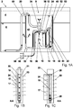
- Figure 1A shows a liquid container 2 for a motor vehicle.
- the liquid container 2 has a storage volume 4 for storing a liquid 6.
- a surge pot 8 is arranged within the storage volume 4.
- a pump 10 is arranged within the storage volume 4.
- the surge pot 8 has an indentation 12 for receiving the pump 10.
- the pump 10 is seated completely in the indentation 12.
- the indentation 12 has been produced here as an indentation in an injection molding process.
- the indentation 12 is provided in a base 14 of the surge pot 8. Heating elements 16, 18, 20, 22 are provided.
- the heating elements 16 and 18 are designed to heat a wall 24 delimiting the indentation 12 and to heat the pump 10.
- the heating elements 16, 18 are an integral part of the wall 24 of the surge pot 8 that delimits the indentation 12.
- the heating elements 20, 22 are completely surrounded by the wall 24 of the surge pot 8 in an analogous manner.
- the heating element 20 is completely enclosed by a plastic 13 of the wall 24.
- the heating element 20 accordingly has no direct contact with the liquid 6.
- the heating element 20 is in the present case a PTC heating element 20.
- the heating element 20 in the present case consists of a polymer 11, the polymer 11 having a positive temperature coefficient. This means that the electrical resistance of the polymer 11 increases as the temperature rises.
- Electrodes 19, 21, 26, 28 are provided, which are connected to the polymer 11.
- the polymer 11 is solid at room temperature. According to alternative configurations, however, it can be provided that the polymer is a material which is pasty at room temperature and is embedded in the wall 24.
- the polymer 11 is mixed with additives in order to effect or increase the electrical conductivity of the polymer.
- the electrodes 26, 28 are set up for introducing a current flow 15 along a wall surface 17 of the surge pot 8.
- the current flow 15 is oriented in particular parallel to the wall surface 17 of the surge pot 8.
- the electrodes 19, 21 are set up for introducing the current flow 15 transversely to the wall surface 17 of the surge pot 8.
- the current flow 15 is in particular oriented perpendicular to the wall surface 17 of the surge pot 8.
- the electrodes 19, 21 according to Figure 1C plate-shaped electrodes 19, 21 and ensure an areal distribution of heat 23.
- substantially linear electrodes 26, 28 are provided.
- a thermally conductive potting compound 30 is provided between the pump and the surge pot 8.
- the potting compound 30 connects the pump 10 and the surge pot 8 in the area of the indentation 12 without a gap.
- the pump 10 is connected to a metering line 32.
- the metering line 32 extends in the area of the indentation 12 between the pump 10 and the surge pot 8.
- the metering line 32 is embedded in the potting compound 30 or enclosed by the potting compound 30.
- a jet pump 34 is provided for conveying liquid 6 from the storage volume 4 into the surge pot 8.
- the pump 10 is coupled to the jet pump 34 for generating a propulsion jet.
- a valve 38 is arranged at a pump outlet 36 of the pump 10.
- the valve 38 is set up to prevent liquid from entering when the pump 10 is at a standstill.
- the valve 38 prevents the pump from overflowing after the pump has been emptied. It is prevented that liquid 6 can penetrate into the pump 10 from a secondary volume 40 delimited by the surge pot 8.
- a pump inlet 42 of the pump 10 has a pipeline 44.
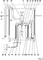
- the pipeline 44 is arranged starting from a suction section 46 with a knee 48 below a maximum filling level 50 of the storage volume 4 ( Fig. 1 , Fig. 2 ).
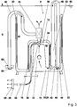
- the knee 48 is arranged above a maximum filling level 50 of the storage volume 4 (cf. Fig. 3 ).
- the surge pot 8 is first heated with the aid of the heating elements 16, 18, 20, 22. Liquid 6 is conveyed from the suction section 46 of the pump 10 into the metering line 32 and towards the jet pump 34
- Liquid 6 reaches a distribution device 56 with nozzles 58 via the metering line 32.
- the pump 10 produces a propellant steel in the heating and pumping operation, which leads to the suction of liquid 6 from the storage volume 4 via a heatable pipe 60.
- the pipeline 60 is routed close to the heating device 20, so that the pipeline can also be heated with the aid of the heating device 20. In this way, liquid 6 is circulated and liquid 6 which may have frozen up can be thawed.
- a mushroom head valve 64 can be assigned to a suction opening 62 of the pipeline 60.
- the pump 10 In a flushing mode, the pump 10 is operated in the opposite direction and run empty so that air is sucked in in the area of the nozzles 58. The pump 10 is completely emptied of liquid 6 in this way, so that there is no longer any liquid inside the pump 10 and also inside the filter 52.
Landscapes
- Engineering & Computer Science (AREA)
- Chemical & Material Sciences (AREA)
- Combustion & Propulsion (AREA)
- Mechanical Engineering (AREA)
- Chemical Kinetics & Catalysis (AREA)
- Transportation (AREA)
- Health & Medical Sciences (AREA)
- Toxicology (AREA)
- General Engineering & Computer Science (AREA)
- Structures Of Non-Positive Displacement Pumps (AREA)
- Cookers (AREA)
Description
- Die Erfindung betrifft einen Flüssigkeitsbehälter für ein Kraftfahrzeug, mit einem Vorratsvolumen zur Bevorratung einer Flüssigkeit, mit einem Schwalltopf, der innerhalb des Vorratsvolumens angeordnet ist, und mit einer Pumpe.
- In modernen Kraftfahrzeugen werden wässrige Betriebsflüssigkeiten beispielsweise eingesetzt, um die Motorleistung zu steigern oder den Schadstoffausstoß zu verringern. So sind beispielsweise Systeme zur Wasserinjektion bekannt.
- Die in einem Flüssigkeitsbehälter mitgeführten, wässrigen Betriebsflüssigkeiten können bei entsprechend niedrigen Außentemperaturen einfrieren. In einem solchen Fall ist ein schnelles Auftauen der wässrigen Betriebsflüssigkeit erforderlich, um einen Fördern zu ermöglichen und die entsprechenden Systeme mit der Flüssigkeit zu versorgen.
- Hierzu ist es bekannt, in einem Vorratsvolumen einen Schwalltopf anzuordnen, der ein Nebenvolumen abgrenzt, in dem gezielt und zügig aufgetaut werden kann um eine schnelle Betriebsbereitschaft des jeweiligen Systems zu erreichen. Dem Schwalltopf ist üblicherweise ein Pumpenmodul zugeordnet, das über Leitungen mit dem Schwalltopf verbunden ist. Die Flüssigkeit wird demnach aus dem Schwalltopf gefördert und beispielsweise Injektionsdüsen zugeführt. Zum Beispiel, offenbart
DE 10 2005 000 730 A1 offenbart einen zweiteiligen Kraftstoffbehälter. Hierbei ist nachteilig, dass der Schwalltopf zusammen mit dem Pumpenmodul ein Volumenverlust von bis zu 10 % des Vorratsvolumens mit sich bringt. Das Pumpenmodul muss über eine separate Heizung beheizt werden. Verbindungsleitungen zwischen der Pumpe und dem Schwalltopf bzw. der Pumpe und dem Flüssigkeitsbehälter müssen ebenfalls separat beheizt werden. - Ausgehend von dem voranstehend beschriebenen Stand der Technik liegt der Erfindung die technische Problemstellung zugrunde, einen Flüssigkeitsbehälter für ein Kraftfahrzeug anzugeben, der die voranstehend beschriebenen Nachteile nicht oder zumindest in geringerem Maße aufweist, und insbesondere eine verbesserte Ausnutzung des Vorratsvolumens und eine reduzierte Systemkomplexität mit sich bringt.
- Die voranstehend beschriebene technische Problemstellung wird gelöst durch einen Flüssigkeitsbehälter nach Anspruch 1. Weitere Ausgestaltungen der Erfindung ergeben sich aus den abhängigen Ansprüchen und der nachstehenden Beschreibung.
- Es wird ein Flüssigkeitsbehälter für ein Kraftfahrzeug angegeben, mit einem Vorratsvolumen zur Bevorratung einer Flüssigkeit, mit einem Schwalltopf, der innerhalb des Vorratsvolumens angeordnet ist, und mit einer Pumpe. Der Schwalltopf hat eine Einstülpung zur Aufnahme einer Pumpe und die Pumpe sitzt zumindest abschnittsweise in der Einstülpung. Durch die zumindest teilweise Integration der Pumpe in eine Umhüllende des Schwalltopfs kann das von Schwalltopf und Pumpe eingenommene Volumen innerhalb des Vorratsvolumens reduziert werden. Die Pumpe wird demnach zumindest abschnittsweise umfangsseitig von dem Schwalltopf eingefasst.
- Die zumindest abschnittweise Integration der Pumpe in den Schwalltopf hat zudem den Vorteil, dass ein Wärmeeintrag im Bereich des Schwalltopfs auch zum Erwärmen der Pumpe genutzt werden kann. So kann beispielsweise eine zum Erwärmen des Schwalltopfs eingerichtete Heizeinrichtung auch die Pumpe erwärmen, so dass eine separate Heizung für die Pumpe entfallen kann. Die zumindest abschnittweise Integration der Pumpe in den Schwalltopf hat zudem den Vorteil, dass Verbindungsleitungen und die dafür ebenfalls erforderlichen Heizeinrichtungen zwischen der Pumpe und dem Schwalltopf entfallen können.
- Die Einstülpung kann ein Einzug sein, der beim Tiefziehen oder Spritzgießen des Schwalltopfs hergestellt worden ist.
- Die Pumpe kann von einer äußeren Oberfläche einer Wandung des Schwalltopfs zumindest abschnittsweise umfangsseitig eingefasst sein, wobei eine oder mehrere Durchgangsöffnungen in der Wandung des Schwalltopfs vorgesehen sind, um Flüssigkeit aus einem oder in ein durch den Schwalltopf gebildetes Nebenvolumen zu fördern. Die Pumpe ist daher über die Durchgangsöffnungen und ggf. zwischengeschaltete Ventile oder Leitungsabschnitte mit dem Nebenvolumen fluidverbunden. Ventile oder Leitungsabschnitte können dabei zumindest abschnittsweise, insbesondere vollständig, in eine Umhüllende des Schwalltopfs integriert sein.
- Nach einer weiteren Ausgestaltung des Flüssigkeitsbehälters ist vorgesehen, dass die Pumpe vollständig in der Einstülpung sitzt. Auf diese Weise kann eine besonders kompakte Anordnung der Pumpe realisiert werden.
- Die Einstülpung kann in einem Boden des Schwalltopfs vorgesehen sein. Eine derartige Anordnung ist fertigungstechnisch besonders einfach realisierbar und ermöglicht eine funktionsgerechte Orientierung der Pumpe innerhalb des Flüssigkeitsbehälters.
- Nach einer weiteren Ausgestaltung des Flüssigkeitsbehälters ist ein Heizelement vorgesehen oder es sind mehrere Heizelemente vorgesehen. Wenigstens ein Heizelement ist zum Erwärmen einer die Einstülpung begrenzenden Wandung und/oder zum Erwärmen der Pumpe eingerichtet. Ein solches Heizelement beschleunigt die Einsatzbereitschaft eines mit dem Flüssigkeitsbehälter gekoppelten Systems in einem Kraftfahrzeug soweit die zu bevorratende Flüssigkeit gefroren ist oder die Viskosität der Flüssigkeit verringert werden soll.
- Insbesondere kann wenigstens ein Heizelement derart angeordnet sein, dass es sowohl eine die Einstülpung begrenzende Wandung erwärmt und auch eine Erwärmung der Pumpe bewirkt. Damit kann ein zusätzliches Heizelement für die Pumpe entfallen.
- Wenigstens ein Heizelement kann auf der die Einstülpung begrenzenden Wandung angeordnet sein. Beispielsweise kann ein Heizelement mit der Wandung verklebt sein. Damit lässt sich eine flexible und kostengünstige Anordnung von einem Heizelement oder mehreren Heizelementen erreichen.
- Alternativ oder ergänzend kann vorgesehen sein, dass wenigstens ein Heizelement abschnittsweise oder vollständig in die die Einstülpung begrenzende Wandung integriert ist. Auf diese Weise kann eine Beschädigung des Heizelements durch Korrosion oder andere Umgebungseinflüsse vermieden werden.
- Wenigstens ein Heizelement kann dazu eingerichtet sein, die die Einstülpung begrenzende Wandung beidseitig flächig zu erwärmen. Auf diese Weise kann ein Wärmeeintrag sowohl in ein durch den Schwalltopf begrenztes Nebenvolumen als auch in Richtung der Pumpe erfolgen.
- Es kann vorgesehen sein, dass wenigstens ein Heizelement integraler Bestandteil der die Einstülpung begrenzenden Wandung ist, wobei das Heizelement ein Polymer aufweist, das einen positiven Temperaturkoeffizienten hat, und wobei Elektroden mit dem Polymer verbunden sind, die zum Übertragen eines elektrischen Stroms zum Erwärmen des Polymers eingerichtet sind, insbesondere, dass das Heizelement vollständig von einem Kunststoff der Wandung eingefasst ist.
- Das Heizelement kann ein PTC-Heizelement sein. Die Verwendung eines PTC-Heizelements hat den Vorteil, dass aufgrund des Temperaturverhaltens des Polymers auf eine Steuerung zum Vermeiden von Überhitzen verzichtet werden kann. So kann auch bei geringem Füllstand des Schwalltopfs eine Beschädigung der Heizeinrichtung durch Überhitzen vermieden werden, da durch den mit steigender Temperatur stark ansteigenden Widerstand des Polymers eine Selbstabschaltung der PTC-Heizeinrichtung erfolgt.
- Das Heizelement kann aus einem Polymer bestehen, wobei das Polymer einen positiven Temperaturkoeffizienten hat. Das Polymer des Heizelements ist insbesondere mithilfe der Elektroden erwärmbar, wobei die Elektroden zum Einleiten einer Heizleistung mit einer elektrischen Energiequelle koppelbar oder gekoppelt sind, insbesondere mit einer Spannungsquelle.
- Bei dem Polymer kann es sich um ein bei Raumtemperatur festes oder pastöses Material handeln.
- Das Polymer kann ein thermoplastisches Material sein.
- Das Polymer kann ein Polyethylen (PE) sein.
- Das Polymer kann Additive enthalten, die eine elektrische Leitfähigkeit des Polymers bewirken oder erhöhen. Beispielsweise kann das Polymer Ruß als Additiv aufweisen. Bei dem Additiv kann es sich um ein nichtmetallisches Additiv handeln. Die Elektroden können eine im Wesentlichen linienförmige Gestalt haben, d.h. schmal und länglich ausgebildet sein, oder plattenförmig ausgestaltet sein. Insbesondere die plattenförmige Gestalt bietet den Vorteil, dass eine flächige Einbringung einer Heizleistung erfolgen kann.
- Die Elektroden können zum Einleiten eines Stromflusses quer zu einer Wandungsfläche des Schwalltopfs eingerichtet sind. Insbesondere können Elektroden vorgesehen sein, die zum Einleiten eines Stromflusses senkrecht zu einer Wandungsfläche des Schwalltopfs eingerichtet sind.
- Alternativ können die Elektroden zum Einleiten eines Stromflusses entlang einer Wandungsfläche des Schwalltopfs eingerichtet sein. Insbesondere können Elektroden vorgesehen sein, die zum Einleiten eines Stromflusses parallel zu einer Wandungsfläche des Schwalltopfs eingerichtet sind.
- Einem Heizelement zugeordnete Elektroden können linienförmig sein.
- Einem Heizelement zugeordnete Elektroden können plattenförmig sein.
- Beispielsweise können einem ersten Heizelement linienförmige Elektroden oder plattenförmige Elektroden zugeordnet sein. Einem zusätzlichen, zweiten Heizelement können linienförmige Elektroden oder plattenförmige Elektroden zugeordnet sein. Das erste Heizelement kann in einer Seitenwand des Schwalltopfs angeordnet sein. Das zweite Heizelement kann in einem Boden des Schwalltopfs angeordnet sein.
- Um die Elektroden vor einer Beschädigung zu schützen, können die Elektroden zumindest teilweise von einem Kunststoff einer Wandung des Schwalltopfs bedeckt sein.
- Das Heizelement kann eines oder mehrere Keramik-PTC-Elemente, sogenannte "PTC-Steine" aufweisen, die ganz oder teilweise in eine Wandung des Schwalltopfs eingebettet sein können. Diese PTC-Steine können auf einem oder mehreren metallischen Wärmeleitkörpern sitzen, z.B. aus Aluminium, um die im Heizbetrieb lokal sehr hohe Wärmedichte der PTC-Steine flächig zu verteilen. Die metallischen Wärmeleitkörper können ebenfalls ganz oder teilweise in die Wandung des Schwalltopfs eingebettet sein.
- Um eine möglichst gute Wärmeübertragung zwischen der Pumpe und dem Schwalltopf zu erreichen, ist zwischen der Pumpe und dem Schwalltopf eine wärmeleitfähige Vergussmasse vorgesehen, wobei die Vergussmasse die Pumpe und den Schwalltopf im Bereich der Einstülpung zumindest abschnittsweise spaltfrei verbindet.
- Bei der Vergussmasse kann es sich beispielsweise um ein Silikonelastomer handeln, das eine Härte von 30-60 Shore(A) hat und eine Wärmeleitfähigkeit von 1,5-3 W/(m*K).
- Die Pumpe kann mit einer Dosierleitung verbunden sein, wobei die Dosierleitung im Bereich der Einstülpung zumindest abschnittsweise zwischen der Pumpe und dem Schwalltopf verläuft. Auf diese Weise können der Pumpe und oder dem Schwalltopf zugeordnete Heizelemente auch zum Erwärmen der Dosierleitung eingerichtet sein.
- Es kann insbesondere vorgesehen sein, dass eine zwischen der Pumpe und dem Schwalltopf verlaufende Dosierleitung von einer den Schwalltopf und die Pumpe verbindenden Vergussmasse eingefasst ist.
- Um in einfacher Weise ein Fördern von Flüssigkeit aus dem Vorratsvolumen in den Schwalltopf zu erreichen, kann eine Strahlpumpe vorgesehen sein. Die Pumpe ist zum Erzeugen eines Treibstrahls mit der Strahlpumpe gekoppelt.
- An einem Pumpenauslass der Pumpe kann ein Ventil angeordnet sein, das zum Verhindern eines Flüssigkeitseintritts bei Stillstand der Pumpe eingerichtet ist. Insbesondere kann das Ventil dazu eingerichtet sein, ein Eindringen von Flüssigkeit aus einem durch den Schwalltopf definierten Nebenvolumen beim Stillstand der Pumpe in die Pumpe zu vermeiden.
- Wenn vorliegend von einem Nebenvolumen gesprochen wird, so handelt es sich dabei um ein durch eine Innenseite einer Wandung des Schwalltopfs begrenztes Volumen, dass einer der Pumpe zugeordneten Außenseite der Wandung abgewandt ist.
- Soweit der Schwalltopf unterhalb eines maximalen Füllstandes der Flüssigkeit in dem Vorratsvolumen angeordnet ist, besteht die Möglichkeit, dass beim Gefrieren der Flüssigkeit der Schwalltopf vollständig von einer Eismasse eingefasst ist bzw. von einer Eisfläche überspannt wird. In einem solchen Fall besteht die Gefahr, dass durch ein Einschalten der Pumpe und eine Entnahme von Flüssigkeit aus dem Tank unterhalb der Eisfläche ein Unterdruck erzeugt wird bzw. innerhalb eines geschlossenen Eisblocks eine Kavität gebildet wird. Nach einer gewissen Anlaufzeit ist ein Fördern von Flüssigkeit nicht mehr möglich, da keine Belüftung des Ansaugbereichs der Pumpe stattfinden kann.
- Um eine zuverlässige Belüftung zu erreichen, kann ein Pumpenzulauf der Pumpe eine Rohrleitung haben, die ausgehend von einem Ansaugabschnitt zumindest abschnittsweise oberhalb einer maximalen Füllhöhe des Vorratsvolumens verläuft. Soweit erwärmte Flüssigkeit durch diese Rohrleitung strömt, wird umfangsseitig an die Rohrleitung angrenzendes Eis, aufgeschmolzen sodass eine Belüftung des Ansaugbereichs erreicht werden kann.
- Es kann eine Ansaugöffnung zum Fördern von Flüssigkeit aus dem Vorratsvolumen in das Nebenvolumen des Schwalltopfs vorgesehen sein, der ein Pilzkopfventil zugeordnet ist. Das Pilzkopfventil erlaubt eine Erstbefüllung des Schwalltopfs bei Erstbefüllung des Flüssigkeitsbehälters. Zudem bewirkt das Pilzkopfventil, dass der Schwalltopf leerlaufsicher ist, insbesondere in Fällen, in denen der Pumpe keine Energie zugeführt wird und die Pumpe stillsteht.
- Eine Ansaugöffnung zum Fördern von Flüssigkeit aus dem Vorratsvolumen in das Nebenvolumen des Schwalltopfs kann zu dem Schwalltopf beabstandet sein. Alternativ kann eine solche Ansaugöffnung in eine Seitenwandung oder einen Boden des Schwalltops integriert sein. In diesem Fall können eine Ansaugleitung und eine ggf. erforderliche Heizeinrichtung zum Erwärmen einer solchen Ansaugleitung entfallen.
- Ein Pumpenzulauf der Pumpe kann einen Filter haben, der in einem fallenden Rohrabschnitt des Pumpenzulaufs angeordnet ist. Auf diese Weise kann erreicht werden, dass der Filter durch ein Leerfahren der Pumpe trockengelegt werden kann. Es kann damit vermieden werden, dass sich Flüssigkeit in dem Filter ansammelt, die beispielsweise vor einem Start eines Wasserinjektionssystems gegebenenfalls aufgetaut werden muss und den Systemstart damit verzögert.
- Nachstehend wird die Erfindung anhand einer Ausführungsbeispiele darstellenden Zeichnung näher beschrieben: es zeigen jeweils schematisch:
- Fig. 1A
- einen erfindungsgemäßen Flüssigkeitsbehälter;
- Fig. 1B
- eine Ausgestaltung eines Heizelements;
- Fig. 1C
- eine weitere Ausgestaltung eines Heizelements;
- Fig. 2
- einen vergrößerten Ausschnitt der
Fig. 1 ; - Fig. 3
- eine Variante des Flüssigkeitsbehälters.
-
Fig. 1A zeigt einen Flüssigkeitsbehälter 2 für ein Kraftfahrzeug. Der Flüssigkeitsbehälter 2 hat ein Vorratsvolumen 4 zur Bevorratung einer Flüssigkeit 6. - Innerhalb des Vorratsvolumens 4 ist ein Schwalltopf 8 angeordnet.
- Innerhalb des Vorratsvolumens 4 ist eine Pumpe 10 angeordnet.
- Der Schwalltopf 8 hat eine Einstülpung 12 zur Aufnahme der Pumpe 10. Die Pumpe 10 sitzt vorliegend vollständig in der Einstülpung 12. Die Einstülpung 12 ist hier als Einzug in einem Spritzgussverfahren hergestellt worden.
- Die Einstülpung 12 ist in einem Boden 14 des Schwalltopfs 8 vorgesehen. Es sind Heizelemente 16, 18, 20, 22 vorgesehen.
- Die Heizelemente 16 und 18 sind zum Erwärmen einer die Einstülpung 12 begrenzenden Wandung 24 und zum Erwärmen der Pumpe 10 eingerichtet. Die Heizelemente 16, 18 sind integraler Bestandteil der die Einstülpung 12 begrenzenden Wandung 24 des Schwalltopfs 8. Die Heizelemente 20, 22 sind in analoger Weise vollständig von der Wandung 24 des Schwalltopfs 8 eingefasst. Das Heizelement 20 ist vollständig von einem Kunststoff 13 der Wandung 24 eingefasst. Das Heizelement 20 weist demnach keinen unmittelbaren Kontakt zu der Flüssigkeit 6 auf.
- Das Heizelement 20 ist vorliegend eine PTC-Heizelement 20. Das Heizelement 20 besteht vorliegend aus einem Polymer 11, wobei das Polymer 11 einen positiven Temperaturkoeffizienten hat. Das bedeutet, dass der elektrische Widerstand des Polymers 11 mit steigender Temperatur zunimmt.
- Es sind Elektroden 19, 21, 26, 28 vorgesehen, die mit dem Polymer 11 verbunden sind. Das Polymer 11 ist vorliegend bei Raumtemperatur fest. Gemäß alternativen Ausgestaltungen kann jedoch vorgesehen sein, dass es sich bei dem Polymer um ein bei Raumtemperatur pastöses Material handelt, dass in die Wandung 24 eingebettet ist.
- Das Polymer 11 ist vorliegend mit Additiven versetzt, um die elektrische Leitfähigkeit des Polymers zu bewirken oder zu erhöhen. Gemäß
Fig. 1C sind die Elektroden 26, 28 zum Einleiten eines Stromflusses 15 entlang einer Wandungsfläche 17 des Schwalltopfs 8 eingerichtet. GemäßFig. 1C ist der Stromfluss 15 insbesondere parallel zu der Wandungsfläche 17 des Schwalltopfs 8 orientiert. - Gemäß
Fig. 1B sind die Elektroden 19, 21 zum Einleiten des Stromflusses 15 quer zu der Wandungsfläche 17 des Schwalltopfs 8 eingerichtet. GemäßFig. 1B ist der Stromfluss 15 insbesondere senkrecht zur Wandungsfläche 17 des Schwalltopfs 8 orientiert. - Wie
Fig. 1B zu entnehmen ist, sind die Elektroden 19, 21 gemäßFig. 1C plattenförmige Elektroden 19, 21 und stellen eine flächige Verteilung von Wärme 23 sicher. - Gemäß der Alternative nach
Fig. 1C sind im Wesentlichen linienförmige Elektroden 26, 28 vorgesehen. - Zwischen der Pumpe und dem Schwalltopf 8 ist eine wärmeleitfähige Vergussmasse 30 vorgesehen. Die Vergussmasse 30 verbindet die Pumpe 10 und den Schwalltopf 8 im Bereich der Einstülpung 12 spaltfrei.
- Die Pumpe 10 ist mit einer Dosierleitung 32 verbunden. Die Dosierleitung 32 ist im Bereich der Einstülpung 12 zwischen der Pumpe 10 und dem Schwalltopf 8 erstreckt. Dabei ist die Dosierleitung 32 in die Vergussmasse 30 eingebettet bzw. von der Vergussmasse 30 umschlossen.
- Es ist eine Strahlpumpe 34 zum Fördern von Flüssigkeit 6 aus dem Vorratsvolumen 4 in den Schwalltopf 8 vorgesehen. Die Pumpe 10 ist zum Erzeugen eines Treibstrahls mit der Strahlpumpe 34 gekoppelt.
- An einem Pumpenauslass 36 der Pumpe 10 ist ein Ventil 38 angeordnet. Das Ventil 38 ist zum Verhindern eines Flüssigkeitseintritts bei Stillstand der Pumpe 10 eingerichtet. Das Ventil 38 verhindert ein Volllaufen der Pumpe nach dem Leerfahren der Pumpe. Es wird verhindert, dass Flüssigkeit 6 aus einem durch den Schwalltopf 8 begrenzten Nebenvolumen 40 in die Pumpe 10 eindringen kann.
- Ein Pumpenzulauf 42 der Pumpe 10 hat eine Rohrleitung 44. Die Rohrleitung 44 ist ausgehend von einem Ansaugabschnitt 46 mit einem Knie 48 unterhalb einer maximalen Füllhöhe 50 des Vorratsvolumens 4 angeordnet (
Fig. 1 ,Fig. 2 ). - Gemäß einer Variante ist das Knie 48 oberhalb einer maximalen Füllhöhe 50 des Vorratsvolumens 4 angeordnet (vergleiche
Fig. 3 ) . - In einem Pump- und Heizbetrieb wird der Schwalltopf 8 zunächst mithilfe der Heizelemente 16, 18, 20, 22 erwärmt. Flüssigkeit 6 wird von dem Ansaugabschnitt 46 der Pumpe 10 in die Dosierleitung 32 und hin zu der Strahlpumpe 34 gefördert
- Über die Dosierleitung 32 gelangt Flüssigkeit 6 zu einer Verteileinrichtung 56 mit Düsen 58.
- Im Bereich der Strahlpumpe 34 bewirkt die Pumpe 10 im Heiz- und Pumpbetrieb einen Treibstahl, der zum Ansaugen von Flüssigkeit 6 aus dem Vorratsvolumen 4 über eine beheizbare Rohrleitung 60 führt. Die Rohrleitung 60 wird nahe der Heizeinrichtung 20 geführt, so dass die Rohrleitung ebenfalls mithilfe der Heizeinrichtung 20 erwärmbar ist. Auf diese Weise wird ein Umwälzen von Flüssigkeit 6 bewirkt und gegebenenfalls vereiste Flüssigkeit 6 kann aufgetaut werden.
- Einer Ansaugöffnung 62 der Rohrleitung 60 kann ein Pilzkopfventil 64 zugeordnet sein.
- In einem Spülbetrieb wird die Pumpe 10 in umgekehrter Richtung betrieben und leer gefahren, sodass im Bereich der Düsen 58 Luft angesaugt wird. Die Pumpe 10 wird auf diese Weise vollständig von Flüssigkeit 6 entleert, so dass innerhalb der Pumpe 10 und auch innerhalb des Filters 52 keine Flüssigkeit mehr vorhanden ist.
-
- 2
- Flüssigkeitsbehälter
- 4
- Vorratsvolumen
- 8
- Schwalltopf
- 10
- Pumpe
- 11
- Polymer
- 12
- Einstülpung
- 13
- Kunststoff
- 14
- Boden
- 15
- Stromfluss
- 16
- Heizelement
- 17
- Wandungsfläche
- 18
- Heizelement
- 19
- plattenförmige Elektrode
- 20
- Heizelement
- 21
- plattenförmige Elektrode
- 22
- Heizelement
- 23
- Wärme
- 24
- Wandung der Einstülpung 12
- 26
- Elektrode
- 28
- Elektrode
- 30
- Vergussmasse
- 32
- Dosierleitung
- 34
- Strahlpumpe
- 36
- Pumpenauslass
- 38
- Ventil
- 40
- Nebenvolumen
- 42
- Zulauf
- 44
- Rohrleitung
- 46
- Ansaugbereich / Ansaugabschnitt
- 48
- Knie
- 50
- maximale Füllhöhe
- 52
- Filter
- 56
- Verteileinrichtung
- 58
- Düse
- 60
- Rohrleitung
- 62
- Ansaugöffnung
- 64
- Pilzkopfventil
Claims (10)
- Flüssigkeitsbehälter für ein Kraftfahrzeug,- mit einem Vorratsvolumen (4) zur Bevorratung einer Flüssigkeit (6),- mit einem Schwalltopf (8), der innerhalb des Vorratsvolumens (4) angeordnet ist, und- mit einer Pumpe (10),- wobei der Schwalltopf (8) eine Einstülpung (12) zur Aufnahme der Pumpe (10) hat und- die Pumpe (10) zumindest abschnittsweise in der Einstülpung (12) sitzt,
dadurch gekennzeichnet, dass- zwischen der Pumpe (10) und dem Schwalltopf (8) eine wärmeleitfähige Vergussmasse (30) vorgesehen ist,- wobei die Vergussmasse (30) die Pumpe (10) und den Schwalltopf (8) im Bereich der Einstülpung (12) zumindest abschnittsweise spaltfrei verbindet. - Flüssigkeitsbehälter nach Anspruch 1,
dadurch gekennzeichnet, dass- die Pumpe (10) vollständig in der Einstülpung (12) sitzt. - Flüssigkeitsbehälter nach einem der Ansprüche 1 oder 2,
dadurch gekennzeichnet, dass- die Einstülpung (12) in einem Boden (14) des Schwalltopfs (8) vorgesehen ist. - Flüssigkeitsbehälter nach einem der voranstehenden Ansprüche,
dadurch gekennzeichnet, dass- ein Heizelement (16, 18, 20, 22) vorgesehen ist oder mehrere Heizelemente (16, 18, 20, 22) vorgesehen sind,- wobei wenigstens ein Heizelement (16, 18, 20, 22) zum Erwärmen einer die Einstülpung (12) begrenzenden Wandung (24) und/oder zum Erwärmen der Pumpe (10) eingerichtet ist. - Flüssigkeitsbehälter nach Anspruch 4,
dadurch gekennzeichnet, dass- wenigstes ein Heizelement (16, 18, 20, 22) auf der die Einstülpung (12) begrenzenden Wandung (24) angeordnet ist und/oder- wenigstens ein Heizelement (16, 18, 20, 22) abschnittweise oder vollständig in die die Einstülpung (12) begrenzende Wandung (24) integriert ist
und/oder- wenigstens ein Heizelement (16, 18, 20, 22) dazu eingerichtet ist, die die Einstülpung (12) begrenzende Wandung (24) beidseitig flächig zu Erwärmen. - Flüssigkeitsbehälter nach einem der Ansprüche 4 oder 5,
dadurch gekennzeichnet, dass- wenigstens ein Heizelement (16, 18, 20, 22) integraler Bestandteil der die Einstülpung (12) begrenzenden Wandung (24) ist,- wobei das Heizelement (16, 18, 20, 22) ein Polymer (11) aufweist, das einen positiven Temperaturkoeffizienten hat, und- wobei Elektroden (19, 21, 26, 28) mit dem Polymer (11) verbunden sind, die zum Übertragen eines elektrischen Stroms zum Erwärmen des Polymers (11) eingerichtet sind- insbesondere, dass das Heizelement (16, 18, 20, 22) vollständig von einem Kunststoff (13) der Wandung (24) eingefasst ist. - Flüssigkeitsbehälter nach einem der voranstehenden Ansprüche,
dadurch gekennzeichnet, dass- die Pumpe (10) mit einer Dosierleitung (32) verbunden ist,- wobei die Dosierleitung (32) im Bereich der Einstülpung (12) zumindest abschnittsweise zwischen der Pumpe (10) und dem Schwalltopf (8) verläuft. - Flüssigkeitsbehälter nach einem der voranstehenden Ansprüche,
dadurch gekennzeichnet, dass- eine Strahlpumpe (34) zum Fördern von Flüssigkeit (6) aus dem Vorratsvolumen (4) in den Schwalltopf (8) vorgesehen ist,- wobei die Pumpe (10) zum Erzeugen eines Treibstrahls mit der Strahlpumpe (34) gekoppelt ist. - Flüssigkeitsbehälter nach einem der voranstehenden Ansprüche,
dadurch gekennzeichnet, dass- wenigstens ein Ventil (38) an einem Pumpenauslass (36) der Pumpe (10) angeordnet ist, dass zum Verhindern eines Flüssigkeitseintritts bei Stillstand der Pumpe (10) eingerichtet ist. - Flüssigkeitsbehälter nach einem der voranstehenden Ansprüche,
dadurch gekennzeichnet, dass- ein Pumpenzulauf (42) der Pumpe (10) eine Rohrleitung (44) hat, die ausgehend von einem Ansaugabschnitt (46) zumindest abschnittsweise oberhalb einer maximalen Füllhöhe (50) des Vorratsvolumens (4) verläuft.
und/oder- ein Pumpenzulauf (42) der Pumpe einen Filter (52) hat, der in einem fallenden Rohrabschnitt des Pumpenzulaufs (42) abgeordnet ist.
Applications Claiming Priority (2)
| Application Number | Priority Date | Filing Date | Title |
|---|---|---|---|
| DE102017115820.0A DE102017115820A1 (de) | 2017-07-13 | 2017-07-13 | Flüssigkeitsbehälter für ein Kraftfahrzeug |
| PCT/EP2018/068704 WO2019011934A1 (de) | 2017-07-13 | 2018-07-10 | Flüssigkeitsbehälter für ein kraftfahrzeug |
Publications (2)
| Publication Number | Publication Date |
|---|---|
| EP3652012A1 EP3652012A1 (de) | 2020-05-20 |
| EP3652012B1 true EP3652012B1 (de) | 2021-08-04 |
Family
ID=62952058
Family Applications (1)
| Application Number | Title | Priority Date | Filing Date |
|---|---|---|---|
| EP18742739.8A Active EP3652012B1 (de) | 2017-07-13 | 2018-07-10 | Flüssigkeitsbehälter für ein kraftfahrzeug |
Country Status (3)
| Country | Link |
|---|---|
| EP (1) | EP3652012B1 (de) |
| DE (1) | DE102017115820A1 (de) |
| WO (1) | WO2019011934A1 (de) |
Family Cites Families (13)
| Publication number | Priority date | Publication date | Assignee | Title |
|---|---|---|---|---|
| FR2663991A1 (fr) * | 1990-06-27 | 1992-01-03 | Renault | Dispositif de retention du combustible dans la conduite d'aspiration du circuit d'alimentation d'un moteur. |
| DE19504217C2 (de) * | 1995-02-09 | 2002-11-14 | Bosch Gmbh Robert | Vorrichtung zum Fördern von Kraftstoff aus einem Vorratstank zur Brennkraftmaschine eines Kraftfahrzeuges |
| DE19651652A1 (de) * | 1996-12-12 | 1998-06-18 | Bosch Gmbh Robert | Kraftstoffbehälter |
| DE19963933A1 (de) * | 1999-12-31 | 2001-07-12 | Bosch Gmbh Robert | Kontaktschutzgehäuse, Einspritzpumpe und Verfahren zum Montieren eines Kontaktschutzgehäuses mit Hilfe eines Adapters |
| DE102005000730B4 (de) * | 2005-01-04 | 2015-10-22 | Continental Automotive Gmbh | Kraftstoffvorratsbehälter |
| FR2918576B1 (fr) * | 2007-07-10 | 2009-10-09 | Inergy Automotive Systems Res | Systeme d'alimentation d'un liquide pour vehicule et module pompe/filtre integre. |
| WO2010119116A2 (en) * | 2009-04-16 | 2010-10-21 | Inergy Automotive Systems Research (Société Anonyme) | System and process for storing an additive and injecting it into the exhaust gases of an engine |
| DE102010004614B4 (de) * | 2010-01-13 | 2025-03-13 | Vitesco Technologies GmbH | Vorrichtung zur Bereitstellung von flüssigem Reduktionsmittel |
| DE102010051072B4 (de) * | 2010-11-12 | 2012-11-08 | Kautex Textron Gmbh & Co. Kg | Flüssigkeitsbehälter, insbesondere für eine wässrige Harnstofflösung |
| KR101317415B1 (ko) * | 2011-10-05 | 2013-10-10 | 현대자동차주식회사 | 차량의 선택적 촉매 환원 장치용 요소 펌프 모듈 |
| CN105492732B (zh) * | 2013-06-13 | 2018-11-23 | 大陆汽车有限责任公司 | 用于提供液体添加剂的装置及其运行方法和机动车辆 |
| DE102015204353B4 (de) * | 2015-03-11 | 2026-04-02 | Bayerische Motoren Werke Aktiengesellschaft | Behälter für ein flüssiges Betriebsmittel eines Kraftfahrzeuges und Kraftfahrzeug mit einem solchen Behälter |
| DE102015212524B8 (de) * | 2015-07-03 | 2017-04-13 | Kautex Textron Gmbh & Co. Kg | Auftauvorrichtung für Betriebsflüssigkeitsbehälter |
-
2017
- 2017-07-13 DE DE102017115820.0A patent/DE102017115820A1/de not_active Ceased
-
2018
- 2018-07-10 WO PCT/EP2018/068704 patent/WO2019011934A1/de not_active Ceased
- 2018-07-10 EP EP18742739.8A patent/EP3652012B1/de active Active
Also Published As
| Publication number | Publication date |
|---|---|
| EP3652012A1 (de) | 2020-05-20 |
| WO2019011934A1 (de) | 2019-01-17 |
| DE102017115820A1 (de) | 2019-01-17 |
Similar Documents
| Publication | Publication Date | Title |
|---|---|---|
| DE112006001892B4 (de) | Heizsystem | |
| EP2524121B1 (de) | Vorrichtung mit einem tank und einer fördereinheit für reduktionsmittel | |
| EP3011153B1 (de) | Vorratstank mit heizvorrichtung | |
| DE102009047647B4 (de) | Heizsystem für einen Tankbehälter | |
| WO2011157602A1 (de) | Vorrichtung zur förderung von flüssigem reduktionsmittel | |
| EP2477857A1 (de) | Verbindungseinrichtung für eine scheibenwischeranlage | |
| DE102013001237A1 (de) | Filtervorrichtung für einen Flüssigkeitsbehälter, insbesondere für wässrige Harnstofflösung | |
| DE102015212524B3 (de) | Auftauvorrichtung für Betriebsflüssigkeitsbehälter | |
| DE102015204647A1 (de) | Saugstrahlpumpe und ein Verfahren zur Beheizung der Saugstrahlpumpe | |
| DE202019102644U1 (de) | Flüssigkeitsbehälter für ein Kraftfahrzeug | |
| DE102012025436A1 (de) | Verbrennungskraftmaschine | |
| EP3317134B1 (de) | Auftauvorrichtung für betriebsflüssigkeitsbehälter | |
| DE102017115820A1 (de) | Flüssigkeitsbehälter für ein Kraftfahrzeug | |
| EP3453552B1 (de) | Vorratsbehälter | |
| WO2017190923A1 (de) | Vorratstank zur bevorratung eines gefrierfähigen betriebs- oder hilfsstoffs | |
| DE102017213950A1 (de) | Tankeinrichtung für Abgasnachbehandlungssystem | |
| DE102015017122B4 (de) | Betriebsflüssigkeitsbehälter | |
| DE102019209615A1 (de) | Heizvorrichtung | |
| DE102018111474B4 (de) | Fluidsystem und Verwendung eines bidirektionalen Druckventils | |
| DE102010004613A1 (de) | Vorrichtung mit einem Injektor für ein flüssiges Reduktionsmittel | |
| DE102018218749A1 (de) | Wassereinspritzvorrichtung für eine Brennkraftmaschine | |
| EP3685629B1 (de) | Heizeinrichtung | |
| WO2020070117A1 (de) | Heizvorrichtung zum einbau in einen fahrzeugtank für reduktionsmittel und fahrzeugtank | |
| EP2703058A1 (de) | Auffangbehälter für einen Flüssigkeitsabscheider sowie Verfahren zum Betrieb eines Flüssigkeitsabscheiders | |
| DE102017114333A1 (de) | Betriebsflüssigkeitstank |
Legal Events
| Date | Code | Title | Description |
|---|---|---|---|
| STAA | Information on the status of an ep patent application or granted ep patent |
Free format text: STATUS: UNKNOWN |
|
| STAA | Information on the status of an ep patent application or granted ep patent |
Free format text: STATUS: THE INTERNATIONAL PUBLICATION HAS BEEN MADE |
|
| PUAI | Public reference made under article 153(3) epc to a published international application that has entered the european phase |
Free format text: ORIGINAL CODE: 0009012 |
|
| STAA | Information on the status of an ep patent application or granted ep patent |
Free format text: STATUS: REQUEST FOR EXAMINATION WAS MADE |
|
| 17P | Request for examination filed |
Effective date: 20191218 |
|
| AK | Designated contracting states |
Kind code of ref document: A1 Designated state(s): AL AT BE BG CH CY CZ DE DK EE ES FI FR GB GR HR HU IE IS IT LI LT LU LV MC MK MT NL NO PL PT RO RS SE SI SK SM TR |
|
| AX | Request for extension of the european patent |
Extension state: BA ME |
|
| DAV | Request for validation of the european patent (deleted) | ||
| DAX | Request for extension of the european patent (deleted) | ||
| GRAP | Despatch of communication of intention to grant a patent |
Free format text: ORIGINAL CODE: EPIDOSNIGR1 |
|
| STAA | Information on the status of an ep patent application or granted ep patent |
Free format text: STATUS: GRANT OF PATENT IS INTENDED |
|
| INTG | Intention to grant announced |
Effective date: 20210212 |
|
| GRAS | Grant fee paid |
Free format text: ORIGINAL CODE: EPIDOSNIGR3 |
|
| GRAA | (expected) grant |
Free format text: ORIGINAL CODE: 0009210 |
|
| STAA | Information on the status of an ep patent application or granted ep patent |
Free format text: STATUS: THE PATENT HAS BEEN GRANTED |
|
| AK | Designated contracting states |
Kind code of ref document: B1 Designated state(s): AL AT BE BG CH CY CZ DE DK EE ES FI FR GB GR HR HU IE IS IT LI LT LU LV MC MK MT NL NO PL PT RO RS SE SI SK SM TR |
|
| REG | Reference to a national code |
Ref country code: GB Ref legal event code: FG4D Free format text: NOT ENGLISH |
|
| REG | Reference to a national code |
Ref country code: AT Ref legal event code: REF Ref document number: 1416643 Country of ref document: AT Kind code of ref document: T Effective date: 20210815 |
|
| REG | Reference to a national code |
Ref country code: CH Ref legal event code: EP |
|
| REG | Reference to a national code |
Ref country code: DE Ref legal event code: R096 Ref document number: 502018006449 Country of ref document: DE |
|
| REG | Reference to a national code |
Ref country code: IE Ref legal event code: FG4D Free format text: LANGUAGE OF EP DOCUMENT: GERMAN |
|
| REG | Reference to a national code |
Ref country code: LT Ref legal event code: MG9D |
|
| REG | Reference to a national code |
Ref country code: NL Ref legal event code: MP Effective date: 20210804 |
|
| PG25 | Lapsed in a contracting state [announced via postgrant information from national office to epo] |
Ref country code: BG Free format text: LAPSE BECAUSE OF FAILURE TO SUBMIT A TRANSLATION OF THE DESCRIPTION OR TO PAY THE FEE WITHIN THE PRESCRIBED TIME-LIMIT Effective date: 20211104 Ref country code: LT Free format text: LAPSE BECAUSE OF FAILURE TO SUBMIT A TRANSLATION OF THE DESCRIPTION OR TO PAY THE FEE WITHIN THE PRESCRIBED TIME-LIMIT Effective date: 20210804 Ref country code: PT Free format text: LAPSE BECAUSE OF FAILURE TO SUBMIT A TRANSLATION OF THE DESCRIPTION OR TO PAY THE FEE WITHIN THE PRESCRIBED TIME-LIMIT Effective date: 20211206 Ref country code: NO Free format text: LAPSE BECAUSE OF FAILURE TO SUBMIT A TRANSLATION OF THE DESCRIPTION OR TO PAY THE FEE WITHIN THE PRESCRIBED TIME-LIMIT Effective date: 20211104 Ref country code: FI Free format text: LAPSE BECAUSE OF FAILURE TO SUBMIT A TRANSLATION OF THE DESCRIPTION OR TO PAY THE FEE WITHIN THE PRESCRIBED TIME-LIMIT Effective date: 20210804 Ref country code: ES Free format text: LAPSE BECAUSE OF FAILURE TO SUBMIT A TRANSLATION OF THE DESCRIPTION OR TO PAY THE FEE WITHIN THE PRESCRIBED TIME-LIMIT Effective date: 20210804 Ref country code: HR Free format text: LAPSE BECAUSE OF FAILURE TO SUBMIT A TRANSLATION OF THE DESCRIPTION OR TO PAY THE FEE WITHIN THE PRESCRIBED TIME-LIMIT Effective date: 20210804 Ref country code: SE Free format text: LAPSE BECAUSE OF FAILURE TO SUBMIT A TRANSLATION OF THE DESCRIPTION OR TO PAY THE FEE WITHIN THE PRESCRIBED TIME-LIMIT Effective date: 20210804 Ref country code: RS Free format text: LAPSE BECAUSE OF FAILURE TO SUBMIT A TRANSLATION OF THE DESCRIPTION OR TO PAY THE FEE WITHIN THE PRESCRIBED TIME-LIMIT Effective date: 20210804 |
|
| PG25 | Lapsed in a contracting state [announced via postgrant information from national office to epo] |
Ref country code: PL Free format text: LAPSE BECAUSE OF FAILURE TO SUBMIT A TRANSLATION OF THE DESCRIPTION OR TO PAY THE FEE WITHIN THE PRESCRIBED TIME-LIMIT Effective date: 20210804 Ref country code: LV Free format text: LAPSE BECAUSE OF FAILURE TO SUBMIT A TRANSLATION OF THE DESCRIPTION OR TO PAY THE FEE WITHIN THE PRESCRIBED TIME-LIMIT Effective date: 20210804 Ref country code: GR Free format text: LAPSE BECAUSE OF FAILURE TO SUBMIT A TRANSLATION OF THE DESCRIPTION OR TO PAY THE FEE WITHIN THE PRESCRIBED TIME-LIMIT Effective date: 20211105 |
|
| PG25 | Lapsed in a contracting state [announced via postgrant information from national office to epo] |
Ref country code: NL Free format text: LAPSE BECAUSE OF FAILURE TO SUBMIT A TRANSLATION OF THE DESCRIPTION OR TO PAY THE FEE WITHIN THE PRESCRIBED TIME-LIMIT Effective date: 20210804 |
|
| PG25 | Lapsed in a contracting state [announced via postgrant information from national office to epo] |
Ref country code: DK Free format text: LAPSE BECAUSE OF FAILURE TO SUBMIT A TRANSLATION OF THE DESCRIPTION OR TO PAY THE FEE WITHIN THE PRESCRIBED TIME-LIMIT Effective date: 20210804 |
|
| REG | Reference to a national code |
Ref country code: DE Ref legal event code: R097 Ref document number: 502018006449 Country of ref document: DE |
|
| PG25 | Lapsed in a contracting state [announced via postgrant information from national office to epo] |
Ref country code: SM Free format text: LAPSE BECAUSE OF FAILURE TO SUBMIT A TRANSLATION OF THE DESCRIPTION OR TO PAY THE FEE WITHIN THE PRESCRIBED TIME-LIMIT Effective date: 20210804 Ref country code: SK Free format text: LAPSE BECAUSE OF FAILURE TO SUBMIT A TRANSLATION OF THE DESCRIPTION OR TO PAY THE FEE WITHIN THE PRESCRIBED TIME-LIMIT Effective date: 20210804 Ref country code: RO Free format text: LAPSE BECAUSE OF FAILURE TO SUBMIT A TRANSLATION OF THE DESCRIPTION OR TO PAY THE FEE WITHIN THE PRESCRIBED TIME-LIMIT Effective date: 20210804 Ref country code: EE Free format text: LAPSE BECAUSE OF FAILURE TO SUBMIT A TRANSLATION OF THE DESCRIPTION OR TO PAY THE FEE WITHIN THE PRESCRIBED TIME-LIMIT Effective date: 20210804 Ref country code: CZ Free format text: LAPSE BECAUSE OF FAILURE TO SUBMIT A TRANSLATION OF THE DESCRIPTION OR TO PAY THE FEE WITHIN THE PRESCRIBED TIME-LIMIT Effective date: 20210804 Ref country code: AL Free format text: LAPSE BECAUSE OF FAILURE TO SUBMIT A TRANSLATION OF THE DESCRIPTION OR TO PAY THE FEE WITHIN THE PRESCRIBED TIME-LIMIT Effective date: 20210804 |
|
| PLBE | No opposition filed within time limit |
Free format text: ORIGINAL CODE: 0009261 |
|
| STAA | Information on the status of an ep patent application or granted ep patent |
Free format text: STATUS: NO OPPOSITION FILED WITHIN TIME LIMIT |
|
| 26N | No opposition filed |
Effective date: 20220506 |
|
| PG25 | Lapsed in a contracting state [announced via postgrant information from national office to epo] |
Ref country code: IT Free format text: LAPSE BECAUSE OF FAILURE TO SUBMIT A TRANSLATION OF THE DESCRIPTION OR TO PAY THE FEE WITHIN THE PRESCRIBED TIME-LIMIT Effective date: 20210804 |
|
| PG25 | Lapsed in a contracting state [announced via postgrant information from national office to epo] |
Ref country code: SI Free format text: LAPSE BECAUSE OF FAILURE TO SUBMIT A TRANSLATION OF THE DESCRIPTION OR TO PAY THE FEE WITHIN THE PRESCRIBED TIME-LIMIT Effective date: 20210804 |
|
| PG25 | Lapsed in a contracting state [announced via postgrant information from national office to epo] |
Ref country code: MC Free format text: LAPSE BECAUSE OF FAILURE TO SUBMIT A TRANSLATION OF THE DESCRIPTION OR TO PAY THE FEE WITHIN THE PRESCRIBED TIME-LIMIT Effective date: 20210804 |
|
| REG | Reference to a national code |
Ref country code: CH Ref legal event code: PL |
|
| REG | Reference to a national code |
Ref country code: BE Ref legal event code: MM Effective date: 20220731 |
|
| PG25 | Lapsed in a contracting state [announced via postgrant information from national office to epo] |
Ref country code: LU Free format text: LAPSE BECAUSE OF NON-PAYMENT OF DUE FEES Effective date: 20220710 Ref country code: LI Free format text: LAPSE BECAUSE OF NON-PAYMENT OF DUE FEES Effective date: 20220731 Ref country code: CH Free format text: LAPSE BECAUSE OF NON-PAYMENT OF DUE FEES Effective date: 20220731 |
|
| PG25 | Lapsed in a contracting state [announced via postgrant information from national office to epo] |
Ref country code: BE Free format text: LAPSE BECAUSE OF NON-PAYMENT OF DUE FEES Effective date: 20220731 |
|
| P01 | Opt-out of the competence of the unified patent court (upc) registered |
Effective date: 20230526 |
|
| PG25 | Lapsed in a contracting state [announced via postgrant information from national office to epo] |
Ref country code: IE Free format text: LAPSE BECAUSE OF NON-PAYMENT OF DUE FEES Effective date: 20220710 |
|
| PGFP | Annual fee paid to national office [announced via postgrant information from national office to epo] |
Ref country code: GB Payment date: 20230721 Year of fee payment: 6 |
|
| PGFP | Annual fee paid to national office [announced via postgrant information from national office to epo] |
Ref country code: FR Payment date: 20230726 Year of fee payment: 6 Ref country code: DE Payment date: 20230627 Year of fee payment: 6 |
|
| PG25 | Lapsed in a contracting state [announced via postgrant information from national office to epo] |
Ref country code: MK Free format text: LAPSE BECAUSE OF FAILURE TO SUBMIT A TRANSLATION OF THE DESCRIPTION OR TO PAY THE FEE WITHIN THE PRESCRIBED TIME-LIMIT Effective date: 20210804 Ref country code: CY Free format text: LAPSE BECAUSE OF FAILURE TO SUBMIT A TRANSLATION OF THE DESCRIPTION OR TO PAY THE FEE WITHIN THE PRESCRIBED TIME-LIMIT Effective date: 20210804 |
|
| PG25 | Lapsed in a contracting state [announced via postgrant information from national office to epo] |
Ref country code: HU Free format text: LAPSE BECAUSE OF FAILURE TO SUBMIT A TRANSLATION OF THE DESCRIPTION OR TO PAY THE FEE WITHIN THE PRESCRIBED TIME-LIMIT; INVALID AB INITIO Effective date: 20180710 |
|
| REG | Reference to a national code |
Ref country code: AT Ref legal event code: MM01 Ref document number: 1416643 Country of ref document: AT Kind code of ref document: T Effective date: 20230710 |
|
| PG25 | Lapsed in a contracting state [announced via postgrant information from national office to epo] |
Ref country code: MT Free format text: LAPSE BECAUSE OF FAILURE TO SUBMIT A TRANSLATION OF THE DESCRIPTION OR TO PAY THE FEE WITHIN THE PRESCRIBED TIME-LIMIT Effective date: 20210804 |
|
| PG25 | Lapsed in a contracting state [announced via postgrant information from national office to epo] |
Ref country code: AT Free format text: LAPSE BECAUSE OF NON-PAYMENT OF DUE FEES Effective date: 20230710 |
|
| PG25 | Lapsed in a contracting state [announced via postgrant information from national office to epo] |
Ref country code: AT Free format text: LAPSE BECAUSE OF NON-PAYMENT OF DUE FEES Effective date: 20230710 |
|
| REG | Reference to a national code |
Ref country code: DE Ref legal event code: R119 Ref document number: 502018006449 Country of ref document: DE |
|
| GBPC | Gb: european patent ceased through non-payment of renewal fee |
Effective date: 20240710 |
|
| PG25 | Lapsed in a contracting state [announced via postgrant information from national office to epo] |
Ref country code: DE Free format text: LAPSE BECAUSE OF NON-PAYMENT OF DUE FEES Effective date: 20250201 |
|
| PG25 | Lapsed in a contracting state [announced via postgrant information from national office to epo] |
Ref country code: FR Free format text: LAPSE BECAUSE OF NON-PAYMENT OF DUE FEES Effective date: 20240731 |
|
| PG25 | Lapsed in a contracting state [announced via postgrant information from national office to epo] |
Ref country code: GB Free format text: LAPSE BECAUSE OF NON-PAYMENT OF DUE FEES Effective date: 20240710 |
|
| PG25 | Lapsed in a contracting state [announced via postgrant information from national office to epo] |
Ref country code: TR Free format text: LAPSE BECAUSE OF FAILURE TO SUBMIT A TRANSLATION OF THE DESCRIPTION OR TO PAY THE FEE WITHIN THE PRESCRIBED TIME-LIMIT Effective date: 20210804 |
|
| PGFP | Annual fee paid to national office [announced via postgrant information from national office to epo] |
Ref country code: AT Payment date: 20260410 Year of fee payment: 5 |