EP3652008B1 - Halter für ein flächenelement einer sonnenschutz- oder verdunklungsvorrichtung und sonnenschutz- oder verdunklungsvorrichtung - Google Patents
Halter für ein flächenelement einer sonnenschutz- oder verdunklungsvorrichtung und sonnenschutz- oder verdunklungsvorrichtung Download PDFInfo
- Publication number
- EP3652008B1 EP3652008B1 EP18739506.6A EP18739506A EP3652008B1 EP 3652008 B1 EP3652008 B1 EP 3652008B1 EP 18739506 A EP18739506 A EP 18739506A EP 3652008 B1 EP3652008 B1 EP 3652008B1
- Authority
- EP
- European Patent Office
- Prior art keywords
- holder
- base
- frame
- windowpane
- covering
- Prior art date
- Legal status (The legal status is an assumption and is not a legal conclusion. Google has not performed a legal analysis and makes no representation as to the accuracy of the status listed.)
- Active
Links
Images


Classifications
-
- B—PERFORMING OPERATIONS; TRANSPORTING
- B60—VEHICLES IN GENERAL
- B60J—WINDOWS, WINDSCREENS, NON-FIXED ROOFS, DOORS, OR SIMILAR DEVICES FOR VEHICLES; REMOVABLE EXTERNAL PROTECTIVE COVERINGS SPECIALLY ADAPTED FOR VEHICLES
- B60J1/00—Windows; Windscreens; Accessories therefor
- B60J1/20—Accessories, e.g. wind deflectors, blinds
- B60J1/2011—Blinds; curtains or screens reducing heat or light intensity
Definitions
- the present invention relates to a holder for a surface element of a sun protection or darkening device, which is provided for covering a window pane of a motor vehicle with a covering made of a thin covering material and a peripheral frame, preferably designed as a tensioning frame, wherein the holder has a frame for a section of the receiving space, preferably covered with the covering material, with a receiving opening, which is delimited by a base.
- the invention further relates to a corresponding sun protection or darkening device.
- Holders intended for securing corresponding surface elements of sun protection or darkening devices are known on the market.
- the base has a receiving space on one side with a receiving opening into which the frame must be inserted.
- the holder is attached to a panel or frame part of the vehicle using this adhesive layer.
- the disadvantage here is that the surface to be glued is often not sufficiently pre-treated and is therefore not clean or free of grease.
- the adhesive layer does not provide sufficient adhesion, especially in a heated vehicle interior.
- the surface element The sun protection device is then not sufficiently secured. It can also happen that the adhesive layer cannot be removed without leaving residue, which can lead to problems when replacing the holder or in leased vehicles.
- a holder of this type is further developed in such a way that it has an insertion element pointing away from the base, the end of which is remote from the base and is designed in the form of a hook and which has a contact surface on a side facing the window pane, the base having a support region which is arranged on a side of the base which extends into an inner side of the insertion element facing away from the contact surface.
- a holder can be inserted with its insertion element in particular between a window seal and a panel or other functional part of the motor vehicle, preferably a frame, and initially secured there by its hook-like end.
- the side facing the window provides a contact surface for the window seal, which is usually made of a relatively hard plastic or rubber, which presses the holder in the direction of the panel or functional part of the vehicle.
- a support area is provided on the base, which, together with the hook-like end area of the insertion element and possibly other areas of the inside, forms bearings in which the holder is supported. Due to the hook-like end, the holder does not slip out of the holder when pressed, in particular along the insertion element in the direction of the base, by a window seal element or the window seal. In combination with the support area, effective holding of the surface element is ensured even at high speeds and with open windows.
- an inner contact surface can be formed on the inside, which is preferably spaced from the support area, so that an improved contact of the holder on the trim or other functional part of the vehicle is possible next to or together with the hook-like end of the plug-in element.
- the plug-in element is uneven when viewed in cross-section and is bent outwards, i.e. concave, with respect to its side facing the window pane. This ensures, particularly in the case of a base formed by a flange that is attached to the plug-in element at a substantially right angle, that the hook-like end can be better transferred to the end position of the motor vehicle. This is particularly advantageous in higher-quality vehicles, as damage to the sealing material of the window seals, for example, is minimized.
- this shape can be used to simulate the contour of the seal, which relatively often becomes narrower and tapers off in the direction of the base, so that the receiving space and thus the surface element can be positioned closer to the window pane while at the same time being optimally supported by the window frame or the associated trim or other functional parts of the motor vehicle.
- the alignment of the receiving space close to the window pane leads to optimal positioning of the surface element.
- the plug-in element has more than one web forming a hook, wherein, in particular to support the hook function, an angle of ⁇ 90° is formed between the web of the plug-in element, which is preferably arranged at the end of the plug-in element, and the inner side.
- the outer surface of a wall of the receiving space facing the window pane is curved in cross section, with the wall becoming thinner in the direction of the end facing away from the base.
- the thinning end thus stands out from any adjacent window pane surfaces, which is particularly advantageous for arrangement in the upper frame areas of the windows, since the window pane then hits the end of the holder less when closing.
- the receiving space is delimited by walls arranged on the base, the surfaces of which facing each other are predominantly parallel to each other. This makes it easier to remove the frame elements without the holder being pulled out of the bearing seat between the window pane seal and the panel or the like.
- the holder is essentially H-shaped, so that the holder is easy to explain and has a clear receptacle and a clearly recognizable plug-in element.
- a shape is particularly suitable for forming the holder using an extruded profile, preferably made of plastic. Such a profile can be easily cut to length and manufactured using simple extrusion tools.
- tips or corners of the profile can be bevelled or rounded on the walls of the receiving space to avoid damaging the covering material of the surface element.
- a sun protection or darkening device with a surface element which is provided for covering a window pane of a motor vehicle with a covering made of a thin covering material and a frame running around the edge, preferably designed as a tensioning frame, wherein this sun protection or darkening device has at least one holder as described above or below.
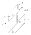
- a holder 6 according to the invention for a surface element 1 (cf. Fig.4 ) of a sun protection or darkening device which is provided for covering a window pane 2 of a motor vehicle with a covering made of a thin covering material 3 and a peripheral frame 4, preferably designed as a tensioning frame, has a receiving space 7 provided for a section of the frame 4, preferably covered with covering material 3, with a receiving opening 8, which is delimited by a base 9 ( Fig.1 ).
- the holder has an insertion element 11 pointing away from the base 9, the end 12 of which is remote from the base 9 and is designed in the form of a hook and which has a contact surface 13 on a side facing the window pane 2, the base having a support area 14 which is arranged on a side of the base 9 which merges into an inner side 16 of the insertion element 11 facing away from the contact surface 13.
- a kind of triangular configuration is evident, which provides optimal support, possibly supplemented with an inner contact surface 17 of the plug-in element.
- the inner side 16 of the insertion element 11 forms the inner contact surface 17, which is particularly objected to by the support area 14 ( Fig.2 ).
- At least one web 19 is arranged on the inner side 16, which forms a hook with the further insertion element 11, by means of which the insertion element 11 can be adapted to different cladding designs.
- the lower web 19, as well as the upper web 19, can be provided with a notch on the side facing away from the base, which in the form of a one-sided, sufficiently rigid film hinge allows a certain flexibility in the connection of the web to the further insertion element, so that insertion into the Fig.4 area shown, but at the same time also allows folding back into the position shown in the Fig.3 shown position is possible.
- the outer surface of a wall 21 of the receiving space 7 facing the window pane is curved, the thickness of the wall 21 becoming thinner in the direction of the end facing away from the base 9 in order not to contact this end of the wall 21 in situations in which the free end of a window pane 2 runs towards the frame.
- the rounded outer surface of the wall 21 also guides the pane into the desired position.
- the holders 6 shown are designed as extruded profiles and are essentially H-shaped, so that the production of the holders is possible in a simple manner.
- the dashed lines 5 show how the edges would be shaped if the corners were rounded.
- the holder 6 is Fig.4 provided with an odd-shaped design in the cross-sectional shape of the insertion element 11 shown, with the side 18 facing the window pane 2 being concave.
- This takes into account the shape of the window pane seal 10, which tapers downwards in the plane of the figure, and at the same time, due to the tracking contact surface 13, ensures sufficiently high pressure in the end region of the window pane seal 10 in the direction of the support region 14.
- the contact surface is preferably formed over the majority of the area (> 50%) of the side of the insertion element facing the window pane.
- the hook-like end 12 is simultaneously fixed to a panel part 15, which covers a frame 20 of the motor vehicle, this results in a precise positioning of the holder 6 and an almost parallel alignment of the inner walls of the walls 21 and 23 of the receiving space 7 to the window pane 2 in cross section.
- the holder according to the invention and thus the sun protection or darkening device according to the invention can be easily adapted to different vehicle models and types.
Landscapes
- Engineering & Computer Science (AREA)
- Mechanical Engineering (AREA)
- Window Of Vehicle (AREA)
Description
- Die vorliegende Erfindung betrifft einen Halter für ein Flächenelement einer Sonnenschutz- oder Verdunklungsvorrichtung, welches zur Abdeckung einer Fensterscheibe eines Kraftfahrzeugs mit einer Bespannung aus einem dünnen Bespannungsmaterial und einem randseitigen umlaufenden, vorzugsweise als Spannrahmen ausgebildeten Rahmen versehen ist, wobei der Halter einen Rahmen für einen Abschnitt des vorzugsweise mit dem Bespannungsmaterial überdeckten Rahmens vorgesehenen Aufnahmeraum mit einer Aufnahmeöffnung aufweist, der von einer Basis begrenzt wird. Des Weiteren betrifft die Erfindung eine entsprechende Sonnenschutz- oder Verdunklungsvorrichtung.
- Aus dem Markt bekannt sind zur Festlegung entsprechender Flächenelemente von Sonnenschutz- oder Verdunklungsvorrichtungen vorgesehene Halter, deren Basis auf einer Seite einen Aufnahmeraum mit einer Aufnahmeöffnung aufweist, in die der Rahmen eingesteckt werden muss. Auf der dem Aufnahmeraum entgegengesetzten Seite der Basis ist eine Klebeschicht vorhanden. Mit dieser Klebeschicht wird der Halter auf einem Verkleidungs- oder Rahmenteil des Kraftfahrzeugs befestigt. Nachteilig ist hierbei, dass die zu beklebende Fläche oftmals nicht ausreichend vorbehandelt und daher nicht sauber bzw. fettfrei ist. Die Klebeschicht gewährt gerade bei einem aufgeheizten Kraftfahrzeuginnenraum keine ausreichende Haftung. Das Flächenelement der Sonnenschutzvorrichtung ist dann nicht ausreichend befestigt. Weiterhin kommt es vor, dass die Klebeschicht nicht rückstandsfrei entfernt werden kann, was beim Austausch der Halter oder bei Leasingfahrzeugen zu Problemen führen kann.
- Ferner offenbaren die
WO 2015/047137 A2 und dieUS 9,272,605 B1 - Die Befestigung mittels der Gegenstände ist gleichwohl mangelhaft.
- Es ist Aufgabe der vorliegenden Erfindung einen gattungsgemäßen Halter bzw. eine gattungsgemäße Sonnenschutz- oder Verdunklungsvorrichtung hinsichtlich der genannten Probleme zu verbessern.
- Gelöst wird diese Aufgabe durch einen Gegenstand gemäß Anspruch 1 sowie durch einen Gegenstand gemäß Anspruch 9. Vorteilhafte Ausgestaltungen der Erfindung sind den auf den Anspruch 1 rückbezogenen Unteransprüchen sowie der nachfolgenden Beschreibung zu entnehmen.
- Erfindungsgemäß ist vorgesehen, einen gattungsgemäßen Halter dahingehend weiterzubilden, dass er ein von der Basis wegweisendes Einsteckelement aufweist, dessen von der Basis entferntes Ende hakenartig ausgebildet ist und das auf einer der Fensterscheibe zuzuwendenden Seite eine Anlagefläche aufweist, wobei die Basis einen Abstützbereich aufweist, der auf einer Seite der Basis angeordnet ist, die in eine von der Anlagefläche abgewandte Innenseite des Einsteckelements übergeht. Ein solcher Halter kann mit seinem Einsteckelement insbesondere zwischen einer Fensterscheibendichtung und einem Verkleidungs- oder anderen Funktionsteil des Kraftfahrzeugs, vorzugsweise einem Rahmen eingesteckt und dort zunächst aufgrund seines hakenartigen Endes befestigt werden. Über die der Fensterscheibe zuzuwendenden Seite ist eine Anlagefläche für die in der Regel aus einem vergleichsweise harten Kunststoff oder Gummi gefertigte Fensterscheibendichtung gegeben, die den Halter in Richtung des Verkleidungs- oder Funktionsteils des Fahrzeugs drückt. Um nun eine exakte Ausrichtung der Aufnahmeöffnung und des Aufnahmeraums zu gewährleisten, ist auf der Basis ein Abstützbereich vorgesehen, der gemeinsam mit dem hakenartigen Endbereich des Einsteckelements und gegebenenfalls weiteren Bereichen der Innenseite Lager ausbildet, in denen der Halter abgestützt ist. Durch das hakenartige Ende rutscht bei einem hierzu insbesondere entlang des Einsteckelements in Richtung der Basis versetzten Andrücken durch ein Scheibendichtungselement bzw. die Fensterscheibendichtung der Halter nicht aus der Halterung. In Kombination mit dem Abstützbereich ist eine selbst bei hohen Geschwindigkeiten und geöffneten Fenstern wirkungsvolle Halterung des Flächenelements gewährleistet.
- Zusätzlich kann auf der Innenseite eine Innenanlagefläche ausgebildet werden, welche vorzugsweise von dem Abstützbereich beabstandet ist, so dass neben dem oder gemeinsam mit dem hakenartigen Ende des Einsteckelements eine verbesserte Anlage des Halters an dem Verkleidungs- oder weiteren Funktionsteil des Fahrzeugs ermöglicht wird.
- Erfindungsgemäß ist das Einsteckelement im Querschnitt betrachtet ungerade ausgebildet und bezüglich seiner zur Fensterscheibe zuzuwendenden Seite nach außen gebogen, d.h. konkav ausgebildet. Hierdurch wird insbesondere bei einer durch einen im Wesentlichen rechtwinklig an dem Einsteckelement ansetzenden Flansch ausgebildeten Basis erreicht, dass das hakenartige Ende verbessert in die Endposition des Kraftfahrzeugs überführt werden kann. Dies ist insbesondere bei höherwertigen Fahrzeugen von Vorteil, da Beschädigungen beispielsweise am Dichtungsmaterial der Scheibendichtungen minimiert werden. Darüber hinaus kann über diese Form ein Konturverlauf der Dichtung, die in Richtung der Basis relativ oft schmaler wird und ausläuft, nachempfunden werden, so dass der Aufnahmeraum und mithin das Flächenelement dichter an der Fensterscheibe positioniert werden können bei gleichzeitig optimaler Abstützung an dem Fensterrahmen bzw. den zugehörigen Verkleidungs- oder anderen Funktionsteilen des Kraftfahrzeugs. Die Ausrichtung des Aufnahmeraums dicht an der Fensterscheibe führt zu einer optimalen Positionierung des Flächenelements.
- Je nach Ausbildung der Verkleidung kann es vorteilhaft sein, wenn das Einsteckelement mehr als ein einen Haken ausbildenden Steg aufweist, wobei insbesondere zur Unterstützung der Hakenfunktion zwischen dem vorzugsweise am Ende des Einsteckelements angeordneten Steg desselben und der Innenseite ein Winkel ≤ 90° ausgebildet wird.
- Gemäß einer weiteren vorteilhaften Ausbildung der Erfindung ist im Querschnitt die Außenfläche einer zur Fensterscheibe hinzuwendenden Wand des Aufnahmeraums gebogen, wobei die Wand in Richtung des von der Basis abgewandten Endes dünner wird. Somit hebt sich das dünner werdende Ende von etwaigen anliegenden Fensterscheibenflächen ab, was gerade für die Anordnung in den oberen Rahmenbereichen der Fenster vorteilhaft ist, da dann die Fensterscheibe beim Schließen weniger auf das Ende des Halters auffährt.
- Vorteilhafterweise ist der Aufnahmeraum durch an der Basis angeordnete Wände begrenzt, deren einander zugewandte Oberflächen überwiegend parallel zueinander ausgebildet sind. Dies erleichtert ein Entfernen der Rahmenelemente, ohne das der Halter aus dem Lagersitz zwischen Fensterscheibendichtung und Verkleidung od.dgl. herausgezogen wird.
- Insbesondere ist der Halter im Wesentlichen h-förmig ausgebildet, so dass eine einfach zu erläuternde Handhabung der Halterung mit einer eindeutigen Aufnahme und einem klar erkennbaren Einsteckelement geschaffen ist. Eine solche Form ist insbesondere dafür geeignet, den Halter durch ein Strangpressprofil, vorzugsweise aus Kunststoff, auszubilden. Ein solches Profil kann einfach abgelängt werden und mit einfachen Strangpresswerkzeugen hergestellt werden.
- Nach dem Ablängen können Spitzen oder Ecken des Profils an den Wänden des Aufnahmeraums abgekantet oder gerundet werden, um eine Beschädigung des Bespannungsmaterials des Flächenelements zu vermeiden.
- Die eingangs gestellte Aufgabe wird dem ebenfalls durch eine Sonnenschutz- oder Verdunklungsvorrichtung mit einem Flächenelement gelöst, welches zur Abdeckung einer Fensterscheibe eines Kraftfahrzeugs mit einer Bespannung aus einem dünnen Bespannungsmaterials und einem randseitig umlaufenden, vorzugsweise als Spannrahmen ausgebildeten Rahmen versehen ist, wobei diese Sonnenschutz- oder Verdunklungsvorrichtung wenigstens einen Halter, wie er vor- oder nachbeschrieben ist, aufweist.
- Weitere Vorteile und Einzelheiten der Erfindung lassen sich der nachfolgenden Figurenbeschreibung entnehmen. Schematisch dargestellt zeigt
- Fig. 1
- einen erfindungsgemäßen Gegenstand in einer perspektivischen Ansicht,
- Fig. 2
- den Gegenstand nach
Fig. 1 in einem Querschnitt, - Fig. 3
- einen weiteren erfindungsgemäßen Gegenstand in einer perspektivischen Darstellung,
- Fig. 4
- einen Teil der erfindungsgemäßen Sonnenschutz- oder Verdunklungsvorrichtung in einer Einbausituation.
- Einzelne technische Merkmale der nach beschriebenen Ausführungsbeispiele können auch in Kombination mit vorbeschriebenen Ausführungsbeispielen sowie den Merkmalen der unabhängigen Ansprüche und etwaig weiterer Ansprüche zu erfindungsgemäßen Gegenständen kombiniert werden. Sofern sinnvoll, werden funktional gleichwirkende Elemente mit identischen Bezugsziffern versehen.
- Ein erfindungsgemäßer Halter 6 für ein Flächenelement 1 (vgl.
Fig. 4 ) einer Sonnenschutz- oder Verdunklungsvorrichtung, welches zur Abdeckung einer Fensterscheibe 2 eines Kraftfahrzeugs mit einer Bespannung aus einem dünnen Bespannungsmaterial 3 und einem randseitigen umlaufenden, vorzugsweise als Spannrahmen ausgebildeten Rahmen 4 versehen ist, weist einen für einen Abschnitt des vorzugsweise mit Bespannungsmaterial 3 überdeckten Rahmens 4 vorgesehenen Aufnahmeraum 7 mit einer Aufnahmeöffnung 8 aufweist, der von einer Basis 9 begrenzt wird (Fig. 1 ). Der Halter weist ein von der Basis 9 weg weisendes Einsteckelement 11 auf, dessen von der Basis 9 entferntes Ende 12 hakenartig ausgebildet ist und das auf einer der Fensterscheibe 2 zuzuwendenden Seite eine Anlagefläche 13 aufweist, wobei die Basis einen Abstützbereich 14 aufweist, der auf einer Seite der Basis 9 angeordnet ist, die in eine von der Anlagefläche 13 abgewandte Innenseite 16 des Einsteckelements 11 übergeht. Durch diese insbesondere auch in derFig. 2 offenbarten Bereiche (Anlagefläche 13, Abstützbereich 14, Ende 12) ist ersichtlich eine Art Dreieckskonfiguration gegeben, die eine optimale Abstützung gegebenenfalls ergänzt mit einer Innenanlagefläche 17 des Einsteckelements ergibt. Dies ist auch in derFig. 4 dargestellt. Die Innenseite 16 des Einsteckelements 11 bildet hier die Innenanlagefläche 17 aus, welches insbesondere von dem Abstützbereich 14 beanstandet ist (Fig. 2 ). - Im Ausführungsbeispiel gemäß der
Fig. 3 sind an der Innenseite 16 wenigstens ein mit dem weiteren Einsteckelement 11 einen Haken ausbildende Stege 19 angeordnet, über die das Einsteckelement 11 an unterschiedliche Verkleidungsausbildungen anpassbar ist. Insbesondere der in derFig. 3 untere Steg 19, wie auch der obere Steg 19 können auf der von der Basis abgewandten Seite mit einem Einschnitt versehen sein, der in Form eines einseitig wirkenden, ausreichend steifen Filmscharniers eine gewisse Flexibilität der Anbindung des Stegs an das weitere Einsteckelement erlaubt, so dass ein Einstecken in den in derFig. 4 dargestellten Bereich erleichtert wird, gleichzeitig jedoch auch ein Zurückklappen in die in derFig. 3 gezeigte Position möglich ist. - Insbesondere in den
Fig. 2 und4 sowie auch in denFig. 1 und3 ist im Querschnitt die Außenfläche einer zur Fensterscheibe hinzuwendenden Wand 21 des Aufnahmeraums 7 gebogen, wobei die Dicke der Wand 21 in Richtung des von der Basis 9 abgewandten Endes dünner wird, um bei Situationen, in denen das freie Ende einer Fensterscheibe 2 zum Rahmen hin läuft, dieses Ende der Wand 21 nicht zu kontaktieren. Durch die gerundete Außenfläche der Wand 21 wird die Scheibe zusätzlich in die gewünschte Position geleitet. - Die dargestellten Halter 6 sind als Strangpressprofile und im Wesentlichen h-förmig ausgebildet, so dass die Erzeugung der Halter auf einfache Weise möglich ist. In der
Fig. 1 dargestellte gestrichelte Linien 5 zeigen, wie der Kantenverlauf im Falle von Abrundungen der Ecken sein würde. - Insbesondere ist der Halter 6 gemäß
Fig. 4 mit einer in der dargestellten Querschnittsform des Einsteckelements 11 ungeraden Ausbildung versehen, wobei die zur Fensterscheibe 2 zuzuwendende Seite 18 konkav ausgebildet ist. Dies trägt dem Verlauf der sich in der Figurenebene nach unten verjüngenden Fensterscheibendichtung 10 Rechnung und sorgt aufgrund der nachgeführten Anlagefläche 13 gleichzeitig für auch im Endbereich der Fensterscheibendichtung 10 ausreichend hohen Druck in Richtung des Abstützbereichs 14. Bevorzugt ist die Anlagefläche über die überwiegende Fläche (> 50 %) der zur Fensterscheibe hinzuwendenden Seite des Einsteckelements ausgebildet. Da gleichzeitig das hakenartige Ende 12 an einem Verkleidungsteil 15, welches einen Rahmen 20 des Kraftfahrzeugs abdeckt, festgelegt ist, ergibt sich eine passgenaue Positionierung des Halters 6 und eine im Querschnitt nahezu parallele Ausrichtung der Innenwände der Wände 21 und 23 des Aufnahmeraums 7 zur Fensterscheibe 2. Durch Variationen in der Krümmung des Einsteckelements 17 (im Querschnitt) sowie der Länge desselben und der Breite der Basis 9 lässt sich der erfindungsgemäße Halter und mithin die erfindungsgemäße Sonnenschutz- oder Verdunklungsvorrichtung auf einfache Weise an verschiedene Fahrzeugmodelle und -typen anpassen.
Claims (8)
- Halter für ein Flächenelement (1) einer Sonnenschutz- oder Verdunklungsvorrichtung, welches zur Abdeckung einer Fensterscheibe (2) eines Kraftfahrzeugs mit einer Bespannung aus einem dünnen Bespannungsmaterial (3) und einem randseitig umlaufenden, vorzugsweise als Spannrahmen ausgebildeten Rahmen (4) versehen ist, wobei der Halter (6) einen für einen Abschnitt des vorzugsweise mit dem Bespannungsmaterial (3) überdeckten Rahmens (4) vorgesehenen Aufnahmeraum (7) mit einer Aufnahmeöffnung (8) aufweist, der von einer Basis (9) begrenzt wird, wobei der Halter (6) ein von der Basis (9) wegweisendes Einsteckelement (11) aufweist, dessen von der Basis (9) entferntes Ende (12) hakenartig ausgebildet ist und das auf einer der Fensterscheibe (2) zuzuwendenden Seite eine Anlagefläche (13) aufweist, wobei die Basis (9) einen Abstützbereich (14) aufweist, der auf einer Seite der Basis (9) angeordnet ist, die in eine von der Anlagefläche (13) abgewandte Innenseite (16) des Einsteckelements (11) übergeht, dadurch gekennzeichnet, dass das Einsteckelement (11) im Querschnitt ungerade und bezüglich seiner zur Fensterscheibe (2) zuzuwendenden Seite (18) konkav ausgebildet ist.
- Halter nach Anspruch 1, dadurch gekennzeichnet, dass die Innenseite (16) eine Innenanlagefläche (17) ausbildet, welche insbesondere von dem Abstützbereich (14) beabstandet ist.
- Halter nach einem der vorhergehenden Ansprüche, dadurch gekennzeichnet, dass an der Innenseite (16) wenigstens ein mit dem weiteren Einsteckelement (11) einen Haken ausbildender Steg (19) angeordnet ist.
- Halter nach einem der vorhergehenden Ansprüche, dadurch gekennzeichnet, dass im Querschnitt die Außenfläche einer zur Fensterscheibe hinzuwendenden Wand (21) des Aufnahmeraums (7) gebogen und die Wand (21) in Richtung des von der Basis (9) abgewandten Endes (22) dünner wird.
- Halter nach einem der vorhergehenden Ansprüche, dadurch gekennzeichnet, dass der Aufnahmeraum (7) durch an der Basis (9) angeordnete Wände (21,23) begrenzt ist, deren einander zugewandte Oberfläche überwiegend parallel zueinander ausgebildet sind.
- Halter nach einem der vorhergehenden Ansprüche, dadurch gekennzeichnet, dass der Halter (6) im Querschnitt im Wesentlichen h-förmig ausgebildet ist.
- Halter nach Anspruch 6, dadurch gekennzeichnet, dass der Halter (6) durch ein Strangpressprofil ausgebildet wird.
- Sonnenschutz- oder Verdunklungsvorrichtung mit einem Flächenelement (1), welches zur Abdeckung einer Fensterscheibe (2) eines Kraftfahrzeugs mit einer Bespannung aus einem dünnen Bespannungsmaterial (3) und einem randseitig umlaufenden, vorzugsweise als Spannrahmen ausgebildeten Rahmen (4)versehen ist, gekennzeichnet durch wenigstens einen Halter (6) nach einem der vorhergehenden Ansprüche.
Applications Claiming Priority (2)
| Application Number | Priority Date | Filing Date | Title |
|---|---|---|---|
| DE202017104204.9U DE202017104204U1 (de) | 2017-07-14 | 2017-07-14 | Halter für ein Flächenelement einer Sonnenschutz- oder Verdunklungsvorrichtung und Sonnenschutz- oder Verdunklungsvorrichtung |
| PCT/EP2018/068280 WO2019011783A1 (de) | 2017-07-14 | 2018-07-05 | Halter für ein flächenelement einer sonnenschutz- oder verdunklungsvorrichtung und sonnenschutz- oder verdunklungsvorrichtung |
Publications (2)
| Publication Number | Publication Date |
|---|---|
| EP3652008A1 EP3652008A1 (de) | 2020-05-20 |
| EP3652008B1 true EP3652008B1 (de) | 2024-06-26 |
Family
ID=62873335
Family Applications (1)
| Application Number | Title | Priority Date | Filing Date |
|---|---|---|---|
| EP18739506.6A Active EP3652008B1 (de) | 2017-07-14 | 2018-07-05 | Halter für ein flächenelement einer sonnenschutz- oder verdunklungsvorrichtung und sonnenschutz- oder verdunklungsvorrichtung |
Country Status (4)
| Country | Link |
|---|---|
| US (1) | US20200148040A1 (de) |
| EP (1) | EP3652008B1 (de) |
| DE (1) | DE202017104204U1 (de) |
| WO (1) | WO2019011783A1 (de) |
Families Citing this family (1)
| Publication number | Priority date | Publication date | Assignee | Title |
|---|---|---|---|---|
| DE202021103616U1 (de) | 2021-07-05 | 2022-10-27 | Windesa Gmbh | Halter für ein Flächenelement einer Sonnenschutz- oder Verdunkelungsvorrichtung |
Family Cites Families (2)
| Publication number | Priority date | Publication date | Assignee | Title |
|---|---|---|---|---|
| WO2015047137A2 (ru) * | 2013-09-27 | 2015-04-02 | ГРИГОРЬЕВ, Дмитрий Львович | Защитный экран для окна передней двери транспортного средства (варианты), защитный экран для окна задней двери транспортного средства (варианты), защитный экран для ветрового заднего окна транспортного средства (варианты), защитный экран для задней форточки транспортного средства (варианты), зажим-держатель для установки защитного экрана без использования инструмента и удерживающих материалов в оптимальной близости к окну (варианты) |
| US9272605B1 (en) * | 2014-10-01 | 2016-03-01 | Creative & Cooperative International, INC. | Holding structure and vehicle sunshade used thereof |
-
2017
- 2017-07-14 DE DE202017104204.9U patent/DE202017104204U1/de active Active
-
2018
- 2018-07-05 US US16/630,861 patent/US20200148040A1/en not_active Abandoned
- 2018-07-05 WO PCT/EP2018/068280 patent/WO2019011783A1/de not_active Ceased
- 2018-07-05 EP EP18739506.6A patent/EP3652008B1/de active Active
Also Published As
| Publication number | Publication date |
|---|---|
| DE202017104204U1 (de) | 2018-10-17 |
| US20200148040A1 (en) | 2020-05-14 |
| EP3652008A1 (de) | 2020-05-20 |
| WO2019011783A1 (de) | 2019-01-17 |
Similar Documents
| Publication | Publication Date | Title |
|---|---|---|
| EP2352658B1 (de) | Scheibenfassung | |
| DE60036311T3 (de) | Verwendung von verglasung mit einem profiliertem band zu seiner installation in einer öffnung | |
| DE69502109T3 (de) | Dichtungsprofile | |
| DE2734971A1 (de) | Tuerdichtung fuer kraftfahrzeuge | |
| EP2188143B1 (de) | Abdeckleiste | |
| DE19946311A1 (de) | Fahrzeugtür | |
| DE10038200B4 (de) | Fensterdichtung zur Anbringung an einer Kraftfahrzeugtüre | |
| DE102014013772B4 (de) | Fahrzeug mit einer Fahrzeugtür | |
| DE102016110276A1 (de) | Dichtung für eine versenkbare Fensterscheibe eines Fahrzeugtürfensters | |
| DE102010001468B4 (de) | Verfahren zur Herstellung einer Dichtung | |
| EP1956158A2 (de) | Anschlussprofil, insbesondere Putzanschlussprofil | |
| EP3652008B1 (de) | Halter für ein flächenelement einer sonnenschutz- oder verdunklungsvorrichtung und sonnenschutz- oder verdunklungsvorrichtung | |
| EP0421316B1 (de) | Verriegelbares Abdicht- und Füllerprofil, insbesondere für Fenster von Kraftfahrzeugen | |
| DE60311697T2 (de) | Flexible Fensterdichtungsleiste | |
| EP2243650B1 (de) | Blendenanordnung für ein KFZ-Fenster | |
| DE68902754T2 (de) | Dichtleiste fuer den unteren teil einer beweglichen fensterscheibe. | |
| DE9006595U1 (de) | Abdicht- und Führungsvorrichtung für ein eine verschiebbare Fensterscheibe aufweisendes Fenster | |
| DE102009010668A1 (de) | Vorrichtung und Verfahren zum Befestigen eines gummielastischen Dichtprofils, sowie Befestigungselement zur Befestigung des Dichtprofils | |
| EP0155641B1 (de) | Vorrichtung zur Führung und Halterung einer beweglichen Fensterscheibe im Fensterrahmen eines Kraftfahrzeugs | |
| EP3330471B1 (de) | Abdeckleiste zum anbringen an einem bauteil sowie verfahren zum anbringen einer derartigen abdeckleiste an einem bauteil | |
| DE202007004123U1 (de) | Extrudierte Dicht- oder Abschlussleiste | |
| DE102006027697B4 (de) | Dichtband | |
| EP0170870B1 (de) | Verfahren zum Herstellen von Dichtungsprofilleisten | |
| DE3239395A1 (de) | Profilleiste | |
| EP1422095B1 (de) | Fensterschacht-Abdeckvorrichtung |
Legal Events
| Date | Code | Title | Description |
|---|---|---|---|
| STAA | Information on the status of an ep patent application or granted ep patent |
Free format text: STATUS: UNKNOWN |
|
| STAA | Information on the status of an ep patent application or granted ep patent |
Free format text: STATUS: THE INTERNATIONAL PUBLICATION HAS BEEN MADE |
|
| PUAI | Public reference made under article 153(3) epc to a published international application that has entered the european phase |
Free format text: ORIGINAL CODE: 0009012 |
|
| STAA | Information on the status of an ep patent application or granted ep patent |
Free format text: STATUS: REQUEST FOR EXAMINATION WAS MADE |
|
| 17P | Request for examination filed |
Effective date: 20200207 |
|
| AK | Designated contracting states |
Kind code of ref document: A1 Designated state(s): AL AT BE BG CH CY CZ DE DK EE ES FI FR GB GR HR HU IE IS IT LI LT LU LV MC MK MT NL NO PL PT RO RS SE SI SK SM TR |
|
| AX | Request for extension of the european patent |
Extension state: BA ME |
|
| 19U | Interruption of proceedings before grant |
Effective date: 20200806 |
|
| 19W | Proceedings resumed before grant after interruption of proceedings |
Effective date: 20210401 |
|
| STAA | Information on the status of an ep patent application or granted ep patent |
Free format text: STATUS: EXAMINATION IS IN PROGRESS |
|
| DAV | Request for validation of the european patent (deleted) | ||
| DAX | Request for extension of the european patent (deleted) | ||
| 17Q | First examination report despatched |
Effective date: 20221205 |
|
| GRAP | Despatch of communication of intention to grant a patent |
Free format text: ORIGINAL CODE: EPIDOSNIGR1 |
|
| STAA | Information on the status of an ep patent application or granted ep patent |
Free format text: STATUS: GRANT OF PATENT IS INTENDED |
|
| INTG | Intention to grant announced |
Effective date: 20240119 |
|
| GRAS | Grant fee paid |
Free format text: ORIGINAL CODE: EPIDOSNIGR3 |
|
| RIN1 | Information on inventor provided before grant (corrected) |
Inventor name: BORNER, NORBERT |
|
| GRAA | (expected) grant |
Free format text: ORIGINAL CODE: 0009210 |
|
| STAA | Information on the status of an ep patent application or granted ep patent |
Free format text: STATUS: THE PATENT HAS BEEN GRANTED |
|
| AK | Designated contracting states |
Kind code of ref document: B1 Designated state(s): AL AT BE BG CH CY CZ DE DK EE ES FI FR GB GR HR HU IE IS IT LI LT LU LV MC MK MT NL NO PL PT RO RS SE SI SK SM TR |
|
| REG | Reference to a national code |
Ref country code: GB Ref legal event code: FG4D Free format text: NOT ENGLISH |
|
| REG | Reference to a national code |
Ref country code: CH Ref legal event code: EP |
|
| REG | Reference to a national code |
Ref country code: DE Ref legal event code: R096 Ref document number: 502018014777 Country of ref document: DE |
|
| REG | Reference to a national code |
Ref country code: NL Ref legal event code: FP |
|
| PG25 | Lapsed in a contracting state [announced via postgrant information from national office to epo] |
Ref country code: BG Free format text: LAPSE BECAUSE OF FAILURE TO SUBMIT A TRANSLATION OF THE DESCRIPTION OR TO PAY THE FEE WITHIN THE PRESCRIBED TIME-LIMIT Effective date: 20240626 |
|
| PG25 | Lapsed in a contracting state [announced via postgrant information from national office to epo] |
Ref country code: FI Free format text: LAPSE BECAUSE OF FAILURE TO SUBMIT A TRANSLATION OF THE DESCRIPTION OR TO PAY THE FEE WITHIN THE PRESCRIBED TIME-LIMIT Effective date: 20240626 Ref country code: HR Free format text: LAPSE BECAUSE OF FAILURE TO SUBMIT A TRANSLATION OF THE DESCRIPTION OR TO PAY THE FEE WITHIN THE PRESCRIBED TIME-LIMIT Effective date: 20240626 |
|
| REG | Reference to a national code |
Ref country code: LT Ref legal event code: MG9D |
|
| PG25 | Lapsed in a contracting state [announced via postgrant information from national office to epo] |
Ref country code: GR Free format text: LAPSE BECAUSE OF FAILURE TO SUBMIT A TRANSLATION OF THE DESCRIPTION OR TO PAY THE FEE WITHIN THE PRESCRIBED TIME-LIMIT Effective date: 20240927 |
|
| PGFP | Annual fee paid to national office [announced via postgrant information from national office to epo] |
Ref country code: AT Payment date: 20240903 Year of fee payment: 7 |
|
| PG25 | Lapsed in a contracting state [announced via postgrant information from national office to epo] |
Ref country code: LV Free format text: LAPSE BECAUSE OF FAILURE TO SUBMIT A TRANSLATION OF THE DESCRIPTION OR TO PAY THE FEE WITHIN THE PRESCRIBED TIME-LIMIT Effective date: 20240626 |
|
| PG25 | Lapsed in a contracting state [announced via postgrant information from national office to epo] |
Ref country code: NO Free format text: LAPSE BECAUSE OF FAILURE TO SUBMIT A TRANSLATION OF THE DESCRIPTION OR TO PAY THE FEE WITHIN THE PRESCRIBED TIME-LIMIT Effective date: 20240926 Ref country code: LV Free format text: LAPSE BECAUSE OF FAILURE TO SUBMIT A TRANSLATION OF THE DESCRIPTION OR TO PAY THE FEE WITHIN THE PRESCRIBED TIME-LIMIT Effective date: 20240626 Ref country code: HR Free format text: LAPSE BECAUSE OF FAILURE TO SUBMIT A TRANSLATION OF THE DESCRIPTION OR TO PAY THE FEE WITHIN THE PRESCRIBED TIME-LIMIT Effective date: 20240626 Ref country code: GR Free format text: LAPSE BECAUSE OF FAILURE TO SUBMIT A TRANSLATION OF THE DESCRIPTION OR TO PAY THE FEE WITHIN THE PRESCRIBED TIME-LIMIT Effective date: 20240927 Ref country code: FI Free format text: LAPSE BECAUSE OF FAILURE TO SUBMIT A TRANSLATION OF THE DESCRIPTION OR TO PAY THE FEE WITHIN THE PRESCRIBED TIME-LIMIT Effective date: 20240626 Ref country code: BG Free format text: LAPSE BECAUSE OF FAILURE TO SUBMIT A TRANSLATION OF THE DESCRIPTION OR TO PAY THE FEE WITHIN THE PRESCRIBED TIME-LIMIT Effective date: 20240626 Ref country code: RS Free format text: LAPSE BECAUSE OF FAILURE TO SUBMIT A TRANSLATION OF THE DESCRIPTION OR TO PAY THE FEE WITHIN THE PRESCRIBED TIME-LIMIT Effective date: 20240926 |
|
| PG25 | Lapsed in a contracting state [announced via postgrant information from national office to epo] |
Ref country code: PT Free format text: LAPSE BECAUSE OF FAILURE TO SUBMIT A TRANSLATION OF THE DESCRIPTION OR TO PAY THE FEE WITHIN THE PRESCRIBED TIME-LIMIT Effective date: 20241028 |
|
| PG25 | Lapsed in a contracting state [announced via postgrant information from national office to epo] |
Ref country code: PT Free format text: LAPSE BECAUSE OF FAILURE TO SUBMIT A TRANSLATION OF THE DESCRIPTION OR TO PAY THE FEE WITHIN THE PRESCRIBED TIME-LIMIT Effective date: 20241028 |
|
| PG25 | Lapsed in a contracting state [announced via postgrant information from national office to epo] |
Ref country code: PL Free format text: LAPSE BECAUSE OF FAILURE TO SUBMIT A TRANSLATION OF THE DESCRIPTION OR TO PAY THE FEE WITHIN THE PRESCRIBED TIME-LIMIT Effective date: 20240626 |
|
| PG25 | Lapsed in a contracting state [announced via postgrant information from national office to epo] |
Ref country code: EE Free format text: LAPSE BECAUSE OF FAILURE TO SUBMIT A TRANSLATION OF THE DESCRIPTION OR TO PAY THE FEE WITHIN THE PRESCRIBED TIME-LIMIT Effective date: 20240626 |
|
| PG25 | Lapsed in a contracting state [announced via postgrant information from national office to epo] |
Ref country code: IS Free format text: LAPSE BECAUSE OF FAILURE TO SUBMIT A TRANSLATION OF THE DESCRIPTION OR TO PAY THE FEE WITHIN THE PRESCRIBED TIME-LIMIT Effective date: 20241026 |
|
| PG25 | Lapsed in a contracting state [announced via postgrant information from national office to epo] |
Ref country code: CZ Free format text: LAPSE BECAUSE OF FAILURE TO SUBMIT A TRANSLATION OF THE DESCRIPTION OR TO PAY THE FEE WITHIN THE PRESCRIBED TIME-LIMIT Effective date: 20240626 |
|
| PG25 | Lapsed in a contracting state [announced via postgrant information from national office to epo] |
Ref country code: RO Free format text: LAPSE BECAUSE OF FAILURE TO SUBMIT A TRANSLATION OF THE DESCRIPTION OR TO PAY THE FEE WITHIN THE PRESCRIBED TIME-LIMIT Effective date: 20240626 Ref country code: SK Free format text: LAPSE BECAUSE OF FAILURE TO SUBMIT A TRANSLATION OF THE DESCRIPTION OR TO PAY THE FEE WITHIN THE PRESCRIBED TIME-LIMIT Effective date: 20240626 |
|
| PG25 | Lapsed in a contracting state [announced via postgrant information from national office to epo] |
Ref country code: SM Free format text: LAPSE BECAUSE OF FAILURE TO SUBMIT A TRANSLATION OF THE DESCRIPTION OR TO PAY THE FEE WITHIN THE PRESCRIBED TIME-LIMIT Effective date: 20240626 Ref country code: ES Free format text: LAPSE BECAUSE OF FAILURE TO SUBMIT A TRANSLATION OF THE DESCRIPTION OR TO PAY THE FEE WITHIN THE PRESCRIBED TIME-LIMIT Effective date: 20240626 |
|
| PG25 | Lapsed in a contracting state [announced via postgrant information from national office to epo] |
Ref country code: SM Free format text: LAPSE BECAUSE OF FAILURE TO SUBMIT A TRANSLATION OF THE DESCRIPTION OR TO PAY THE FEE WITHIN THE PRESCRIBED TIME-LIMIT Effective date: 20240626 Ref country code: SK Free format text: LAPSE BECAUSE OF FAILURE TO SUBMIT A TRANSLATION OF THE DESCRIPTION OR TO PAY THE FEE WITHIN THE PRESCRIBED TIME-LIMIT Effective date: 20240626 Ref country code: RO Free format text: LAPSE BECAUSE OF FAILURE TO SUBMIT A TRANSLATION OF THE DESCRIPTION OR TO PAY THE FEE WITHIN THE PRESCRIBED TIME-LIMIT Effective date: 20240626 Ref country code: PL Free format text: LAPSE BECAUSE OF FAILURE TO SUBMIT A TRANSLATION OF THE DESCRIPTION OR TO PAY THE FEE WITHIN THE PRESCRIBED TIME-LIMIT Effective date: 20240626 Ref country code: IS Free format text: LAPSE BECAUSE OF FAILURE TO SUBMIT A TRANSLATION OF THE DESCRIPTION OR TO PAY THE FEE WITHIN THE PRESCRIBED TIME-LIMIT Effective date: 20241026 Ref country code: ES Free format text: LAPSE BECAUSE OF FAILURE TO SUBMIT A TRANSLATION OF THE DESCRIPTION OR TO PAY THE FEE WITHIN THE PRESCRIBED TIME-LIMIT Effective date: 20240626 Ref country code: EE Free format text: LAPSE BECAUSE OF FAILURE TO SUBMIT A TRANSLATION OF THE DESCRIPTION OR TO PAY THE FEE WITHIN THE PRESCRIBED TIME-LIMIT Effective date: 20240626 Ref country code: CZ Free format text: LAPSE BECAUSE OF FAILURE TO SUBMIT A TRANSLATION OF THE DESCRIPTION OR TO PAY THE FEE WITHIN THE PRESCRIBED TIME-LIMIT Effective date: 20240626 |
|
| PG25 | Lapsed in a contracting state [announced via postgrant information from national office to epo] |
Ref country code: IT Free format text: LAPSE BECAUSE OF FAILURE TO SUBMIT A TRANSLATION OF THE DESCRIPTION OR TO PAY THE FEE WITHIN THE PRESCRIBED TIME-LIMIT Effective date: 20240626 |
|
| REG | Reference to a national code |
Ref country code: CH Ref legal event code: PL |
|
| PG25 | Lapsed in a contracting state [announced via postgrant information from national office to epo] |
Ref country code: LU Free format text: LAPSE BECAUSE OF NON-PAYMENT OF DUE FEES Effective date: 20240705 |
|
| PG25 | Lapsed in a contracting state [announced via postgrant information from national office to epo] |
Ref country code: MC Free format text: LAPSE BECAUSE OF FAILURE TO SUBMIT A TRANSLATION OF THE DESCRIPTION OR TO PAY THE FEE WITHIN THE PRESCRIBED TIME-LIMIT Effective date: 20240626 |
|
| REG | Reference to a national code |
Ref country code: DE Ref legal event code: R097 Ref document number: 502018014777 Country of ref document: DE |
|
| PG25 | Lapsed in a contracting state [announced via postgrant information from national office to epo] |
Ref country code: MC Free format text: LAPSE BECAUSE OF FAILURE TO SUBMIT A TRANSLATION OF THE DESCRIPTION OR TO PAY THE FEE WITHIN THE PRESCRIBED TIME-LIMIT Effective date: 20240626 Ref country code: LU Free format text: LAPSE BECAUSE OF NON-PAYMENT OF DUE FEES Effective date: 20240705 |
|
| PG25 | Lapsed in a contracting state [announced via postgrant information from national office to epo] |
Ref country code: DK Free format text: LAPSE BECAUSE OF FAILURE TO SUBMIT A TRANSLATION OF THE DESCRIPTION OR TO PAY THE FEE WITHIN THE PRESCRIBED TIME-LIMIT Effective date: 20240626 |
|
| PG25 | Lapsed in a contracting state [announced via postgrant information from national office to epo] |
Ref country code: CH Free format text: LAPSE BECAUSE OF NON-PAYMENT OF DUE FEES Effective date: 20240731 Ref country code: BE Free format text: LAPSE BECAUSE OF NON-PAYMENT OF DUE FEES Effective date: 20240731 |
|
| PLBE | No opposition filed within time limit |
Free format text: ORIGINAL CODE: 0009261 |
|
| STAA | Information on the status of an ep patent application or granted ep patent |
Free format text: STATUS: NO OPPOSITION FILED WITHIN TIME LIMIT |
|
| GBPC | Gb: european patent ceased through non-payment of renewal fee |
Effective date: 20240926 |
|
| 26N | No opposition filed |
Effective date: 20250327 |
|
| REG | Reference to a national code |
Ref country code: BE Ref legal event code: MM Effective date: 20240731 |
|
| PG25 | Lapsed in a contracting state [announced via postgrant information from national office to epo] |
Ref country code: GB Free format text: LAPSE BECAUSE OF NON-PAYMENT OF DUE FEES Effective date: 20240926 |
|
| PG25 | Lapsed in a contracting state [announced via postgrant information from national office to epo] |
Ref country code: FR Free format text: LAPSE BECAUSE OF NON-PAYMENT OF DUE FEES Effective date: 20240826 |
|
| PG25 | Lapsed in a contracting state [announced via postgrant information from national office to epo] |
Ref country code: IE Free format text: LAPSE BECAUSE OF NON-PAYMENT OF DUE FEES Effective date: 20240705 |
|
| PGFP | Annual fee paid to national office [announced via postgrant information from national office to epo] |
Ref country code: NL Payment date: 20250723 Year of fee payment: 8 |
|
| PG25 | Lapsed in a contracting state [announced via postgrant information from national office to epo] |
Ref country code: SE Free format text: LAPSE BECAUSE OF FAILURE TO SUBMIT A TRANSLATION OF THE DESCRIPTION OR TO PAY THE FEE WITHIN THE PRESCRIBED TIME-LIMIT Effective date: 20240626 |
|
| PGFP | Annual fee paid to national office [announced via postgrant information from national office to epo] |
Ref country code: DE Payment date: 20250520 Year of fee payment: 8 |
|
| PG25 | Lapsed in a contracting state [announced via postgrant information from national office to epo] |
Ref country code: CY Free format text: LAPSE BECAUSE OF FAILURE TO SUBMIT A TRANSLATION OF THE DESCRIPTION OR TO PAY THE FEE WITHIN THE PRESCRIBED TIME-LIMIT; INVALID AB INITIO Effective date: 20180705 |
|
| PG25 | Lapsed in a contracting state [announced via postgrant information from national office to epo] |
Ref country code: HU Free format text: LAPSE BECAUSE OF FAILURE TO SUBMIT A TRANSLATION OF THE DESCRIPTION OR TO PAY THE FEE WITHIN THE PRESCRIBED TIME-LIMIT; INVALID AB INITIO Effective date: 20180705 |
|
| REG | Reference to a national code |
Ref country code: AT Ref legal event code: MM01 Ref document number: 1697430 Country of ref document: AT Kind code of ref document: T Effective date: 20250705 |
|
| PG25 | Lapsed in a contracting state [announced via postgrant information from national office to epo] |
Ref country code: AT Free format text: LAPSE BECAUSE OF NON-PAYMENT OF DUE FEES Effective date: 20250705 |