EP3650776A1 - Air-conditioner indoor unit - Google Patents
Air-conditioner indoor unit Download PDFInfo
- Publication number
- EP3650776A1 EP3650776A1 EP17916558.4A EP17916558A EP3650776A1 EP 3650776 A1 EP3650776 A1 EP 3650776A1 EP 17916558 A EP17916558 A EP 17916558A EP 3650776 A1 EP3650776 A1 EP 3650776A1
- Authority
- EP
- European Patent Office
- Prior art keywords
- panel
- face frame
- indoor unit
- conditioner indoor
- clamps
- Prior art date
- Legal status (The legal status is an assumption and is not a legal conclusion. Google has not performed a legal analysis and makes no representation as to the accuracy of the status listed.)
- Granted
Links
Images




Classifications
-
- F—MECHANICAL ENGINEERING; LIGHTING; HEATING; WEAPONS; BLASTING
- F24—HEATING; RANGES; VENTILATING
- F24F—AIR-CONDITIONING; AIR-HUMIDIFICATION; VENTILATION; USE OF AIR CURRENTS FOR SCREENING
- F24F13/00—Details common to, or for air-conditioning, air-humidification, ventilation or use of air currents for screening
- F24F13/02—Ducting arrangements
-
- F—MECHANICAL ENGINEERING; LIGHTING; HEATING; WEAPONS; BLASTING
- F24—HEATING; RANGES; VENTILATING
- F24F—AIR-CONDITIONING; AIR-HUMIDIFICATION; VENTILATION; USE OF AIR CURRENTS FOR SCREENING
- F24F1/00—Room units for air-conditioning, e.g. separate or self-contained units or units receiving primary air from a central station
- F24F1/0007—Indoor units, e.g. fan coil units
-
- F—MECHANICAL ENGINEERING; LIGHTING; HEATING; WEAPONS; BLASTING
- F24—HEATING; RANGES; VENTILATING
- F24F—AIR-CONDITIONING; AIR-HUMIDIFICATION; VENTILATION; USE OF AIR CURRENTS FOR SCREENING
- F24F1/00—Room units for air-conditioning, e.g. separate or self-contained units or units receiving primary air from a central station
- F24F1/0007—Indoor units, e.g. fan coil units
- F24F1/0011—Indoor units, e.g. fan coil units characterised by air outlets
-
- F—MECHANICAL ENGINEERING; LIGHTING; HEATING; WEAPONS; BLASTING
- F24—HEATING; RANGES; VENTILATING
- F24F—AIR-CONDITIONING; AIR-HUMIDIFICATION; VENTILATION; USE OF AIR CURRENTS FOR SCREENING
- F24F13/00—Details common to, or for air-conditioning, air-humidification, ventilation or use of air currents for screening
-
- F—MECHANICAL ENGINEERING; LIGHTING; HEATING; WEAPONS; BLASTING
- F24—HEATING; RANGES; VENTILATING
- F24F—AIR-CONDITIONING; AIR-HUMIDIFICATION; VENTILATION; USE OF AIR CURRENTS FOR SCREENING
- F24F13/00—Details common to, or for air-conditioning, air-humidification, ventilation or use of air currents for screening
- F24F13/08—Air-flow control members, e.g. louvres, grilles, flaps or guide plates
- F24F13/082—Grilles, registers or guards
-
- F—MECHANICAL ENGINEERING; LIGHTING; HEATING; WEAPONS; BLASTING
- F24—HEATING; RANGES; VENTILATING
- F24F—AIR-CONDITIONING; AIR-HUMIDIFICATION; VENTILATION; USE OF AIR CURRENTS FOR SCREENING
- F24F13/00—Details common to, or for air-conditioning, air-humidification, ventilation or use of air currents for screening
- F24F13/08—Air-flow control members, e.g. louvres, grilles, flaps or guide plates
- F24F13/082—Grilles, registers or guards
- F24F13/085—Grilles, registers or guards including an air filter
-
- F—MECHANICAL ENGINEERING; LIGHTING; HEATING; WEAPONS; BLASTING
- F24—HEATING; RANGES; VENTILATING
- F24F—AIR-CONDITIONING; AIR-HUMIDIFICATION; VENTILATION; USE OF AIR CURRENTS FOR SCREENING
- F24F13/00—Details common to, or for air-conditioning, air-humidification, ventilation or use of air currents for screening
- F24F13/20—Casings or covers
-
- F—MECHANICAL ENGINEERING; LIGHTING; HEATING; WEAPONS; BLASTING
- F24—HEATING; RANGES; VENTILATING
- F24F—AIR-CONDITIONING; AIR-HUMIDIFICATION; VENTILATION; USE OF AIR CURRENTS FOR SCREENING
- F24F13/00—Details common to, or for air-conditioning, air-humidification, ventilation or use of air currents for screening
- F24F13/22—Means for preventing condensation or evacuating condensate
- F24F13/222—Means for preventing condensation or evacuating condensate for evacuating condensate
-
- F—MECHANICAL ENGINEERING; LIGHTING; HEATING; WEAPONS; BLASTING
- F24—HEATING; RANGES; VENTILATING
- F24F—AIR-CONDITIONING; AIR-HUMIDIFICATION; VENTILATION; USE OF AIR CURRENTS FOR SCREENING
- F24F13/00—Details common to, or for air-conditioning, air-humidification, ventilation or use of air currents for screening
- F24F13/28—Arrangement or mounting of filters
-
- F—MECHANICAL ENGINEERING; LIGHTING; HEATING; WEAPONS; BLASTING
- F24—HEATING; RANGES; VENTILATING
- F24F—AIR-CONDITIONING; AIR-HUMIDIFICATION; VENTILATION; USE OF AIR CURRENTS FOR SCREENING
- F24F13/00—Details common to, or for air-conditioning, air-humidification, ventilation or use of air currents for screening
- F24F13/32—Supports for air-conditioning, air-humidification or ventilation units
Definitions
- the present disclosure relates to the technical field of air conditioners, in particular to air conditioner indoor unit.
- the main purpose of the present disclosure is to provide an air conditioner indoor unit, which aims to improve the disassembly and assembly convenience of the air conditioner indoor unit and facilitate deep cleaning of the air conditioner indoor unit.
- the air conditioner indoor unit including: a chassis, an air duct assembly detachably connected with the chassis; a face frame forming an installation opening and a detachment opening that is configured to allow the air duct assembly to pass through; a grille assembly including a grille member detachably installed at the installation opening and a filter arranged on the grille member; a first panel configured to open or close the detachment opening, and including an air outlet communicated with the air duct assembly; and a second panel configured to cooperate with the first panel to cover a surface of the face frame.
- the first panel is clamped with the face frame.
- the first panel cooperates with the second panel to cover a front side of the face frame, the second panel being positioned above the first panel; and a left end and a right end of the first panel are detachably clamped with the face frame.
- one end of the first panel is rotatably connected with the face frame, and another end of the first panel is movable in a direction away from the face frame.
- an upper end of the second panel is rotatably connected with the face frame, and a lower end of the second panel is movable in a direction away from the face frame.
- the first panel includes a plurality of clamps protrudes from an inner side of the first panel
- the face frame includes a plurality of clamping holes formed at a front side of the face frame and configured to fit with the clamps
- the face frame includes a plurality of clamps protrudes from a front side of the face frame
- the first panel includes a plurality of clamping holes formed on the inner side surface of the first panel and configured to fit with the clamps.
- the plurality of clamps includes: one or more clamps at the inner side of the left end of the first panel, and one or more clamps at the inner side of the right end of the first panel.
- the plurality of the clamps includes: two first clamps oppositely arranged at on the inner side of a left end of the first panel and spaced apart from each other, and two first clamps oppositely arranged at the inner side of a right end of the first panel and spaced apart from each other;
- each of the two fist clamps and the two second clamps comprises a fastening-protruding portion extending along an up-down direction at a free end of the clamps; and the fastening-protruding portions of the two first clamps extend in opposite directions, and the fastening-protruding portions of the two second clamps extend in opposite directions.
- the second panel and the face frame are integrally formed; or the second panel is rotatably connected with the face frame at one end of the second panel, and is openable relatively away from the face frame at another end of the second panel.
- the grille member and the filter are integrally formed.
- the air conditioner indoor unit further includes an air guiding assembly, at the first panel.
- the air duct assembly includes a volute, the volute including: a first sliding protrusion structure at a left end of the volute, and a second sliding protrusion structure at a right end of the volute;
- the chassis includes: a first side fixing portion arranged at a left end of the chassis, and a second side fixing portion arranged at a right end of the chassis, the first side fixing portions including a first sliding groove structure at a side facing to the second side fixing portions, the second side fixing portions including a second sliding groove structure at a side facing to the first side fixing portions; the first sliding protrusion structure is engaged with the first sliding groove structure, and the second sliding protrusion structure is engaged with the second sliding groove structure.
- the air duct assembly further includes the air duct assembly further includes: a front water receiving plate, and a rear water receiving plate, the front water receiving plate and the rear water receiving plate both formed at an upper part of the volute and integrally formed with the volute.
- the air duct assembly detachably connected to the chassis can be conveniently disassembled from the detachment opening. This provides great convenience for deep cleaning of the air duct, the heat exchanger and other related components.
- the face frame is provided with an installation opening, and the grille member on which the filter is installed is detachably connected to the installation opening, the filter can also be conveniently disassembled for cleaning.
- directional indications such as up, down, left, right, front, back, etc.
- the directional indications are only used to explain the relative positional relationship and movement between the components in a certain posture (as shown in the drawings), and if the specific posture changes, the directional indications will change accordingly.
- first and second are used for descriptive purposes only and cannot be understood as indicating or implying their relative importance or implicitly indicating the number of indicated technical features.
- features defining “first” and “second” may explicitly or implicitly include at least one of the features.
- technical solutions between the various embodiments may be combined with each other, but must be based on what one of ordinary skill in the art can achieve. When the combination of technical solutions is contradictory or impossible to achieve, it should be considered that the combination of such technical solutions does not exist and is not within the protection scope required by the present disclosure.
- the present disclosure provides an air conditioner indoor unit.
- the air conditioner indoor unit is specifically a wall-mounted air conditioner indoor unit.
- the air conditioning indoor unit comprises a chassis 1, an air duct assembly (not labeled), a face frame 3, a screen assembly (not labeled), a first panel 5 and a second panel 6.
- the air duct assembly is detachably connected with the chassis 1.
- the face frame 3 is provided with an installation opening (not labeled) and a detachment opening 32 for disassemble the air duct assembly.
- the grille assembly includes a grille member 41 detachably mounted on the installation opening and a filter (not shown) provided on the grille member 41.
- the first panel 5 is configured to open or close the detachment opening 32, and the first panel 5 is provided with an air outlet 51 connected with the air duct fromed by the air duct assembly.
- the second panel 6 and the first panel 5 are engaged to cover a surface of the face frame 3.
- the face frame 3 includes an upper bracket 33, a lower frame 34, and two opposite side connectors 35 located between the upper bracket 33 and the lower frame 34.
- the installation opening is formed between the upper bracket 33 and the lower frame 34.
- the detachment opening 32 is formed in the lower frame 34.
- the grille member 41 is detachably installed at the upper bracket 33.
- the air duct assembly detachably connected to the chassis 1 can be conveniently disassembled from the detachment opening 32.
- This provides great convenience for deep cleaning of the air duct, the heat exchanger and other related components.
- the face frame 3 is provided with an installation opening, and the grille member 41 on which the filter is installed is detachably connected to the installation opening, the filter can also be conveniently disassembled for cleaning.
- the synergistic action of the aforementioned aspects improves the disassembly and assembly convenience of the air conditioner indoor unit, and facilitates the thorough and deep cleaning of the air conditioner indoor unit. This may bring benefits in reducing the potential health hazard coming from the air conditioner indoor unit.
- the first panel 5 is optionally detachably fastened with the face frame 3.
- the first panel 5 and the second panel 6 cooperatively cover the front side of the face frame 3, and the second panel 6 is located above the first panel 5.
- the left and right ends of the first panel 5 are detachably fastened with the face frame 3.
- the first panel 5 can be detachably clamped with the face frame 3 at the upper and lower ends or the peripheral edges of the first panel 5.
- the arrangement of the first panel 5 detachably clamped with the face frame 3 at the left and right ends of the first panel 5, can simplify the structure and avoid interference in the disassembly of the air duct assembly.
- the inner side of the first panel 5 is protruded with a plurality of fasteners 52, and the front side of the face frame 3 is provided with clamping holes 36 into which the fasteners 52 are fastened.
- the engagement of the first panel 5 and the face frame 3 can be implemented by fastening the fasteners 52 into the corresponding clamping holes 36.
- the fasteners 52 that only need to be separated from the clamping holes 36.
- a plurality of fasteners 52 are provided and are respectively arranged on the inner sides at the left and right ends of the first panel 5.
- the lower frame 34 is extending inward at its left and right edges to form a protruding plate 341.
- the protruding plate 341 is provided with clamping holes 36, i.e. the clamping holes 36 are arranged on the left and right sides of the detachment opening 32 to avoid interference to the disassembly of the air duct assembly.
- the present disclosure is not limited to the aforementioned arrangement.
- the fastener 52 may also be provided on the front side of the face frame 3. Accordingly, the clamping hole 36 is provided on the inner side of the first panel 5.
- the fastener 52 is not limited to the clamping hole 36, and may be of a structure such as a clamping seat.
- the first panel 5 are respectively provided with two fasteners 52 that are spaced on the inner sides of the left and right ends of the first panel 5.
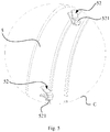
- Each of the fasteners 52 includes a fastening and protruding portion 521 extending along an up-down direction at a free end of the fasteners 52, and the fastening and protruding portions 521 at a same end are extending in an opposite direction. As shown in Fig. 5 , the two fasteners 52 located on the same side are spaced in the up-down direction.
- the fastener 52 on the upper side is disposed adjacent to the upper end of the first panel 5, and the fastening and protruding portion 521 is extending upward. While the fastening and protruding portion 521 of the fastener 52 located on the lower side extends downward. As such, when the fastener 52 is inserted into the clamping hole 36, the fastening and protruding portion 521 is abutted against the inner side of the edge of the clamping hole 36, thereby realizing the limit connection in the front-rear direction to the first panel 5. While the arrangement of the fastening and protruding portions 521 of the upper and lower fasteners 52 in opposite extending directions can limit the first panel 5 in the up-down direction.
- the air conditioner indoor unit further includes an air guiding assembly 8 installed on the first panel 5.
- the air guiding assembly 8 includes an air guiding plate 82 and a drive motor 81 for driving the air guiding plate 82 to rotate.
- the air guiding plate 82 is internally arranged in the air outlet 51, and the left and right ends of the air guiding plate 82 are respectively rotatably connected with the first panel 5, and one end of the air guiding plate 82 is connected with the drive motor 81.
- the drive motor 81 is fixed to the inner side of the first panel 5 and located at one side of the air outlet 51 in the left-right direction. It can be appreciated that when the first panel 5 is opened relative to the face frame 3 to expose the detachment opening 32, the air guiding assembly 8 installed on the first panel 5 is also opened accordingly.
- the air guiding assembly 82 and the like can be conveniently cleaned.
- the air duct assembly includes a volute 21, the chassis 1 is provided with side fixing portions 11 at the respective left and right ends of the chassis 1.
- the two opposite sides of the two side fixing portion 11 are respectively provided with sliding groove structures.
- the volute 21 are respectively provided with sliding convex structures 211 at the left and right ends of the volute 21, to slidably engage with the sliding groove structures.
- the air duct assembly can slide out of the chassis 1 very conveniently.
- the present disclosure is not limited to the aforementioned arrangement, and the sliding protrusion structures 211 may be respectively provided at the two side fixing portions 11, and correspondingly, the sliding groove structures are provided at the left and right side ends of the volute 21.
- the volute 21 are provided with two side plates at the left and right ends of the volute 21, the outer sides of which is protruded outward to form a sliding block 211a.
- the periphery of the free end of the sliding block 211a is extended outward along the circumferential direction to form a limiting flange 211b.
- the inner side of the side fixing part 11 protrudes inwards along the left-right direction to form a connecting part 111, which is provided with a sliding groove 112 with an upper opening and its length extending along the front-back direction.
- the bottom end of the sliding block 211a is in sliding fit with the sliding groove 112, and the inner side of the limiting flange 211b is in sliding fit with the surface of the connecting part 111 facing the fixing part 11 on the other side.
- the sliding block 211a is preferably hollow to save material.
- the air duct assembly further comprises a front water receiving plate 22 and a rear water receiving plate (not shown), in which the front water receiving plate 22 and the rear water receiving plate are both formed on the upper part of the volute 21 and are integrally formed with the volute 21.
- the front water receiving plate 22 and the rear water receiving plate integrated with the volute 21 can also be separated from the chassis 1, thereby facilitating cleaning of these components.
- the fan wheel 24 of the air conditioner indoor unit and the fan wheel motor 25 for driving the fan wheel 24 are also arranged at the upper part of the volute 21 and are positioned between the front water receiving plate 22 and the rear water receiving plate. The fan wheel 24 and the fan wheel motor 25 can also be disassembled together with air duct assembly, thus facilitating the maintenance and cleaning of these two components.
- the first panel 5 is detachably fastened with the face frame 3.
- the second panel 6 is fixedly connected with the face frame 3 and is optionally integrally arranged.
- the installation opening of the face frame 3 is extended from the front side of the face frame 3 to the upper bracket 33, and the installation opening at the upper bracket 33 is the air inlet of the air conditioner indoor unit in a normal sense.
- the grille member 41 is internally provided with the air inlet and detachably clamped with the air inlet.
- the grille member is provided with a plurality of fixing fasteners for clamping with the upper bracket.
- the fixing fasteners are optionally respectively arranged on the left and right sides of the grille member.
- the filter is arranged on the grille member 41 and can be detached with the grille member 41.
- the grille member 41 is optionally integrally formed with the filter.
- the technical solution of the present disclosure is not limited to the aforementioned arrangement.
- the second panel 6 located above the first panel 5 can be rotatably open relative to the face frame 3.
- the upper end of the second panel 6 is rotatably connected with the face frame 3, and the lower end thereof can be open away from the opening of the face frame 3.
- the opening or closing of the opening 32 of the first panel 5 can also be realized by rotation, i.e., one end of the first panel 5 is rotatably connected with the face frame 3, and the other end can be relatively opened away from the face frame 3.
- the upper end of the first panel 5 is rotatably connected with the face frame 3, and the lower end can be opened relatively away from the face frame 3.
- the second panel 6 is fixedly connected with the face frame 3 and is may be optionally arranged of an integral structure.
- the filter is arranged on the grille member 41 and can be detached along with the grille member 41. While in the fourth embodiment as shown in Fig.
- the upper end of the second panel 6 is rotatably connected with the face frame 3, and its lower end can be opened relatively away from the face frame 3. It should also be noted that based on the technical solution of the present disclosure, the removal of the filter can be performed before the first panel 5 is opened.
Landscapes
- Engineering & Computer Science (AREA)
- Chemical & Material Sciences (AREA)
- Combustion & Propulsion (AREA)
- Mechanical Engineering (AREA)
- General Engineering & Computer Science (AREA)
- Air Filters, Heat-Exchange Apparatuses, And Housings Of Air-Conditioning Units (AREA)
- Devices For Blowing Cold Air, Devices For Blowing Warm Air, And Means For Preventing Water Condensation In Air Conditioning Units (AREA)
Abstract
Description
- The present disclosure relates to the technical field of air conditioners, in particular to air conditioner indoor unit.
- With the popularization of air conditioner, users have been increasingly concerned about the health problems caused by air conditioning. Regarding split-type indoor units of air conditioners, indoor air typically is blown back into the room passing in sequence through a filter, an evaporator, a fan wheel, an air duct and the like. If the above parts are not cleaned in time or thoroughly, bacteria and even mildew are easily grown, contaminating the cold air blown out by the air conditioner. However, in the assembly of the related indoor air conditioners, only the front panel covering the filter installation opening can be opened at a certain angle to take out the filter for cleaning. Other components, especially the air duct assembly, cannot be removed and cleaned by the user, due to the assembling complication. This makes the user using these indoor air conditioner suffer from health risks.
- The main purpose of the present disclosure is to provide an air conditioner indoor unit, which aims to improve the disassembly and assembly convenience of the air conditioner indoor unit and facilitate deep cleaning of the air conditioner indoor unit.
- In order to achieve the above objective, the air conditioner indoor unit provided by the invention including: a chassis, an air duct assembly detachably connected with the chassis; a face frame forming an installation opening and a detachment opening that is configured to allow the air duct assembly to pass through; a grille assembly including a grille member detachably installed at the installation opening and a filter arranged on the grille member; a first panel configured to open or close the detachment opening, and including an air outlet communicated with the air duct assembly; and a second panel configured to cooperate with the first panel to cover a surface of the face frame.
- Preferably, the first panel is clamped with the face frame.
- Preferably, the first panel cooperates with the second panel to cover a front side of the face frame, the second panel being positioned above the first panel; and a left end and a right end of the first panel are detachably clamped with the face frame.
- Preferably, one end of the first panel is rotatably connected with the face frame, and another end of the first panel is movable in a direction away from the face frame.
- Preferably, an upper end of the second panel is rotatably connected with the face frame, and a lower end of the second panel is movable in a direction away from the face frame.
- Preferably, the first panel includes a plurality of clamps protrudes from an inner side of the first panel, and the face frame includes a plurality of clamping holes formed at a front side of the face frame and configured to fit with the clamps;
- Preferably, the face frame includes a plurality of clamps protrudes from a front side of the face frame, and the first panel includes a plurality of clamping holes formed on the inner side surface of the first panel and configured to fit with the clamps.
- Preferably, the plurality of clamps includes: one or more clamps at the inner side of the left end of the first panel, and one or more clamps at the inner side of the right end of the first panel.
- Preferably, the plurality of the clamps includes: two first clamps oppositely arranged at on the inner side of a left end of the first panel and spaced apart from each other, and two first clamps oppositely arranged at the inner side of a right end of the first panel and spaced apart from each other;
- each of the two fist clamps and the two second clamps comprises a fastening-protruding portion extending along an up-down direction at a free end of the clamps; and the fastening-protruding portions of the two first clamps extend in opposite directions, and the fastening-protruding portions of the two second clamps extend in opposite directions.
- Preferably, the second panel and the face frame are integrally formed; or the second panel is rotatably connected with the face frame at one end of the second panel, and is openable relatively away from the face frame at another end of the second panel.
- Preferably, the grille member and the filter are integrally formed.
- Preferably, the air conditioner indoor unit further includes an air guiding assembly, at the first panel.
- Preferably, the air duct assembly includes a volute, the volute including: a first sliding protrusion structure at a left end of the volute, and a second sliding protrusion structure at a right end of the volute; the chassis includes: a first side fixing portion arranged at a left end of the chassis, and a second side fixing portion arranged at a right end of the chassis, the first side fixing portions including a first sliding groove structure at a side facing to the second side fixing portions, the second side fixing portions including a second sliding groove structure at a side facing to the first side fixing portions; the first sliding protrusion structure is engaged with the first sliding groove structure, and the second sliding protrusion structure is engaged with the second sliding groove structure.
- Preferably, the air duct assembly further includes the air duct assembly further includes: a front water receiving plate, and a rear water receiving plate, the front water receiving plate and the rear water receiving plate both formed at an upper part of the volute and integrally formed with the volute.
- In the technical solution of the air conditioner indoor unit of the invention, n one aspect, since the first panel can be opened relative to the face frame to expose the detachment opening, the air duct assembly detachably connected to the chassis can be conveniently disassembled from the detachment opening. This provides great convenience for deep cleaning of the air duct, the heat exchanger and other related components. In another aspect, since the face frame is provided with an installation opening, and the grille member on which the filter is installed is detachably connected to the installation opening, the filter can also be conveniently disassembled for cleaning. The synergistic action of the aforementioned aspects improves the disassembly and assembly convenience of the air conditioner indoor unit, and facilitates the thorough and deep cleaning of the air conditioner indoor unit. This may bring benefits in reducing the potential health hazard coming from the air conditioner indoor unit.
- In order to explain the embodiment of the present disclosure or the technical solution of the prior art more clearly, the following will briefly introduce the drawings necessary in the description of the embodiments or the prior art. Obviously, the drawings in the following description are only some embodiments of the present disclosure. For those ordinary skill in the art, other drawings can be obtained according to the structure shown in these drawings without any creative effort.
-
Fig. 1 is an exploded view of an air conditioner indoor unit according to a first embodiment of the present disclosure; -
Fig. 2 is an enlarged schematic view at portion A inFig. 1 ; -
Fig. 3 is an enlarged schematic view at position B inFig. 1 ; -
Fig. 4 is a schematic structural view of the first panel inFig. 1 ; -
Fig. 5 is an enlarged schematic view at portion C inFig. 4 ; -
Fig. 6 is an exploded view of an air conditioner indoor unit according to a second embodiment of the present disclosure; -
Fig. 7 is an exploded view of an air conditioner indoor unit according to a third embodiment of the present disclosure; -
Fig. 8 is an exploded view of an air conditioner indoor unit according to a fourth embodiment of the present disclosure. -
Reference Numeral Name Reference Numeral Name 1 Chassis 11 Side fixing portion 111 Connecting portion 112 Sliding groove 21 Volute 22 Front water receiving tray 211 Sliding protrusion structure 211a Sliding block 211b Limiting flange 24 Fan wheel 25 Fan wheel motor 3 Face frame 32 Detaching mouth 33 Upper support 34 Lower frame 35 Side connector 41 Grille member 5 First panel 6 Second panel 341 Protruding plate 36 clamping hole 51 Air outlet 8 Air guiding assembly 81 Drive motor 82 Air guiding plate 52 Fastener 521 Fastening and protruding portion - The implementation, functional features and advantages of the present disclosure will be further described with reference to the accompanying drawings with the embodiments.
- As following, the technical solution in the embodiments of the present disclosure will be described clearly and completely with reference to the drawings in the embodiment of the present disclosure. Obviously, the described embodiment is only a part of the embodiment of the present disclosure, not all of the embodiments. Based on the embodiments in the present disclosure, all other embodiments perceived by those ordinary skills in the art without creative effort should be fallen within the protection scope of the present disclosure.
- It should be noted that if directional indications (such as up, down, left, right, front, back, etc.) are involved in the embodiments of the present disclosure, the directional indications are only used to explain the relative positional relationship and movement between the components in a certain posture (as shown in the drawings), and if the specific posture changes, the directional indications will change accordingly.
- In addition, if there are descriptions of "first" and "second" in the embodiments of this application, the descriptions of "first" and "second" are used for descriptive purposes only and cannot be understood as indicating or implying their relative importance or implicitly indicating the number of indicated technical features. Thus, features defining "first" and "second" may explicitly or implicitly include at least one of the features. In addition, the technical solutions between the various embodiments may be combined with each other, but must be based on what one of ordinary skill in the art can achieve. When the combination of technical solutions is contradictory or impossible to achieve, it should be considered that the combination of such technical solutions does not exist and is not within the protection scope required by the present disclosure.
- The present disclosure provides an air conditioner indoor unit.
- Referring to
Fig. 1 , in a first embodiment of the present disclosure, the air conditioner indoor unit is specifically a wall-mounted air conditioner indoor unit. The air conditioning indoor unit comprises achassis 1, an air duct assembly (not labeled), aface frame 3, a screen assembly (not labeled), afirst panel 5 and asecond panel 6. The air duct assembly is detachably connected with thechassis 1. Theface frame 3 is provided with an installation opening (not labeled) and a detachment opening 32 for disassemble the air duct assembly. The grille assembly includes agrille member 41 detachably mounted on the installation opening and a filter (not shown) provided on thegrille member 41. Thefirst panel 5 is configured to open or close the detachment opening 32, and thefirst panel 5 is provided with anair outlet 51 connected with the air duct fromed by the air duct assembly. Thesecond panel 6 and thefirst panel 5 are engaged to cover a surface of theface frame 3. - It should be appreciated that in the present embodiment, the
face frame 3 includes anupper bracket 33, alower frame 34, and twoopposite side connectors 35 located between theupper bracket 33 and thelower frame 34. The installation opening is formed between theupper bracket 33 and thelower frame 34. Thedetachment opening 32 is formed in thelower frame 34. Thegrille member 41 is detachably installed at theupper bracket 33. When the air conditioner indoor unit is applied in real practice, air flows through thegrid 41, the filter, the heat exchanger (not shown), the air duct assembly and theair outlet 51 in sequence and cooled to blow out. - In the present embodiment, in one aspect, since the
first panel 5 can be opened relative to theface frame 3 to expose thedetachment opening 32, the air duct assembly detachably connected to thechassis 1 can be conveniently disassembled from thedetachment opening 32. This provides great convenience for deep cleaning of the air duct, the heat exchanger and other related components. In another aspect, since theface frame 3 is provided with an installation opening, and thegrille member 41 on which the filter is installed is detachably connected to the installation opening, the filter can also be conveniently disassembled for cleaning. The synergistic action of the aforementioned aspects improves the disassembly and assembly convenience of the air conditioner indoor unit, and facilitates the thorough and deep cleaning of the air conditioner indoor unit. This may bring benefits in reducing the potential health hazard coming from the air conditioner indoor unit. - Referring to
Figs. 1 to 5 , in the present embodiment, thefirst panel 5 is optionally detachably fastened with theface frame 3. Specifically, thefirst panel 5 and thesecond panel 6 cooperatively cover the front side of theface frame 3, and thesecond panel 6 is located above thefirst panel 5. The left and right ends of thefirst panel 5 are detachably fastened with theface frame 3. Of course, thefirst panel 5 can be detachably clamped with theface frame 3 at the upper and lower ends or the peripheral edges of thefirst panel 5. In the present embodiment, the arrangement of thefirst panel 5 detachably clamped with theface frame 3 at the left and right ends of thefirst panel 5, can simplify the structure and avoid interference in the disassembly of the air duct assembly. - Further, referring to
Figs. 2 ,4 to5 , in the present embodiment, the inner side of thefirst panel 5 is protruded with a plurality offasteners 52, and the front side of theface frame 3 is provided with clampingholes 36 into which thefasteners 52 are fastened. As such, the engagement of thefirst panel 5 and theface frame 3 can be implemented by fastening thefasteners 52 into the corresponding clamping holes 36. When thefirst panel 5 needs to be disassembled, it is thefasteners 52 that only need to be separated from the clamping holes 36. Specifically, a plurality offasteners 52 are provided and are respectively arranged on the inner sides at the left and right ends of thefirst panel 5. Thelower frame 34 is extending inward at its left and right edges to form a protrudingplate 341. The protrudingplate 341 is provided with clampingholes 36, i.e. the clamping holes 36 are arranged on the left and right sides of the detachment opening 32 to avoid interference to the disassembly of the air duct assembly. In fact, the present disclosure is not limited to the aforementioned arrangement. Thefastener 52 may also be provided on the front side of theface frame 3. Accordingly, the clampinghole 36 is provided on the inner side of thefirst panel 5. In addition, thefastener 52 is not limited to the clampinghole 36, and may be of a structure such as a clamping seat. - Specifically, in order to make the structure simpler without influencing the fastening firmness, it is optional that the
first panel 5 are respectively provided with twofasteners 52 that are spaced on the inner sides of the left and right ends of thefirst panel 5. Each of thefasteners 52 includes a fastening and protrudingportion 521 extending along an up-down direction at a free end of thefasteners 52, and the fastening and protrudingportions 521 at a same end are extending in an opposite direction. As shown inFig. 5 , the twofasteners 52 located on the same side are spaced in the up-down direction. In which, thefastener 52 on the upper side is disposed adjacent to the upper end of thefirst panel 5, and the fastening and protrudingportion 521 is extending upward. While the fastening and protrudingportion 521 of thefastener 52 located on the lower side extends downward. As such, when thefastener 52 is inserted into the clampinghole 36, the fastening and protrudingportion 521 is abutted against the inner side of the edge of the clampinghole 36, thereby realizing the limit connection in the front-rear direction to thefirst panel 5. While the arrangement of the fastening and protrudingportions 521 of the upper andlower fasteners 52 in opposite extending directions can limit thefirst panel 5 in the up-down direction. - Referring to
Figs. 1 and4 , in the present embodiment, the air conditioner indoor unit further includes anair guiding assembly 8 installed on thefirst panel 5. Specifically, theair guiding assembly 8 includes anair guiding plate 82 and adrive motor 81 for driving theair guiding plate 82 to rotate. Theair guiding plate 82 is internally arranged in theair outlet 51, and the left and right ends of theair guiding plate 82 are respectively rotatably connected with thefirst panel 5, and one end of theair guiding plate 82 is connected with thedrive motor 81. Thedrive motor 81 is fixed to the inner side of thefirst panel 5 and located at one side of theair outlet 51 in the left-right direction. It can be appreciated that when thefirst panel 5 is opened relative to theface frame 3 to expose thedetachment opening 32, theair guiding assembly 8 installed on thefirst panel 5 is also opened accordingly. Theair guiding assembly 82 and the like can be conveniently cleaned. - Referring to
Figs. 1 to 3 , in the present embodiment, further, the air duct assembly includes avolute 21, thechassis 1 is provided withside fixing portions 11 at the respective left and right ends of thechassis 1. The two opposite sides of the twoside fixing portion 11 are respectively provided with sliding groove structures. Thevolute 21 are respectively provided with slidingconvex structures 211 at the left and right ends of thevolute 21, to slidably engage with the sliding groove structures. The air duct assembly can slide out of thechassis 1 very conveniently. However, the present disclosure is not limited to the aforementioned arrangement, and the slidingprotrusion structures 211 may be respectively provided at the twoside fixing portions 11, and correspondingly, the sliding groove structures are provided at the left and right side ends of thevolute 21. Specifically, thevolute 21 are provided with two side plates at the left and right ends of thevolute 21, the outer sides of which is protruded outward to form a slidingblock 211a. The periphery of the free end of the slidingblock 211a is extended outward along the circumferential direction to form a limitingflange 211b. The inner side of theside fixing part 11 protrudes inwards along the left-right direction to form a connectingpart 111, which is provided with a slidinggroove 112 with an upper opening and its length extending along the front-back direction. During the sliding-in and sliding-out process of the air duct assembly, the bottom end of the slidingblock 211a is in sliding fit with the slidinggroove 112, and the inner side of the limitingflange 211b is in sliding fit with the surface of the connectingpart 111 facing the fixingpart 11 on the other side. Herein, the slidingblock 211a is preferably hollow to save material. - In addition, the air duct assembly further comprises a front
water receiving plate 22 and a rear water receiving plate (not shown), in which the frontwater receiving plate 22 and the rear water receiving plate are both formed on the upper part of thevolute 21 and are integrally formed with thevolute 21. It can be appreciated that when the air duct assembly can be detached from thechassis 1, the frontwater receiving plate 22 and the rear water receiving plate integrated with thevolute 21 can also be separated from thechassis 1, thereby facilitating cleaning of these components. In addition, thefan wheel 24 of the air conditioner indoor unit and thefan wheel motor 25 for driving thefan wheel 24 are also arranged at the upper part of thevolute 21 and are positioned between the frontwater receiving plate 22 and the rear water receiving plate. Thefan wheel 24 and thefan wheel motor 25 can also be disassembled together with air duct assembly, thus facilitating the maintenance and cleaning of these two components. - It should be particularly noted herein that in the first embodiment, the
first panel 5 is detachably fastened with theface frame 3. Thesecond panel 6 is fixedly connected with theface frame 3 and is optionally integrally arranged. Additionally, the installation opening of theface frame 3 is extended from the front side of theface frame 3 to theupper bracket 33, and the installation opening at theupper bracket 33 is the air inlet of the air conditioner indoor unit in a normal sense. Thegrille member 41 is internally provided with the air inlet and detachably clamped with the air inlet. Specifically, the grille member is provided with a plurality of fixing fasteners for clamping with the upper bracket. The fixing fasteners are optionally respectively arranged on the left and right sides of the grille member. The filter is arranged on thegrille member 41 and can be detached with thegrille member 41. Specifically, thegrille member 41 is optionally integrally formed with the filter. In fact, the technical solution of the present disclosure is not limited to the aforementioned arrangement. In the second embodiment shown inFig. 6 , when thefirst panel 5 is detachably fastened with theface frame 3, thesecond panel 6 located above thefirst panel 5 can be rotatably open relative to theface frame 3. Specifically, the upper end of thesecond panel 6 is rotatably connected with theface frame 3, and the lower end thereof can be open away from the opening of theface frame 3. - In addition, in the other two embodiments shown in
Fig. 7 andFig. 8 , the opening or closing of theopening 32 of thefirst panel 5 can also be realized by rotation, i.e., one end of thefirst panel 5 is rotatably connected with theface frame 3, and the other end can be relatively opened away from theface frame 3. Specifically, in the third embodiment shown inFig. 7 , the upper end of thefirst panel 5 is rotatably connected with theface frame 3, and the lower end can be opened relatively away from theface frame 3. Additionally, thesecond panel 6 is fixedly connected with theface frame 3 and is may be optionally arranged of an integral structure. The filter is arranged on thegrille member 41 and can be detached along with thegrille member 41. While in the fourth embodiment as shown inFig. 8 , it is different from the third embodiment in that the upper end of thesecond panel 6 is rotatably connected with theface frame 3, and its lower end can be opened relatively away from theface frame 3. It should also be noted that based on the technical solution of the present disclosure, the removal of the filter can be performed before thefirst panel 5 is opened. - The description aforementioned is only the optional embodiment of the present disclosure and is not intended to limit the scope of the present disclosure. Any equivalent structural modification made by using the description and drawings of the present disclosure or direct/indirect application in other related technical fields under the concept of the present disclosure shall be included in the protection scope of the present disclosure.
Claims (13)
- An air conditioner indoor unit, comprising:a chassis,an air duct assembly detachably connected with the chassis;a face frame provided with an installation opening and a detachment opening that is configured to allow the air duct assembly to pass through;a grille assembly comprising a grille member detachably mounted at the installation opening and a filter arranged on the grille member ;a first panel configured to open or close the detachment opening, and comprising an air outlet communicated with the air duct assembly; anda second panel configured to cooperate with the first panel to cover a surface of the face frame .
- The air conditioner indoor unit of claim 1, wherein:
the first panel is clamped with the face frame. - The air conditioner indoor unit of claim 2, wherein:the first panel cooperates with the second panel to cover a front side of the face frame, the second panel being positioned above the first panel; anda left end and a right end of the first panelare detachably clamped with the face frame.
- The air conditioner indoor unit of claim 1, wherein:
one end of the first panel is rotatably connected with the face frame, and another end of the first panelis movable in a direction away from the face frame . - The air conditioner indoor unit of claim 4, wherein:
an upper end of the second panel is rotatably connected with the face frame , and a lower end of the second panel is movable in a direction away from the face frame. - The air conditioner indoor unit of any one claims 2 to 5, wherein:the first panel comprises a plurality of clamps protruding from an inner side of the first panel, and the face frame comprises a plurality of clamping holes formed at a front side of the face frame and configured to fit with the clamps; orthe face frame comprises a plurality of clamps protruding from a front side of the face frame, and the first panel comprises a plurality of clamping holes formed on the inner side surface of the first panel and configured to fit with the clamps.
- The air conditioner indoor unit of claim 6, wherein:
the plurality of clamps comprises:one or more clamps at the inner side of the left end of the first panel, andone or more clamps at the inner side of the right end of the first panel. - The air conditioner indoor unit of claim 6, wherein:the plurality of the clamps comprises:two first clamps oppositely arranged at on the inner side of a left end of the first panel and spaced apart from each other, andtwo first clamps oppositely arranged at the inner side of a right end of the first paneland spaced apart from each other;each of the two fist clamps and the two second clamps comprises a fastening-protruding portion extending along an up-down direction at a free end of the clamps; andthe fastening-protruding portions of the two first clamps extend in opposite directions, and the fastening-protruding portions of the two second clamps extend in opposite directions.
- The air conditioner indoor unit of claim 1, wherein:the second panel and the face frame are integrally formed; orthe second panel is rotatably connected with the face frame at one end of the second panel, and is openable relatively away from the face frame at another end of the second panel.
- The air conditioner indoor unit of claim 1, wherein:
the grille member and the filter are integrally formed. - The air conditioner indoor unit of claim 1, further comprising:
an air guiding assembly at the first panel. - The air conditioner indoor unit of any one of claims 1 to 5, wherein:the air duct assembly comprises a volute,
the volute comprising:a first sliding protrusion structure at a left end of the volute, anda second sliding protrusion structure at a right end of the volute;the chassis comprises:a first side fixing portion arranged at a left end of the chassis, anda second side fixing portion arranged at a right end of the chassis,the first side fixing portion comprising a first sliding groove structure at a side facing the second side fixing portion,the second side fixing portion comprising a second sliding groove structure at a side facing the first side fixing portions;the first sliding protrusion structure is engaged with the first sliding groove structure, and the second sliding protrusion structure is engaged with the second sliding groove structure. - The air conditioner indoor unit of claim 12, wherein:
the air duct assembly further comprises:a front water receiving plate, anda rear water receiving plate, the front water receiving plate and the rear water receiving plate both formed at an upper part of the volute and integrally formed with the volute.
Applications Claiming Priority (2)
| Application Number | Priority Date | Filing Date | Title |
|---|---|---|---|
| CN201710545667.3A CN107420987B (en) | 2017-07-05 | 2017-07-05 | Air conditioner indoor unit |
| PCT/CN2017/117840 WO2019007002A1 (en) | 2017-07-05 | 2017-12-21 | Air conditioner indoor unit |
Publications (4)
| Publication Number | Publication Date |
|---|---|
| EP3650776A4 EP3650776A4 (en) | 2020-05-13 |
| EP3650776A1 true EP3650776A1 (en) | 2020-05-13 |
| EP3650776C0 EP3650776C0 (en) | 2023-06-07 |
| EP3650776B1 EP3650776B1 (en) | 2023-06-07 |
Family
ID=60427468
Family Applications (1)
| Application Number | Title | Priority Date | Filing Date |
|---|---|---|---|
| EP17916558.4A Active EP3650776B1 (en) | 2017-07-05 | 2017-12-21 | Air-conditioner indoor unit |
Country Status (5)
| Country | Link |
|---|---|
| US (1) | US11566810B2 (en) |
| EP (1) | EP3650776B1 (en) |
| JP (1) | JP7042288B2 (en) |
| CN (1) | CN107420987B (en) |
| WO (1) | WO2019007002A1 (en) |
Families Citing this family (16)
| Publication number | Priority date | Publication date | Assignee | Title |
|---|---|---|---|---|
| CN107883452B (en) * | 2017-12-13 | 2022-11-15 | 安徽扬子空调股份有限公司 | Integral casing wall hanging air conditioner |
| CN110274381A (en) * | 2018-03-15 | 2019-09-24 | 珠海格力电器股份有限公司 | Air conditioner housing components |
| CN209263164U (en) * | 2018-12-25 | 2019-08-16 | 广东美的制冷设备有限公司 | Wall-hanging air conditioner indoor unit and air conditioner |
| CN209263310U (en) | 2018-12-29 | 2019-08-16 | 广东美的制冷设备有限公司 | Air conditioner indoor unit and air conditioner |
| CN209310235U (en) * | 2018-12-29 | 2019-08-27 | 广东美的制冷设备有限公司 | Air conditioner indoor unit and air conditioner |
| CN111271767B (en) * | 2019-01-14 | 2025-03-28 | 奥克斯空调股份有限公司 | An indoor unit of an air conditioner |
| CN209541037U (en) * | 2019-01-31 | 2019-10-25 | 广东美的制冷设备有限公司 | Filter track modules, cleaning parts, air conditioner indoor units and air conditioners |
| WO2020177329A1 (en) * | 2019-03-03 | 2020-09-10 | 广东美的制冷设备有限公司 | Wall-mounted air conditioner indoor unit and air conditioner |
| CN110094869B (en) * | 2019-04-22 | 2024-08-27 | 宁波奥克斯电气股份有限公司 | Panel and air conditioner |
| CN210128421U (en) * | 2019-05-22 | 2020-03-06 | 广东美的制冷设备有限公司 | Air conditioner indoor unit and air conditioner |
| CN113251480A (en) * | 2020-04-30 | 2021-08-13 | 海信(广东)空调有限公司 | Detachable and washable air conditioner indoor unit |
| WO2021219111A1 (en) * | 2020-04-30 | 2021-11-04 | 海信(广东)空调有限公司 | Detachable and washable air conditioner indoor unit |
| JP7411118B2 (en) * | 2020-04-30 | 2024-01-10 | 海信(広東)空調有限公司 | Air conditioning indoor unit that can be disassembled and cleaned |
| CN111497563B (en) * | 2020-06-11 | 2022-08-02 | 安徽江淮松芝空调有限公司 | Air duct for vehicle-mounted air inlet system |
| CN114383203B (en) * | 2020-10-19 | 2025-01-28 | 宁波奥克斯电气有限公司 | Base assembly and air conditioner |
| CN112503755B (en) * | 2020-10-29 | 2023-02-17 | Tcl空调器(中山)有限公司 | Air conditioner air outlet assembly and indoor unit of air conditioner |
Family Cites Families (31)
| Publication number | Priority date | Publication date | Assignee | Title |
|---|---|---|---|---|
| JPS60191142A (en) * | 1984-03-10 | 1985-09-28 | Matsushita Electric Works Ltd | Soundproof structure of ventilating fan |
| JP3364048B2 (en) * | 1995-04-19 | 2003-01-08 | 三菱重工業株式会社 | Wall-mounted air conditioner |
| JP3368717B2 (en) * | 1995-04-27 | 2003-01-20 | 株式会社日立製作所 | Air conditioner |
| JP2003074895A (en) | 2001-08-28 | 2003-03-12 | Fujitsu General Ltd | Air conditioner |
| JP4020681B2 (en) | 2002-04-15 | 2007-12-12 | 日立アプライアンス株式会社 | Air conditioner |
| JP2005061745A (en) * | 2003-08-18 | 2005-03-10 | Nissan Shatai Co Ltd | Air-conditioning duct installing structure of air-conditioning grille |
| US7350370B2 (en) * | 2004-06-15 | 2008-04-01 | Lg Electronics Inc. | Air conditioner |
| US7685833B2 (en) * | 2004-06-15 | 2010-03-30 | Lg Electronics Inc. | Air conditioner |
| JP3806881B2 (en) * | 2004-11-08 | 2006-08-09 | ダイキン工業株式会社 | Indoor unit of air conditioner |
| US8505327B2 (en) * | 2006-01-16 | 2013-08-13 | Lg Electronics Inc. | Indoor unit for air conditioner |
| JP4490475B2 (en) * | 2007-12-25 | 2010-06-23 | 三菱電機株式会社 | Air conditioner indoor unit |
| JP4618449B2 (en) * | 2008-01-18 | 2011-01-26 | 株式会社富士通ゼネラル | Air conditioner |
| CN102213482B (en) * | 2010-04-02 | 2012-12-05 | 珠海格力电器股份有限公司 | Air conditioner indoor unit |
| JP5260691B2 (en) | 2011-02-17 | 2013-08-14 | シャープ株式会社 | Air conditioner |
| KR101852800B1 (en) * | 2011-10-20 | 2018-04-27 | 엘지전자 주식회사 | Indoor unit of air conditioner |
| US9398357B2 (en) * | 2012-12-22 | 2016-07-19 | Homewerks Worldwide, LLC | Audio equipped fan |
| CN103822341A (en) * | 2014-03-05 | 2014-05-28 | 珠海格力电器股份有限公司 | Air outlet device of air duct machine and air conditioner with same |
| JP6365080B2 (en) * | 2014-08-01 | 2018-08-01 | 三菱電機株式会社 | Air conditioner indoor unit |
| CN204555252U (en) * | 2015-03-17 | 2015-08-12 | 广东美的制冷设备有限公司 | Air-conditioner and housing thereof |
| CN104748238B (en) * | 2015-03-31 | 2018-12-18 | 广东美的制冷设备有限公司 | The casing of air conditioner room unit and air conditioner room unit |
| CA2953840C (en) * | 2015-03-31 | 2018-10-30 | Midea Group Co., Ltd. | Indoor unit for air conditioner |
| US10739034B2 (en) * | 2015-03-31 | 2020-08-11 | Gd Midea Air-Conditioning Equipment Co., Ltd. | Indoor unit for air conditioner |
| CN204923226U (en) * | 2015-07-31 | 2015-12-30 | 广东美的制冷设备有限公司 | Machine and air conditioner in air conditioning |
| CN106352523B (en) * | 2016-08-23 | 2022-03-29 | 奥克斯空调股份有限公司 | Air conditioner |
| CN106765593B (en) * | 2017-01-18 | 2019-12-06 | 美的集团武汉制冷设备有限公司 | Air conditioner indoor unit and air conditioner |
| CN106895491B (en) * | 2017-03-31 | 2022-12-06 | 美的集团(上海)有限公司 | Air conditioner indoor unit and air conditioner |
| CN106871245A (en) * | 2017-03-31 | 2017-06-20 | 广东美的制冷设备有限公司 | Indoor apparatus of air conditioner and air-conditioner |
| CN106907781B (en) * | 2017-03-31 | 2022-09-13 | 广东美的制冷设备有限公司 | Indoor unit of air conditioner |
| CN206905239U (en) * | 2017-07-05 | 2018-01-19 | 广东美的制冷设备有限公司 | Indoor apparatus of air conditioner |
| CN107255310A (en) * | 2017-07-05 | 2017-10-17 | 广东美的制冷设备有限公司 | Indoor apparatus of air conditioner |
| CN207006375U (en) * | 2017-07-05 | 2018-02-13 | 广东美的制冷设备有限公司 | Indoor apparatus of air conditioner |
-
2017
- 2017-07-05 CN CN201710545667.3A patent/CN107420987B/en active Active
- 2017-12-21 EP EP17916558.4A patent/EP3650776B1/en active Active
- 2017-12-21 WO PCT/CN2017/117840 patent/WO2019007002A1/en not_active Ceased
- 2017-12-21 JP JP2019572164A patent/JP7042288B2/en active Active
-
2020
- 2020-01-02 US US16/732,807 patent/US11566810B2/en active Active
Also Published As
| Publication number | Publication date |
|---|---|
| CN107420987B (en) | 2025-07-01 |
| CN107420987A (en) | 2017-12-01 |
| EP3650776C0 (en) | 2023-06-07 |
| US11566810B2 (en) | 2023-01-31 |
| JP2020525749A (en) | 2020-08-27 |
| US20200141610A1 (en) | 2020-05-07 |
| EP3650776B1 (en) | 2023-06-07 |
| WO2019007002A1 (en) | 2019-01-10 |
| EP3650776A4 (en) | 2020-05-13 |
| JP7042288B2 (en) | 2022-03-25 |
Similar Documents
| Publication | Publication Date | Title |
|---|---|---|
| EP3650776A1 (en) | Air-conditioner indoor unit | |
| US9297542B2 (en) | Wall-mounted type air conditioner | |
| CN205037426U (en) | Indoor unit of air conditioner | |
| US10935255B2 (en) | Air conditioner indoor unit and air conditioner | |
| CN104748242A (en) | Air conditioner indoor unit and machine shell thereof | |
| CN107255310A (en) | Indoor apparatus of air conditioner | |
| CN214791492U (en) | Air outlet frame assembly and air conditioner | |
| CN206905239U (en) | Indoor apparatus of air conditioner | |
| US11262086B2 (en) | Indoor unit, and air conditioner | |
| JP2000046366A (en) | Ceiling-mounted air conditioner | |
| CN207763094U (en) | Cabinet air-conditioner and air conditioner | |
| CN108105874B (en) | Air conditioning cabinet | |
| CN207763082U (en) | Cabinet air-conditioner and air conditioner | |
| CN207006375U (en) | Indoor apparatus of air conditioner | |
| CN108709245B (en) | Air conditioner indoor unit and air conditioner | |
| JPH0727361A (en) | Air conditioner | |
| CN115325616B (en) | Air outlet frame assembly and air conditioner | |
| CN215929833U (en) | Air conditioner | |
| JP3111882B2 (en) | Ceiling-mounted air conditioner | |
| JP2004190991A (en) | Air conditioner | |
| CN207763083U (en) | Cabinet air-conditioner and air conditioner | |
| CN207486971U (en) | Cabinet air-conditioner | |
| JP2021094877A (en) | HVAC unit | |
| JP2543397Y2 (en) | Ceiling-mounted air conditioner | |
| CN107842926A (en) | Cabinet air-conditioner |
Legal Events
| Date | Code | Title | Description |
|---|---|---|---|
| STAA | Information on the status of an ep patent application or granted ep patent |
Free format text: STATUS: THE INTERNATIONAL PUBLICATION HAS BEEN MADE |
|
| PUAI | Public reference made under article 153(3) epc to a published international application that has entered the european phase |
Free format text: ORIGINAL CODE: 0009012 |
|
| STAA | Information on the status of an ep patent application or granted ep patent |
Free format text: STATUS: REQUEST FOR EXAMINATION WAS MADE |
|
| 17P | Request for examination filed |
Effective date: 20200124 |
|
| A4 | Supplementary search report drawn up and despatched |
Effective date: 20200407 |
|
| AK | Designated contracting states |
Kind code of ref document: A1 Designated state(s): AL AT BE BG CH CY CZ DE DK EE ES FI FR GB GR HR HU IE IS IT LI LT LU LV MC MK MT NL NO PL PT RO RS SE SI SK SM TR |
|
| AX | Request for extension of the european patent |
Extension state: BA ME |
|
| DAV | Request for validation of the european patent (deleted) | ||
| DAX | Request for extension of the european patent (deleted) | ||
| STAA | Information on the status of an ep patent application or granted ep patent |
Free format text: STATUS: EXAMINATION IS IN PROGRESS |
|
| 17Q | First examination report despatched |
Effective date: 20201118 |
|
| GRAP | Despatch of communication of intention to grant a patent |
Free format text: ORIGINAL CODE: EPIDOSNIGR1 |
|
| STAA | Information on the status of an ep patent application or granted ep patent |
Free format text: STATUS: GRANT OF PATENT IS INTENDED |
|
| GRAS | Grant fee paid |
Free format text: ORIGINAL CODE: EPIDOSNIGR3 |
|
| INTG | Intention to grant announced |
Effective date: 20230403 |
|
| GRAA | (expected) grant |
Free format text: ORIGINAL CODE: 0009210 |
|
| STAA | Information on the status of an ep patent application or granted ep patent |
Free format text: STATUS: THE PATENT HAS BEEN GRANTED |
|
| AK | Designated contracting states |
Kind code of ref document: B1 Designated state(s): AL AT BE BG CH CY CZ DE DK EE ES FI FR GB GR HR HU IE IS IT LI LT LU LV MC MK MT NL NO PL PT RO RS SE SI SK SM TR |
|
| REG | Reference to a national code |
Ref country code: GB Ref legal event code: FG4D |
|
| REG | Reference to a national code |
Ref country code: CH Ref legal event code: EP Ref country code: AT Ref legal event code: REF Ref document number: 1576185 Country of ref document: AT Kind code of ref document: T Effective date: 20230615 |
|
| REG | Reference to a national code |
Ref country code: DE Ref legal event code: R096 Ref document number: 602017070056 Country of ref document: DE |
|
| U01 | Request for unitary effect filed |
Effective date: 20230629 |
|
| U07 | Unitary effect registered |
Designated state(s): AT BE BG DE DK EE FI FR IT LT LU LV MT NL PT SE SI Effective date: 20230706 |
|
| REG | Reference to a national code |
Ref country code: LT Ref legal event code: MG9D |
|
| PG25 | Lapsed in a contracting state [announced via postgrant information from national office to epo] |
Ref country code: NO Free format text: LAPSE BECAUSE OF FAILURE TO SUBMIT A TRANSLATION OF THE DESCRIPTION OR TO PAY THE FEE WITHIN THE PRESCRIBED TIME-LIMIT Effective date: 20230907 Ref country code: ES Free format text: LAPSE BECAUSE OF FAILURE TO SUBMIT A TRANSLATION OF THE DESCRIPTION OR TO PAY THE FEE WITHIN THE PRESCRIBED TIME-LIMIT Effective date: 20230607 |
|
| PG25 | Lapsed in a contracting state [announced via postgrant information from national office to epo] |
Ref country code: RS Free format text: LAPSE BECAUSE OF FAILURE TO SUBMIT A TRANSLATION OF THE DESCRIPTION OR TO PAY THE FEE WITHIN THE PRESCRIBED TIME-LIMIT Effective date: 20230607 Ref country code: HR Free format text: LAPSE BECAUSE OF FAILURE TO SUBMIT A TRANSLATION OF THE DESCRIPTION OR TO PAY THE FEE WITHIN THE PRESCRIBED TIME-LIMIT Effective date: 20230607 Ref country code: GR Free format text: LAPSE BECAUSE OF FAILURE TO SUBMIT A TRANSLATION OF THE DESCRIPTION OR TO PAY THE FEE WITHIN THE PRESCRIBED TIME-LIMIT Effective date: 20230908 |
|
| PG25 | Lapsed in a contracting state [announced via postgrant information from national office to epo] |
Ref country code: SK Free format text: LAPSE BECAUSE OF FAILURE TO SUBMIT A TRANSLATION OF THE DESCRIPTION OR TO PAY THE FEE WITHIN THE PRESCRIBED TIME-LIMIT Effective date: 20230607 |
|
| PG25 | Lapsed in a contracting state [announced via postgrant information from national office to epo] |
Ref country code: IS Free format text: LAPSE BECAUSE OF FAILURE TO SUBMIT A TRANSLATION OF THE DESCRIPTION OR TO PAY THE FEE WITHIN THE PRESCRIBED TIME-LIMIT Effective date: 20231007 |
|
| U20 | Renewal fee for the european patent with unitary effect paid |
Year of fee payment: 7 Effective date: 20231215 |
|
| PG25 | Lapsed in a contracting state [announced via postgrant information from national office to epo] |
Ref country code: SM Free format text: LAPSE BECAUSE OF FAILURE TO SUBMIT A TRANSLATION OF THE DESCRIPTION OR TO PAY THE FEE WITHIN THE PRESCRIBED TIME-LIMIT Effective date: 20230607 Ref country code: SK Free format text: LAPSE BECAUSE OF FAILURE TO SUBMIT A TRANSLATION OF THE DESCRIPTION OR TO PAY THE FEE WITHIN THE PRESCRIBED TIME-LIMIT Effective date: 20230607 Ref country code: RO Free format text: LAPSE BECAUSE OF FAILURE TO SUBMIT A TRANSLATION OF THE DESCRIPTION OR TO PAY THE FEE WITHIN THE PRESCRIBED TIME-LIMIT Effective date: 20230607 Ref country code: IS Free format text: LAPSE BECAUSE OF FAILURE TO SUBMIT A TRANSLATION OF THE DESCRIPTION OR TO PAY THE FEE WITHIN THE PRESCRIBED TIME-LIMIT Effective date: 20231007 Ref country code: CZ Free format text: LAPSE BECAUSE OF FAILURE TO SUBMIT A TRANSLATION OF THE DESCRIPTION OR TO PAY THE FEE WITHIN THE PRESCRIBED TIME-LIMIT Effective date: 20230607 |
|
| PG25 | Lapsed in a contracting state [announced via postgrant information from national office to epo] |
Ref country code: PL Free format text: LAPSE BECAUSE OF FAILURE TO SUBMIT A TRANSLATION OF THE DESCRIPTION OR TO PAY THE FEE WITHIN THE PRESCRIBED TIME-LIMIT Effective date: 20230607 |
|
| REG | Reference to a national code |
Ref country code: DE Ref legal event code: R097 Ref document number: 602017070056 Country of ref document: DE |
|
| PLBE | No opposition filed within time limit |
Free format text: ORIGINAL CODE: 0009261 |
|
| STAA | Information on the status of an ep patent application or granted ep patent |
Free format text: STATUS: NO OPPOSITION FILED WITHIN TIME LIMIT |
|
| 26N | No opposition filed |
Effective date: 20240308 |
|
| REG | Reference to a national code |
Ref country code: CH Ref legal event code: PL |
|
| PG25 | Lapsed in a contracting state [announced via postgrant information from national office to epo] |
Ref country code: MC Free format text: LAPSE BECAUSE OF FAILURE TO SUBMIT A TRANSLATION OF THE DESCRIPTION OR TO PAY THE FEE WITHIN THE PRESCRIBED TIME-LIMIT Effective date: 20230607 |
|
| GBPC | Gb: european patent ceased through non-payment of renewal fee |
Effective date: 20231221 |
|
| PG25 | Lapsed in a contracting state [announced via postgrant information from national office to epo] |
Ref country code: MC Free format text: LAPSE BECAUSE OF FAILURE TO SUBMIT A TRANSLATION OF THE DESCRIPTION OR TO PAY THE FEE WITHIN THE PRESCRIBED TIME-LIMIT Effective date: 20230607 |
|
| REG | Reference to a national code |
Ref country code: IE Ref legal event code: MM4A |
|
| PG25 | Lapsed in a contracting state [announced via postgrant information from national office to epo] |
Ref country code: IE Free format text: LAPSE BECAUSE OF NON-PAYMENT OF DUE FEES Effective date: 20231221 |
|
| PG25 | Lapsed in a contracting state [announced via postgrant information from national office to epo] |
Ref country code: GB Free format text: LAPSE BECAUSE OF NON-PAYMENT OF DUE FEES Effective date: 20231221 |
|
| PG25 | Lapsed in a contracting state [announced via postgrant information from national office to epo] |
Ref country code: CH Free format text: LAPSE BECAUSE OF NON-PAYMENT OF DUE FEES Effective date: 20231231 |
|
| PG25 | Lapsed in a contracting state [announced via postgrant information from national office to epo] |
Ref country code: IE Free format text: LAPSE BECAUSE OF NON-PAYMENT OF DUE FEES Effective date: 20231221 Ref country code: GB Free format text: LAPSE BECAUSE OF NON-PAYMENT OF DUE FEES Effective date: 20231221 Ref country code: CH Free format text: LAPSE BECAUSE OF NON-PAYMENT OF DUE FEES Effective date: 20231231 |
|
| U20 | Renewal fee for the european patent with unitary effect paid |
Year of fee payment: 8 Effective date: 20241213 |
|
| PG25 | Lapsed in a contracting state [announced via postgrant information from national office to epo] |
Ref country code: CY Free format text: LAPSE BECAUSE OF FAILURE TO SUBMIT A TRANSLATION OF THE DESCRIPTION OR TO PAY THE FEE WITHIN THE PRESCRIBED TIME-LIMIT; INVALID AB INITIO Effective date: 20171221 |
|
| PG25 | Lapsed in a contracting state [announced via postgrant information from national office to epo] |
Ref country code: HU Free format text: LAPSE BECAUSE OF FAILURE TO SUBMIT A TRANSLATION OF THE DESCRIPTION OR TO PAY THE FEE WITHIN THE PRESCRIBED TIME-LIMIT; INVALID AB INITIO Effective date: 20171221 |
|
| PG25 | Lapsed in a contracting state [announced via postgrant information from national office to epo] |
Ref country code: TR Free format text: LAPSE BECAUSE OF FAILURE TO SUBMIT A TRANSLATION OF THE DESCRIPTION OR TO PAY THE FEE WITHIN THE PRESCRIBED TIME-LIMIT Effective date: 20230607 |
|
| U20 | Renewal fee for the european patent with unitary effect paid |
Year of fee payment: 9 Effective date: 20251217 |