JP4490475B2 - Air conditioner indoor unit - Google Patents
Air conditioner indoor unit Download PDFInfo
- Publication number
- JP4490475B2 JP4490475B2 JP2007332792A JP2007332792A JP4490475B2 JP 4490475 B2 JP4490475 B2 JP 4490475B2 JP 2007332792 A JP2007332792 A JP 2007332792A JP 2007332792 A JP2007332792 A JP 2007332792A JP 4490475 B2 JP4490475 B2 JP 4490475B2
- Authority
- JP
- Japan
- Prior art keywords
- panel
- outer peripheral
- front opening
- peripheral wall
- closing panel
- Prior art date
- Legal status (The legal status is an assumption and is not a legal conclusion. Google has not performed a legal analysis and makes no representation as to the accuracy of the status listed.)
- Expired - Fee Related
Links
- 210000000078 claw Anatomy 0.000 claims description 45
- 230000002093 peripheral effect Effects 0.000 claims description 45
- NJPPVKZQTLUDBO-UHFFFAOYSA-N novaluron Chemical compound C1=C(Cl)C(OC(F)(F)C(OC(F)(F)F)F)=CC=C1NC(=O)NC(=O)C1=C(F)C=CC=C1F NJPPVKZQTLUDBO-UHFFFAOYSA-N 0.000 claims description 23
- 239000011347 resin Substances 0.000 description 16
- 229920005989 resin Polymers 0.000 description 16
- 230000001143 conditioned effect Effects 0.000 description 7
- 239000000428 dust Substances 0.000 description 7
- 230000005489 elastic deformation Effects 0.000 description 6
- 238000004140 cleaning Methods 0.000 description 5
- 239000003507 refrigerant Substances 0.000 description 5
- 230000000712 assembly Effects 0.000 description 4
- 238000000429 assembly Methods 0.000 description 4
- 238000001746 injection moulding Methods 0.000 description 4
- 238000003780 insertion Methods 0.000 description 4
- 230000037431 insertion Effects 0.000 description 4
- 238000010586 diagram Methods 0.000 description 3
- 238000005057 refrigeration Methods 0.000 description 3
- 230000001877 deodorizing effect Effects 0.000 description 2
- 238000002347 injection Methods 0.000 description 2
- 239000007924 injection Substances 0.000 description 2
- 238000011144 upstream manufacturing Methods 0.000 description 2
- XLYOFNOQVPJJNP-UHFFFAOYSA-N water Substances O XLYOFNOQVPJJNP-UHFFFAOYSA-N 0.000 description 2
- 241000238876 Acari Species 0.000 description 1
- 241000239290 Araneae Species 0.000 description 1
- 125000002066 L-histidyl group Chemical group [H]N1C([H])=NC(C([H])([H])[C@](C(=O)[*])([H])N([H])[H])=C1[H] 0.000 description 1
- 235000019504 cigarettes Nutrition 0.000 description 1
- 238000001816 cooling Methods 0.000 description 1
- 230000006837 decompression Effects 0.000 description 1
- 230000000694 effects Effects 0.000 description 1
- 239000010419 fine particle Substances 0.000 description 1
- 238000010438 heat treatment Methods 0.000 description 1
- 238000000034 method Methods 0.000 description 1
- 238000003825 pressing Methods 0.000 description 1
- 238000005406 washing Methods 0.000 description 1
Images


Classifications
-
- F—MECHANICAL ENGINEERING; LIGHTING; HEATING; WEAPONS; BLASTING
- F24—HEATING; RANGES; VENTILATING
- F24F—AIR-CONDITIONING; AIR-HUMIDIFICATION; VENTILATION; USE OF AIR CURRENTS FOR SCREENING
- F24F13/00—Details common to, or for air-conditioning, air-humidification, ventilation or use of air currents for screening
- F24F13/20—Casings or covers
-
- F—MECHANICAL ENGINEERING; LIGHTING; HEATING; WEAPONS; BLASTING
- F24—HEATING; RANGES; VENTILATING
- F24F—AIR-CONDITIONING; AIR-HUMIDIFICATION; VENTILATION; USE OF AIR CURRENTS FOR SCREENING
- F24F1/00—Room units for air-conditioning, e.g. separate or self-contained units or units receiving primary air from a central station
- F24F1/0007—Indoor units, e.g. fan coil units
- F24F1/0043—Indoor units, e.g. fan coil units characterised by mounting arrangements
- F24F1/0057—Indoor units, e.g. fan coil units characterised by mounting arrangements mounted in or on a wall
-
- F—MECHANICAL ENGINEERING; LIGHTING; HEATING; WEAPONS; BLASTING
- F24—HEATING; RANGES; VENTILATING
- F24F—AIR-CONDITIONING; AIR-HUMIDIFICATION; VENTILATION; USE OF AIR CURRENTS FOR SCREENING
- F24F1/00—Room units for air-conditioning, e.g. separate or self-contained units or units receiving primary air from a central station
- F24F1/0007—Indoor units, e.g. fan coil units
- F24F1/0059—Indoor units, e.g. fan coil units characterised by heat exchangers
- F24F1/0063—Indoor units, e.g. fan coil units characterised by heat exchangers by the mounting or arrangement of the heat exchangers
-
- F—MECHANICAL ENGINEERING; LIGHTING; HEATING; WEAPONS; BLASTING
- F24—HEATING; RANGES; VENTILATING
- F24F—AIR-CONDITIONING; AIR-HUMIDIFICATION; VENTILATION; USE OF AIR CURRENTS FOR SCREENING
- F24F1/00—Room units for air-conditioning, e.g. separate or self-contained units or units receiving primary air from a central station
- F24F1/0007—Indoor units, e.g. fan coil units
- F24F1/0071—Indoor units, e.g. fan coil units with means for purifying supplied air
- F24F1/0073—Indoor units, e.g. fan coil units with means for purifying supplied air characterised by the mounting or arrangement of filters
Landscapes
- Engineering & Computer Science (AREA)
- Chemical & Material Sciences (AREA)
- Combustion & Propulsion (AREA)
- Mechanical Engineering (AREA)
- General Engineering & Computer Science (AREA)
- Physics & Mathematics (AREA)
- Thermal Sciences (AREA)
- Air Filters, Heat-Exchange Apparatuses, And Housings Of Air-Conditioning Units (AREA)
Description
この発明は、空気調和機の室内ユニットに関するもので、特に室内ユニット本体の前面に設置され、開閉可能な前面開閉パネルに関するものである。 The present invention relates to an indoor unit of an air conditioner, and more particularly to a front opening / closing panel that is installed on the front surface of an indoor unit body and can be opened and closed.
従来の空気調和機の室内ユニットは、意匠面となる開閉可能な前面開閉パネルを備える。前面開閉パネルには、室内空気を吸込む吸込み口等は形成されていない。略長方形の板状の前面開閉パネルは、室内ユニットの筐体に取り付けられる。前面開閉パネルを室内ユニットの筐体に開閉可能に結合するアームや、前面開閉パネルが閉時に前面開閉パネルを室内ユニットの筐体に対して閉状態を保持するツメを、前面開閉パネルの背面に一体成形している。 A conventional indoor unit of an air conditioner includes a front opening / closing panel that can be opened and closed as a design surface. The front opening / closing panel is not formed with a suction port or the like for sucking room air. The substantially rectangular plate-like front opening / closing panel is attached to the housing of the indoor unit. On the back of the front open / close panel, there is an arm that connects the front open / close panel to the indoor unit housing so that it can be opened and closed, and a tab that holds the front open / close panel closed to the indoor unit housing when the front open / close panel is closed. It is integrally molded.
空気調和機の室内ユニットの形状は、正面から見て通常横長な長方形である。前面開閉パネルも空気調和機の室内ユニットの正面の形状と略同形状である。 The shape of the indoor unit of the air conditioner is a generally rectangular shape when viewed from the front. The front opening / closing panel is also substantially the same shape as the front shape of the indoor unit of the air conditioner.
前面開閉パネルを室内ユニットの筐体に開閉可能に結合するアームや、前面開閉パネルが閉時に前面開閉パネルを室内ユニットの筐体に対して閉状態を保持するツメは、通常前面開閉パネルの背面の左右両端部付近に設けられる。アームが前面開閉パネルの背面の左右両端部付近の上部に、ツメが前面開閉パネルの背面の左右両端部付近の下部に設けられる。
従来の空気調和機の室内ユニットは、以上のように構成されているので、前面開閉パネルの意匠面(前面開閉パネルが閉じているときに室内に露出する面)に「ひけ」が発生するという課題がある。 Since the conventional indoor unit of an air conditioner is configured as described above, “sink marks” occur on the design surface of the front opening / closing panel (the surface exposed to the room when the front opening / closing panel is closed). There are challenges.
「ひけ」とは樹脂成形品表面の凹みのことである。これは、金型設計の不適切によることが多い。樹脂成形品の肉厚が不均一であったり、裏側に厚いリブや太いボスがあったりすると樹脂の収縮により表面が凹む現象である。金型の樹脂注入口から離れた部分では、樹脂の充填圧力が低くなるので、「ひけ」が発生しやすい。 “Sink” is a dent on the surface of a resin molded product. This is often due to inadequate mold design. If the thickness of the resin molded product is not uniform, or if there are thick ribs or thick bosses on the back side, the surface is dented due to resin shrinkage. In a portion away from the resin injection port of the mold, the resin filling pressure is low, so that “sinking” is likely to occur.
前面開閉パネルを室内ユニットの筐体に開閉可能に結合するアームが、その太いボスに相当する。また、アームが前面開閉パネルの背面の左右両端部付近に設けられるので、前面開閉パネルの中央部付近に設けられる金型の樹脂注入口から離れている。そのためアーム付近の意匠面に「ひけ」が発生しやすい。 The arm that connects the front opening / closing panel to the casing of the indoor unit so as to be openable / closable corresponds to the thick boss. In addition, since the arm is provided in the vicinity of both left and right end portions of the rear surface of the front opening / closing panel, it is separated from the resin injection port of the mold provided in the vicinity of the central portion of the front opening / closing panel. Therefore, “sink marks” tend to occur on the design surface near the arm.
この発明は、上記のような課題を解決するためになされたもので、意匠面にひけが発生しにくい構造の前面開閉パネルを備えた空気調和機の室内機を提供することを目的とする。 The present invention has been made to solve the above-described problems, and an object of the present invention is to provide an air conditioner indoor unit including a front opening / closing panel having a structure in which sink marks are unlikely to occur on a design surface.
この発明に係る空気調和機の室内ユニットは、壁掛け式の空気調和機の室内ユニットにおいて、本体前面枠と本体背面枠とからなる本体と、本体前面枠に開閉自在に取り付けられる前面開閉パネルと、前面開閉パネルの裏面に設けられ、本体前面枠に回動自在に保持されるアームと、前面開閉パネルの裏面に設けられ、前面開閉パネルの閉状態で、本体前面枠に係止されるツメと、アーム又はツメが立設され、前面開閉パネルの裏面に前面開閉パネルから離間して設けられる台座と、前面開閉パネルと台座とを連結する薄肉の脚部とを備えたことを特徴とする。 An indoor unit of an air conditioner according to the present invention is a wall-hanging indoor unit of an air conditioner, a main body composed of a main body front frame and a main body rear frame, a front opening / closing panel attached to the main body front frame so as to be openable and closable, An arm provided on the rear surface of the front opening / closing panel and rotatably held on the front frame of the main body; and a claw provided on the rear surface of the front opening / closing panel and locked to the front frame of the main body when the front opening / closing panel is closed. The arm or claw is erected, and includes a pedestal provided on the back surface of the front opening / closing panel so as to be separated from the front opening / closing panel, and a thin leg portion for connecting the front opening / closing panel and the pedestal.
この発明の空気調和機の室内ユニットは、アーム又はツメが立設され、前面開閉パネルの裏面に前面開閉パネルから離間して設けられる台座と、前面開閉パネルと台座とを連結する薄肉の脚部とを備えたことにより、前面開閉パネルの意匠面にひけが発生しにくいという効果を奏する。 The indoor unit of the air conditioner according to the present invention includes a pedestal provided with arms or claws upright and spaced apart from the front opening / closing panel on the back surface of the front opening / closing panel, and a thin leg portion connecting the front opening / closing panel and the pedestal. With this, there is an effect that sink marks are unlikely to occur on the design surface of the front opening / closing panel.
実施の形態1.
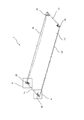
図1乃至図5、図7、図8は実施の形態1を示す図で、図1は室内ユニット100の全体構成を示す斜視図、図2は室内ユニット100の縦断面図、図3は前面開閉パネル1の裏側から見た斜視図、図4は図3のA部拡大図、図5は図3のB部拡大図、図7は保持具40とそれに装着または取り外し中の状態である前面開閉パネル1のアーム25部を示す斜視図、図8は係止具50とそれに嵌入しているツメ26の関係を示す斜視図である。室内ユニット100の係止具50とツメ26の関係を示す斜視図である。また、図6は比較のために示す従来の前面開閉パネル1の裏側から見た斜視図である。
1 to 5, 7, and 8 show the first embodiment. FIG. 1 is a perspective view showing the overall configuration of the
図1、図2を参照しながら、空気調和機の室内ユニット100の全体構成を説明する。但し、本実施の形態は、前面開閉パネル1に特徴がある。その他の部分は、公知の空気調和機の室内ユニット100と同様であるので、簡単に説明する。
The overall configuration of the
図1、図2に示す室内ユニット100は、室内の壁等に取付けられる壁掛け式のものである。空気調和機は、室内ユニット100と、室外ユニット(図示せず)と、使用者が室内で操作するリモコン(図示せず)とを備える。室外ユニット及び使用者が室内で操作するリモコンは、本実施の形態には関係しないので説明は省略する。
The
室内ユニット100の本体(筐体)は、本体背面枠3と本体前面枠2とで構成される。
The main body (housing) of the
本体背面枠3は、室内ユニット100の本体の背面側に位置する。本体背面枠3には、室内の空気を冷凍サイクル(室内ユニット100の室内熱交換器4、室外機の圧縮機、室外熱交換器、減圧装置、四方弁等で構成される冷媒回路)の冷媒と熱交換する室内熱交換器4と、室内の空気を室内ユニット100内部に吸込み、室内熱交換器4で熱交換された調和空気として室内に吹き出す室内送風機5(例えば、ラインフローファン(登録商標))とが固定される。
The main
室内熱交換器4、室内送風機5は本体背面枠3に固定されるが、本体背面枠3から室内側に突出する。この突出した部分は、本体前面枠2に収納される。本体前面枠2は、天面に室内空気を室内ユニット100の内部に吸い込む吸込口6を備える。
The indoor heat exchanger 4 and the indoor blower 5 are fixed to the main
室内熱交換器4は多段(図2では3段)に折り曲げられ、室内送風機5の前面、上面及び背面の一部を囲うように配置される。室内熱交換器4の全体形状は側面視略逆V字状である。 The indoor heat exchanger 4 is bent in multiple stages (three stages in FIG. 2), and is disposed so as to surround a part of the front surface, the upper surface, and the rear surface of the indoor blower 5. The overall shape of the indoor heat exchanger 4 is a substantially inverted V shape when viewed from the side.
本体前面枠2の前面に、前面開閉パネル1が上部(前面開閉パネル1のアーム25が本体前面枠2の保持具装着部2aに装着される保持具(後述)に保持される)を支点にして上下方向に開閉可能に取り付けられる。前面開閉パネル1は、閉状態でツメ26が本体前面枠2(本体前面枠2の係止具装着部2bに装着される係止具(後述)に係止される)に係合して本体前面枠2の前面側を閉塞する。そして、本体前面枠2の前面側を閉塞した状態では、意匠面である前面が室内ユニット100の意匠に寄与する。
The front opening /
本体前面枠2の下部に、室内熱交換器4で冷媒と熱交換後の調和空気が吹き出される吹出口7が形成されている。吹出口7は、室内ユニット100の長手方向に延びて形成される。
A
吹出口7には、吹出口7の長手方向に沿って上下に2段に、上下風向板(上)60a、上下風向板(下)60bが設置される。上下風向板(上)60a、上下風向板(下)60bは、室内に吹き出される調和空気の上下方向の風向を調整する。上下風向板(上)60a、上下風向板(下)60bは、左右端部をそれぞれ回動自在に支持され、本体前面枠2内に収納される電動機(図示せず)により上下方向に回動して、吹出口7から室内に吹き出される調和空気の上下方向の風向を調整する。
The
空気調和機の運転停止時には、上下風向板(上)60a、上下風向板(下)60bが吹出口7を閉塞し、運転停止時の室内ユニット100の意匠性を向上させる。
When the operation of the air conditioner is stopped, the upper and lower wind direction plates (upper) 60a and the upper and lower wind direction plates (lower) 60b block the
吹出口7の口元に設けられる風の上下方向の風向を変える上下風向板(上)60a、上下風向板(下)60bは、例えば、風路70を清掃するために、取り外し可能になっている。
The vertical wind direction plate (upper) 60a and the vertical wind direction plate (lower) 60b that change the wind direction in the vertical direction of the wind provided at the mouth of the
吹出口7において、上下風向板(上)60a、上下風向板(下)60bの上流側で、室内送風機5に近い位置に、一対の左右風向板組立(図示しない)が設けられる。一対の左右風向板組立は、吹出口7の中央部付近を境にして左右に分かれて配置されている。そして、一対の左右風向板組立は、上下風向板(上)60a、上下風向板(下)60bを取り外した後、観音扉のように、それぞれ吹出口7の中央部付近から前方へ開く構成になっている。一対の左右風向板組立が前方へ開放されることにより、風路70の清掃等が可能となる。
At the
各左右風向板組立は、左右風向板ベースと、この左右風向板ベースに回動自在に取付られる左右風向板と、左右風向板ベースに着脱自在に取り付けられるファンガードとを備える。ファンガードは、左右風向板の下流側(前面側)に位置する。ファンガードは、室内送風機5への触手を抑制するために設けられる。 Each left / right wind direction plate assembly includes a left / right wind direction plate base, a left / right wind direction plate rotatably attached to the left / right wind direction plate base, and a fan guard detachably attached to the left / right wind direction plate base. The fan guard is located on the downstream side (front side) of the left and right wind direction plates. The fan guard is provided to suppress tentacles to the indoor blower 5.
室内送風機5から吹出口7に到る風路70は、背面側が本体背面枠3によって形成される。また、風路70の前面側は、本体前面枠2に固定されるノズル9によって形成される。
The
ノズル9の風路70と反対側となる上面側は、室内熱交換器4の下方に位置する。そしてノズル9の上面側は、室内熱交換器4表面のドレン水を回収するドレンパンとなる。ドレンパンに回収されたドレン水は、図示しないドレンホースを流れて室外に排出される。
The upper surface side of the nozzle 9 opposite to the
室内ユニット100の内部には、吸込口6と室内熱交換器4との間に、吸込口6から吸い込まれる室内空気に混入する塵埃等を捕集するエアフィルター71が室内熱交換器4を覆うように配置される。エアフィルター71は本体前面枠2に着脱可能に取り付けられる。そして捕集した塵埃による目詰まりを防止するために使用者が取り外して清掃や洗浄を行い、その後再び装着できるようになっている。そのエアフィルター71の着脱の際に使用者は前面開閉パネル1を開閉する。
Inside the
室内ユニット100には、エアフィルター71以外にも塵埃より粒子の小さい花粉、ダニ、カビの胞子、たばこのヤニ等室内空気中の微粒子などを捕集する空気清浄フィルター及び吸い込まれた室内空気中の臭い成分を吸着して室内空気の脱臭を行う脱臭フィルターが室内熱交換器4の上流側に配置されることもある。これら空気清浄フィルター及び脱臭フィルターの清掃、洗浄もしくは新品への交換の際にも前面開閉パネル1が使用者によって開閉される。
In addition to the
次に、室内ユニット100の基本的な動作について説明する。使用者によってリモコン等により空気調和機の運転開始が指令されると、室内ユニット100では室内送風機5が運転を開始する。室内送風機5には図示されない電動機が連結されている。この電動機が回転することによって室内送風機5が回転する。室内送風機5の回転により室内空気が吸込口6から吸い込まれ、エアフィルター71を通過する。この時吸い込まれた室内空気に含まれる塵埃をエアフィルター71が捕集する。エアフィルター71を通過した室内空気は室内送風機5の連続的な回転により更に室内熱交換器4を通過する。
Next, the basic operation of the
室内熱交換器4を通過する際に、吸い込まれた室内空気は室内熱交換器4を流れる冷凍サイクルの冷媒と熱交換される。室内熱交換器4は空気調和機の運転が冷房の時は蒸発器となって、ここで冷凍サイクルの冷媒が蒸発するため、通過する室内空気を冷やす。暖房運転であれば凝縮器となって通過する室内空気を暖める。このように、吸い込まれた室内空気は室内熱交換器4を通過する際に室内熱交換器4を流れる冷媒と熱交換して、使用者が所望する調和空気となる。エアフィルター71が吸い込まれた室内空気の塵埃を捕集することにより室内熱交換器4への塵埃の付着を防止し、室内熱交換器4の塵埃付着による熱交換性能の低下を防いでいる。
When passing through the indoor heat exchanger 4, the sucked indoor air is heat-exchanged with the refrigerant of the refrigeration cycle flowing through the indoor heat exchanger 4. The indoor heat exchanger 4 becomes an evaporator when the operation of the air conditioner is cooling, and the refrigerant in the refrigeration cycle evaporates here, so that the passing indoor air is cooled. If it is a heating operation, it becomes a condenser and warms the passing indoor air. Thus, the sucked indoor air exchanges heat with the refrigerant flowing through the indoor heat exchanger 4 when passing through the indoor heat exchanger 4, and becomes conditioned air desired by the user. The
室内熱交換器4で冷媒と熱交換された室内空気は調和空気となって、室内送風機5の連続的な回転により風路70を通って吹出口7から室内に吹き出される。吹出口7から吹き出される際に、上下風向板(上)60a、上下風向板(下)60b及び図示しない左右風向板が回動して、吹き出される調和空気の風向が調整される。上下風向板(上)60a、上下風向板(下)60b及び図示しない左右風向板は、それぞれ室内ユニット100に内蔵される電動機によって回動される。
The indoor air heat-exchanged with the refrigerant in the indoor heat exchanger 4 becomes conditioned air, and is blown into the room from the
また、室内送風機5の回転数を変化させることで吹き出される風量も調整される。使用者により空気調和機の運転停止が指令されると、上下風向板(上)60a、上下風向板(下)60bは、吹出口7を閉塞する状態まで回動し、吹出口7を閉塞して静止する。
Moreover, the air volume blown off by changing the rotation speed of the indoor fan 5 is also adjusted. When the user instructs to stop the operation of the air conditioner, the upper and lower airflow direction plates (upper) 60a and the upper and lower airflow direction plate (lower) 60b rotate until the
次に本実施の形態の特徴部分である前面開閉パネル1について説明する。図3は前面開閉パネル1の裏側から見た斜視図である。前面開閉パネル1の左右端部に、前面開閉パネル1を室内ユニット100の本体前面枠2の上部に開閉可能に結合するアーム25と、前面開閉パネル1が閉時に前面開閉パネル1を室内ユニット100の本体前面枠2に対して閉状態を保持するツメ26が立設している。
Next, the front opening /
前面開閉パネル1は、全体が略長方形の板状である。その長手方向(左右方向)は、室内ユニット100の左右方向に一致する。略長方形の板状部分をパネル部1aと呼ぶ。
The front opening /
パネル部1aの外周部には、裏面側(前面開閉パネル1が閉じたときに本体前面側となる面で、意匠面と反対側の面である)に立設する外周壁(フランジ部)が設けられる。前面開閉パネル1を室内ユニット100に取付けたときに上になる外周壁を上側外周壁1bとする。前面開閉パネル1を室内ユニット100に取付けたときに側面に位置する外周壁を側面外周壁1cとする。側面外周壁1cは、左右に2箇所ある。前面開閉パネル1を室内ユニット100に取付けたときに下になる外周壁を下側外周壁1dとする。
An outer peripheral wall (flange portion) standing on the rear surface side (the surface that becomes the front surface of the main body when the front opening /
先ず、前面開閉パネル1を室内ユニット100の本体前面枠2の上部に開閉可能に結合するアーム25の構成を、図4の拡大図により説明する。
First, the structure of the
前面開閉パネル1のパネル部1aの裏面に、アーム25を設置する台座25aが設けられる。台座25aは、パネル部1aの裏面から離間(所定の距離だけ離れて)して設けられる。台座25aは、パネル部1a等と連結する脚部を有する。
A
脚部25a−1は、上側外周壁1bに略平行に、側面外周壁1cに略垂直にパネル部1aに設けられる。
The
脚部25a−2は、上側外周壁1bの方向に設けられる。脚部25a−2は、パネル部1aと上側外周壁1bとが交わる角部と台座25aを連結するように傾斜して設けられる。
The
脚部25a−3は、側面外周壁1cの方向に設けられる。脚部25a−3は、パネル部1aと側面外周壁1cとが交わる角部と台座25aを連結するように傾斜(屈曲)して設けられる。
The
脚部25a−1、脚部25a−2、脚部25a−3は、厚さの薄い薄肉のリブのような形状である。
The
アーム25の先端(上部)に、本体前面枠2の保持具装着部2aの保持具(後述)に回動自在に保持される回動軸25bが設けられる。回動軸25bは、前面開閉パネル1の長手方向に平行に、且つ両端の回動軸25bが向き合うように形成されている。
At the tip (upper part) of the
また、アーム25のL字に屈曲する部分の近傍に、前面開閉パネル1を所定の角度で開状態を保持するための保持面25cが形成されている。
Also, a holding
アーム25は、前面開閉パネル1のパネル部1aの裏面から離間(所定の距離だけ離れて)して設けられる台座25aに立設する。そして、台座25aは、薄肉の脚部25a−1、脚部25a−2、脚部25a−3で、パネル部1a又はパネル部1aと上側外周壁1bもしくは側面外周壁1cとが交わる角部と連結している。そのため、前面開閉パネル1の樹脂射出成形時に、パネル部1a等の裏側に厚いリブや太いボスがないので、パネル部1aの意匠面に「ひけ」(樹脂成形品表面の凹み)が発生しにくい。また、脚部25a−2、脚部25a−3は、パネル部1aと上側外周壁1bもしくは側面外周壁1cとが交わる角部と連結しているので、仮に「ひけ」が発生しても目立たない。
The
次に、前面開閉パネル1が閉時に前面開閉パネル1を室内ユニット100の本体前面枠2に対して閉状態を保持するツメ26の構成を、図5の拡大図により説明する。
Next, the structure of the
前面開閉パネル1のパネル部1aの裏面に、ツメ26を設置する台座26aが設けられる。台座26aは、パネル部1aの裏面から離間(所定の距離だけ離れて)して設けられる。台座26aは、パネル部1aと連結する脚部を有する。台座26aには、ツメ26の他に、前面開閉パネル1を閉じる際にツメ26を本体前面枠2の係止具装着部2b内に収納固定されている係止具に係止するが、その挿入の案内となる挿入用案内27が設けられている。挿入用案内27は、本体前面枠2の凹部(図示せず)に収納される。
A
脚部26a−1は、下側外周壁1dに略平行に、側面外周壁1cに略垂直にパネル部1aに設けられる。脚部26a−1は、傾斜している。
The
脚部26a−2は、脚部26a−1と対向する。脚部26a−2は、パネル部1aと下側外周壁1dとが交わる角部と台座26aを連結するように傾斜して設けられる。
脚部26a−1、脚部26a−2は、厚さの薄い薄肉のリブのような形状である。
The
ツメ26の形状は、側面視(例えば、側面外周壁1c側から見て)ひし形である。
The shape of the
ツメ26は、前面開閉パネル1のパネル部1aの裏面から離間(所定の距離だけ離れて)して設けられる台座26aに立設する。そして、台座26aは、薄肉の脚部26a−1、脚部26a−2で、パネル部1a又はパネル部1aと下側外周壁1dとが交わる角部と連結している。そのため、前面開閉パネル1の樹脂射出成形時に、パネル部1a等の裏側に厚いリブや太いボスがないので、パネル部1aの意匠面に「ひけ」(樹脂成形品表面の凹み)が発生しにくい。また、脚部26a−2は、パネル部1aと下側外周壁1dとが交わる角部と連結しているので、仮に「ひけ」が発生しても目立たない。
The
図6は比較のために示す従来の前面開閉パネル101の裏側から見た斜視図である。図3に示す前面開閉パネル1と、台座部分を除く他の構成は略同じである。従来の前面開閉パネル101は、アーム125が台座を備えていない。アーム125は、前面開閉パネル101のパネル部101aから直接立設している。ツメ126部分についても同様である。
FIG. 6 is a perspective view seen from the back side of a conventional front opening /
そのため、前面開閉パネル101の樹脂射出成形時に、パネル部101a等の裏側に厚いリブや太いボスが存在することになるので、パネル部101aの意匠面に「ひけ」(樹脂成形品表面の凹み)が発生する。
Therefore, when resin injection molding of the front opening /
次に、前面開閉パネル1を室内ユニット100の本体前面枠2に回動自在に、且つ着脱可能に取り付ける方法について説明する。図1に示すように、本体前面枠2の上部両側に、本体前面枠2の正面から奥側(本体背面枠3側)に凹んでその底面に傾斜した溝を有した保持具装着部2aがそれぞれ一体成形されている。その溝の傾斜方向は、手前側すなわち正面側が下方、奥側が上方に位置するような傾斜である。その溝に図7に示す保持具40がそれぞれの保持具装着部2aの底面溝に嵌められている。図7は保持具40とそれに装着または取り外し中の状態である前面開閉パネル1のアーム25部を示す斜視図である。
Next, a method of attaching the front opening /
保持具40は、本体前面枠2とは別体に、自己潤滑性のある樹脂で一体成形される。本体前面枠2の保持具装着部2a底面に形成される溝の上下両端面に、保持具40の上係止片41、下係止片42がそれぞれ嵌って本体前面枠2に固定される。図7において下側に位置する下係止片42が保持具装着部2aの溝の下端面に保持される。
The
保持具40の略中央には上方に開口するU字状の開度保持部43が形成される。上部にはアーム25の回動軸25bを回動自在に支持し、下方側のみ略半円状に形成された軸受44が形成されている。開度保持部43は上部の開口が少し狭められていて、その開口幅はアーム25の保持面25cが位置する部分の幅よりも小さい。ただし開口を除いたU字状の開度保持部43内面間の幅はアーム25の保持面25cが位置する部分の幅よりも大きく形成されている。
A U-shaped
図1に示すように、本体前面枠2の下部両側に、本体前面枠2の正面から奥側(本体背面枠3側)に凹んだ係止具装着部2bがそれぞれ一体成形されている。その係止具装着部2b内に図8に示す係止具50が収納固定されている。図8は係止具50とそれに嵌入して前面開閉パネル1の閉状態を保持しているツメ26を示す斜視図である。左右2ヶ所の係止具装着部2bの位置は、本体前面枠2の長手方向中央に対して対称である必要はなく、本体前面枠2が収納する他の部品との関係から適宜設定されればよいが、本体前面開閉パネル1の下部寄りに位置させる。
As shown in FIG. 1, locking
係止具50は、本体前面枠2とは別体に、自己潤滑性のある樹脂で一体成形される。その略中央に開口が傾斜して狭められている略U字状のツメ収納部51が形成されていて、その開口が本体前面枠2の前面側となり、U字状が略鉛直状態(室内ユニット100の長手方向と略垂直)となるように係止具装着部2bに配置されている。
The
前面開閉パネル1を室内ユニット100の本体前面枠2に装着するには、先ず前面開閉パネル1の両側下方を持って、前面開閉パネル1を本体前面枠2に対して略90°の状態としてから両側のアーム25の先端を左右略同時に本体前面枠2の係止具装着部2b内に挿入し、アーム25の先端に形成されている回動軸25bを保持具40に形成されている軸受44に嵌合させる。
In order to attach the front opening /
軸受44は下方側だけの半円状であるので、嵌合させるというのは、軸受44の内周面に載せることである。なお軸受44が下方側しか存在しないのは、前面開閉パネル1の自重という一定方向の荷重しか支持しなくてよいためである。
Since the
軸受44への回動軸25bの嵌合は、前面開閉パネル1を本体前面枠2に対して略90°の状態で奥側すなわち本体背面枠3側に押し付けることで、突設している軸受44の前面側に位置する先端部44aが回動軸25bによって弾性変形して押し下げられることで、回動軸25bが軸受44の先端部44aを乗り越えて軸受44の内周面上に載置される。
The
軸受44は回動軸25bが先端部44aを乗り越えると弾性変形が解除される。このように軸受44が弾性変形して回動軸25bが軸受44に嵌合され、嵌合後は軸受44の弾性変形が解除されるので、前面開閉パネル1の取り付け作業者は、軸受44の弾性変形を手応えとして感じることができるので、装着の完了、そして正常に装着できたかをこの手応えから判断することが可能となる。
The elastic deformation of the
回動軸25bの軸受44への嵌合が両側とも完了すると、前面開閉パネル1を閉状態とすべく回動軸25bを回動支点として下方に下げる。そのときの開口の両側に位置する上端面43aにアーム25の保持面25cが接触して停止する。この状態が前面開閉パネル1を開状態に保持しているときである。
When the fitting of the
前面開閉パネル1を更に下方へ回動させようと力を加えると、アーム25の両側の保持面25cがU字状の開度保持部43を外側に弾性変形させ、開度保持部43の開口を乗り越え、U字状の開度保持部43の内面間へと進入する。開度保持部43の内面間の幅はアーム25の保持面25cが位置する部分の幅よりも大きく形成されているので、アーム25が開度保持部43の開口を通過して開度保持部43の内面間に収納されると開度保持部43の弾性変形は終了する。
When a force is applied to further rotate the front opening /
前面開閉パネル1の下方への回動を続けると、ツメ26が本体前面枠2に固定された係止具50と接触する。そして菱状のツメ26が係止具50のツメ収納部51の傾斜して狭めらている開口を広げて、すなわちツメ収納部51を外側に弾性変形させてツメ収納部51内に進入して収納される。ツメ26のツメ収納部51内への収納が完了すると、ツメ収納部51の弾性変形が解除される。取り付け作業者はこのツメ収納部51の弾性変形の解除を手応えとして感じることができ、ツメ26の収納完了をこの手応えにより判断できる。
When the front opening /
ツメ収納部51は開口の幅がツメ26の左右方向の幅よりも狭いので、ツメ26のツメ収納部51開口からの自発的な脱出を防ぎ、前面開閉パネル1の下方部分の浮き上がりを防止している。ツメ26がツメ収納部51に収納され、ツメ26がツメ収納部51の開口に引っ掛かることで、前面開閉パネル1が浮き上がることなく、閉状態が安定的に保持され、外観の見映えがよくなり、前面開閉パネル1が回動軸25bを支点にして回動方向にがたつくこともない。
Since the width of the opening of the
続いて使用者による前面開閉パネル1の開閉作業について説明する。使用者は前述したようなエアフィルター71の清掃等のために、あるいは室内ユニット100の清掃のために室内の壁に設置された室内ユニット100の前面開閉パネル1を開閉する。前面開閉パネル1を使用者が開けるには、まず室内ユニット100が停止状態の時に、前面開閉パネル1の両側の手掛け部1e(図5参照)に指をかけ、手前(使用者自身の方)に引くようにして、左右のツメ26を係止具50のツメ収納部51から抜き出す。
Next, the opening / closing operation of the front opening /
以上のように、本実施の形態によれば、本体前面枠2の前面に上下方向に開閉可能に取り付けられる前面開閉パネル1の意匠面と反対側の裏面に設けられるアーム25(本体前面枠2の保持具装着部2aに装着される保持具40に保持される)と、ツメ26(本体前面枠2の係止具装着部2bに装着される係止具50に係止される)とが、パネル部1aの裏面から離間(所定の距離だけ離れて)して設けられる台座25a又は台座26aに立設されている。そして、台座25a又は台座26aは、薄肉の脚部でパネル部1a又は前面開閉パネル1の外周壁と連結する構成にした。従って、前面開閉パネル1の樹脂射出成形時に、パネル部1a等の裏側に厚いリブや太いボスがないので、パネル部1aの意匠面に「ひけ」(樹脂成形品表面の凹み)が発生しにくい。また、脚部は、パネル部1aと外周壁とが交わる角部と連結しているので、仮に「ひけ」が発生しても目立たない。
As described above, according to the present embodiment, the arm 25 (main
1 前面開閉パネル、1a パネル部、1b 上側外周壁、1c 側面外周壁、1d 下側外周壁、1e 手掛け部、2 本体前面枠、2a 保持具装着部、2b 係止具装着部、3 本体背面枠、4 室内熱交換器、5 室内送風機、6 吸込口、7 吹出口、9 ノズル、25 アーム、25a 台座、25a−1 脚部、25a−2 脚部、25a−3 脚部、25b 回動軸、25c 保持面、26 ツメ、26a 台座、26a−1 脚部、26a−2 脚部、27 挿入用案内、40 保持具、41 上係止片、42 下係止片、43 開度保持部、43a 上端面、44 軸受、44a 先端部、50 係止具、51 ツメ収納部、60a 上下風向板(上)、60b 上下風向板(下)、70 風路、71 エアフィルター、100 室内ユニット、101 前面開閉パネル、101a パネル部、125 アーム、126 ツメ。
DESCRIPTION OF
Claims (3)
本体前面枠と本体背面枠とからなる本体と、
前記本体前面枠に開閉自在に取り付けられる前面開閉パネルと、
前記前面開閉パネルの裏面に設けられ、前記本体前面枠に回動自在に保持されるアームと、
前記前面開閉パネルの裏面に設けられ、該前面開閉パネルの閉状態で、本体前面枠に係止されるツメと、
前記アーム又は前記ツメが立設され、前記前面開閉パネルの裏面に該前面開閉パネルから離間して設けられる台座と、
前記前面開閉パネルと前記台座とを連結する薄肉の脚部とを備え、
前記前面開閉パネルは、表側が意匠面となるパネル部と、前記パネル部の外周部の裏側に立設する外周壁を備え、
前記脚部は前記パネル部の裏面に対して傾斜して設けられ、
前記脚部の一部は前記パネル部と前記外周壁とが交差する角部に連結されていることを特徴とする空気調和機の室内ユニット。 In an indoor unit of a wall-mounted air conditioner,
A main body composed of a front frame and a rear frame;
A front opening / closing panel attached to the main body front frame so as to be freely opened and closed;
An arm provided on the back surface of the front opening / closing panel and rotatably held on the main body front frame;
A claw that is provided on the back surface of the front opening / closing panel and is locked to the front frame of the main body in a closed state of the front opening / closing panel;
The arm or the claw is erected, and a pedestal provided on the back surface of the front opening / closing panel and spaced from the front opening / closing panel;
A thin leg for connecting the front opening / closing panel and the pedestal ;
The front open / close panel includes a panel portion whose front side is a design surface, and an outer peripheral wall standing on the back side of the outer peripheral portion of the panel portion,
The leg portion is provided to be inclined with respect to the back surface of the panel portion,
An indoor unit of an air conditioner, wherein a part of the leg part is connected to a corner part where the panel part and the outer peripheral wall intersect .
前記台座は、パネル部の左右端部の上部又は下部に設けられ、The pedestal is provided at the upper or lower part of the left and right ends of the panel part,
前記外周壁は、略長方形のパネル部の外周四辺に対応して、上側外周壁と下側外周壁と左外周壁と右外周壁とを有し、The outer peripheral wall has an upper outer peripheral wall, a lower outer peripheral wall, a left outer peripheral wall, and a right outer peripheral wall, corresponding to the outer peripheral four sides of the substantially rectangular panel portion,
前記脚部は、上側外周壁と下側外周壁とのいずれかと前記パネル部とが交差する角部に連結されている第1の脚部と、左外周壁と右外周壁とのいずれかと前記パネル部とが交差する角部に連結されている第2の脚部とを有することを特徴とする請求項1又は2記載の空気調和機の室内ユニット。The leg portion includes a first leg portion connected to a corner portion where either the upper outer peripheral wall or the lower outer peripheral wall and the panel portion intersect, one of the left outer peripheral wall and the right outer peripheral wall, and The indoor unit of an air conditioner according to claim 1 or 2, further comprising a second leg portion connected to a corner portion intersecting with the panel portion.
Priority Applications (5)
| Application Number | Priority Date | Filing Date | Title |
|---|---|---|---|
| JP2007332792A JP4490475B2 (en) | 2007-12-25 | 2007-12-25 | Air conditioner indoor unit |
| AU2008203280A AU2008203280B2 (en) | 2007-12-25 | 2008-07-23 | Indoor unit of air conditioner |
| US12/178,166 US8171748B2 (en) | 2007-12-25 | 2008-07-23 | Indoor unit of air conditioner |
| ES08253799.4T ES2675752T3 (en) | 2007-12-25 | 2008-11-24 | Indoor unit of air conditioner |
| EP08253799.4A EP2075510B1 (en) | 2007-12-25 | 2008-11-24 | Indoor unit of air conditioner |
Applications Claiming Priority (1)
| Application Number | Priority Date | Filing Date | Title |
|---|---|---|---|
| JP2007332792A JP4490475B2 (en) | 2007-12-25 | 2007-12-25 | Air conditioner indoor unit |
Publications (2)
| Publication Number | Publication Date |
|---|---|
| JP2009156490A JP2009156490A (en) | 2009-07-16 |
| JP4490475B2 true JP4490475B2 (en) | 2010-06-23 |
Family
ID=40351788
Family Applications (1)
| Application Number | Title | Priority Date | Filing Date |
|---|---|---|---|
| JP2007332792A Expired - Fee Related JP4490475B2 (en) | 2007-12-25 | 2007-12-25 | Air conditioner indoor unit |
Country Status (5)
| Country | Link |
|---|---|
| US (1) | US8171748B2 (en) |
| EP (1) | EP2075510B1 (en) |
| JP (1) | JP4490475B2 (en) |
| AU (1) | AU2008203280B2 (en) |
| ES (1) | ES2675752T3 (en) |
Families Citing this family (20)
| Publication number | Priority date | Publication date | Assignee | Title |
|---|---|---|---|---|
| KR101542389B1 (en) * | 2009-02-05 | 2015-08-06 | 엘지전자 주식회사 | A Heat Pump Module and A Drying Machine having the heat pump module |
| US8490438B2 (en) * | 2009-02-05 | 2013-07-23 | Lg Electronics Inc. | Laundry treatment device |
| EP2398947B1 (en) * | 2009-02-23 | 2016-10-26 | LG Electronics Inc. | Washing / drying machine |
| EP2398948B1 (en) * | 2009-02-23 | 2018-09-12 | LG Electronics Inc. | Washing machine |
| KR101603106B1 (en) | 2009-03-03 | 2016-03-14 | 엘지전자 주식회사 | Washing machine |
| US8627672B2 (en) | 2009-08-27 | 2014-01-14 | Sanyo Electric Co., Ltd. | Wall-hung air conditioner and installing device for air conditioner |
| KR101781845B1 (en) * | 2010-05-13 | 2017-09-26 | 엘지전자 주식회사 | Indoor unit of air conditioner |
| CN102313346B (en) * | 2010-06-29 | 2015-04-08 | 珠海格力电器股份有限公司 | Air-condition indoor machine |
| KR101852800B1 (en) * | 2011-10-20 | 2018-04-27 | 엘지전자 주식회사 | Indoor unit of air conditioner |
| JP5805057B2 (en) * | 2012-12-11 | 2015-11-04 | 三菱電機株式会社 | Air conditioner indoor unit design panel and air conditioner indoor unit |
| JP6272121B2 (en) * | 2014-04-21 | 2018-01-31 | 三菱電機株式会社 | Air conditioner |
| KR101742502B1 (en) * | 2015-12-31 | 2017-06-01 | 엘지전자 주식회사 | An air conditioner |
| CN206847028U (en) * | 2016-01-18 | 2018-01-05 | 三菱电机株式会社 | The indoor set of air conditioner |
| EP3367008B1 (en) * | 2016-07-25 | 2019-12-25 | Mitsubishi Electric Corporation | Outdoor unit for air conditioner |
| US11149966B2 (en) * | 2017-03-09 | 2021-10-19 | Mitsubishi Electric Corporation | Indoor unit of air-conditioning apparatus |
| CN107420987A (en) * | 2017-07-05 | 2017-12-01 | 广东美的制冷设备有限公司 | Indoor apparatus of air conditioner |
| EP3657081A4 (en) * | 2017-09-12 | 2020-08-05 | GD Midea Air-Conditioning Equipment Co., Ltd. | Air conditioner |
| CN107576049B (en) * | 2017-10-25 | 2023-02-28 | 奥克斯空调股份有限公司 | Tectorial membrane panel and air conditioner complete machine |
| CN109812871B (en) * | 2019-03-13 | 2024-05-03 | 珠海格力电器股份有限公司 | Air conditioner |
| WO2021219111A1 (en) | 2020-04-30 | 2021-11-04 | 海信(广东)空调有限公司 | Detachable and washable air conditioner indoor unit |
Citations (5)
| Publication number | Priority date | Publication date | Assignee | Title |
|---|---|---|---|---|
| JPS59190519U (en) * | 1983-06-06 | 1984-12-18 | 河西工業株式会社 | Sink prevention structure for injection molded products |
| JPH07112454A (en) * | 1993-10-19 | 1995-05-02 | Sekisui Chem Co Ltd | Boss structure of plastic molded article |
| JP2000234759A (en) * | 1999-02-10 | 2000-08-29 | Mitsubishi Electric Corp | Panel-opening/closing device of air-conditioner |
| JP2007225253A (en) * | 2006-02-27 | 2007-09-06 | Fujitsu General Ltd | Air conditioner |
| JP2007245413A (en) * | 2006-03-14 | 2007-09-27 | Toyoda Gosei Co Ltd | Design cover |
Family Cites Families (10)
| Publication number | Priority date | Publication date | Assignee | Title |
|---|---|---|---|---|
| US4292815A (en) * | 1979-07-25 | 1981-10-06 | Carrier Corporation | Door assembly for a self-contained air conditioning unit |
| JPS5867217U (en) | 1981-10-28 | 1983-05-07 | 株式会社 くろがね工作所 | Fan coil unit front plate mounting device |
| JPH05133541A (en) | 1991-11-14 | 1993-05-28 | Sanyo Electric Co Ltd | Air-conditioner |
| JP3271320B2 (en) | 1992-09-07 | 2002-04-02 | ダイキン工業株式会社 | Panel mounting device and heat exchange ventilation device including the same |
| JPH06249457A (en) | 1993-02-26 | 1994-09-06 | Sanyo Electric Co Ltd | Air conditioner |
| JPH11166749A (en) | 1997-12-03 | 1999-06-22 | Mitsubishi Electric Corp | Air-condition |
| JP4187360B2 (en) | 1999-08-26 | 2008-11-26 | 東芝キヤリア株式会社 | Air conditioner indoor unit |
| JP3642064B2 (en) | 2003-09-01 | 2005-04-27 | ダイキン工業株式会社 | Indoor unit for air conditioner and method for manufacturing the same |
| DE10341329B4 (en) * | 2003-09-08 | 2005-09-22 | Fraunhofer-Gesellschaft zur Förderung der angewandten Forschung e.V. | Apparatus and method for increasing occupant protection in a vehicle in a side impact |
| JP3864951B2 (en) | 2003-11-19 | 2007-01-10 | 松下電器産業株式会社 | Air conditioner |
-
2007
- 2007-12-25 JP JP2007332792A patent/JP4490475B2/en not_active Expired - Fee Related
-
2008
- 2008-07-23 AU AU2008203280A patent/AU2008203280B2/en not_active Ceased
- 2008-07-23 US US12/178,166 patent/US8171748B2/en not_active Expired - Fee Related
- 2008-11-24 EP EP08253799.4A patent/EP2075510B1/en not_active Expired - Fee Related
- 2008-11-24 ES ES08253799.4T patent/ES2675752T3/en active Active
Patent Citations (5)
| Publication number | Priority date | Publication date | Assignee | Title |
|---|---|---|---|---|
| JPS59190519U (en) * | 1983-06-06 | 1984-12-18 | 河西工業株式会社 | Sink prevention structure for injection molded products |
| JPH07112454A (en) * | 1993-10-19 | 1995-05-02 | Sekisui Chem Co Ltd | Boss structure of plastic molded article |
| JP2000234759A (en) * | 1999-02-10 | 2000-08-29 | Mitsubishi Electric Corp | Panel-opening/closing device of air-conditioner |
| JP2007225253A (en) * | 2006-02-27 | 2007-09-06 | Fujitsu General Ltd | Air conditioner |
| JP2007245413A (en) * | 2006-03-14 | 2007-09-27 | Toyoda Gosei Co Ltd | Design cover |
Also Published As
| Publication number | Publication date |
|---|---|
| EP2075510B1 (en) | 2018-05-30 |
| AU2008203280A1 (en) | 2009-07-09 |
| AU2008203280B2 (en) | 2011-03-24 |
| EP2075510A3 (en) | 2010-03-31 |
| US20090158765A1 (en) | 2009-06-25 |
| EP2075510A2 (en) | 2009-07-01 |
| US8171748B2 (en) | 2012-05-08 |
| ES2675752T3 (en) | 2018-07-12 |
| JP2009156490A (en) | 2009-07-16 |
Similar Documents
| Publication | Publication Date | Title |
|---|---|---|
| JP4490475B2 (en) | Air conditioner indoor unit | |
| US7594411B2 (en) | Indoor unit for air conditioner | |
| KR102217013B1 (en) | Indoor unit of ceiling type air-conditioner | |
| JP3587151B2 (en) | Air conditioner with humidification function | |
| KR100509018B1 (en) | Dust collector unit mounting structure for indoor unit of air conditioner | |
| JP2004219049A (en) | Air conditioner | |
| KR20080041061A (en) | Air conditioner | |
| KR20060020591A (en) | Air-cleaner in stand type air-conditioner | |
| KR100584295B1 (en) | A front frame mounting structure of an air conditioner | |
| JP3327504B2 (en) | Air conditioner | |
| JPH1123051A (en) | Air filter for air conditioner | |
| KR101178974B1 (en) | Indoor unit for air conditioner | |
| KR101140706B1 (en) | Indoor unit of air conditioner | |
| KR20090061941A (en) | Apparatus for guiding suction air in air conditioner | |
| KR100626429B1 (en) | Air conditioner | |
| KR20070075509A (en) | Indoor unit for air conditioner | |
| KR200312147Y1 (en) | Structure of room air-conditioner | |
| JP4739512B2 (en) | Air conditioner | |
| KR200186562Y1 (en) | Airconditioner | |
| KR101220756B1 (en) | Indoor unit of air conditioner | |
| JPH08168622A (en) | Air purifier | |
| KR101101424B1 (en) | Air conditioner's indoor apparatus | |
| JP2015021639A (en) | Air conditioner | |
| KR200235022Y1 (en) | Ventilation control device for window air conditioner | |
| JPH0436526A (en) | Window type air conditioner |
Legal Events
| Date | Code | Title | Description |
|---|---|---|---|
| A621 | Written request for application examination |
Free format text: JAPANESE INTERMEDIATE CODE: A621 Effective date: 20090520 |
|
| A977 | Report on retrieval |
Free format text: JAPANESE INTERMEDIATE CODE: A971007 Effective date: 20091106 |
|
| A131 | Notification of reasons for refusal |
Free format text: JAPANESE INTERMEDIATE CODE: A131 Effective date: 20091117 |
|
| A521 | Request for written amendment filed |
Free format text: JAPANESE INTERMEDIATE CODE: A523 Effective date: 20091225 |
|
| TRDD | Decision of grant or rejection written | ||
| A01 | Written decision to grant a patent or to grant a registration (utility model) |
Free format text: JAPANESE INTERMEDIATE CODE: A01 Effective date: 20100323 |
|
| A01 | Written decision to grant a patent or to grant a registration (utility model) |
Free format text: JAPANESE INTERMEDIATE CODE: A01 |
|
| A61 | First payment of annual fees (during grant procedure) |
Free format text: JAPANESE INTERMEDIATE CODE: A61 Effective date: 20100401 |
|
| FPAY | Renewal fee payment (event date is renewal date of database) |
Free format text: PAYMENT UNTIL: 20130409 Year of fee payment: 3 |
|
| R150 | Certificate of patent or registration of utility model |
Free format text: JAPANESE INTERMEDIATE CODE: R150 Ref document number: 4490475 Country of ref document: JP Free format text: JAPANESE INTERMEDIATE CODE: R150 |
|
| FPAY | Renewal fee payment (event date is renewal date of database) |
Free format text: PAYMENT UNTIL: 20130409 Year of fee payment: 3 |
|
| FPAY | Renewal fee payment (event date is renewal date of database) |
Free format text: PAYMENT UNTIL: 20140409 Year of fee payment: 4 |
|
| R250 | Receipt of annual fees |
Free format text: JAPANESE INTERMEDIATE CODE: R250 |
|
| R250 | Receipt of annual fees |
Free format text: JAPANESE INTERMEDIATE CODE: R250 |
|
| R250 | Receipt of annual fees |
Free format text: JAPANESE INTERMEDIATE CODE: R250 |
|
| R250 | Receipt of annual fees |
Free format text: JAPANESE INTERMEDIATE CODE: R250 |
|
| R250 | Receipt of annual fees |
Free format text: JAPANESE INTERMEDIATE CODE: R250 |
|
| R250 | Receipt of annual fees |
Free format text: JAPANESE INTERMEDIATE CODE: R250 |
|
| R250 | Receipt of annual fees |
Free format text: JAPANESE INTERMEDIATE CODE: R250 |
|
| LAPS | Cancellation because of no payment of annual fees |