EP3649857B1 - Landwirtschaftliches spritzgerät - Google Patents
Landwirtschaftliches spritzgerät Download PDFInfo
- Publication number
- EP3649857B1 EP3649857B1 EP19401041.9A EP19401041A EP3649857B1 EP 3649857 B1 EP3649857 B1 EP 3649857B1 EP 19401041 A EP19401041 A EP 19401041A EP 3649857 B1 EP3649857 B1 EP 3649857B1
- Authority
- EP
- European Patent Office
- Prior art keywords
- application
- elements
- application elements
- agricultural
- spray
- Prior art date
- Legal status (The legal status is an assumption and is not a legal conclusion. Google has not performed a legal analysis and makes no representation as to the accuracy of the status listed.)
- Active
Links
Images

Classifications
-
- A—HUMAN NECESSITIES
- A01—AGRICULTURE; FORESTRY; ANIMAL HUSBANDRY; HUNTING; TRAPPING; FISHING
- A01M—CATCHING, TRAPPING OR SCARING OF ANIMALS; APPARATUS FOR THE DESTRUCTION OF NOXIOUS ANIMALS OR NOXIOUS PLANTS
- A01M7/00—Special adaptations or arrangements of liquid-spraying apparatus for purposes covered by this subclass
- A01M7/005—Special arrangements or adaptations of the spraying or distributing parts, e.g. adaptations or mounting of the spray booms, mounting of the nozzles, protection shields
- A01M7/006—Mounting of the nozzles
Definitions
- the invention relates to a method for applying spray liquid according to the preamble of claim 1.
- spraying liquid When spraying liquid is applied to an agricultural area, it is advantageous if the spray liquid is released into the immediate vicinity of the respective plants on the agricultural area. Since a large number of agricultural crops are sown along rows of seeds, rows of plants are formed on the agricultural area as the crops grow.
- a particularly effective and effective application of spray liquid can therefore be achieved in that the spray liquid is applied in relation to rows, so that the spray liquid is applied essentially along application strips, the application strips running along rows of plants.
- the object on which the invention is based is thus to improve the precision in the row-related application of spray liquid.
- An agricultural spraying device of the type mentioned at the outset is proposed, the agricultural spraying device having a control device which is set up to control the adjusting device as a function of the rows of plants on the agricultural area detected by the detection device during the application process.
- the invention makes use of the knowledge that by controlling the adjustment device, depending on the rows of plants detected by the detection device, the area of impact of a spreading element or the areas of impact of several spreading elements can be adapted to irregularities in the spacing of the plant rows. In this way a precise row-related application of spray liquid can take place, even if adjacent rows of plants on the agricultural area are sometimes at different distances from one another.
- the control device can be set up to control the adjustment device in such a way that the areas of impingement of the spray liquid released by one or more application elements lie in the row areas of the agricultural area which have rows of plants.
- the control device can be set up to control the adjustment device in such a way that the areas of impingement of the spray liquid released by one or more application elements lie in intermediate areas which run between adjacent rows of plants. In this way, spray liquid can be applied in a targeted manner to the row areas and / or the intermediate areas running between the row areas.
- the adjusting device has one or more positioning devices, by means of which the position of one or more application elements on the spray boom can be changed.
- Individual positioning of individual dispensing elements can preferably be implemented by means of a plurality of positioning devices.
- all of the dispensing elements can each be positioned independently of other dispensing elements by means of a positioning device.
- a group of several dispensing elements can be positioned, with a group of dispensing elements being able to be positioned at the same time as part of a group positioning.
- the positioning devices can preferably be used to change the position of one or more application elements along the sprayer boom of the agricultural sprayer, that is, transversely to the direction of travel of the agricultural sprayer.
- the entire sprayer boom together with the application elements arranged on the sprayer boom can also be moved by means of a positioning device.
- an agricultural spraying device is advantageous in which the one or more positioning devices each have a displacement mechanism by means of which the one or more application elements can be displaced along the spray boom.
- the respective sliding mechanisms can have an adjustment rail which extends over a section of the sprayer boom transversely to the direction of travel of the agricultural sprayer.
- One or more discharge elements are preferably fastened to the respective adjustment rails and can be displaced along the adjustment rails.
- the control device is set up to control the one or more positioning devices in such a way that individual or more application elements are each positioned essentially vertically above a row of plants during the application process. By positioning individual or several application elements vertically above a row of plants, row-related application of spray liquid can take place particularly precisely.
- the control device can be set up to position the one or more positioning devices in this way control that individual or several application elements are positioned above and essentially in the middle between two rows of plants during the application process. By positioning individual or multiple application elements above and essentially in the middle between two rows of plants, precise application of spray liquid to the intermediate areas between the rows of plants can be implemented. In these intermediate areas there is regularly increased weed pressure, so that the targeted application of weed control agents within these intermediate areas significantly increases the growth potential of the useful plants.
- an agricultural spraying device is advantageous in which the control device is set up to control the adjustment device in such a way that the mean distance in the horizontal direction between the detected rows of plants and the spreading elements respectively assigned to the rows of plants is minimal.
- the one or more positioning devices do not allow exact positioning of all the application elements above the rows of plants, an acceptable row reference is nevertheless established in this way.
- the agricultural sprayer comprises several groups of application elements, the individual groups of application elements being displaceable along the sprayer boom and thus transversely to the direction of travel of the agricultural sprayer. Since the relative position of individual application elements of a group of application elements cannot be changed, the exact positioning of all application elements above a row of plants is often not possible.
- the individual groups of application elements are positioned in such a way that the mean distance in the horizontal direction between the detected rows of plants and the application elements respectively assigned to the rows of plants is minimal.
- the control device is preferably set up to calculate a corresponding position for the respective groups of application elements, taking into account the adjustment options and the relative positioning of individual application elements in a group.
- the adjusting device has one or more pivoting devices, by means of each of which the inclination of one or more application elements on the spray boom can be changed.
- the one or more pivoting devices can adapt the inclination of individual application elements, for example in such a way that individual application elements are aligned with detected rows of plants on the agricultural area.
- the inclination can also be adjusted in such a way that application elements are aligned with intermediate areas between adjacent rows of plants.
- the one or more pivoting devices can also be set up to adapt the inclination of a group of dispensing elements. For example, a group of several dispensing elements is arranged on a support structure, the respective pivoting devices being set up to change the inclination of a support structure.
- an agricultural spraying device is advantageous in which the control device is set up to control the one or more pivoting devices in such a way that individual or more application elements are each essentially aligned with a row of plants during the application process.
- the control device can be set up to control the one or more pivoting devices in such a way that individual or multiple application elements are each aligned with an area between two rows of plants during the application process.
- the one or more pivoting devices can be present in addition to or as an alternative to the one or more positioning devices.
- an agricultural spraying device in which the adjusting device has one or more rotating devices, by means of which the rotational alignment of one or more application elements on the spray boom can be changed.
- the one or more rotating devices are preferably set up to rotate one or more dispensing elements about their own vertical axis.
- the spray liquid can be dispensed by rotating the dispensing elements about the vertical axis be adjusted. For example, by rotating the dispensing elements around their own vertical axis, the spray width in the area of impact of the liquid can be changed.
- the agricultural sprayer has a plurality of support structures connected to the spray boom, a plurality of application elements being attached to each of the support structures and the position and / or inclination of the support structures being changeable by means of the adjustment device.
- the support structures can be nozzle support units.
- a plurality of application elements designed as spray nozzles are fastened or arranged on corresponding nozzle carrier units.
- the dispensing elements can be movably or immovably attached to the respective carrier structures. If the dispensing elements are fixed immovably on the carrier structures, the relative position and / or the relative inclination of the dispensing elements of a carrier structure to one another cannot be changed. If the dispensing elements are movably attached to the support structure, the relative position and / or the relative inclination of the dispensing elements of a support structure to one another can be changed.
- an agricultural spraying device is preferred in which the spraying pattern of one or more application elements can be changed by means of the adjusting device.
- the adjustment device comprises different nozzle attachments, the different nozzle attachments leading to the generation of different spray patterns.
- the adjusting device can also have flow control units, for example valves, by means of which the amount of liquid made available to the dispensing elements can be adjusted or controlled.
- the detection device comprises one or more sensors and / or one or more cameras for detecting rows of plants.
- the one or more sensors and / or the one or more cameras are preferably arranged and / or attached to the sprayer boom of the agricultural sprayer.
- the control device an evaluation unit which, on the basis of the signals from the one or more sensors and / or the signals from the one or more cameras, detects the presence, the position and / or the course of rows of plants.
- the object on which the invention is based is achieved by a method according to claim 1.
- the adjustment device is controlled as a function of the rows of plants on the agricultural area detected by the detection device during the application process.
- the spray liquid can be pesticides and / or liquid fertilizers or comprise pesticides and / or liquid fertilizers.
- the method according to the invention for applying spray liquid is preferably carried out with an agricultural spray device according to one of the embodiments described above.
- changing the area of impact of the spray liquid released by one or more application elements on the agricultural area during the application process comprises changing the position of one or more application elements on the spray boom and / or changing the inclination of one or more Spreading elements on the sprayer boom.
- changing the area of impact of the spray liquid released by one or more application elements on the agricultural area during the application process comprises changing the rotational alignment of one or more application elements on the spray boom and / or changing the spray pattern of one or more application elements.
- Changing the position can include moving one or more application elements, in particular along the sprayer boom and / or transversely to the direction of travel of the agricultural sprayer.
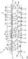
- the Fig. 1 shows a sprayer boom 12 of an agricultural sprayer 10, the agricultural sprayer 10 being designed as a field sprayer.
- the spray boom 12 has several boom segments which can be pivoted relative to one another and which allow the spray boom 12 to be folded up.
- the illustrated section of the sprayer boom 12 shows a left boom half, the sprayer boom 12 also having a right boom half.
- a plurality of application elements 14a-14k are arranged on the spray boom 12, the application elements 14a-14k being designed as spray nozzles.
- the application elements 14a-14k serve to apply the spray liquid onto the agricultural area 24.
- the agricultural sprayer 10 comprises a detection device 16 which is used to detect rows of plants 26a-26k on the agricultural area 24.
- the detection device 16 comprises several cameras 18a-18j attached to the sprayer boom 12.
- the agricultural spraying device 10 comprises an adjustment device 20, by means of which the area of impact AB of the spray liquid released by the application elements 14a-14k on the agricultural area 24 can be changed during the application process.
- the spreading elements 14a-14k, the cameras 18a-18j of the detection device 16 and the adjustment device 20 are connected to a control device which controls the adjustment device 20 as a function of the rows of plants 26a-26k detected by the detection device 16 on the agricultural area 24 during the application process.
- the adjustment device 20 has several positioning devices 22a-22d, by means of which the position of the application elements 14a-14k on the spray boom 12 can be changed.
- the positioning devices 20a-20d each have a displacement mechanism by means of which a plurality of application elements 14a-14k can be displaced along the sprayer boom 12 and thus transversely to the direction of travel of the agricultural sprayer 10.
- the displacement mechanism of the respective positioning devices 22a-22d allows individual positioning of the respective dispensing elements 14a-14k.
- the dispensing elements 14a-14k can be moved independently of one another in the adjustment directions 28a-28k shown.
- the positioning devices 22a-22d have corresponding actuators.
- the actuators can be electrical, pneumatic or hydraulic actuators.
- the positioning devices 22a-22d can be controlled in such a way that the spreading elements 14a-14k are each positioned essentially vertically above a row of plants 26a-26k during the spreading process. This allows a precise row-related application of the liquid onto the agricultural area 24.
- this can also be controlled in such a way that the spreading elements 14a-14k are each positioned above and essentially centrally between two rows of plants 26a-26k during the spreading process.
- the spray pattern of the application elements 14a-14k can also be adapted by means of the adjustment device.
- the adjusting device 20 can have adjustable or exchangeable nozzle attachments, which can be adjusted on the respective application elements 14a-14k as a function of the position or the course of the detected rows of plants 26a-26k.
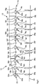
- the Fig. 2 likewise shows a sprayer boom 12 of an agricultural sprayer 10 designed as a field sprayer.
- spray device 10 several dispensing elements 14a-14k are each attached to a support structure 34a-34d, wherein the position of the support structures 34a-34d can be changed by means of the adjustment device 20.
- the carrier structures 34a-34d are displaceable in the adjustment directions 28a-28d transversely to the direction of travel.
- the movement of the support structures 34a-34d is implemented by means of corresponding actuators of the agricultural spraying device 10.
- the discharge elements 14a-14k are designed as spray nozzles.
- the support structures 34a-34d are designed as nozzle support units.
- the dispensing elements 14a-14k which are each fastened to a carrier structure 34a-34d, have an unchangeable position relative to one another. Since the application elements 14a-14k are immovably attached to the respective carrier structures 34a-34d, no exact positioning of the application elements 14a-14k above the rows of plants 26a-26k is possible despite the displaceability of the carrier structures 34a-34d in the transverse direction.
- the control device is set up to control the adjustment device 20 in such a way that the mean distance in the horizontal direction between the detected rows of plants 26a-26k and the application elements 14a assigned to the rows of plants 26a-26k -14k is minimal.
- the sum of the distances x1-x10 between the detected plant rows 26a-26k and the application elements 14a-14k respectively assigned to the plant rows 26a-26k is minimized.
- the Fig. 3 also shows a section of a sprayer boom 12 of an agricultural sprayer 10.
- the adjustment device 20 of the illustrated agricultural sprayer 10 has several pivoting devices 30a-30k, by means of which the inclination of the application elements 14a-14k on the sprayer boom 12 can be changed.
- the inclination of the individual dispensing elements 14a-14k can be set independently of one another by means of the pivoting devices 30a-30k.
- the respective pivoting devices 30a-30k have actuators by means of which the discharge elements 14a-14k can be pivoted along the pivoting directions 32a-32k.
- the control device of the agricultural spraying device 10 is set up in the illustrated embodiment, the pivoting devices 30a-30k to be controlled in such a way that the spreading elements 14a-14k are each essentially aligned with a row of plants 26a-26k during the spreading process.
- control device can also be set up to control the pivoting devices 30a-30k in such a way that the spreading elements 14a-14k are each aligned with an area between two rows of plants 26a-26k during the spreading process.
- an adjusting device 20 can also have pivoting devices 30a-30k, by means of which the inclination of the dispensing elements 14a-14k can be changed during the dispensing process.
Landscapes
- Life Sciences & Earth Sciences (AREA)
- Engineering & Computer Science (AREA)
- Insects & Arthropods (AREA)
- Pest Control & Pesticides (AREA)
- Wood Science & Technology (AREA)
- Zoology (AREA)
- Environmental Sciences (AREA)
- Catching Or Destruction (AREA)
Priority Applications (1)
| Application Number | Priority Date | Filing Date | Title |
|---|---|---|---|
| PL19401041T PL3649857T3 (pl) | 2018-10-25 | 2019-10-18 | Opryskiwacz rolniczy |
Applications Claiming Priority (1)
| Application Number | Priority Date | Filing Date | Title |
|---|---|---|---|
| DE102018126586.7A DE102018126586A1 (de) | 2018-10-25 | 2018-10-25 | Landwirtschaftliches Spritzgerät |
Publications (2)
| Publication Number | Publication Date |
|---|---|
| EP3649857A1 EP3649857A1 (de) | 2020-05-13 |
| EP3649857B1 true EP3649857B1 (de) | 2021-08-25 |
Family
ID=68503051
Family Applications (1)
| Application Number | Title | Priority Date | Filing Date |
|---|---|---|---|
| EP19401041.9A Active EP3649857B1 (de) | 2018-10-25 | 2019-10-18 | Landwirtschaftliches spritzgerät |
Country Status (4)
| Country | Link |
|---|---|
| EP (1) | EP3649857B1 (pl) |
| DE (1) | DE102018126586A1 (pl) |
| DK (1) | DK3649857T3 (pl) |
| PL (1) | PL3649857T3 (pl) |
Families Citing this family (10)
| Publication number | Priority date | Publication date | Assignee | Title |
|---|---|---|---|---|
| DE102020108500B4 (de) | 2020-03-27 | 2025-11-27 | Amazonen-Werke H. Dreyer SE & Co. KG | Landwirtschaftliches Spritzgerät und Verfahren zum Applizieren von Spritzflüssigkeit auf einer landwirtschaftlichen Nutzfläche |
| DE102020124792B4 (de) | 2020-09-23 | 2024-11-07 | Horsch Leeb Application Systems Gmbh | Landwirtschaftliche Spritzvorrichtung, Verfahren zum Ausbringen von Spritzflüssigkeit und landwirtschaftliche Feldspritze |
| BR112023018643A2 (pt) * | 2021-03-18 | 2023-10-10 | Ecorobotix Sa | Método e sistema de pulverização localizada para aplicação de alta precisão de agroquímicos |
| DE102021111357A1 (de) | 2021-05-03 | 2022-11-03 | Horsch Leeb Application Systems Gmbh | Landwirtschaftliche Feldspritze und Spritzvorrichtung für eine landwirtschaftliche Feldspritze sowie Verfahren zur Anpassung einer Spritzvorrichtung für eine reihenbezogene Ausbringung von Spritzflüssigkeit |
| DE102021121733A1 (de) | 2021-08-23 | 2023-02-23 | Amazonen-Werke H. Dreyer SE & Co. KG | Landwirtschaftliche Spritzvorrichtung und Verfahren zum Ausbringen einer Spritzflüssigkeit |
| DE102022116168A1 (de) * | 2022-06-29 | 2024-01-04 | Amazonen-Werke H. Dreyer SE & Co. KG | Verfahren zum Ausbringen von Spritzmittel auf eine landwirtschaftliche Nutzfläche mittels einer landwirtschaftlichen Spritzvorrichtung |
| DE102022121777A1 (de) | 2022-08-29 | 2024-02-29 | Horsch Leeb Application Systems Gmbh | Landwirtschaftliche Feldspritze und Spritzvorrichtung für eine landwirtschaftliche Feldspritze sowie Verfahren zur Anpassung einer Spritzvorrichtung für eine reihenbezogene Ausbringung von Spritzflüssigkeit |
| DE102022130299A1 (de) * | 2022-11-16 | 2024-05-16 | Amazonen-Werke H. Dreyer SE & Co. KG | Verfahren zum Ausbringen von Spritzmittel auf einer landwirtschaftlichen Nutzfläche und landwirtschaftliche Spritzeinrichtung |
| DE102023105538A1 (de) * | 2023-03-07 | 2024-09-12 | Amazonen-Werke H. Dreyer SE & Co. KG | Landwirtschaftliche Spritzeinrichtung |
| GB2630350A (en) * | 2023-05-25 | 2024-11-27 | Ecorobotix Sa | Controlling spot spraying of agrochemicals |
Citations (17)
| Publication number | Priority date | Publication date | Assignee | Title |
|---|---|---|---|---|
| US3959924A (en) | 1974-10-24 | 1976-06-01 | Allen Jr John Clarence | Automatic spot sprayer |
| DE2556707A1 (de) | 1974-12-31 | 1976-07-15 | Jean Marie Flix | Bearbeitungsgeraet fuer landwirtschaftliche zwecke |
| US4835691A (en) | 1987-09-11 | 1989-05-30 | Sentop Ltd. | Positioning system particularly useful for positioning agricultural implements |
| US5279068A (en) | 1991-08-19 | 1994-01-18 | Rees Steven J | Crop row deviation sensing device |
| WO1994022094A1 (en) | 1993-03-16 | 1994-09-29 | The Regents Of The University Of California | Robotic cultivator |
| DE4413739A1 (de) | 1994-04-20 | 1995-10-26 | Deutsche Forsch Luft Raumfahrt | Verfahren zum gezielten, spezifischen, dosierten Ausbringen von Nähr- und Pflegemitteln im Acker- oder Gartenbau und Einrichtung zur Durchführung des Verfahrens |
| AU668068B3 (en) | 1995-08-18 | 1996-04-18 | Rees Equipment Pty Ltd | Crop row deviation sensing device |
| WO1998016824A1 (de) | 1996-10-15 | 1998-04-23 | Heinz Ganzelmeier | Verfahren zur optischen detektion und behandlung von kulturpflanzen und nicht biologisch transformierte kulturpflanze |
| US5842307A (en) | 1996-11-15 | 1998-12-01 | May; Kenzel | Self-adjusting, automatic spot weed sprayer |
| WO2003009682A1 (en) | 2001-07-24 | 2003-02-06 | The Board Of Regents For Oklahoma State University | Nozzle attitude controller for spot and variable rate application of agricultural chemicals and fertilizers |
| DE69808434T2 (de) | 1997-12-19 | 2003-06-05 | Kuhn-Nodet S.A., Montereau | Sprühdüse |
| GB2433407A (en) | 2005-12-20 | 2007-06-27 | Nicholas Hugh Worboys | Chemical delivery system |
| EP2022329A2 (de) | 2007-08-06 | 2009-02-11 | Leeb Mechanik GmbH | Fahrbare Spritzanordnung mit einem Spritzgestänge und Verfahren zur Einstellung deren Spritzdüsen |
| US20130292487A1 (en) | 2010-09-10 | 2013-11-07 | Exel Industries | Spraying apparatus for agricultural machine with cartographic piloting |
| US20150245565A1 (en) | 2014-02-20 | 2015-09-03 | Bob Pilgrim | Device and Method for Applying Chemicals to Specific Locations on Plants |
| EP3357332A1 (en) | 2017-02-06 | 2018-08-08 | Bilberry Sas | Weed control systems and methods, agricultural sprayer |
| EP3366129A1 (de) | 2017-02-22 | 2018-08-29 | HORSCH LEEB Application Systems GmbH | Landwirtschaftliche feldspritze und verfahren zum ausbringen von flüssigen pflanzenschutzmitteln |
Family Cites Families (2)
| Publication number | Priority date | Publication date | Assignee | Title |
|---|---|---|---|---|
| ES2886865T3 (es) * | 2014-12-10 | 2021-12-21 | Univ Sydney | Sistema automático de reconocimiento y dispensación de objetivos |
| US10799903B2 (en) * | 2017-02-28 | 2020-10-13 | Deere & Company | Adjustable row unit and vehicle with adjustable row unit |
-
2018
- 2018-10-25 DE DE102018126586.7A patent/DE102018126586A1/de not_active Withdrawn
-
2019
- 2019-10-18 DK DK19401041.9T patent/DK3649857T3/da active
- 2019-10-18 PL PL19401041T patent/PL3649857T3/pl unknown
- 2019-10-18 EP EP19401041.9A patent/EP3649857B1/de active Active
Patent Citations (17)
| Publication number | Priority date | Publication date | Assignee | Title |
|---|---|---|---|---|
| US3959924A (en) | 1974-10-24 | 1976-06-01 | Allen Jr John Clarence | Automatic spot sprayer |
| DE2556707A1 (de) | 1974-12-31 | 1976-07-15 | Jean Marie Flix | Bearbeitungsgeraet fuer landwirtschaftliche zwecke |
| US4835691A (en) | 1987-09-11 | 1989-05-30 | Sentop Ltd. | Positioning system particularly useful for positioning agricultural implements |
| US5279068A (en) | 1991-08-19 | 1994-01-18 | Rees Steven J | Crop row deviation sensing device |
| WO1994022094A1 (en) | 1993-03-16 | 1994-09-29 | The Regents Of The University Of California | Robotic cultivator |
| DE4413739A1 (de) | 1994-04-20 | 1995-10-26 | Deutsche Forsch Luft Raumfahrt | Verfahren zum gezielten, spezifischen, dosierten Ausbringen von Nähr- und Pflegemitteln im Acker- oder Gartenbau und Einrichtung zur Durchführung des Verfahrens |
| AU668068B3 (en) | 1995-08-18 | 1996-04-18 | Rees Equipment Pty Ltd | Crop row deviation sensing device |
| WO1998016824A1 (de) | 1996-10-15 | 1998-04-23 | Heinz Ganzelmeier | Verfahren zur optischen detektion und behandlung von kulturpflanzen und nicht biologisch transformierte kulturpflanze |
| US5842307A (en) | 1996-11-15 | 1998-12-01 | May; Kenzel | Self-adjusting, automatic spot weed sprayer |
| DE69808434T2 (de) | 1997-12-19 | 2003-06-05 | Kuhn-Nodet S.A., Montereau | Sprühdüse |
| WO2003009682A1 (en) | 2001-07-24 | 2003-02-06 | The Board Of Regents For Oklahoma State University | Nozzle attitude controller for spot and variable rate application of agricultural chemicals and fertilizers |
| GB2433407A (en) | 2005-12-20 | 2007-06-27 | Nicholas Hugh Worboys | Chemical delivery system |
| EP2022329A2 (de) | 2007-08-06 | 2009-02-11 | Leeb Mechanik GmbH | Fahrbare Spritzanordnung mit einem Spritzgestänge und Verfahren zur Einstellung deren Spritzdüsen |
| US20130292487A1 (en) | 2010-09-10 | 2013-11-07 | Exel Industries | Spraying apparatus for agricultural machine with cartographic piloting |
| US20150245565A1 (en) | 2014-02-20 | 2015-09-03 | Bob Pilgrim | Device and Method for Applying Chemicals to Specific Locations on Plants |
| EP3357332A1 (en) | 2017-02-06 | 2018-08-08 | Bilberry Sas | Weed control systems and methods, agricultural sprayer |
| EP3366129A1 (de) | 2017-02-22 | 2018-08-29 | HORSCH LEEB Application Systems GmbH | Landwirtschaftliche feldspritze und verfahren zum ausbringen von flüssigen pflanzenschutzmitteln |
Non-Patent Citations (2)
| Title |
|---|
| "International Conference on Intelligent Information Processing , IFIP Advances in Information and Communication Technology", vol. 317, 1 January 2010, SPRINGER NEW YORK LLC , US , ISSN: 1868-4238, article REN JIANQIANG: "Nozzle Fuzzy Controller of Agricultural Spraying Robot Aiming Toward Crop Rows", pages: 198 - 206, XP055928741, DOI: 10.1007/978-3-642-12220-0_30 |
| GILES D. K., SLAUGHTER D. C.: "PRECISION BAND SPRAYING WITH MACHINE-VISION GUIDANCE AND ADJUSTABLE YAW NOZZLES.", TRANSACTIONS OF THE AMERICAN SOCIETY OF AGRICULTURAL ENGINEERS., AMERICAN SOCIETY OF AGRICULTURAL ENGINEERS. ST.JOSEPH, MI., US, vol. 40., no. 01., 1 January 1997 (1997-01-01), US , pages 29 - 36., XP000683251, ISSN: 0001-2351 |
Also Published As
| Publication number | Publication date |
|---|---|
| DK3649857T3 (da) | 2021-11-01 |
| PL3649857T3 (pl) | 2021-12-27 |
| DE102018126586A1 (de) | 2020-04-30 |
| EP3649857A1 (de) | 2020-05-13 |
Similar Documents
| Publication | Publication Date | Title |
|---|---|---|
| EP3649857B1 (de) | Landwirtschaftliches spritzgerät | |
| EP3185680B1 (de) | Landwirtschaftliche verteilmaschine mit einem system zur automatisierten ansteuerung von spritzprofilen | |
| EP3634124B1 (de) | Verteilergestänge | |
| EP3869955B1 (de) | Verfahren zum ausbringen von spritzfluessigkeit | |
| EP4094577B1 (de) | Landwirtschaftliche feldspritze und spritzvorrichtung für eine landwirtschaftliche feldspritze sowie verfahren zur anpassung einer spritzvorrichtung für eine reihenbezogene ausbringung von spritzflüssigkeit | |
| EP3869954B1 (de) | Landwirtschaftliche spritzeinrichtung | |
| EP3881660A1 (de) | Landwirtschaftliche verteileinrichtung | |
| EP3501252A1 (de) | Steuer- und/oder regelsystem, landwirtschaftliches nutzfahrzeug und verfahren zum steuern und/oder regeln eines landwirtschaftlichen nutzfahrzeugs | |
| EP3881659B1 (de) | Verfahren zum ausbringen von granularem material | |
| EP4230019B1 (de) | Pneumatischer düngerstreuer | |
| EP3881661A1 (de) | Verfahren zum ausbringen von granularem material | |
| WO2024184143A1 (de) | Landwirtschaftliche spritzeinrichtung | |
| EP3300598A1 (de) | Verfahren und spritzvorrichtung zum ausbringen einer spritzflüssigkeit auf einer landwirtschaftlichen fläche | |
| EP4218410B1 (de) | Verfahren zum ausbringen von flüssigkeit | |
| DE102019200171A1 (de) | Bodenbearbeitungsgerät | |
| EP3834612A1 (de) | Vorrichtung und verfahren zur ausbringung von spritzflüssigkeit auf einer landwirtschaftlichen fläche | |
| DE102021121733A1 (de) | Landwirtschaftliche Spritzvorrichtung und Verfahren zum Ausbringen einer Spritzflüssigkeit | |
| DE102020207529A1 (de) | Vorrichtung und Verfahren zum Ausbringen von insbesondere flüssigem Spritzmittel, Steuervorrichtung und Computerprogrammprodukt | |
| EP4371409B1 (de) | Verfahren zum ausbringen von spritzmittel auf einer landwirtschaftlichen nutzfläche und landwirtschaftliche spritzeinrichtung | |
| WO2020088948A1 (de) | Landwirtschaftliche spritzdüseneinheit | |
| EP4298904A1 (de) | Verfahren zum ausbringen von spritzmittel auf eine landwirt- schaftliche nutzfläche mittels einer landwirtschaftlichen spritzvorrichtung | |
| AT500239B1 (de) | Verfahren und sämaschine zum einbringen von fahrgassenmarkierungen in ein feld | |
| DE102022121777A1 (de) | Landwirtschaftliche Feldspritze und Spritzvorrichtung für eine landwirtschaftliche Feldspritze sowie Verfahren zur Anpassung einer Spritzvorrichtung für eine reihenbezogene Ausbringung von Spritzflüssigkeit | |
| DE102023105531A1 (de) | Landwirtschaftliche Spritzeinrichtung | |
| DE102019211905A1 (de) | Vorrichtung und Verfahren zum Dosieren von sprühfähigen Medien |
Legal Events
| Date | Code | Title | Description |
|---|---|---|---|
| PUAI | Public reference made under article 153(3) epc to a published international application that has entered the european phase |
Free format text: ORIGINAL CODE: 0009012 |
|
| STAA | Information on the status of an ep patent application or granted ep patent |
Free format text: STATUS: THE APPLICATION HAS BEEN PUBLISHED |
|
| AK | Designated contracting states |
Kind code of ref document: A1 Designated state(s): AL AT BE BG CH CY CZ DE DK EE ES FI FR GB GR HR HU IE IS IT LI LT LU LV MC MK MT NL NO PL PT RO RS SE SI SK SM TR |
|
| AX | Request for extension of the european patent |
Extension state: BA ME |
|
| STAA | Information on the status of an ep patent application or granted ep patent |
Free format text: STATUS: REQUEST FOR EXAMINATION WAS MADE |
|
| 17P | Request for examination filed |
Effective date: 20201111 |
|
| RBV | Designated contracting states (corrected) |
Designated state(s): AL AT BE BG CH CY CZ DE DK EE ES FI FR GB GR HR HU IE IS IT LI LT LU LV MC MK MT NL NO PL PT RO RS SE SI SK SM TR |
|
| RAP3 | Party data changed (applicant data changed or rights of an application transferred) |
Owner name: AMAZONEN-WERK H. DREYER SE & CO. KG |
|
| RAP3 | Party data changed (applicant data changed or rights of an application transferred) |
Owner name: AMAZONEN-WERKE H. DREYER SE & CO. KG |
|
| GRAP | Despatch of communication of intention to grant a patent |
Free format text: ORIGINAL CODE: EPIDOSNIGR1 |
|
| STAA | Information on the status of an ep patent application or granted ep patent |
Free format text: STATUS: GRANT OF PATENT IS INTENDED |
|
| INTG | Intention to grant announced |
Effective date: 20210602 |
|
| GRAS | Grant fee paid |
Free format text: ORIGINAL CODE: EPIDOSNIGR3 |
|
| GRAA | (expected) grant |
Free format text: ORIGINAL CODE: 0009210 |
|
| STAA | Information on the status of an ep patent application or granted ep patent |
Free format text: STATUS: THE PATENT HAS BEEN GRANTED |
|
| AK | Designated contracting states |
Kind code of ref document: B1 Designated state(s): AL AT BE BG CH CY CZ DE DK EE ES FI FR GB GR HR HU IE IS IT LI LT LU LV MC MK MT NL NO PL PT RO RS SE SI SK SM TR |
|
| REG | Reference to a national code |
Ref country code: CH Ref legal event code: EP |
|
| REG | Reference to a national code |
Ref country code: IE Ref legal event code: FG4D Free format text: LANGUAGE OF EP DOCUMENT: GERMAN Ref country code: AT Ref legal event code: REF Ref document number: 1422850 Country of ref document: AT Kind code of ref document: T Effective date: 20210915 |
|
| REG | Reference to a national code |
Ref country code: DE Ref legal event code: R096 Ref document number: 502019002136 Country of ref document: DE |
|
| REG | Reference to a national code |
Ref country code: DK Ref legal event code: T3 Effective date: 20211029 |
|
| REG | Reference to a national code |
Ref country code: NL Ref legal event code: FP |
|
| REG | Reference to a national code |
Ref country code: LT Ref legal event code: MG9D |
|
| PG25 | Lapsed in a contracting state [announced via postgrant information from national office to epo] |
Ref country code: LT Free format text: LAPSE BECAUSE OF FAILURE TO SUBMIT A TRANSLATION OF THE DESCRIPTION OR TO PAY THE FEE WITHIN THE PRESCRIBED TIME-LIMIT Effective date: 20210825 Ref country code: BG Free format text: LAPSE BECAUSE OF FAILURE TO SUBMIT A TRANSLATION OF THE DESCRIPTION OR TO PAY THE FEE WITHIN THE PRESCRIBED TIME-LIMIT Effective date: 20211125 Ref country code: FI Free format text: LAPSE BECAUSE OF FAILURE TO SUBMIT A TRANSLATION OF THE DESCRIPTION OR TO PAY THE FEE WITHIN THE PRESCRIBED TIME-LIMIT Effective date: 20210825 Ref country code: HR Free format text: LAPSE BECAUSE OF FAILURE TO SUBMIT A TRANSLATION OF THE DESCRIPTION OR TO PAY THE FEE WITHIN THE PRESCRIBED TIME-LIMIT Effective date: 20210825 Ref country code: PT Free format text: LAPSE BECAUSE OF FAILURE TO SUBMIT A TRANSLATION OF THE DESCRIPTION OR TO PAY THE FEE WITHIN THE PRESCRIBED TIME-LIMIT Effective date: 20211227 Ref country code: NO Free format text: LAPSE BECAUSE OF FAILURE TO SUBMIT A TRANSLATION OF THE DESCRIPTION OR TO PAY THE FEE WITHIN THE PRESCRIBED TIME-LIMIT Effective date: 20211125 Ref country code: RS Free format text: LAPSE BECAUSE OF FAILURE TO SUBMIT A TRANSLATION OF THE DESCRIPTION OR TO PAY THE FEE WITHIN THE PRESCRIBED TIME-LIMIT Effective date: 20210825 Ref country code: SE Free format text: LAPSE BECAUSE OF FAILURE TO SUBMIT A TRANSLATION OF THE DESCRIPTION OR TO PAY THE FEE WITHIN THE PRESCRIBED TIME-LIMIT Effective date: 20210825 Ref country code: ES Free format text: LAPSE BECAUSE OF FAILURE TO SUBMIT A TRANSLATION OF THE DESCRIPTION OR TO PAY THE FEE WITHIN THE PRESCRIBED TIME-LIMIT Effective date: 20210825 |
|
| PG25 | Lapsed in a contracting state [announced via postgrant information from national office to epo] |
Ref country code: LV Free format text: LAPSE BECAUSE OF FAILURE TO SUBMIT A TRANSLATION OF THE DESCRIPTION OR TO PAY THE FEE WITHIN THE PRESCRIBED TIME-LIMIT Effective date: 20210825 Ref country code: GR Free format text: LAPSE BECAUSE OF FAILURE TO SUBMIT A TRANSLATION OF THE DESCRIPTION OR TO PAY THE FEE WITHIN THE PRESCRIBED TIME-LIMIT Effective date: 20211126 |
|
| REG | Reference to a national code |
Ref country code: DE Ref legal event code: R026 Ref document number: 502019002136 Country of ref document: DE |
|
| PLBI | Opposition filed |
Free format text: ORIGINAL CODE: 0009260 |
|
| PG25 | Lapsed in a contracting state [announced via postgrant information from national office to epo] |
Ref country code: SM Free format text: LAPSE BECAUSE OF FAILURE TO SUBMIT A TRANSLATION OF THE DESCRIPTION OR TO PAY THE FEE WITHIN THE PRESCRIBED TIME-LIMIT Effective date: 20210825 Ref country code: SK Free format text: LAPSE BECAUSE OF FAILURE TO SUBMIT A TRANSLATION OF THE DESCRIPTION OR TO PAY THE FEE WITHIN THE PRESCRIBED TIME-LIMIT Effective date: 20210825 Ref country code: RO Free format text: LAPSE BECAUSE OF FAILURE TO SUBMIT A TRANSLATION OF THE DESCRIPTION OR TO PAY THE FEE WITHIN THE PRESCRIBED TIME-LIMIT Effective date: 20210825 Ref country code: EE Free format text: LAPSE BECAUSE OF FAILURE TO SUBMIT A TRANSLATION OF THE DESCRIPTION OR TO PAY THE FEE WITHIN THE PRESCRIBED TIME-LIMIT Effective date: 20210825 Ref country code: AL Free format text: LAPSE BECAUSE OF FAILURE TO SUBMIT A TRANSLATION OF THE DESCRIPTION OR TO PAY THE FEE WITHIN THE PRESCRIBED TIME-LIMIT Effective date: 20210825 |
|
| PLAB | Opposition data, opponent's data or that of the opponent's representative modified |
Free format text: ORIGINAL CODE: 0009299OPPO |
|
| PLAX | Notice of opposition and request to file observation + time limit sent |
Free format text: ORIGINAL CODE: EPIDOSNOBS2 |
|
| REG | Reference to a national code |
Ref country code: BE Ref legal event code: MM Effective date: 20211031 |
|
| 26 | Opposition filed |
Opponent name: HORSCH LEEB APPLICATION SYSTEMS GMBH Effective date: 20220525 |
|
| PG25 | Lapsed in a contracting state [announced via postgrant information from national office to epo] |
Ref country code: MC Free format text: LAPSE BECAUSE OF FAILURE TO SUBMIT A TRANSLATION OF THE DESCRIPTION OR TO PAY THE FEE WITHIN THE PRESCRIBED TIME-LIMIT Effective date: 20210825 |
|
| R26 | Opposition filed (corrected) |
Opponent name: HORSCH LEEB APPLICATION SYSTEMS GMBH Effective date: 20220525 |
|
| PG25 | Lapsed in a contracting state [announced via postgrant information from national office to epo] |
Ref country code: LU Free format text: LAPSE BECAUSE OF NON-PAYMENT OF DUE FEES Effective date: 20211018 Ref country code: IT Free format text: LAPSE BECAUSE OF FAILURE TO SUBMIT A TRANSLATION OF THE DESCRIPTION OR TO PAY THE FEE WITHIN THE PRESCRIBED TIME-LIMIT Effective date: 20210825 Ref country code: BE Free format text: LAPSE BECAUSE OF NON-PAYMENT OF DUE FEES Effective date: 20211031 |
|
| PG25 | Lapsed in a contracting state [announced via postgrant information from national office to epo] |
Ref country code: SI Free format text: LAPSE BECAUSE OF FAILURE TO SUBMIT A TRANSLATION OF THE DESCRIPTION OR TO PAY THE FEE WITHIN THE PRESCRIBED TIME-LIMIT Effective date: 20210825 |
|
| PLBB | Reply of patent proprietor to notice(s) of opposition received |
Free format text: ORIGINAL CODE: EPIDOSNOBS3 |
|
| PG25 | Lapsed in a contracting state [announced via postgrant information from national office to epo] |
Ref country code: IE Free format text: LAPSE BECAUSE OF NON-PAYMENT OF DUE FEES Effective date: 20211018 |
|
| REG | Reference to a national code |
Ref country code: CH Ref legal event code: PL |
|
| P01 | Opt-out of the competence of the unified patent court (upc) registered |
Effective date: 20230523 |
|
| PG25 | Lapsed in a contracting state [announced via postgrant information from national office to epo] |
Ref country code: CY Free format text: LAPSE BECAUSE OF FAILURE TO SUBMIT A TRANSLATION OF THE DESCRIPTION OR TO PAY THE FEE WITHIN THE PRESCRIBED TIME-LIMIT Effective date: 20210825 |
|
| PG25 | Lapsed in a contracting state [announced via postgrant information from national office to epo] |
Ref country code: LI Free format text: LAPSE BECAUSE OF NON-PAYMENT OF DUE FEES Effective date: 20221031 Ref country code: HU Free format text: LAPSE BECAUSE OF FAILURE TO SUBMIT A TRANSLATION OF THE DESCRIPTION OR TO PAY THE FEE WITHIN THE PRESCRIBED TIME-LIMIT; INVALID AB INITIO Effective date: 20191018 Ref country code: CH Free format text: LAPSE BECAUSE OF NON-PAYMENT OF DUE FEES Effective date: 20221031 |
|
| PG25 | Lapsed in a contracting state [announced via postgrant information from national office to epo] |
Ref country code: MK Free format text: LAPSE BECAUSE OF FAILURE TO SUBMIT A TRANSLATION OF THE DESCRIPTION OR TO PAY THE FEE WITHIN THE PRESCRIBED TIME-LIMIT Effective date: 20210825 |
|
| PLBP | Opposition withdrawn |
Free format text: ORIGINAL CODE: 0009264 |
|
| GBPC | Gb: european patent ceased through non-payment of renewal fee |
Effective date: 20231018 |
|
| PG25 | Lapsed in a contracting state [announced via postgrant information from national office to epo] |
Ref country code: TR Free format text: LAPSE BECAUSE OF FAILURE TO SUBMIT A TRANSLATION OF THE DESCRIPTION OR TO PAY THE FEE WITHIN THE PRESCRIBED TIME-LIMIT Effective date: 20210825 |
|
| PG25 | Lapsed in a contracting state [announced via postgrant information from national office to epo] |
Ref country code: GB Free format text: LAPSE BECAUSE OF NON-PAYMENT OF DUE FEES Effective date: 20231018 |
|
| RDAF | Communication despatched that patent is revoked |
Free format text: ORIGINAL CODE: EPIDOSNREV1 |
|
| PG25 | Lapsed in a contracting state [announced via postgrant information from national office to epo] |
Ref country code: GB Free format text: LAPSE BECAUSE OF NON-PAYMENT OF DUE FEES Effective date: 20231018 |
|
| APBP | Date of receipt of notice of appeal recorded |
Free format text: ORIGINAL CODE: EPIDOSNNOA2O |
|
| APAW | Appeal reference deleted |
Free format text: ORIGINAL CODE: EPIDOSDREFNO |
|
| PG25 | Lapsed in a contracting state [announced via postgrant information from national office to epo] |
Ref country code: MT Free format text: LAPSE BECAUSE OF FAILURE TO SUBMIT A TRANSLATION OF THE DESCRIPTION OR TO PAY THE FEE WITHIN THE PRESCRIBED TIME-LIMIT Effective date: 20210825 |
|
| APAW | Appeal reference deleted |
Free format text: ORIGINAL CODE: EPIDOSDREFNO |
|
| APBQ | Date of receipt of statement of grounds of appeal recorded |
Free format text: ORIGINAL CODE: EPIDOSNNOA3O |
|
| APAH | Appeal reference modified |
Free format text: ORIGINAL CODE: EPIDOSCREFNO |
|
| APAH | Appeal reference modified |
Free format text: ORIGINAL CODE: EPIDOSCREFNO |
|
| PGFP | Annual fee paid to national office [announced via postgrant information from national office to epo] |
Ref country code: PL Payment date: 20250912 Year of fee payment: 7 Ref country code: NL Payment date: 20250912 Year of fee payment: 7 |
|
| PGFP | Annual fee paid to national office [announced via postgrant information from national office to epo] |
Ref country code: FR Payment date: 20250908 Year of fee payment: 7 |
|
| REG | Reference to a national code |
Ref country code: AT Ref legal event code: MM01 Ref document number: 1422850 Country of ref document: AT Kind code of ref document: T Effective date: 20241018 |
|
| PGFP | Annual fee paid to national office [announced via postgrant information from national office to epo] |
Ref country code: DE Payment date: 20250902 Year of fee payment: 7 |
|
| PG25 | Lapsed in a contracting state [announced via postgrant information from national office to epo] |
Ref country code: AT Free format text: LAPSE BECAUSE OF NON-PAYMENT OF DUE FEES Effective date: 20241018 |
|
| PGFP | Annual fee paid to national office [announced via postgrant information from national office to epo] |
Ref country code: DK Payment date: 20251014 Year of fee payment: 7 |
|
| PGFP | Annual fee paid to national office [announced via postgrant information from national office to epo] |
Ref country code: CZ Payment date: 20251006 Year of fee payment: 7 |
|
| PGFP | Annual fee paid to national office [announced via postgrant information from national office to epo] |
Ref country code: AT Payment date: 20260410 Year of fee payment: 5 |