EP3649849B1 - Modulares aeroponisches system zum kultivieren, transportieren und belichten von pflanzenprodukten - Google Patents
Modulares aeroponisches system zum kultivieren, transportieren und belichten von pflanzenprodukten Download PDFInfo
- Publication number
- EP3649849B1 EP3649849B1 EP19000513.2A EP19000513A EP3649849B1 EP 3649849 B1 EP3649849 B1 EP 3649849B1 EP 19000513 A EP19000513 A EP 19000513A EP 3649849 B1 EP3649849 B1 EP 3649849B1
- Authority
- EP
- European Patent Office
- Prior art keywords
- containers
- pump
- hydraulic line
- aeroponic system
- container
- Prior art date
- Legal status (The legal status is an assumption and is not a legal conclusion. Google has not performed a legal analysis and makes no representation as to the accuracy of the status listed.)
- Active
Links
Images




Classifications
-
- A—HUMAN NECESSITIES
- A01—AGRICULTURE; FORESTRY; ANIMAL HUSBANDRY; HUNTING; TRAPPING; FISHING
- A01G—HORTICULTURE; CULTIVATION OF VEGETABLES, FLOWERS, RICE, FRUIT, VINES, HOPS OR SEAWEED; FORESTRY; WATERING
- A01G31/00—Soilless cultivation, e.g. hydroponics
- A01G31/02—Special apparatus therefor
-
- A—HUMAN NECESSITIES
- A01—AGRICULTURE; FORESTRY; ANIMAL HUSBANDRY; HUNTING; TRAPPING; FISHING
- A01G—HORTICULTURE; CULTIVATION OF VEGETABLES, FLOWERS, RICE, FRUIT, VINES, HOPS OR SEAWEED; FORESTRY; WATERING
- A01G31/00—Soilless cultivation, e.g. hydroponics
- A01G31/02—Special apparatus therefor
- A01G31/06—Hydroponic culture on racks or in stacked containers
-
- Y—GENERAL TAGGING OF NEW TECHNOLOGICAL DEVELOPMENTS; GENERAL TAGGING OF CROSS-SECTIONAL TECHNOLOGIES SPANNING OVER SEVERAL SECTIONS OF THE IPC; TECHNICAL SUBJECTS COVERED BY FORMER USPC CROSS-REFERENCE ART COLLECTIONS [XRACs] AND DIGESTS
- Y02—TECHNOLOGIES OR APPLICATIONS FOR MITIGATION OR ADAPTATION AGAINST CLIMATE CHANGE
- Y02P—CLIMATE CHANGE MITIGATION TECHNOLOGIES IN THE PRODUCTION OR PROCESSING OF GOODS
- Y02P60/00—Technologies relating to agriculture, livestock or agroalimentary industries
- Y02P60/20—Reduction of greenhouse gas [GHG] emissions in agriculture, e.g. CO2
- Y02P60/21—Dinitrogen oxide [N2O], e.g. using aquaponics, hydroponics or efficiency measures
Definitions
- the present invention refers in general to the field of production of vegetable products, for example of horticultural products such as vegetables to be eaten fresh and aromatic herbs or other varieties of plants, by soilless cultivation techniques, as well as to the distribution of said vegetable products aimed at the sale.
- the invention concerns an aeroponic system for the modular cultivation and transportation of plant products according to the appended claims.
- the present invention starts from the idea that a cultivation system that is able to allow to pick up a vegetable product from the production site, as well as to transportate it and to expose it for the sale with its root system intact, so as to maintain alive the plant, would allow the final user to have available a product in which the step of decline subsequent to collection is not yet started, so that the vital qualities and the possible organoleptical and nutritive properties thereof remain unchanged.
- the end user can therefore decide whether it is time to perform the step of collection by removing the root system of the plant, so as to keep an optimum quality of the vegetable product for a relatively long time. This would also considerably limit the waste resulting from deterioration of the vegetable products.
- the so-called "aeroponic” cultivation technique is particularly suitable for cultivation and transportation of vegetable products for sale to a final consumer.
- this known technique allows plants to be fed by nebulization means for nebulizing water enriched with mineral fertilizers, which is directly sprayed on the root system of the plants to obtain the growth of the plants in a localized environment without using soil or other granular support materials. Also, exposure of the plants to pests and pathogenic agents is substantially eliminated, and the oxygenation level of the root system of the plants is improved, which favour their development.
- the “aeroponic” cultivation technique takes advantage of the impact of the air on the plant roots to improve their development and to allow at the same time saving of water and nutrients, because their amount not absorbed directly by the roots can be recovered to be entered again in circulation in the system.
- US 2012/0085026 A1 is known an aeroponic system for cultivating plants or vegetable products, of the type defined above.
- This known system comprises a series of containers which may include more container units arranged at different heights, the containers of each unit having the bottom located at the same level.
- Each container houses inside it a nebulizer unit for nebulizing a nutritional fluid to the roots of the plants, the various containers of the system being connected with a first hydraulic line connected to the delivery side of a pump, which connects in series the containers of each container unit.
- the suction side of the pump is connected to a tank for collecting the nutritional fluid, which is placed at a lower level and is separated with respect to all the containers of the series, by means of an auxiliary hydraulic line connected to the bottom of all the containers of such a series of containers.
- a pump for each series of containers is used, as well as a plurality of first nebulization lines and more auxiliary hydraulic lines, which are independent for each series of containers.
- the object of the present invention is to propose a modular aeroponic system for cultivating, transporting and exposing vegetable products, having a particularly simple structure provided with a relatively small number of components and that allows a reduced amount of nutritional fluid to be used with respect to the aeroponic systems known up to now.
- the plurality of containers of the system comprises a main container and a series of secondary containers, the bottom of all said secondary containers being arranged at a higher level with respect to the bottom of the main container, said auxiliary hydraulic line being connected only to the bottom of the main container, and said second hydraulic line connecting with each other the bottom of all said containers.
- the system according to the invention comprises particularly simple hydraulic lines, with the benefit of reducing the manufacturing costs, which also allows separation of the various containers to be made easily in order to transportation them for the exposure in a point of sale of the vegetable products, and to reconnect them equally easily at the point of sale to keep the vegetable products alive up to the time of their pick-up by a final user.
- the main container performs the function of a collection tank for the nutritional liquid, without any need to provide a separate collection tank, the level of nutritional liquid in the secondary tanks being substantially zero, so that the system requires a minimum amount of nutritional fluid, which allows the water and the amount of the nutritional substances used by the system to be considerably saved.
- the cultivation system of the invention allows the transportability of the various modules, typically from the cultivation site to the exposure and sale site of the vegetable products, to be made easier, which enables such products to remain in the vegetative phase even during the transportation and exposure steps. In this manner, the collection step of such products is postponed to the maximum, since it takes place only by the end user after purchase.
- the system of the invention comprises a hydraulic washing circuit that includes a third hydraulic line connected to each of said containers and selectively connectable to the delivery side of the pump.
- the containers of the system can be washed in a simple and practical manner to be prepared for a new operating cycle.
- the system comprises ozonization means to ozonize said nutritional fluid, which means are connected to the inside of the main container.
- the system comprises artificial lighting means arranged above said vegetable products and associated with each of said containers.
- a first on-off valve is interposed between the delivery side of said pump and said first hydraulic line
- a second on-off valve is interposed between the delivery side of said pump and said third hydraulic line.
- first and second on-off valves consist of solenoid valves
- the operation of said pump and/or of the first and second on-off valves is managed automatically by electronic control means, which allows the pump and/or the first and the second on-off valves to be driven in an optimal manner.
- the same electronic control means are also susceptible to automatically actuate the ozonization means and/or the artificial lighting means of the system.
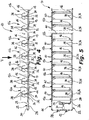
- a modular aeroponic system for cultivating, transporting and exposing vegetable products, is indicated by reference sign 10.
- the system 10 includes a series of containers arranged side by side, which can be arranged according to a linear configuration shown in Figures 1 , 4 , 7 and 8 or in a flat configuration that extends in the two spatial directions so as to be arranged side by side both longitudinally and transversely.
- Each of such containers which are generally indicated by the numeral reference 12, consists of a separable and transportable module of the system 10, which allows a plurality of vegetable products or plants 14 to be cultivated.
- the various container modules 12 have a generally box shape open at the top and are substantially closed by means of a removable upper cover 16 having a plurality of circular openings 18, for example forty-eight of these openings with reference to the figures.
- Each opening 18 is intended to removably receive a respective pot 20.
- each cover 16 is divided into four separable sections 16a, which can be removed independently from the respective container 12.
- Each of the pots 20 has perforated side surface and bottom, in order to constitute a support of the roots system of the plant 14 during its vegetative development, and it allows at the same time its roots to communicate with the inside of the respective container 12.
- the system 10 comprises a main container indicated 12a, and a series of secondary containers 12b, for example arranged so as to rest on the soil according to a linear series.
- the bottom of all the secondary containers 12b is located at a higher level with respect to the bottom of the main container 12a, for the purpose which will be explained in the following of the description.
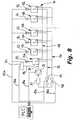
- a first hydraulic line is associated with the series of containers 12a, 12b for the purpose of nebulizing a nutritional fluid containing water and nutrients inside all the containers 12a, 12b, by means of which the plants 14 are fed through their roots.
- the hydraulic line 22 is associated with a pump 24, typically electrically controlled, the suction side of which is connected to an auxiliary hydraulic line 26 connected only to the bottom of the main container 12a.
- the delivery side of the pump 24 is connected to all the containers 12a, 12b via a further duct 28 in which a filter element 30 is interposed.
- the duct 28 is connected with all the containers 12a, 12b by respective T-shaped fittings 32 with which respective manually operable plug valves 34 are associated.
- a vertical duct 36 extends from each T-shaped fitting 32, which is connected to two curved branches 38 in turn connected to respective parallel linear ducts 40 that extend inside the containers 12a, 12b between a pair of opposite side walls of each container, each of these ducts 40 being provided with a series of nebulization nozzles not shown in detail being of a type known per se.
- a first on-off valve 42 is interposed between the delivery side of the pump 24 and the first hydraulic line 22, to connect selectively the pump 24 to the first hydraulic line 22, the valve 42 being conveniently constituted by a solenoid valve.
- a second hydraulic draining line 44 which is separated from the first hydraulic line 22, is associated with the series of containers 12a, 12b to connect the bottom of all the containers 12a, 12b by respective elbow fittings 46.
- the bottom of all the secondary containers 12b is arranged at a higher level with respect to the bottom of the main container 12a.
- spacer elements 13 are used, which are arranged below the supporting feet of the secondary containers 12b for raising the latter.
- the spacer elements 13 can be constituted by blocks of predetermined height, as shown by way of example in the figures, they are preferably of the type adjustable in height and include, for example, screw rest members provided with a threaded shank engaging a nut screw (not shown) connected to the bottom of the respective container 12b.
- the level of the bottom of the secondary containers 12b can be changed with respect to the level of the bottom of the main container 12a for the purpose that will be clarified in the following of the description.
- the spacer elements 13 of the adjustable type can be conveniently incorporated in the various support feet of the secondary containers 12b.
- a duct 48 is connected to the main container 12a only, to connect the inside thereof to an ozonizer device 50 in order to oxygenate, when this is necessary, the nutritional fluid in this main container 12a.
- the device 50 usually includes its own pump for supplying oxygen to the main tank 12a.
- artificial lighting means are associated with the various containers 12a, 12b, which are arranged above the plants 14 and comprise one or more lamps 52 for each container, with the aim of integrating or replacing natural lighting, in order to optimize the stage of growth of the plants 14.
- the system 10 is provided with a hydraulic washing circuit for washing the containers 12a, 12b, which consist of a third hydraulic line indicated 54 in the Figures.
- This hydraulic line 54 is connected to each container 12a, 12b at a hole 56 formed in a side wall thereof, preferably the side wall opposite to that adjacent to the vertical ducts 36 of the first hydraulic line 22.
- This washing circuit can be connected selectively to the delivery side of the pump 24 by a second on-off valve 58, conveniently consisting of a solenoid valve, which is interposed between the third hydraulic line 54 and the delivery side of the pump 24.
- the two on-off valves 42 and 58 are driven electrically by a programmable electronic control unit of the PLC type, in such a manner that when the valve 42 is open, during the normal operation of the first hydraulic nebulization line 22, the valve 58 connected to the third hydraulic washing line 44 is closed.
- the valve 42 of the first hydraulic nebulization line 22 is closed.
- the pump 24 and the valves 42 and 58 are connected to the electronic control unit PLC via respective conductor cables 24a, 42a and 58a.
- the ozonizer device 50 as well as the lamps 52 of the lighting means are preferably connected to the same electronic control unit PLC by a conductor cable 50a and by an electric line 52a, respectively.
- sensor means for measuring the lighting or the ambient light as well as for measuring the amount of oxygen in the nutritional fluid can be conveniently provided, which are connected to the electronic control unit PLC to control automatically the activation of the lighting means 52 and of the ozonizer device 50, when this is necessary.
- sensor means for sensing the temperature and the humidity inside the containers 12a and 12b may be provided, which are also connected to the control electronic unit PLC to monitor the environmental conditions which the roots of the plants 14 are subjected to, in order to intervene in the operation of the pump 24 and/or to activate heating elements (not shown) for heating the nutritional fluid when this is necessary, so as to maintain the optimum conditions of cultivation and growth of the plants 14.
- the valve 58 is open while the valve 42 is in the closed condition. Water is then fed inside the main container 12a to a preselected level, to start a washing step of the system 10.
- the third hydraulic line 44 of the washing circuit is in the active condition, while the first hydraulic line 22 of the nebulization circuit is inactive.
- the pump 24 By operating the pump 24, the water in the container 12a is taken from the latter by the pump 24 through the duct 26, and it is sent to all the secondary containers 12b, in addition to the same main container 12a. Owing to the principle of the communicating vessels, all the containers 12a and 12b are connected to each other by means of the second hydraulic draining line 44, and the water is present in them at the same level.
- the pump 24 is temporarily deactivated and the washing water in the container 12a is discharged to the outside of the system 10, and with it the water in the secondary containers 12b.
- the pump 24 is actuated again to start the nebulization step through the first hydraulic line 22 during the stage of growth of the plants 14.
- the plants 14 have been inserted with their pots 20 into the openings of the covers 16 of the containers 12a, 12b. In this condition, the roots of the plants 14 can absorb the nutrients necessary for their growth, from the inside of the respective containers 12a, 12b.
- the amount of nutritional fluid fed inside the main container 12a is dosed in such a manner that its level (indicated H in Figure 7 ) is substantially equal to the thickness of the spacer elements 13.
- its level indicated H in Figure 7
- this feature is important to ensure a minimum water and nutritive substance consumption by the system 10, and it is of considerable importance for the use of the system of the invention in places where there is little water.
- the demand for the nutritional fluid to be nebulized inside the various containers of the system 10 is proportional to the number of secondary containers 12b, which can vary with the need, and hence the volume of nutritional fluid in the main container 12a is also variable as a function of the number of secondary containers 12b. Therefore, the greater will be the number of secondary containers 12b, the higher the level of nutritional fluid in the main container 12. Consequently, to make the level of nutritional fluid null in the secondary containers 12b, the bottom of the latter need to be placed at a level at least equal to that of the nutritional fluid in the container 12a, which will be obtained by adjusting the height of the spacer elements 13.
- the various containers 12a, 12b of the system 10 can be taken from the site of cultivation and transported, for example by means of a truck or the like, in an exposure site such as a supermarket department, where the vegetable products 14 can be sold individually.
- the final consumer can extract a selected horticultural product 14 from the cover 16 of a container 12a, 12b placed in the exposure site, and insert the pot 20 in a support cup 21 (see Figure 3 ) for the subsequent transportation to the place of use, without any risks of damaging the roots of the plant 14.
- the support cup 21 has a radially projecting upper edge 23 designed to be snap engaged in a hollow upper edge of the pot 20 by small projections (not shown) formed inside this upper edge of the pot 20, in order to snap engage the pot 20 in the support cup 21 to retain the pot 20 engaged with the respective support cup 21.
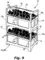
- the system of the invention can comprise supporting uprights 15 so as to allow one or more secondary containers 12b to be overlapped on a container 12a or 12b arranged below. In this manner it is possible to have two or more series of overhead containers.
- the entire system 10 thus obtained still has the characteristics described above with reference to the first embodiment, and in particular comprises a single pump 24 connected to a first hydraulic nebulization line 22 associated with the series of lower containers 12a, 12b, as well as an additional first hydraulic nebulization line 22a associated with each series of overhead containers 12b, the latter being of the same type as the secondary containers 12b of the lower series of containers.
- Both the hydraulic lines 22 and 22a of nebulization are then connected to the delivery side of the pump 24, an on-off valve 43 being interposed between the delivery side of the pump 24 and the additional hydraulic line 22a, to allow the additional hydraulic line 22a to be connected selectively with the pump 24.
- a second supplementary hydraulic draining line 44a is associated with the secondary containers 12b of the overhead series, which connects the bottom of all the overhead containers 12b, as well as an additional third hydraulic washing line 54a.
- Another on-off valve 59 is associated with the additional third hydraulic washing line 54a, which is interposed between such additional hydraulic line 54a and the delivery side of the pump 24, in order to allow this additional hydraulic line 54a to be selectively connected to the pump 24.
- valves 43 and 59 consist of solenoid valves, in order to allow to be controlled automatically by means of the programmable electronic control unit PLC.
- the lighting means of the various containers are not shown for the sake of simplicity, they are usually provided in association with the respective containers 12a, 12b in order to be able to be managed by means of the electronic control unit PLC.
- the various sensors for measuring the lighting or the ambient brightness, for measuring the amount of oxygen in the nutritional fluid, and the sensor means for sensing the temperature and the humidity inside the containers 12a and 12b can be connected to the electronic control unit PLC by means of respective conductor cables.
- the steps of the operation of the system 10 according to this embodiment are substantially the same as for the previous embodiment.
- any change and modification within the reach of the technician skilled in the art can be brought to the system of the invention, while still remaining within the scope of the accompanying claims.
Landscapes
- Life Sciences & Earth Sciences (AREA)
- Environmental Sciences (AREA)
- Cultivation Receptacles Or Flower-Pots, Or Pots For Seedlings (AREA)
- Packging For Living Organisms, Food Or Medicinal Products That Are Sensitive To Environmental Conditiond (AREA)
Claims (16)
- Aeroponisches System für die modulare Kultivierung und den Transport von Pflanzenprodukten, umfassend:- eine Vielzahl von im Wesentlichen geschlossenen Behältern (12a, 12b), die eine obere Abdeckung (16) aufweisen, in der Sitze (18) zur abnehmbaren Aufnahme von Töpfen (20) ausgebildet sind, die zur Aufnahme und zum Tragen eines jeweiligen Gartenbauprodukts (14) ausgelegt sind, wobei die Töpfe (20) Öffnungen zur Verbindung mit dem Inneren des jeweiligen Behälters (12a, 12b) aufweisen,- eine erste Hydraulikleitung (22, 22a), die mit den Behältern (12a, 12b) verbunden ist und an die Druckseite einer Förderpumpe (24) angeschlossen ist, um eine Nährflüssigkeit, die Wasser und Nährstoffe enthält, in das Innere jedes Behälters (12a, 12b) zu fördern,- eine Hilfshydraulikleitung (26), die von der ersten Hydraulikleitung getrennt ist, wobei die Hilfshydraulikleitung (26) mit der Saugseite der Pumpe (24) und mit dem Boden eines Behälters (12a) verbunden ist,wobei die Vielzahl von Behältern (12a, 12b) einen Hauptbehälter (12a) und eine Reihe von Zweitbehältern (12b) umfasst, wobei der Boden aller Zweitbehälter (12b) auf einem höheren Niveau in Bezug auf den Boden des Hauptbehälters (12a) angeordnet ist, wobei die Hilfshydraulikleitung (26) nur mit dem Boden des Hauptbehälters (12a) verbunden ist, und eine zweite Hydraulikleitung (44, 44a) den Boden aller Behälter (12a, 12b) miteinander verbindet.
- Aeroponisches System nach Anspruch 1, dadurch gekennzeichnet, dass die Zweitbehälter (12b) mittels Abstandshalterelementen (13), die unter deren Stützfüßen angeordnet sind, angehoben werden.
- Aeroponisches System nach Anspruch 2, dadurch gekennzeichnet, dass die Abstandshalterelemente (13) aus höhenverstellbaren Schraubstützelementen bestehen, die vorzugsweise in die Stützfüße der Zweitbehälter (12b) eingebaut sind.
- Aeroponisches System nach einem der Ansprüche 1 bis 3, dadurch gekennzeichnet, dass zwischen der Druckseite der Pumpe (24) und der ersten Hydraulikleitung (22, 22a) ein Filterelement (30) angeordnet ist.
- Aeroponisches System nach einem der Ansprüche 1 bis 4, dadurch gekennzeichnet, dass zwischen der Druckseite der Pumpe (24) und der ersten Hydraulikleitung (22, 22a) ein erstes Ein-Aus-Ventil (42, 43) zwischengeschaltet ist.
- Aeroponisches System nach einem der Ansprüche 1 bis 5, dadurch gekennzeichnet, dass es einen hydraulischen Waschkreislauf umfasst, der eine dritte Hydraulikleitung (54, 54a) enthält, die mit jedem der Behälter (12a, 12b) verbunden ist und selektiv mit der Druckseite der Pumpe (24) verbunden werden kann.
- Aeroponisches System nach Anspruch 6, dadurch gekennzeichnet, dass ein zweites Ein-Aus-Ventil (58, 59) zwischen der Druckseite der Pumpe (24) und der dritten Hydraulikleitung (54, 54a) angeordnet ist.
- Aeroponisches System nach einem der Ansprüche 1 bis 7, dadurch gekennzeichnet, dass es Ozonisierungsmittel (50) zum Ozonisieren der Nährflüssigkeit umfasst, die mit dem Inneren des Hauptbehälters (12a) verbunden sind.
- Aeroponisches System nach einem der Ansprüche 1 bis 8, dadurch gekennzeichnet, dass es künstliche Beleuchtungsmittel (52) umfasst, die über den Pflanzenprodukten (14) angeordnet und mit jedem der Behälter (12a, 12b) verbunden sind.
- Aeroponisches System nach einem der Ansprüche 1 bis 9, dadurch gekennzeichnet, dass das erste und das zweite Ein-Aus-Ventil (42, 43; 58, 59) aus Magnetventilen bestehen, und dass der Betrieb der Pumpe (24) und/oder des ersten und des zweiten Ein-Aus-Ventils (42, 43; 58, 59) und/oder der Ozonisierungseinrichtung (50) und/oder der künstlichen Beleuchtungsmittel (52) automatisch durch elektronische Steuermittel (PLC) gesteuert wird.
- Aeroponisches System nach einem der Ansprüche 1 bis 10, dadurch gekennzeichnet, dass es Sensormittel zum Erfassen der Temperatur und/oder der Feuchtigkeit, die in den Behältern (12a, 12b) angeordnet sind, und/oder Mittel zum Messen der Sauerstoffmenge in der Nährflüssigkeit und/oder Mittel zum Messen der Beleuchtung umfasst, wobei die Sensormittel mit den elektronischen Steuermitteln (PLC) verbunden sind, um die optimalen Bedingungen für die Kultivierung der Pflanzenprodukte (14) zu steuern, indem die Temperatur- und/oder Feuchtigkeitsbedingungen und/oder die Sauerstoffmenge in der Nährflüssigkeit und/oder die den Pflanzenprodukten (14) zugeführte Lichtmenge gesteuert werden.
- Aeroponisches System nach einem der Ansprüche 1 bis 11, dadurch gekennzeichnet, dass die Behälter (12a, 12b) mit Stützpfosten (15) versehen sind, um mindestens einen weiteren Zweitbehälter (12b) in einer Überkopfposition in Bezug auf jeden unteren Behälter (12a, 12b) zu tragen.
- Aeroponisches System nach Anspruch 12, dadurch gekennzeichnet, dass eine erste zusätzliche hydraulische Vernebelungsleitung (22a) zum Zuführen der Nährflüssigkeit, die mit der Pumpe (24) verbunden ist, und eine zweite zusätzliche hydraulische Entleerungsleitung (44a) zum Verbinden des Bodens der oben liegenden Zweitbehälter (12b), mit den oben liegenden Zweitbehältern (12b) verbunden sind.
- Aeroponisches System nach Anspruch 13, dadurch gekennzeichnet, dass ein zusätzlicher hydraulischer Waschkreislauf, der eine dritte zusätzliche hydraulische Leitung (44a) enthält, welche mit jedem der obenliegenden Behälter (12b) verbunden ist und selektiv mit der Druckseite der Pumpe (24) verbunden werden kann, mit den obenliegenden Zweitbehältern (12b) verbunden ist.
- Aeroponisches System nach Anspruch 13, dadurch gekennzeichnet, dass es ein erstes zusätzliches Ein-Aus-Ventil (43), das zwischen der Druckseite der Pumpe (24) und der ersten zusätzlichen Hydraulikleitung (22a) angeordnet ist, und ein zweites zusätzliches Ein-Aus-Ventil (59), das zwischen der Druckseite der Pumpe (24) und der dritten zusätzlichen Hydraulikleitung (54a) angeordnet ist, umfasst, wobei das erste zusätzliche Ein-Aus-Ventil (43) und das zweite zusätzliche Ein-Aus-Ventil (59) aus Magnetventilen bestehen und ihr Betrieb durch die elektronische Steuereinrichtung (PLC) gesteuert wird.
- Aeroponisches System nach einem der Ansprüche 1 bis 15, dadurch gekennzeichnet, dass die Töpfe (20), sobald sie aus dem jeweiligen Sitz (18) einer oberen Abdeckung (16) eines Behälters (12a, 12b) entfernt sind, in einen jeweiligen becherförmigen Träger (21) eingesetzt werden können, und dass der Topf (20) und der becherförmige Träger (21) gegenseitige Einrasteingriffsmittel aufweisen.
Applications Claiming Priority (1)
| Application Number | Priority Date | Filing Date | Title |
|---|---|---|---|
| IT102018000010260A IT201800010260A1 (it) | 2018-11-12 | 2018-11-12 | Sistema aeroponico modulare per la coltivazione, il trasporto e l’esposizione di prodotti vegetali |
Publications (2)
| Publication Number | Publication Date |
|---|---|
| EP3649849A1 EP3649849A1 (de) | 2020-05-13 |
| EP3649849B1 true EP3649849B1 (de) | 2021-07-21 |
Family
ID=67875836
Family Applications (1)
| Application Number | Title | Priority Date | Filing Date |
|---|---|---|---|
| EP19000513.2A Active EP3649849B1 (de) | 2018-11-12 | 2019-11-11 | Modulares aeroponisches system zum kultivieren, transportieren und belichten von pflanzenprodukten |
Country Status (3)
| Country | Link |
|---|---|
| EP (1) | EP3649849B1 (de) |
| ES (1) | ES2894635T3 (de) |
| IT (1) | IT201800010260A1 (de) |
Families Citing this family (2)
| Publication number | Priority date | Publication date | Assignee | Title |
|---|---|---|---|---|
| ES2930702B2 (es) * | 2021-06-11 | 2023-05-26 | Bohoshevych Iryna Borys | Sistema de cultivo de vegetación empotrado de fácil mantenimiento |
| CN117819067B (zh) * | 2024-03-01 | 2024-05-10 | 吉林农业科技学院 | 一种蔬菜运输储存装置 |
Family Cites Families (8)
| Publication number | Priority date | Publication date | Assignee | Title |
|---|---|---|---|---|
| CA2261815C (en) * | 1997-06-13 | 2002-09-24 | E. T. Harvest Co., Ltd. | Method for growing plants and apparatus for growing plants |
| US7861459B2 (en) * | 2007-03-19 | 2011-01-04 | General Hydroponics, Inc. | Hydroponic plant nutrient circulation/distribution system |
| US8726568B2 (en) * | 2007-11-20 | 2014-05-20 | Daniel J. Wilson | Apparatus for growing living organisms |
| US20120085026A1 (en) | 2010-10-12 | 2012-04-12 | Morris David W | Expandible aeroponic grow system |
| WO2015001763A1 (ja) * | 2013-07-01 | 2015-01-08 | パナソニックIpマネジメント株式会社 | 植物育成装置、ボックス、端部ユニット |
| JP6150413B2 (ja) * | 2014-08-13 | 2017-06-21 | 大韓民国(国立水産科学院)Republic Of Korea(National Fisheries Research And Development Institute) | アクアフォニックを利用した都心型バイオフラック養殖、及び植物栽培システム |
| CA2892131C (en) * | 2015-05-25 | 2025-08-05 | Michael C. WATSON | MURMIPONIC PLANT GROWTH SYSTEM |
| WO2018190097A1 (ja) * | 2017-04-13 | 2018-10-18 | パナソニックIpマネジメント株式会社 | 水耕栽培装置 |
-
2018
- 2018-11-12 IT IT102018000010260A patent/IT201800010260A1/it unknown
-
2019
- 2019-11-11 ES ES19000513T patent/ES2894635T3/es active Active
- 2019-11-11 EP EP19000513.2A patent/EP3649849B1/de active Active
Non-Patent Citations (1)
| Title |
|---|
| None * |
Also Published As
| Publication number | Publication date |
|---|---|
| ES2894635T3 (es) | 2022-02-15 |
| EP3649849A1 (de) | 2020-05-13 |
| IT201800010260A1 (it) | 2020-05-12 |
Similar Documents
| Publication | Publication Date | Title |
|---|---|---|
| US5555676A (en) | Vertical planter apparatus and method | |
| US11751516B2 (en) | Method for the automated operation of a greenhouse, supply facility and automated greenhouse | |
| JPH05192046A (ja) | 植物栽培装置 | |
| EP3837967A1 (de) | Gerät für die aeroponic kultivation von pflanz produkten | |
| US12514178B2 (en) | Automated hydroponic growing appliance | |
| EP3649849A1 (de) | Modulares aeroponisches system zum kultivieren, transportieren und belichten von pflanzenprodukten | |
| KR20140057482A (ko) | 다단식 실내 경작방법과 장치 | |
| KR20160131522A (ko) | 청사료 및 식물 자동수경재배 시스템 및 그 제어방법 | |
| US20250160264A1 (en) | Automatic warehouse for indoor cultivations and relative cultivation method | |
| WO2022015752A1 (en) | Automated hydroponic growing appliance | |
| KR101303247B1 (ko) | 착탈식 화분이 구비된 수경재배장치 | |
| KR102400629B1 (ko) | 식물 재배 장치 | |
| KR20240023597A (ko) | 식물들의 생육을 위한 수직 재배 시스템 및 식물들의 생육을 위한 방법 | |
| WO2018078354A1 (en) | A system and method for growing root vegetables | |
| CN107896970A (zh) | 分布式智能植物工厂 | |
| CA2869475A1 (en) | Modular integrated system for seed germination, cultivation, planting, fertilizing and maintenance of plants | |
| KR101577275B1 (ko) | 친환경 새싹사료 대량 생산장치 | |
| KR101561658B1 (ko) | 녹색 두채류를 포함한 새싹 재배장치 | |
| US12356907B2 (en) | Inverted plant growth and selection system and method of use | |
| KR102265063B1 (ko) | 화분 삽입용 박스 모듈 | |
| KR20230119338A (ko) | 수생식물 재배장치 | |
| CA2118397C (en) | Method and apparatus for integrated pre-cultivation and ultimate cultivation of plants | |
| JP2022044578A (ja) | 垂直栽培装置及び垂直栽培の方法 | |
| CN116782760A (zh) | 用于在室内使用的模块化水培系统 | |
| KR20000000712A (ko) | 콩나물의 자동재배장치 |
Legal Events
| Date | Code | Title | Description |
|---|---|---|---|
| PUAI | Public reference made under article 153(3) epc to a published international application that has entered the european phase |
Free format text: ORIGINAL CODE: 0009012 |
|
| STAA | Information on the status of an ep patent application or granted ep patent |
Free format text: STATUS: THE APPLICATION HAS BEEN PUBLISHED |
|
| AK | Designated contracting states |
Kind code of ref document: A1 Designated state(s): AL AT BE BG CH CY CZ DE DK EE ES FI FR GB GR HR HU IE IS IT LI LT LU LV MC MK MT NL NO PL PT RO RS SE SI SK SM TR |
|
| AX | Request for extension of the european patent |
Extension state: BA ME |
|
| STAA | Information on the status of an ep patent application or granted ep patent |
Free format text: STATUS: REQUEST FOR EXAMINATION WAS MADE |
|
| 17P | Request for examination filed |
Effective date: 20201029 |
|
| RBV | Designated contracting states (corrected) |
Designated state(s): AL AT BE BG CH CY CZ DE DK EE ES FI FR GB GR HR HU IE IS IT LI LT LU LV MC MK MT NL NO PL PT RO RS SE SI SK SM TR |
|
| RIC1 | Information provided on ipc code assigned before grant |
Ipc: A01G 31/02 20060101AFI20201130BHEP Ipc: A01G 31/06 20060101ALI20201130BHEP |
|
| GRAP | Despatch of communication of intention to grant a patent |
Free format text: ORIGINAL CODE: EPIDOSNIGR1 |
|
| STAA | Information on the status of an ep patent application or granted ep patent |
Free format text: STATUS: GRANT OF PATENT IS INTENDED |
|
| INTG | Intention to grant announced |
Effective date: 20210128 |
|
| GRAS | Grant fee paid |
Free format text: ORIGINAL CODE: EPIDOSNIGR3 |
|
| GRAA | (expected) grant |
Free format text: ORIGINAL CODE: 0009210 |
|
| STAA | Information on the status of an ep patent application or granted ep patent |
Free format text: STATUS: THE PATENT HAS BEEN GRANTED |
|
| RAP3 | Party data changed (applicant data changed or rights of an application transferred) |
Owner name: AGRICOOLTUR S.R.L. |
|
| AK | Designated contracting states |
Kind code of ref document: B1 Designated state(s): AL AT BE BG CH CY CZ DE DK EE ES FI FR GB GR HR HU IE IS IT LI LT LU LV MC MK MT NL NO PL PT RO RS SE SI SK SM TR |
|
| REG | Reference to a national code |
Ref country code: GB Ref legal event code: FG4D |
|
| REG | Reference to a national code |
Ref country code: CH Ref legal event code: EP |
|
| REG | Reference to a national code |
Ref country code: DE Ref legal event code: R096 Ref document number: 602019006153 Country of ref document: DE |
|
| REG | Reference to a national code |
Ref country code: AT Ref legal event code: REF Ref document number: 1411723 Country of ref document: AT Kind code of ref document: T Effective date: 20210815 |
|
| REG | Reference to a national code |
Ref country code: IE Ref legal event code: FG4D |
|
| REG | Reference to a national code |
Ref country code: NL Ref legal event code: FP Ref country code: LT Ref legal event code: MG9D |
|
| REG | Reference to a national code |
Ref country code: AT Ref legal event code: MK05 Ref document number: 1411723 Country of ref document: AT Kind code of ref document: T Effective date: 20210721 |
|
| PG25 | Lapsed in a contracting state [announced via postgrant information from national office to epo] |
Ref country code: RS Free format text: LAPSE BECAUSE OF FAILURE TO SUBMIT A TRANSLATION OF THE DESCRIPTION OR TO PAY THE FEE WITHIN THE PRESCRIBED TIME-LIMIT Effective date: 20210721 Ref country code: SE Free format text: LAPSE BECAUSE OF FAILURE TO SUBMIT A TRANSLATION OF THE DESCRIPTION OR TO PAY THE FEE WITHIN THE PRESCRIBED TIME-LIMIT Effective date: 20210721 Ref country code: FI Free format text: LAPSE BECAUSE OF FAILURE TO SUBMIT A TRANSLATION OF THE DESCRIPTION OR TO PAY THE FEE WITHIN THE PRESCRIBED TIME-LIMIT Effective date: 20210721 Ref country code: LT Free format text: LAPSE BECAUSE OF FAILURE TO SUBMIT A TRANSLATION OF THE DESCRIPTION OR TO PAY THE FEE WITHIN THE PRESCRIBED TIME-LIMIT Effective date: 20210721 Ref country code: AT Free format text: LAPSE BECAUSE OF FAILURE TO SUBMIT A TRANSLATION OF THE DESCRIPTION OR TO PAY THE FEE WITHIN THE PRESCRIBED TIME-LIMIT Effective date: 20210721 Ref country code: BG Free format text: LAPSE BECAUSE OF FAILURE TO SUBMIT A TRANSLATION OF THE DESCRIPTION OR TO PAY THE FEE WITHIN THE PRESCRIBED TIME-LIMIT Effective date: 20211021 Ref country code: HR Free format text: LAPSE BECAUSE OF FAILURE TO SUBMIT A TRANSLATION OF THE DESCRIPTION OR TO PAY THE FEE WITHIN THE PRESCRIBED TIME-LIMIT Effective date: 20210721 Ref country code: PT Free format text: LAPSE BECAUSE OF FAILURE TO SUBMIT A TRANSLATION OF THE DESCRIPTION OR TO PAY THE FEE WITHIN THE PRESCRIBED TIME-LIMIT Effective date: 20211122 Ref country code: NO Free format text: LAPSE BECAUSE OF FAILURE TO SUBMIT A TRANSLATION OF THE DESCRIPTION OR TO PAY THE FEE WITHIN THE PRESCRIBED TIME-LIMIT Effective date: 20211021 |
|
| REG | Reference to a national code |
Ref country code: ES Ref legal event code: FG2A Ref document number: 2894635 Country of ref document: ES Kind code of ref document: T3 Effective date: 20220215 |
|
| PG25 | Lapsed in a contracting state [announced via postgrant information from national office to epo] |
Ref country code: PL Free format text: LAPSE BECAUSE OF FAILURE TO SUBMIT A TRANSLATION OF THE DESCRIPTION OR TO PAY THE FEE WITHIN THE PRESCRIBED TIME-LIMIT Effective date: 20210721 Ref country code: LV Free format text: LAPSE BECAUSE OF FAILURE TO SUBMIT A TRANSLATION OF THE DESCRIPTION OR TO PAY THE FEE WITHIN THE PRESCRIBED TIME-LIMIT Effective date: 20210721 Ref country code: GR Free format text: LAPSE BECAUSE OF FAILURE TO SUBMIT A TRANSLATION OF THE DESCRIPTION OR TO PAY THE FEE WITHIN THE PRESCRIBED TIME-LIMIT Effective date: 20211022 |
|
| REG | Reference to a national code |
Ref country code: DE Ref legal event code: R097 Ref document number: 602019006153 Country of ref document: DE |
|
| PG25 | Lapsed in a contracting state [announced via postgrant information from national office to epo] |
Ref country code: DK Free format text: LAPSE BECAUSE OF FAILURE TO SUBMIT A TRANSLATION OF THE DESCRIPTION OR TO PAY THE FEE WITHIN THE PRESCRIBED TIME-LIMIT Effective date: 20210721 |
|
| PLBE | No opposition filed within time limit |
Free format text: ORIGINAL CODE: 0009261 |
|
| STAA | Information on the status of an ep patent application or granted ep patent |
Free format text: STATUS: NO OPPOSITION FILED WITHIN TIME LIMIT |
|
| PG25 | Lapsed in a contracting state [announced via postgrant information from national office to epo] |
Ref country code: SM Free format text: LAPSE BECAUSE OF FAILURE TO SUBMIT A TRANSLATION OF THE DESCRIPTION OR TO PAY THE FEE WITHIN THE PRESCRIBED TIME-LIMIT Effective date: 20210721 Ref country code: SK Free format text: LAPSE BECAUSE OF FAILURE TO SUBMIT A TRANSLATION OF THE DESCRIPTION OR TO PAY THE FEE WITHIN THE PRESCRIBED TIME-LIMIT Effective date: 20210721 Ref country code: RO Free format text: LAPSE BECAUSE OF FAILURE TO SUBMIT A TRANSLATION OF THE DESCRIPTION OR TO PAY THE FEE WITHIN THE PRESCRIBED TIME-LIMIT Effective date: 20210721 Ref country code: EE Free format text: LAPSE BECAUSE OF FAILURE TO SUBMIT A TRANSLATION OF THE DESCRIPTION OR TO PAY THE FEE WITHIN THE PRESCRIBED TIME-LIMIT Effective date: 20210721 Ref country code: CZ Free format text: LAPSE BECAUSE OF FAILURE TO SUBMIT A TRANSLATION OF THE DESCRIPTION OR TO PAY THE FEE WITHIN THE PRESCRIBED TIME-LIMIT Effective date: 20210721 Ref country code: AL Free format text: LAPSE BECAUSE OF FAILURE TO SUBMIT A TRANSLATION OF THE DESCRIPTION OR TO PAY THE FEE WITHIN THE PRESCRIBED TIME-LIMIT Effective date: 20210721 |
|
| 26N | No opposition filed |
Effective date: 20220422 |
|
| PG25 | Lapsed in a contracting state [announced via postgrant information from national office to epo] |
Ref country code: LU Free format text: LAPSE BECAUSE OF NON-PAYMENT OF DUE FEES Effective date: 20211111 |
|
| PG25 | Lapsed in a contracting state [announced via postgrant information from national office to epo] |
Ref country code: IE Free format text: LAPSE BECAUSE OF NON-PAYMENT OF DUE FEES Effective date: 20211111 |
|
| PG25 | Lapsed in a contracting state [announced via postgrant information from national office to epo] |
Ref country code: CY Free format text: LAPSE BECAUSE OF FAILURE TO SUBMIT A TRANSLATION OF THE DESCRIPTION OR TO PAY THE FEE WITHIN THE PRESCRIBED TIME-LIMIT Effective date: 20210721 |
|
| P01 | Opt-out of the competence of the unified patent court (upc) registered |
Effective date: 20230603 |
|
| PG25 | Lapsed in a contracting state [announced via postgrant information from national office to epo] |
Ref country code: HU Free format text: LAPSE BECAUSE OF FAILURE TO SUBMIT A TRANSLATION OF THE DESCRIPTION OR TO PAY THE FEE WITHIN THE PRESCRIBED TIME-LIMIT; INVALID AB INITIO Effective date: 20191111 |
|
| PG25 | Lapsed in a contracting state [announced via postgrant information from national office to epo] |
Ref country code: MK Free format text: LAPSE BECAUSE OF FAILURE TO SUBMIT A TRANSLATION OF THE DESCRIPTION OR TO PAY THE FEE WITHIN THE PRESCRIBED TIME-LIMIT Effective date: 20210721 |
|
| PG25 | Lapsed in a contracting state [announced via postgrant information from national office to epo] |
Ref country code: MT Free format text: LAPSE BECAUSE OF FAILURE TO SUBMIT A TRANSLATION OF THE DESCRIPTION OR TO PAY THE FEE WITHIN THE PRESCRIBED TIME-LIMIT Effective date: 20210721 |
|
| REG | Reference to a national code |
Ref country code: CH Ref legal event code: U11 Free format text: ST27 STATUS EVENT CODE: U-0-0-U10-U11 (AS PROVIDED BY THE NATIONAL OFFICE) Effective date: 20251201 |
|
| PG25 | Lapsed in a contracting state [announced via postgrant information from national office to epo] |
Ref country code: TR Free format text: LAPSE BECAUSE OF FAILURE TO SUBMIT A TRANSLATION OF THE DESCRIPTION OR TO PAY THE FEE WITHIN THE PRESCRIBED TIME-LIMIT Effective date: 20210721 |
|
| PGFP | Annual fee paid to national office [announced via postgrant information from national office to epo] |
Ref country code: NL Payment date: 20251124 Year of fee payment: 7 |
|
| PGFP | Annual fee paid to national office [announced via postgrant information from national office to epo] |
Ref country code: DE Payment date: 20251118 Year of fee payment: 7 |
|
| PGFP | Annual fee paid to national office [announced via postgrant information from national office to epo] |
Ref country code: GB Payment date: 20251112 Year of fee payment: 7 |
|
| PGFP | Annual fee paid to national office [announced via postgrant information from national office to epo] |
Ref country code: MC Payment date: 20251126 Year of fee payment: 7 |
|
| PGFP | Annual fee paid to national office [announced via postgrant information from national office to epo] |
Ref country code: IT Payment date: 20251124 Year of fee payment: 7 |
|
| PGFP | Annual fee paid to national office [announced via postgrant information from national office to epo] |
Ref country code: FR Payment date: 20251120 Year of fee payment: 7 |
|
| PGFP | Annual fee paid to national office [announced via postgrant information from national office to epo] |
Ref country code: BE Payment date: 20251124 Year of fee payment: 7 |
|
| PGFP | Annual fee paid to national office [announced via postgrant information from national office to epo] |
Ref country code: CH Payment date: 20251201 Year of fee payment: 7 |
|
| PGFP | Annual fee paid to national office [announced via postgrant information from national office to epo] |
Ref country code: ES Payment date: 20251203 Year of fee payment: 7 |