EP3649845A1 - Mécanisme rabattable de couplage de vis sans fin - Google Patents
Mécanisme rabattable de couplage de vis sans fin Download PDFInfo
- Publication number
- EP3649845A1 EP3649845A1 EP19206329.5A EP19206329A EP3649845A1 EP 3649845 A1 EP3649845 A1 EP 3649845A1 EP 19206329 A EP19206329 A EP 19206329A EP 3649845 A1 EP3649845 A1 EP 3649845A1
- Authority
- EP
- European Patent Office
- Prior art keywords
- auger
- axis
- housing
- drive
- coupler
- Prior art date
- Legal status (The legal status is an assumption and is not a legal conclusion. Google has not performed a legal analysis and makes no representation as to the accuracy of the status listed.)
- Granted
Links
Images


Classifications
-
- B—PERFORMING OPERATIONS; TRANSPORTING
- B65—CONVEYING; PACKING; STORING; HANDLING THIN OR FILAMENTARY MATERIAL
- B65G—TRANSPORT OR STORAGE DEVICES, e.g. CONVEYORS FOR LOADING OR TIPPING, SHOP CONVEYOR SYSTEMS OR PNEUMATIC TUBE CONVEYORS
- B65G33/00—Screw or rotary spiral conveyors
- B65G33/24—Details
- B65G33/26—Screws
-
- A—HUMAN NECESSITIES
- A01—AGRICULTURE; FORESTRY; ANIMAL HUSBANDRY; HUNTING; TRAPPING; FISHING
- A01D—HARVESTING; MOWING
- A01D41/00—Combines, i.e. harvesters or mowers combined with threshing devices
- A01D41/12—Details of combines
- A01D41/1208—Tanks for grain or chaff
- A01D41/1217—Unloading mechanisms
-
- A—HUMAN NECESSITIES
- A01—AGRICULTURE; FORESTRY; ANIMAL HUSBANDRY; HUNTING; TRAPPING; FISHING
- A01D—HARVESTING; MOWING
- A01D41/00—Combines, i.e. harvesters or mowers combined with threshing devices
- A01D41/12—Details of combines
-
- A—HUMAN NECESSITIES
- A01—AGRICULTURE; FORESTRY; ANIMAL HUSBANDRY; HUNTING; TRAPPING; FISHING
- A01F—PROCESSING OF HARVESTED PRODUCE; HAY OR STRAW PRESSES; DEVICES FOR STORING AGRICULTURAL OR HORTICULTURAL PRODUCE
- A01F12/00—Parts or details of threshing apparatus
- A01F12/46—Mechanical grain conveyors
-
- B—PERFORMING OPERATIONS; TRANSPORTING
- B65—CONVEYING; PACKING; STORING; HANDLING THIN OR FILAMENTARY MATERIAL
- B65G—TRANSPORT OR STORAGE DEVICES, e.g. CONVEYORS FOR LOADING OR TIPPING, SHOP CONVEYOR SYSTEMS OR PNEUMATIC TUBE CONVEYORS
- B65G33/00—Screw or rotary spiral conveyors
- B65G33/24—Details
- B65G33/32—Adaptations of bearings or couplings for supporting and connecting screws
-
- A—HUMAN NECESSITIES
- A01—AGRICULTURE; FORESTRY; ANIMAL HUSBANDRY; HUNTING; TRAPPING; FISHING
- A01D—HARVESTING; MOWING
- A01D61/00—Elevators or conveyors for binders or combines
-
- B—PERFORMING OPERATIONS; TRANSPORTING
- B65—CONVEYING; PACKING; STORING; HANDLING THIN OR FILAMENTARY MATERIAL
- B65G—TRANSPORT OR STORAGE DEVICES, e.g. CONVEYORS FOR LOADING OR TIPPING, SHOP CONVEYOR SYSTEMS OR PNEUMATIC TUBE CONVEYORS
- B65G33/00—Screw or rotary spiral conveyors
- B65G33/08—Screw or rotary spiral conveyors for fluent solid materials
- B65G33/14—Screw or rotary spiral conveyors for fluent solid materials comprising a screw or screws enclosed in a tubular housing
Definitions
- an agricultural machine typically has an auger that is used to unload grain from a grain tank on the combine to an external grain cart or other receptacle.
- a typical auger includes an auger screw located inside a cylindrical housing. Rotation of the auger screw carries grain or other material along the length of the housing until it is expelled out the end of the housing.
- the auger it is desirable for the auger to be retractable to protect the auger when it is not in use and to allow the equipment to be more maneuverable and to navigate through smaller spaces.
- Retractable augers have been provided in various configurations. For example, it is known to make the auger screw and housing as a unitary assembly that can be pivoted relative to the combine to place the auger alongside the combine's body. In this case, the entire length of the auger may be moved as a single unit relative to the rest of the equipment.
- the auger includes a folding joint connecting a first auger screw and its associated housing with a second auger screw and its associated housing. Examples of such devices are shown in U.S. Pat. Nos. 8,033,377 ; 8,827,782 ; 7,494,409 ; 7,367,881 ; 7,287,639 and 7,168,554 .
- a folding auger system has been provided with a mechanism to help align the two auger screws when the system is unfolded for use.
- a driving auger has a drive cog mounted on a spring to allow the drive cog to retract if it is aligned directly with the driven cog of the driven auger during unfolding. Subsequent rotation of the driving auger turns the driving cog, and the spring extends to move the driving cog so that the driven cog is in the rotation path of the driving cog.
- 7,494,409 shows a drive auger having a ball-shaped drive cog, and a driven auger having a cylindrical receptacle for receiving the drive cog and aligning the two auger screws during unfolding.
- the receptacle has a driven cog mounted therein, and the drive cog is mounted on springs that allow it to retract somewhat if the drive cog's teeth are not perfectly aligned with the driven cog's teeth during initial engagement.
- U.S. Pat. No. 7,287,639 shows an entire auger screw being mounted to shift axially to accommodate misalignment during unfolding.
- a first drive coupler is located at a distal end of the first auger screw and offset from the first axis.
- a drive sleeve is located at a proximal end of the second auger screw and rigidly connected to the second auger screw, the drive sleeve comprising at least one slot offset from and extending parallel to the second axis.
- a second drive coupler is located at the proximal end of the second auger screw and offset from the second axis, the second drive coupler extending into the slot and being movable within the slot parallel to the second axis between a first coupler position in which the second drive coupler is in driving connection with the first drive coupler when the second housing is in the second position, and a second coupler position in which the second drive coupler is not in driving connection with the first drive coupler when the second housing is in the second position.
- an agricultural combine having a grain hopper and a foldable auger operatively connected to the grain hopper.
- the foldable auger has a first auger assembly comprising a first housing extending along a first axis, and a first auger screw mounted within the first housing to rotate about the first axis, a second auger assembly comprising a second housing extending along a second axis, and a second auger screw mounted within the second housing to rotate about the second axis, and a pivot joining a distal end of the first housing to a proximal end of the second housing, the pivot being configured to permit the second auger assembly to move relative to the first auger assembly between a first housing position in which the second axis is not coaxially aligned with the first axis, and a second housing position in which the second axis is coaxially aligned with the first axis.
- a first drive coupler is located at a distal end of the first auger screw and offset from the first axis.
- a drive sleeve is located at a proximal end of the second auger screw and rigidly connected to the second auger screw, the drive sleeve comprising at least one slot offset from and extending parallel to the second axis.
- a second drive coupler is located at the proximal end of the second auger screw and offset from the second axis, the second drive coupler extending into the slot and being movable within the slot parallel to the second axis between a first coupler position in which the second drive coupler is in driving connection with the first drive coupler when the second housing is in the second position, and a second coupler position in which the second drive coupler is not in driving connection with the first drive coupler when the second housing is in the second position.
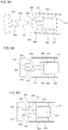
- FIGs. 1A through 3 illustrate a first exemplary embodiment of a foldable auger 100.
- the auger 100 has a first auger assembly 102 that is movably connected to a second auger assembly 104.
- one of the two auger assemblies 102, 104 will be rigidly fixed to the frame or structure of a vehicle, such as a combine, and the other will be mounted to be movable relative to the vehicle frame or structure.
- the fixed auger assembly is sometimes referred to as an "inner” auger assembly
- the movable auger assembly is sometimes referred to as an "outer" auger assembly.
- both of the auger assemblies 102, 104 might be movably attached to the vehicle.
- the second auger assembly 104 includes a second housing 116 that extends along a second axis 118 from a proximal end 120 of the second auger assembly 104 to a distal end 122 of the second auger assembly 104.
- a second auger screw 124 is mounted within the second housing 116 on one or more bearings, such that it can rotate about the second axis 118. Such rotation will cause grain inside the second housing 116 to advance along the second auger assembly 104, as known in the art.
- a pivot 126 connects the distal end 112 of the first auger assembly 102 to the proximal end 120 of the second auger assembly 104.
- the pivot 126 may be any suitable connection that allows the first auger assembly 102 and the second auger assembly 104 to move relative to one another between a first housing position in which the second axis 118 is not aligned with the first axis 108 (see, e.g., FIG. 1B ), and a second housing position in which the second axis 118 is coaxially aligned with the first axis 108 (see, e.g., FIG. 1A ).
- the pivot 126 may be a pin joint that directly connects the first auger assembly 102 to the second auger assembly 104 via a common pin 200, for rotation about the pin's axis.
- the pivot 126 may comprise a virtual pivot mechanism, such as a linkage that causes the second auger assembly 104 to rotate or move about a fixed or moving virtual pivot location.
- the pivot 126 is described herein as permitting the second auger assembly 104 to move relative to the first auger assembly 102, and this will be understood to encompass situations in which either the first auger assembly 102 or the second auger assembly 104 is fixed relative to a vehicle or other structure.
- Any suitable operation mechanism may be provided to cause the first auger assembly 102 and the second auger assembly 104 to rotate relative to one another.
- a hydraulic piston 128 may be used to operate a linkage 130 that interconnects the first auger assembly 102 and the second auger assembly, such as shown in FIGs. 1A and 1B .
- Other alternatives and variations will be apparent to persons of ordinary skill in the art in view of the present disclosure, and any such mechanism may be used to move the parts between the first housing position and the second housing position.
- the two assemblies are not aligned with one another, and are in a folded state. In this condition, the auger assemblies 102, 104 do not form a continuous path for conveying grain or the like. This position may be adopted to store the foldable auger 100 when it is not in use.
- the distal end of the first housing 106 contacts the proximal end of the second housing 116 to form a continuous enclosed passage for conveying grain or the like.
- One or both of the housings 106, 116 may include a seal 202, such as a flexible rubber seal or the like, to provide a more impermeable connection, such as known in the art.
- the first auger screw 114 engages the second auger screw 124 to form a continuous auger screw for moving grain or the like along the auger 100.
- a drive coupler system is provided between the first auger screw 114 and the second auger screw 124, so that the two auger screws 114, 124 can be moved in unison upon application of an operating torque by a motor 132.
- the motor 132 is operatively connected to the first auger screw 114 to apply an operating torque to the first auger screw regardless of the position of the second auger assembly 104.
- the first auger screw 114 can transmit the operating torque (or at least a portion thereof, as some might be lost through friction or other typical driveline losses) from the motor 132 to the second auger screw 124.
- motor 132 will be replaced by motor 132' driving the second auger screw 124.
- Any driving connection may be provided between the motor 132, 132' and the respective auger screw 114, 124.
- a torque-transmitting connection may be provided in the form of belts and pulleys, meshing gears, or a simple direct drive connection.
- Other devices, such as a clutch, transmission, speed controls and so on may also be used to operate the motor 132 and drive the auger screws 114, 124.
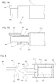
- the second drive coupler 206 sweeps through its own circular path that is offset from the second axis 118 as the second auger screw 124 rotates.
- the circular path of the first drive coupler 204 overlaps with the circular path of the second drive coupler 206 when the second auger assembly 104 is in the second housing position.
- the first and second drive couplers 204, 206 engage one another transmit the operating torque between the first and second auger screws 114, 124.
- the first drive coupler 204 may be connected to rotate with the first auger screw 114 using any conventional connection.
- the first drive coupler 204 may comprise a rigid structure that is bolted to or otherwise rigidly attached to the central shaft 208 of the first auger screw 114.
- the first drive coupler 204 also may include a mechanism to help center the first auger screw 114 on the second auger screw 124, such as a centering post 210 that extends along the first axis 108.
- the centering post 210 may terminate at a tapered distal tip to help accommodate for misalignment of the part during movement from the first housing position to the second housing position.
- the second drive coupler 206 is connected to rotate with the second auger screw 124 by a drive sleeve 212, which is rigidly connected to a central shaft 214 of the second auger screw 124. Details of exemplary drive sleeves 212 are discussed in more detail below.
- the second drive coupler 206 also may include a mechanism to help center the second auger screw 124 on the first auger screw 114, such as a centering post receptacle 216 that extends along the second axis 118 and is shaped to receive the centering post 210 when the parts are in the second housing position.
- the centering post receptacle 216 may have a tapered inlet to help accommodate for misalignment when the parts are moved into the second housing position.
- the drive sleeve 212 may have a threaded outer surface that engages threads formed internally to the hollow central shaft 214, or it may be welded, brazed or clamped into place.
- the drive sleeve 212 also may be attached to a proximal end of the second auger screw 124. The rigid connection between the drive sleeve 212 and the second auger screw 124 prevents the drive sleeve 212 from rotating relative to the second auger screw 124.
- the drive sleeve 212 may be formed as an annular ring having a central opening 402 and the slot 300 may be formed as a gap in the annular ring that extends entirely from the outer perimeter of the ring to the central opening 402.
- the slot 300 may extend only partially through the annular ring, or be formed as an axial hole in the annular ring.
- the drive sleeve 212 may not have an annular central opening 402. For example, in the embodiment of FIG.
- At least a portion of the second drive coupler 206 is located at a radial offset distance from the second axis 118 that overlaps the location of the slot 300.
- the second drive coupler 206 is captured within the slot 300 such that it cannot move about the second axis 118 without pressing laterally against the slot 300 walls to apply a rotation torque to turn the second auger screw 124.
- the second drive coupler 206 is also slidable within the slot 300, in a direction parallel to the second axis 118, between a first coupler position (see, e.g., FIGs. 5 , 6A and 6C ) and second coupler position (see, e.g., FIG. 6B ).
- first coupler position the second drive coupler 206 is displaced in the proximal direction from the second auger screw 124.
- the second drive coupler 206 is displaced in the distal direction relative to the first coupler position (i.e., it is moved distally with respect to the second auger screw 124).
- the sliding connection between the second drive coupler 206 and the drive sleeve 212 may include one or more sliding bearings or bushings to allow smooth movement between the parts.
- the second drive coupler 206 is connected to a slider 304 (which may have a centering post receptacle 216 located therein), which may be located along the second axis 118.
- the slider 304 passes through the annular opening 402 in the drive sleeve 212, and the abutting faces of the slider 304 and annular opening 402 may include suitable bearing surfaces (e.g., bushing material or the like) to provide low friction contact therebetween.
- suitable bearing surfaces e.g., bushing material or the like
- the slider 304 has a cylindrical outer wall that matches the annular opening 402, but this is not strictly required.
- the slider 304 may have a square cross-sectional profile as viewed along the second axis 118, and the annular opening 402 may be replaced by a similarly-shaped square opening.
- Other alternatives and variations will be apparent to persons of ordinary skill in the art in view of the present disclosure.
- One or more mechanisms may be provided to bias the second drive coupler 206 towards the first coupler position.
- one or more springs 308 may be provided between facing surfaces of the second drive coupler 206 and the second auger screw 124 to generate a resilient biasing force that allows the second drive coupler 206 to slide to the second coupler position application of a force to compress the spring 308, but returns the second drive coupler 206 to the first coupler position when such force is removed.
- a single coil spring 308 is provided, preferably within the hollow shaft 306, to bias the second drive coupler 206 towards the first coupler position.
- the coil spring 308 surrounds the slider 304, and is located between a distally-facing surface 310 of the slider 304, and a proximally-facing surface of a support plate 312 that is also located within the hollow shaft 306 of the second auger screw 124.
- the support plate 312 is rigidly mounted to the second auger screw 124, and the drive sleeve 212 is fixed between the proximal end of the second auger screw and the support plate 312. As best shown in FIG.
- the support plate 312 may include a bearing passage 314 that extends along the second axis 118 and is shaped to receive the outer surface of the slider 304 to provide a second point of bearing support to the slider 304.
- the drive sleeve 212 and support plate 312 both provide a respective bearing surface to hold the slider 304 and the attached second drive coupler 206.
- the second drive coupler 206 is formed as a cog 316 that extends radially with respect to the second rotation axis from a first portion 318 of the slider 304.
- the first portion 318 of the slider 304 is slidingly received in the drive sleeve's bearing surface.
- a second portion 320 of the slider 304 is slidingly received in the support plate's bearing surface.
- the spring 308 is located between the first portion 318 of the slider 304 two bearing surfaces, and retained in this position by the distally-facing surface 310.
- the support plate 312 may instead have a post that fits inside a corresponding bore 216 in the slider 306 to provide bearing support thereto, or it may simply comprises a flat plate that is spaced from the end of the slider 306 when the slider 306 is in the second coupler position.
- the central shaft 214 may be formed as a hollow tube having an annular opening with a diameter that corresponds to the desired size of the bearing passage 314, and the hollow shaft 306 portion may be welded onto the end of the tube, or machined out of the end of the tube (e.g., the proximal end of the tube may be bored to a diameter corresponding to the outside diameter of the drive sleeve 212).
- the hollow shaft 306 portion may be welded onto the end of the tube, or machined out of the end of the tube (e.g., the proximal end of the tube may be bored to a diameter corresponding to the outside diameter of the drive sleeve 212).
- FIG. 6A shows the first drive coupler 204 and second drive coupler 206 in the first housing position. (The remaining portions of the auger assemblies are omitted for clarity.) In this position, the spring 308 biases the second drive coupler 206 to the first coupler position, as discussed above.
- the first drive coupler 204 is not in contact with the second drive coupler 206. It is possible that one or both auger screws 114, 124 might have rotated since the last time they were engaged with each other. Thus, the first drive coupler 204 and the second drive coupler 206 may be in position to contact one another when the auger assemblies are moved to the second housing position. Such contact can damage the parts.
- the first drive coupler 204 When the second drive coupler 206 is in the second coupler position, the first drive coupler 204 is not in driving connection with the second drive coupler 206. That is, rotation of the first drive coupler 204 about the first axis 108 does not transmit a significant drive torque to the the second drive coupler 206 to cause it to rotate about the second axis 118. This may be accomplished by providing the second drive coupler 206 with a sliding travel distance that is equal to or greater than the distance by which the first and second drive couplers 204, 206 overlap when the second drive coupler 206 is in the first coupler position.
- any drive torque transmitted by the first drive coupler 204 to the second drive coupler 206 would be via frictional contact between the facing surfaces 600, 602 of the parts, which is relatively minor and unlikely to cause rotation of the second auger screw 124 when loaded with grain or the like.
- the facing surfaces 600, 602 of the first and second drive couplers 204, 206 also may be beveled with respect to the direction of rotation.
- the beveled surfaces 600, 602 can help cause the second drive coupler 206 to rotate slightly as the auger assemblies are being moved to the second housing position. Such rotation can place the first and second drive couplers 204, 206 into a non-interfering position, to help avoid damage and mitigate the requirement to fully compress the spring 308.
- the beveled facing surfaces 600, 602 may have double bevels, as shown, or single bevels.
- FIG. 6C illustrates the position that the first and second drive couplers 204, 206 assume when the first and second housing assemblies are in the second housing position (i.e., extended for operation), and the second drive coupler 206 is in the first coupler position.
- This position may be obtained from the position in FIG. 6B by rotating one or both of the first auger screw 114 and the second auger screw 124, either by operating a drive motor, by the action of contact between the beveled surfaces 600, 602, of a combination thereof.
- FIG. 6C illustrates the position that the first and second drive couplers 204, 206 assume when the first and second housing assemblies are in the second housing position (i.e., extended for operation), and the second drive coupler 206 is in the first coupler position.
- This position may be obtained from the position in FIG. 6B by rotating one or both of the first auger screw 114 and the second auger screw 124, either by operating a drive motor, by the action of contact between the beveled surfaces 600, 602, of
- the first drive coupler 204 comprises a respective cog having a first drive face 604 that extends parallel to the first axis 108
- the second drive coupler 206 comprises a respective cog having second drive face 606 extending parallel to the second axis 118.
- the first drive face 604 and the second drive face 606 overlap one another in the circumferential direction.
- the drive faces 604, 606 are positioned to transfer rotational torque between the first auger screw 114 and the second auger screw 124.
- Figure 7A shows an example of a second drive coupler 206 that is fitted to a unitary drive sleeve 212 and support plate 312 assembly 700.
- the drive sleeve 212 is connected to the support plate 312 by a common continuous wall 702 or by one or more connectors (e.g., posts that are threaded at each end to the drive sleeve 212 and support plate 312.
- the entire second drive coupler assembly 700 can be installed into or attached to the second auger screw shaft 214 as a unitary assembly. This is expected to facilitate manufacture of the parts and retrofitting existing auger screw assemblies.
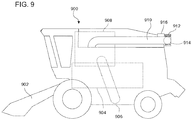
- FIG. 9 schematically illustrates an agricultural combine 900 that can be used in conjunction with a foldable auger assembly such as those described herein.
- the combine 900 generally comprises a wheel- or track-driven vehicle having a header 902 to cut and draw in crops, an internal threshing and separating system 904 to separate grain from other material, and a grain elevator 906 to lift the separated grain to a grain hopper 908.
- a first auger assembly 910 is attached to the remainder of the combine 900 at a first end that is in communication with the grain hopper 908.
- the first auger assembly 910 may be operatively connected to the grain hopper 908 by, for example, a grain extraction auger that extends from the bottom of the hopper to the first auger assembly. Alternatively, the first end of the first auger assembly may be positioned within the grain hopper 908 to directly extract grain therefrom.
- the second end of the first auger assembly 910 is attached via a linkage 912 to a second auger assembly 914.
Landscapes
- Engineering & Computer Science (AREA)
- Mechanical Engineering (AREA)
- Life Sciences & Earth Sciences (AREA)
- Environmental Sciences (AREA)
- Threshing Machine Elements (AREA)
Applications Claiming Priority (1)
| Application Number | Priority Date | Filing Date | Title |
|---|---|---|---|
| US16/175,062 US11019767B2 (en) | 2018-10-30 | 2018-10-30 | Folding auger coupling mechanism |
Publications (2)
| Publication Number | Publication Date |
|---|---|
| EP3649845A1 true EP3649845A1 (fr) | 2020-05-13 |
| EP3649845B1 EP3649845B1 (fr) | 2021-06-23 |
Family
ID=68424691
Family Applications (1)
| Application Number | Title | Priority Date | Filing Date |
|---|---|---|---|
| EP19206329.5A Active EP3649845B1 (fr) | 2018-10-30 | 2019-10-30 | Mécanisme rabattable de couplage de vis sans fin |
Country Status (3)
| Country | Link |
|---|---|
| US (1) | US11019767B2 (fr) |
| EP (1) | EP3649845B1 (fr) |
| CN (1) | CN111115131B (fr) |
Cited By (1)
| Publication number | Priority date | Publication date | Assignee | Title |
|---|---|---|---|---|
| EP4119395A1 (fr) * | 2021-07-15 | 2023-01-18 | CNH Industrial Belgium NV | Vis sans fin de remontée pour moissonneuse-batteuse |
Families Citing this family (6)
| Publication number | Priority date | Publication date | Assignee | Title |
|---|---|---|---|---|
| US11140829B2 (en) * | 2018-09-11 | 2021-10-12 | Unverferth Manufacturing Co., Inc. | Farm implement with folding auger |
| GB201900681D0 (en) * | 2019-01-17 | 2019-03-06 | Agco Do Brasil Sa Ltda | Combine harvester tailings return system |
| CN111719863A (zh) * | 2020-07-27 | 2020-09-29 | 常德市俊德科技发展有限公司 | 一种混凝土用泵送系统及其输送方法 |
| US12428223B2 (en) | 2021-07-06 | 2025-09-30 | The Heil Co. | Refuse packer system with auger |
| US12369527B2 (en) | 2021-09-09 | 2025-07-29 | Cnh Industrial America Llc | Bubble up auger for combine harvester |
| JP2023110352A (ja) * | 2022-01-28 | 2023-08-09 | 三菱マヒンドラ農機株式会社 | 粉粒体の搬送装置 |
Citations (8)
| Publication number | Priority date | Publication date | Assignee | Title |
|---|---|---|---|---|
| US3664444A (en) * | 1970-05-11 | 1972-05-23 | Mobile Drilling Co Inc | Air drilling method using controlled split stream |
| US4669945A (en) * | 1986-03-26 | 1987-06-02 | J. I. Case Company | Foldable and swivelable hopper-loading screw conveyor |
| US5100281A (en) * | 1989-07-26 | 1992-03-31 | J. & M. Manufacturing Co., Inc. | Grain wagon with unload mechanism |
| US5673543A (en) * | 1996-01-04 | 1997-10-07 | Byron Enterprises, Inc | Foldable corn head with unobstructed auger |
| US7168554B2 (en) | 2003-07-17 | 2007-01-30 | Pitonyak Machinery Corporation | Grain cart and auger construction |
| US7367881B2 (en) | 2006-02-10 | 2008-05-06 | Agco Corporation | High capacity combine grain bin unload system |
| US8033377B2 (en) | 2005-11-10 | 2011-10-11 | Deere & Company | Folding unloading auger engagement assistors |
| US8827782B2 (en) | 2012-08-31 | 2014-09-09 | Cnh Industrial America Llc | Auger drive coupler assembly having a friction clutch for a combine harvester |
Family Cites Families (16)
| Publication number | Priority date | Publication date | Assignee | Title |
|---|---|---|---|---|
| US2772767A (en) * | 1954-01-08 | 1956-12-04 | Hotchkiss Steel Products Co | Vehicle mounted load discharging elevator |
| US3337068A (en) * | 1967-01-11 | 1967-08-22 | James L Meharry | Gravity bed auger arrangement |
| US3638816A (en) * | 1970-03-30 | 1972-02-01 | Sperry Rand Corp | Hinged unloading auger for grinder-mixer |
| US4368003A (en) * | 1980-11-28 | 1983-01-11 | Macdonald John T | Foldable farm implement with single port hopper-feeding auger |
| US4440539A (en) * | 1982-02-01 | 1984-04-03 | Sullivan Thomas J | Method and apparatus for conveying particulate matter |
| US5013208A (en) * | 1989-07-26 | 1991-05-07 | J & M Manufacturing Co., Inc. | Grain wagon with unload mechanism |
| AU1689597A (en) * | 1996-01-04 | 1997-08-01 | Byron Enterprises, Inc. | Foldable corn head with unobstructed auger |
| US5724798A (en) * | 1996-07-08 | 1998-03-10 | Byron Enterprises Inc. | Latch for a folding corn head |
| US6422376B1 (en) * | 2000-10-11 | 2002-07-23 | Sunflower Manufacturing Company, Inc. | Auger coupler |
| US9723783B2 (en) * | 2012-05-29 | 2017-08-08 | Cnh Industrial America Llc | Folding auger assembly coupler |
| US9410304B2 (en) * | 2014-04-28 | 2016-08-09 | Cnh Industrial America Llc | Lift assembly for a work vehicle |
| US9556897B2 (en) * | 2015-04-30 | 2017-01-31 | Cnh Industrial America Llc | Driven shaft with rotational kinetic energy dissipation for an agricultural harvester |
| US10399787B2 (en) * | 2016-03-15 | 2019-09-03 | Deere & Company | Conveyor and conveyor drive for filling a combine grain tank |
| CN105775775B (zh) * | 2016-04-25 | 2017-11-17 | 武汉开锐海洋起重技术有限公司 | 流动式多用途散货螺旋堆装机 |
| CN206108212U (zh) * | 2016-10-19 | 2017-04-19 | 杭州岭轩科技有限公司 | 一种手提式智能灌注机 |
| CN107892187B (zh) * | 2017-11-14 | 2019-11-01 | 山东耀华特耐科技有限公司 | 一种抗凝固型耐火浇注料的快速输送设备 |
-
2018
- 2018-10-30 US US16/175,062 patent/US11019767B2/en active Active
-
2019
- 2019-10-30 CN CN201911040784.XA patent/CN111115131B/zh active Active
- 2019-10-30 EP EP19206329.5A patent/EP3649845B1/fr active Active
Patent Citations (10)
| Publication number | Priority date | Publication date | Assignee | Title |
|---|---|---|---|---|
| US3664444A (en) * | 1970-05-11 | 1972-05-23 | Mobile Drilling Co Inc | Air drilling method using controlled split stream |
| US4669945A (en) * | 1986-03-26 | 1987-06-02 | J. I. Case Company | Foldable and swivelable hopper-loading screw conveyor |
| US5100281A (en) * | 1989-07-26 | 1992-03-31 | J. & M. Manufacturing Co., Inc. | Grain wagon with unload mechanism |
| US5673543A (en) * | 1996-01-04 | 1997-10-07 | Byron Enterprises, Inc | Foldable corn head with unobstructed auger |
| US7168554B2 (en) | 2003-07-17 | 2007-01-30 | Pitonyak Machinery Corporation | Grain cart and auger construction |
| US7287639B2 (en) | 2003-07-17 | 2007-10-30 | Pitonyak Machinery Corporation | Grain cart and auger construction |
| US8033377B2 (en) | 2005-11-10 | 2011-10-11 | Deere & Company | Folding unloading auger engagement assistors |
| US7367881B2 (en) | 2006-02-10 | 2008-05-06 | Agco Corporation | High capacity combine grain bin unload system |
| US7494409B2 (en) | 2006-02-10 | 2009-02-24 | Agco Corporation | Foldable unloading auger assembly for the grain bin of a combine harvester |
| US8827782B2 (en) | 2012-08-31 | 2014-09-09 | Cnh Industrial America Llc | Auger drive coupler assembly having a friction clutch for a combine harvester |
Cited By (2)
| Publication number | Priority date | Publication date | Assignee | Title |
|---|---|---|---|---|
| EP4119395A1 (fr) * | 2021-07-15 | 2023-01-18 | CNH Industrial Belgium NV | Vis sans fin de remontée pour moissonneuse-batteuse |
| US12120984B2 (en) | 2021-07-15 | 2024-10-22 | Cnh Industrial America Llc | Bubble up auger for combine harvester |
Also Published As
| Publication number | Publication date |
|---|---|
| EP3649845B1 (fr) | 2021-06-23 |
| US20200128736A1 (en) | 2020-04-30 |
| CN111115131B (zh) | 2022-03-25 |
| CN111115131A (zh) | 2020-05-08 |
| BR102019022681A2 (pt) | 2020-06-02 |
| US11019767B2 (en) | 2021-06-01 |
Similar Documents
| Publication | Publication Date | Title |
|---|---|---|
| EP3649845B1 (fr) | Mécanisme rabattable de couplage de vis sans fin | |
| US11708862B2 (en) | Clutch arrangement for a roadable aircraft | |
| KR102364749B1 (ko) | 굴착 장치 및 굴착 장치의 굴착 헤드 | |
| EP1955947A2 (fr) | Actionneur | |
| CN102462522A (zh) | 用于动力手术装置的配接组件 | |
| EP0720692B1 (fr) | Pompe peristaltique a desaccouplement rapide de la tete de rotor | |
| US10746231B2 (en) | Connect-disconnect apparatus for a vehicle drivetrain | |
| US4932809A (en) | Lost motion splined coupling device | |
| US11639208B2 (en) | Final drive disconnect mechanism via transmission | |
| US4057327A (en) | Drive apparatus for an optical system | |
| US7704022B2 (en) | Motorized precision spindle apparatus | |
| EP2005557B1 (fr) | Moteur de broche | |
| KR20210064277A (ko) | 면도 장치를 위한 개선된 모발-절삭 유닛 | |
| RU2665620C2 (ru) | Двухсторонний выдвигаемый приводной вал для автоматического присоединения жатки | |
| WO2018161484A1 (fr) | Dispositif de transmission universel flexible | |
| EP0952027B1 (fr) | Prise de force pour véhicule agricole et procédé de mise en oeuvre associé | |
| BR102019022681B1 (pt) | Trado dobrável e colheitadeira agrícola | |
| JP2023533440A (ja) | 反転型ボールねじアクチュエータ | |
| US4569427A (en) | Shaft coupling device | |
| WO2022159907A1 (fr) | Treuil ayant un embrayage antiretour bidirectionnel et/ou un coupleur de couple et coupleur de couple pour un treuil | |
| CN217336409U (zh) | 一种可伸缩的侧置传动装置和条播机 | |
| US20200018228A1 (en) | Rotary combustion engine rotor deactivation and method | |
| CN221120699U (zh) | 用于血管介入手术机器人的动力连接结构及手术机器人 | |
| KR102901876B1 (ko) | 디스커넥트 기능이 포함된 클러치 제어 장치 | |
| CN223388103U (zh) | 一种电动执行器的传动机构 |
Legal Events
| Date | Code | Title | Description |
|---|---|---|---|
| PUAI | Public reference made under article 153(3) epc to a published international application that has entered the european phase |
Free format text: ORIGINAL CODE: 0009012 |
|
| STAA | Information on the status of an ep patent application or granted ep patent |
Free format text: STATUS: THE APPLICATION HAS BEEN PUBLISHED |
|
| AK | Designated contracting states |
Kind code of ref document: A1 Designated state(s): AL AT BE BG CH CY CZ DE DK EE ES FI FR GB GR HR HU IE IS IT LI LT LU LV MC MK MT NL NO PL PT RO RS SE SI SK SM TR |
|
| AX | Request for extension of the european patent |
Extension state: BA ME |
|
| STAA | Information on the status of an ep patent application or granted ep patent |
Free format text: STATUS: REQUEST FOR EXAMINATION WAS MADE |
|
| 17P | Request for examination filed |
Effective date: 20201113 |
|
| RBV | Designated contracting states (corrected) |
Designated state(s): AL AT BE BG CH CY CZ DE DK EE ES FI FR GB GR HR HU IE IS IT LI LT LU LV MC MK MT NL NO PL PT RO RS SE SI SK SM TR |
|
| RIC1 | Information provided on ipc code assigned before grant |
Ipc: B65G 33/14 20060101ALN20201130BHEP Ipc: A01D 41/12 20060101ALI20201130BHEP Ipc: A01F 12/46 20060101AFI20201130BHEP Ipc: A01D 61/00 20060101ALN20201130BHEP Ipc: A01D 41/14 20060101ALN20201130BHEP Ipc: B65G 33/32 20060101ALI20201130BHEP |
|
| GRAP | Despatch of communication of intention to grant a patent |
Free format text: ORIGINAL CODE: EPIDOSNIGR1 |
|
| STAA | Information on the status of an ep patent application or granted ep patent |
Free format text: STATUS: GRANT OF PATENT IS INTENDED |
|
| INTG | Intention to grant announced |
Effective date: 20210114 |
|
| GRAS | Grant fee paid |
Free format text: ORIGINAL CODE: EPIDOSNIGR3 |
|
| GRAA | (expected) grant |
Free format text: ORIGINAL CODE: 0009210 |
|
| STAA | Information on the status of an ep patent application or granted ep patent |
Free format text: STATUS: THE PATENT HAS BEEN GRANTED |
|
| AK | Designated contracting states |
Kind code of ref document: B1 Designated state(s): AL AT BE BG CH CY CZ DE DK EE ES FI FR GB GR HR HU IE IS IT LI LT LU LV MC MK MT NL NO PL PT RO RS SE SI SK SM TR |
|
| REG | Reference to a national code |
Ref country code: GB Ref legal event code: FG4D |
|
| REG | Reference to a national code |
Ref country code: CH Ref legal event code: EP |
|
| REG | Reference to a national code |
Ref country code: DE Ref legal event code: R096 Ref document number: 602019005573 Country of ref document: DE Ref country code: AT Ref legal event code: REF Ref document number: 1403448 Country of ref document: AT Kind code of ref document: T Effective date: 20210715 |
|
| REG | Reference to a national code |
Ref country code: IE Ref legal event code: FG4D |
|
| REG | Reference to a national code |
Ref country code: LT Ref legal event code: MG9D |
|
| PG25 | Lapsed in a contracting state [announced via postgrant information from national office to epo] |
Ref country code: HR Free format text: LAPSE BECAUSE OF FAILURE TO SUBMIT A TRANSLATION OF THE DESCRIPTION OR TO PAY THE FEE WITHIN THE PRESCRIBED TIME-LIMIT Effective date: 20210623 Ref country code: LT Free format text: LAPSE BECAUSE OF FAILURE TO SUBMIT A TRANSLATION OF THE DESCRIPTION OR TO PAY THE FEE WITHIN THE PRESCRIBED TIME-LIMIT Effective date: 20210623 Ref country code: FI Free format text: LAPSE BECAUSE OF FAILURE TO SUBMIT A TRANSLATION OF THE DESCRIPTION OR TO PAY THE FEE WITHIN THE PRESCRIBED TIME-LIMIT Effective date: 20210623 Ref country code: BG Free format text: LAPSE BECAUSE OF FAILURE TO SUBMIT A TRANSLATION OF THE DESCRIPTION OR TO PAY THE FEE WITHIN THE PRESCRIBED TIME-LIMIT Effective date: 20210923 |
|
| REG | Reference to a national code |
Ref country code: AT Ref legal event code: MK05 Ref document number: 1403448 Country of ref document: AT Kind code of ref document: T Effective date: 20210623 |
|
| PG25 | Lapsed in a contracting state [announced via postgrant information from national office to epo] |
Ref country code: RS Free format text: LAPSE BECAUSE OF FAILURE TO SUBMIT A TRANSLATION OF THE DESCRIPTION OR TO PAY THE FEE WITHIN THE PRESCRIBED TIME-LIMIT Effective date: 20210623 Ref country code: SE Free format text: LAPSE BECAUSE OF FAILURE TO SUBMIT A TRANSLATION OF THE DESCRIPTION OR TO PAY THE FEE WITHIN THE PRESCRIBED TIME-LIMIT Effective date: 20210623 Ref country code: LV Free format text: LAPSE BECAUSE OF FAILURE TO SUBMIT A TRANSLATION OF THE DESCRIPTION OR TO PAY THE FEE WITHIN THE PRESCRIBED TIME-LIMIT Effective date: 20210623 Ref country code: NO Free format text: LAPSE BECAUSE OF FAILURE TO SUBMIT A TRANSLATION OF THE DESCRIPTION OR TO PAY THE FEE WITHIN THE PRESCRIBED TIME-LIMIT Effective date: 20210923 Ref country code: GR Free format text: LAPSE BECAUSE OF FAILURE TO SUBMIT A TRANSLATION OF THE DESCRIPTION OR TO PAY THE FEE WITHIN THE PRESCRIBED TIME-LIMIT Effective date: 20210924 |
|
| REG | Reference to a national code |
Ref country code: NL Ref legal event code: MP Effective date: 20210623 |
|
| PG25 | Lapsed in a contracting state [announced via postgrant information from national office to epo] |
Ref country code: CZ Free format text: LAPSE BECAUSE OF FAILURE TO SUBMIT A TRANSLATION OF THE DESCRIPTION OR TO PAY THE FEE WITHIN THE PRESCRIBED TIME-LIMIT Effective date: 20210623 Ref country code: AT Free format text: LAPSE BECAUSE OF FAILURE TO SUBMIT A TRANSLATION OF THE DESCRIPTION OR TO PAY THE FEE WITHIN THE PRESCRIBED TIME-LIMIT Effective date: 20210623 Ref country code: RO Free format text: LAPSE BECAUSE OF FAILURE TO SUBMIT A TRANSLATION OF THE DESCRIPTION OR TO PAY THE FEE WITHIN THE PRESCRIBED TIME-LIMIT Effective date: 20210623 Ref country code: NL Free format text: LAPSE BECAUSE OF FAILURE TO SUBMIT A TRANSLATION OF THE DESCRIPTION OR TO PAY THE FEE WITHIN THE PRESCRIBED TIME-LIMIT Effective date: 20210623 Ref country code: PT Free format text: LAPSE BECAUSE OF FAILURE TO SUBMIT A TRANSLATION OF THE DESCRIPTION OR TO PAY THE FEE WITHIN THE PRESCRIBED TIME-LIMIT Effective date: 20211025 Ref country code: SM Free format text: LAPSE BECAUSE OF FAILURE TO SUBMIT A TRANSLATION OF THE DESCRIPTION OR TO PAY THE FEE WITHIN THE PRESCRIBED TIME-LIMIT Effective date: 20210623 Ref country code: EE Free format text: LAPSE BECAUSE OF FAILURE TO SUBMIT A TRANSLATION OF THE DESCRIPTION OR TO PAY THE FEE WITHIN THE PRESCRIBED TIME-LIMIT Effective date: 20210623 Ref country code: ES Free format text: LAPSE BECAUSE OF FAILURE TO SUBMIT A TRANSLATION OF THE DESCRIPTION OR TO PAY THE FEE WITHIN THE PRESCRIBED TIME-LIMIT Effective date: 20210623 Ref country code: SK Free format text: LAPSE BECAUSE OF FAILURE TO SUBMIT A TRANSLATION OF THE DESCRIPTION OR TO PAY THE FEE WITHIN THE PRESCRIBED TIME-LIMIT Effective date: 20210623 |
|
| PG25 | Lapsed in a contracting state [announced via postgrant information from national office to epo] |
Ref country code: PL Free format text: LAPSE BECAUSE OF FAILURE TO SUBMIT A TRANSLATION OF THE DESCRIPTION OR TO PAY THE FEE WITHIN THE PRESCRIBED TIME-LIMIT Effective date: 20210623 |
|
| REG | Reference to a national code |
Ref country code: DE Ref legal event code: R097 Ref document number: 602019005573 Country of ref document: DE |
|
| PG25 | Lapsed in a contracting state [announced via postgrant information from national office to epo] |
Ref country code: DK Free format text: LAPSE BECAUSE OF FAILURE TO SUBMIT A TRANSLATION OF THE DESCRIPTION OR TO PAY THE FEE WITHIN THE PRESCRIBED TIME-LIMIT Effective date: 20210623 |
|
| PLBE | No opposition filed within time limit |
Free format text: ORIGINAL CODE: 0009261 |
|
| STAA | Information on the status of an ep patent application or granted ep patent |
Free format text: STATUS: NO OPPOSITION FILED WITHIN TIME LIMIT |
|
| 26N | No opposition filed |
Effective date: 20220324 |
|
| PG25 | Lapsed in a contracting state [announced via postgrant information from national office to epo] |
Ref country code: AL Free format text: LAPSE BECAUSE OF FAILURE TO SUBMIT A TRANSLATION OF THE DESCRIPTION OR TO PAY THE FEE WITHIN THE PRESCRIBED TIME-LIMIT Effective date: 20210623 |
|
| REG | Reference to a national code |
Ref country code: BE Ref legal event code: MM Effective date: 20211031 |
|
| PG25 | Lapsed in a contracting state [announced via postgrant information from national office to epo] |
Ref country code: MC Free format text: LAPSE BECAUSE OF FAILURE TO SUBMIT A TRANSLATION OF THE DESCRIPTION OR TO PAY THE FEE WITHIN THE PRESCRIBED TIME-LIMIT Effective date: 20210623 |
|
| PG25 | Lapsed in a contracting state [announced via postgrant information from national office to epo] |
Ref country code: LU Free format text: LAPSE BECAUSE OF NON-PAYMENT OF DUE FEES Effective date: 20211030 Ref country code: BE Free format text: LAPSE BECAUSE OF NON-PAYMENT OF DUE FEES Effective date: 20211031 |
|
| PG25 | Lapsed in a contracting state [announced via postgrant information from national office to epo] |
Ref country code: IE Free format text: LAPSE BECAUSE OF NON-PAYMENT OF DUE FEES Effective date: 20211030 |
|
| REG | Reference to a national code |
Ref country code: CH Ref legal event code: PL |
|
| PG25 | Lapsed in a contracting state [announced via postgrant information from national office to epo] |
Ref country code: CY Free format text: LAPSE BECAUSE OF FAILURE TO SUBMIT A TRANSLATION OF THE DESCRIPTION OR TO PAY THE FEE WITHIN THE PRESCRIBED TIME-LIMIT Effective date: 20210623 |
|
| PG25 | Lapsed in a contracting state [announced via postgrant information from national office to epo] |
Ref country code: LI Free format text: LAPSE BECAUSE OF NON-PAYMENT OF DUE FEES Effective date: 20221031 Ref country code: HU Free format text: LAPSE BECAUSE OF FAILURE TO SUBMIT A TRANSLATION OF THE DESCRIPTION OR TO PAY THE FEE WITHIN THE PRESCRIBED TIME-LIMIT; INVALID AB INITIO Effective date: 20191030 Ref country code: CH Free format text: LAPSE BECAUSE OF NON-PAYMENT OF DUE FEES Effective date: 20221031 |
|
| PG25 | Lapsed in a contracting state [announced via postgrant information from national office to epo] |
Ref country code: MK Free format text: LAPSE BECAUSE OF FAILURE TO SUBMIT A TRANSLATION OF THE DESCRIPTION OR TO PAY THE FEE WITHIN THE PRESCRIBED TIME-LIMIT Effective date: 20210623 |
|
| PG25 | Lapsed in a contracting state [announced via postgrant information from national office to epo] |
Ref country code: MT Free format text: LAPSE BECAUSE OF FAILURE TO SUBMIT A TRANSLATION OF THE DESCRIPTION OR TO PAY THE FEE WITHIN THE PRESCRIBED TIME-LIMIT Effective date: 20210623 |
|
| PGFP | Annual fee paid to national office [announced via postgrant information from national office to epo] |
Ref country code: IT Payment date: 20241022 Year of fee payment: 6 |
|
| PG25 | Lapsed in a contracting state [announced via postgrant information from national office to epo] |
Ref country code: TR Free format text: LAPSE BECAUSE OF FAILURE TO SUBMIT A TRANSLATION OF THE DESCRIPTION OR TO PAY THE FEE WITHIN THE PRESCRIBED TIME-LIMIT Effective date: 20210623 |
|
| PGFP | Annual fee paid to national office [announced via postgrant information from national office to epo] |
Ref country code: DE Payment date: 20251028 Year of fee payment: 7 |
|
| PGFP | Annual fee paid to national office [announced via postgrant information from national office to epo] |
Ref country code: GB Payment date: 20251021 Year of fee payment: 7 |
|
| PGFP | Annual fee paid to national office [announced via postgrant information from national office to epo] |
Ref country code: FR Payment date: 20251027 Year of fee payment: 7 |