EP3647828A1 - Abschirmstruktur und sicherheitsinspektionskanal einer sicherheitsinspektionsvorrichtung - Google Patents
Abschirmstruktur und sicherheitsinspektionskanal einer sicherheitsinspektionsvorrichtung Download PDFInfo
- Publication number
- EP3647828A1 EP3647828A1 EP19823761.2A EP19823761A EP3647828A1 EP 3647828 A1 EP3647828 A1 EP 3647828A1 EP 19823761 A EP19823761 A EP 19823761A EP 3647828 A1 EP3647828 A1 EP 3647828A1
- Authority
- EP
- European Patent Office
- Prior art keywords
- shielding
- carbon fiber
- channel
- layer
- safety inspection
- Prior art date
- Legal status (The legal status is an assumption and is not a legal conclusion. Google has not performed a legal analysis and makes no representation as to the accuracy of the status listed.)
- Granted
Links
Images


Classifications
-
- G—PHYSICS
- G01—MEASURING; TESTING
- G01V—GEOPHYSICS; GRAVITATIONAL MEASUREMENTS; DETECTING MASSES OR OBJECTS; TAGS
- G01V5/00—Prospecting or detecting by the use of ionising radiation, e.g. of natural or induced radioactivity
- G01V5/20—Detecting prohibited goods, e.g. weapons, explosives, hazardous substances, contraband or smuggled objects
- G01V5/22—Active interrogation, i.e. by irradiating objects or goods using external radiation sources, e.g. using gamma rays or cosmic rays
- G01V5/226—Active interrogation, i.e. by irradiating objects or goods using external radiation sources, e.g. using gamma rays or cosmic rays using tomography
-
- B—PERFORMING OPERATIONS; TRANSPORTING
- B32—LAYERED PRODUCTS
- B32B—LAYERED PRODUCTS, i.e. PRODUCTS BUILT-UP OF STRATA OF FLAT OR NON-FLAT, e.g. CELLULAR OR HONEYCOMB, FORM
- B32B3/00—Layered products comprising a layer with external or internal discontinuities or unevennesses, or a layer of non-planar shape; Layered products comprising a layer having particular features of form
- B32B3/02—Layered products comprising a layer with external or internal discontinuities or unevennesses, or a layer of non-planar shape; Layered products comprising a layer having particular features of form characterised by features of form at particular places, e.g. in edge regions
- B32B3/04—Layered products comprising a layer with external or internal discontinuities or unevennesses, or a layer of non-planar shape; Layered products comprising a layer having particular features of form characterised by features of form at particular places, e.g. in edge regions characterised by at least one layer folded at the edge, e.g. over another layer ; characterised by at least one layer enveloping or enclosing a material
-
- B—PERFORMING OPERATIONS; TRANSPORTING
- B32—LAYERED PRODUCTS
- B32B—LAYERED PRODUCTS, i.e. PRODUCTS BUILT-UP OF STRATA OF FLAT OR NON-FLAT, e.g. CELLULAR OR HONEYCOMB, FORM
- B32B5/00—Layered products characterised by the non- homogeneity or physical structure, i.e. comprising a fibrous, filamentary, particulate or foam layer; Layered products characterised by having a layer differing constitutionally or physically in different parts
- B32B5/22—Layered products characterised by the non- homogeneity or physical structure, i.e. comprising a fibrous, filamentary, particulate or foam layer; Layered products characterised by having a layer differing constitutionally or physically in different parts characterised by the presence of two or more layers which are next to each other and are fibrous, filamentary, formed of particles or foamed
- B32B5/24—Layered products characterised by the non- homogeneity or physical structure, i.e. comprising a fibrous, filamentary, particulate or foam layer; Layered products characterised by having a layer differing constitutionally or physically in different parts characterised by the presence of two or more layers which are next to each other and are fibrous, filamentary, formed of particles or foamed one layer being a fibrous or filamentary layer
- B32B5/26—Layered products characterised by the non- homogeneity or physical structure, i.e. comprising a fibrous, filamentary, particulate or foam layer; Layered products characterised by having a layer differing constitutionally or physically in different parts characterised by the presence of two or more layers which are next to each other and are fibrous, filamentary, formed of particles or foamed one layer being a fibrous or filamentary layer another layer next to it also being fibrous or filamentary
-
- B—PERFORMING OPERATIONS; TRANSPORTING
- B32—LAYERED PRODUCTS
- B32B—LAYERED PRODUCTS, i.e. PRODUCTS BUILT-UP OF STRATA OF FLAT OR NON-FLAT, e.g. CELLULAR OR HONEYCOMB, FORM
- B32B1/00—Layered products having a non-planar shape
- B32B1/08—Tubular products
-
- B—PERFORMING OPERATIONS; TRANSPORTING
- B32—LAYERED PRODUCTS
- B32B—LAYERED PRODUCTS, i.e. PRODUCTS BUILT-UP OF STRATA OF FLAT OR NON-FLAT, e.g. CELLULAR OR HONEYCOMB, FORM
- B32B2250/00—Layers arrangement
- B32B2250/40—Symmetrical or sandwich layers, e.g. ABA, ABCBA, ABCCBA
-
- B—PERFORMING OPERATIONS; TRANSPORTING
- B32—LAYERED PRODUCTS
- B32B—LAYERED PRODUCTS, i.e. PRODUCTS BUILT-UP OF STRATA OF FLAT OR NON-FLAT, e.g. CELLULAR OR HONEYCOMB, FORM
- B32B2255/00—Coating on the layer surface
- B32B2255/02—Coating on the layer surface on fibrous or filamentary layer
-
- B—PERFORMING OPERATIONS; TRANSPORTING
- B32—LAYERED PRODUCTS
- B32B—LAYERED PRODUCTS, i.e. PRODUCTS BUILT-UP OF STRATA OF FLAT OR NON-FLAT, e.g. CELLULAR OR HONEYCOMB, FORM
- B32B2255/00—Coating on the layer surface
- B32B2255/26—Polymeric coating
-
- B—PERFORMING OPERATIONS; TRANSPORTING
- B32—LAYERED PRODUCTS
- B32B—LAYERED PRODUCTS, i.e. PRODUCTS BUILT-UP OF STRATA OF FLAT OR NON-FLAT, e.g. CELLULAR OR HONEYCOMB, FORM
- B32B2262/00—Composition or structural features of fibres which form a fibrous or filamentary layer or are present as additives
- B32B2262/02—Synthetic macromolecular fibres
- B32B2262/0261—Polyamide fibres
- B32B2262/0269—Aromatic polyamide fibres
-
- B—PERFORMING OPERATIONS; TRANSPORTING
- B32—LAYERED PRODUCTS
- B32B—LAYERED PRODUCTS, i.e. PRODUCTS BUILT-UP OF STRATA OF FLAT OR NON-FLAT, e.g. CELLULAR OR HONEYCOMB, FORM
- B32B2262/00—Composition or structural features of fibres which form a fibrous or filamentary layer or are present as additives
- B32B2262/10—Inorganic fibres
- B32B2262/106—Carbon fibres, e.g. graphite fibres
-
- B—PERFORMING OPERATIONS; TRANSPORTING
- B32—LAYERED PRODUCTS
- B32B—LAYERED PRODUCTS, i.e. PRODUCTS BUILT-UP OF STRATA OF FLAT OR NON-FLAT, e.g. CELLULAR OR HONEYCOMB, FORM
- B32B2307/00—Properties of the layers or laminate
- B32B2307/40—Properties of the layers or laminate having particular optical properties
-
- B—PERFORMING OPERATIONS; TRANSPORTING
- B32—LAYERED PRODUCTS
- B32B—LAYERED PRODUCTS, i.e. PRODUCTS BUILT-UP OF STRATA OF FLAT OR NON-FLAT, e.g. CELLULAR OR HONEYCOMB, FORM
- B32B2307/00—Properties of the layers or laminate
- B32B2307/50—Properties of the layers or laminate having particular mechanical properties
- B32B2307/536—Hardness
-
- B—PERFORMING OPERATIONS; TRANSPORTING
- B32—LAYERED PRODUCTS
- B32B—LAYERED PRODUCTS, i.e. PRODUCTS BUILT-UP OF STRATA OF FLAT OR NON-FLAT, e.g. CELLULAR OR HONEYCOMB, FORM
- B32B2307/00—Properties of the layers or laminate
- B32B2307/50—Properties of the layers or laminate having particular mechanical properties
- B32B2307/554—Wear resistance
-
- B—PERFORMING OPERATIONS; TRANSPORTING
- B32—LAYERED PRODUCTS
- B32B—LAYERED PRODUCTS, i.e. PRODUCTS BUILT-UP OF STRATA OF FLAT OR NON-FLAT, e.g. CELLULAR OR HONEYCOMB, FORM
- B32B2307/00—Properties of the layers or laminate
- B32B2307/70—Other properties
- B32B2307/732—Dimensional properties
-
- B—PERFORMING OPERATIONS; TRANSPORTING
- B32—LAYERED PRODUCTS
- B32B—LAYERED PRODUCTS, i.e. PRODUCTS BUILT-UP OF STRATA OF FLAT OR NON-FLAT, e.g. CELLULAR OR HONEYCOMB, FORM
- B32B2433/00—Closed loop articles
- B32B2433/02—Conveyor belts
-
- B—PERFORMING OPERATIONS; TRANSPORTING
- B32—LAYERED PRODUCTS
- B32B—LAYERED PRODUCTS, i.e. PRODUCTS BUILT-UP OF STRATA OF FLAT OR NON-FLAT, e.g. CELLULAR OR HONEYCOMB, FORM
- B32B25/00—Layered products comprising a layer of natural or synthetic rubber
- B32B25/02—Layered products comprising a layer of natural or synthetic rubber with fibres or particles being present as additives in the layer
-
- B—PERFORMING OPERATIONS; TRANSPORTING
- B32—LAYERED PRODUCTS
- B32B—LAYERED PRODUCTS, i.e. PRODUCTS BUILT-UP OF STRATA OF FLAT OR NON-FLAT, e.g. CELLULAR OR HONEYCOMB, FORM
- B32B2571/00—Protective equipment
-
- B—PERFORMING OPERATIONS; TRANSPORTING
- B32—LAYERED PRODUCTS
- B32B—LAYERED PRODUCTS, i.e. PRODUCTS BUILT-UP OF STRATA OF FLAT OR NON-FLAT, e.g. CELLULAR OR HONEYCOMB, FORM
- B32B27/00—Layered products comprising a layer of synthetic resin
- B32B27/12—Layered products comprising a layer of synthetic resin next to a fibrous or filamentary layer
-
- B—PERFORMING OPERATIONS; TRANSPORTING
- B32—LAYERED PRODUCTS
- B32B—LAYERED PRODUCTS, i.e. PRODUCTS BUILT-UP OF STRATA OF FLAT OR NON-FLAT, e.g. CELLULAR OR HONEYCOMB, FORM
- B32B27/00—Layered products comprising a layer of synthetic resin
- B32B27/40—Layered products comprising a layer of synthetic resin comprising polyurethanes
Definitions
- the present disclosure relates to fields of safety inspection equipment, in particular to a shielding structure of safety inspection equipment and a safety inspection channel.
- a channel carbon fiber shielding structure of a CT imaging system of major security inspection equipment is formed by carbon fiber layers.
- the carbon fiber layer can be configured to be a single-layer, double-layer and multi-layer.
- the single-layer carbon fiber shielding structure (i.e., including a single-layer carbon fiber layer) has a thickness of about 0.2-0.3 mm, with an advantage of having little influence on imaging quality. But the single-layer carbon fiber shielding structure has poor rigidity to easily collapse when luggage passes through it, and has a poor wear resistance.
- the double-layer carbon fiber shielding structure (i.e., including two layers of the carbon fiber layers) has a thickness of about 0.5mm, with an advantage of having less influence on the imaging quality and better rigidity than the single-layer carbon fiber shielding structure. But the double-layer carbon fiber shielding structure has a rigidity not to satisfy occasions with a wider beam surface, and has a poor wear resistance.
- the multi-layer carbon fiber shielding structure (i.e., including more than two layers of the carbon fiber layers) has different thicknesses according to different layers of the carbon fiber.
- the influence on the imaging quality is greater to cause the imaging quality poorer and the wear resistance bad.
- cost of the carbon fiber is calculated based on per square meter of the single-layer, so that as the number of carbon fiber layers increases, the cost can be multiply increased.
- the thinner the carbon fiber shielding plate the better the impact on the imaging quality.
- the carbon fiber shielding plate is better to be thicker.
- the shielding structure and the channel structure of major security inspection equipment are installed by pressing plates, and there are steps between the pressing plate and the shielding layer, on which dust or sundries are easy to be accumulated, and thus affecting imaging.
- the present disclosure provides a shielding structure of a safety inspection equipment and a safety inspection channel, which can improve rigidity of the shielding structure while reducing influence on imaging quality.
- the present disclosure provides a shielding structure of the safety inspection equipment, including a first carbon fiber layer, a polyurethane layer and a second carbon fiber layer sequentially, which are stacked to be configured as a shielding channel with two opened ends; the second carbon fiber layer is an outer layer of the shielding channel; the first carbon fiber layer and the second carbon fiber layer are made of carbon fiber materials; and the polyurethane layer is made of polyurethane materials.
- a safety inspection channel of a safety inspection equipment is further provided.
- the safety inspection channel includes a channel structure and the aforesaid shielding structure, wherein the channel structure is respectively connected and communicated with both ends of the shielding channel to form a through safety inspection channel.
- the present disclosure has the following advantages: in the present disclosure, the polyurethane board layer is added between the two carbon fiber layers, since the carbon fiber layer has good strength, the carbon fiber layers are covered on the both sides of the polyurethane board to ensure the overall strength, so that the rigidity of the shielding structure can be improved. And the rigidity of the shielding structure has little influence on the imaging quality, so that the rigidity of the shielding structure can be improved while reducing the influence on the imaging quality.
- the polyurethane board layer has small density, so that the polyurethane board layer is lighter than the carbon fiber layer, and thus the total weight can be reduced. And, cost of the polyurethane board layer is low, thus reducing the overall cost.
- an outer layer of the shielding channel is a carbon fiber layer, for maintaining the strength of the shielding structure.
- the polyurethane layer is wrapped by the two carbon fiber layers, so that slag and debris of the polyurethane layer 20 can be avoided.
- the present disclosure can improve the multi-layer carbon fiber shielding plate structure, reduce the influence on the imaging quality, reduce the cost, and can improve the rigidity of the single-layer and double-layer carbon fiber shielding plate structures.
- FIG. 1 is a schematic cross-sectional view of a shielding structure in the related arts
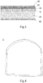
- FIG. 2 is a schematic cross-sectional view of a connecting portion of a safety inspection channel in the related arts.
- the shielding structure 1 is composed of two carbon fiber layers 100 and one rubber coating layer 200, each layer of which has a thickness of about 0.2mm, totally having the thickness of about 0.6mm. This shielding structure is thinner and has less influence on the imaging quality, but for occasions with wider beam surface, the shielding structure has un-satisfied rigidity and poor wear resistance.
- the shielding structure 1 has the uniform thickness, when the shielding structure 1 is connected with the adjacent channel structure 2, a pressing plate 3 and a supporting plate 4 are respectively arranged on inner and outer surfaces of the shielding structure 1, so that a step 5 is formed between the pressing plate 3 and the surface of the shielding structure 1. Dust or sundries are easily accumulated at the step 5, and thereby affecting imaging.
- the present disclosure provides the shielding structure 1 of a safety inspection equipment.
- the shielding structure 1 and the channel structure 2 form a safety inspection channel 1000.
- the shielding structure 1 is used for forming a shielding channel 1', and the channel structures 2 are respectively connected and communicated with both ends of the shielding channel 1', so as to form a through safety inspection channel 1000.
- the safety inspection channel 1000 is mainly used in the safety inspection equipment of luggage.
- the safety inspection equipment is mainly used in occasions where safety inspection requirements for luggage are required.
- the shielding structure In the CT imaging system of the safety inspection equipment, the shielding structure has a simple structure, little influence on the imaging quality, light weight, durability and reliability, which are the key elements to affect the equipment imaging system. As shown in FIG.
- the shielding structure 1 of the safety inspection equipment of the present disclosure includes a first carbon fiber layer 10, a polyurethane layer 20 and a second carbon fiber layer 30 sequentially stacked, to form a shielding channel 1' with both ends opened. Since the shielding structure 1 of the present disclosure is used for the safety inspection equipment, the shielding structure 1 is wholly constructed as a channel structure to cooperatively form a safety inspection channel 1000.
- the second carbon fiber layer 30 is an outer layer of the shielding channel 1'.
- the first carbon fiber layer 10 and the second carbon fiber layer 30 are made of carbon fiber materials, and the polyurethane layer 20 is made of polyurethane materials.
- a polyurethane board layer (i.e., a polyurethane layer) is added between the two carbon fiber layers, since the carbon fiber layer has good strength, the carbon fiber layers are covered on the both sides of the polyurethane board to ensure the overall strength, so that the rigidity of the shielding structure can be improved. And the rigidity of the shielding structure has little influence on the imaging quality, so that the rigidity of the shielding structure can be improved while reducing the influence on the imaging quality.
- the polyurethane board layer has small density, so that the polyurethane board layer is lighter than the carbon fiber layer, and thus the total weight can be reduced. And, cost of the polyurethane board layer is low, thus reducing the overall cost.
- an outer layer of the shielding channel 1' is a carbon fiber layer, for maintaining the strength of the shielding structure 1.
- the polyurethane layer 20 is wrapped by the two carbon fiber layers, so that slag and debris of the polyurethane layer 20 can be avoided. Accordingly, compared with the existing carbon fiber shielding plate structure, the present disclosure can improve the multi-layer carbon fiber shielding plate structure, reduce the influence on the imaging quality, reduce the cost, and can improve the rigidity of the single-layer and double-layer carbon fiber shielding plate structures.
- the shielding structure 1 may further include a third carbon fiber layer 40, which is stacked on one side of the first carbon fiber layer 10 away from the polyurethane layer 20. Wherein, there is one or more third carbon fiber layers 40.
- the strength of the shielding structure 1 can be improved, and thus an impact resistance of the shielding structure 1 can be improved.
- the number of the third carbon fiber layers 40 can be determined according to requirement for the strength in different occasions.
- one third carbon fiber layer 40 is provided.
- more than one third carbon fiber layers 40 are provided, and are continuously stacked on one side of the first carbon fiber layer 10 away from the polyurethane layer 20.
- the shielding structure 1 may further include an aramid fiber layer 50, which is stacked on one side of the third carbon fiber layer 40 away from the first carbon fiber layer 10.
- the aramid fiber layer 50 has a good abrasion resistance for improving the abrasion resistance of an inner surface of the shielding structure 1, and the aramid fiber layer 50 has little influence on CT imaging.
- the shielding structure 1 may further include a rubber coating layer 60, which is stacked on one side of the aramid fiber layer 50 away from the third carbon fiber layer 40.
- the side of the rubber coating layer 60 away from the aramid fiber layer 50 which is used as a working surface for the surface of the product, has functions of decoration, weather resistance, crack prevention and the like, and plays a role of protection and decoration for a reinforcing layer, wherein the rubber coating layer 60 can be an improved resin.
- Each of the first carbon fiber layer 10, the second carbon fiber layer 30 and the third carbon fiber layer 40 has a thickness of 0.2 to 0.4 mm
- the polyurethane layer 20 has a thickness of 3 to 6 mm
- the aramid fiber layer 50 has a thickness of 0.3 to 0.5 mm.
- the thickness of the rubber coating layer 60 is 0.2mm
- the thickness of the aramid fiber layer 50 is 0.3mm
- the thicknesses of each of the first carbon fiber layer 10, the second carbon fiber layer 30 and the third carbon fiber layer 40 is 0.2mm
- the thickness of the polyurethane layer 20 is 5mm
- the total thickness of the shielding structure 1, that is, a sum of the thicknesses of the all layers is about 6mm. It should be understood that the thickness range is not limited thereto, and different values of the thickness can be selected according to different layers in different application occasions.
- the shielding channel 1' is of a three-block structure, which has three joints respectively located at two side walls and a bottom of the shielding channel 1'. And the three-block structure has stable support and high strength.
- the shielding channel 1' is of a two-half structure, which has two joints respectively located at the top and bottom portions of the shielding channel 1'. And the two-half structure is simple and easy to be assembled.
- the shielding passage 1' includes a shielding body 11 and two extending portions 12 connected with both opposite ends of the shielding body.
- Each of the extending portion 12 is connected with a portion between the outer surface and the inner surface of the shielding body 11 on both ends of the shielding body 11.
- the extending portion 12 extends along an axis x (the axis in this embodiment is an axis x in an extending direction of a safety inspection channel 1000, i.e., the axis x is parallel to a longitudinal direction of the safety inspection channel 1000 in FIG. 5 ).
- the thickness of the extending portion 12 is smaller than the thickness of the shielding body 11, and the extending portion 12 is disposed between the outer surface and the inner surface of the shielding body 11.
- the safety inspection channel 1000 further includes a pressing plate 3 and a supporting plate 4.
- the pressing plate 3 is pressed on the outer surface of the extending portion 12 and closely adjacent to the shielding body 11 and the channel structure 2.
- the outer surface of the pressing plate 3 is flush with the outer surfaces of the shielding body 11 and the channel structure 2.
- the supporting plate 4 is arranged on the inner surfaces of the extending portion 12 and the channel structure 2, and is flush with the inner surfaces of the extending portion 12 and the channel structure 2.
- the extending portion 12 is formed by extending an edge of the shielding body 11 (the extending portion 12 is formed continuously along the outer periphery of both ends of the shielding body 11).
- the extending portion 12 is structurally different from the shielding body 11 in that the structure of the shielding body 11 is identical to the structure of the aforesaid shielding structure 1, and the polyurethane layer is not contained in the extending portion 12. That is to say, the extending portion 12 is formed by pressing an extending portion of the fiber layer (which may also include a rubber coating layer) of the shielding body 11.
- the extending portion 12 is configured to reduce the thickness of the edge of the shielding structure 1, and furthermore, the extending portion 12 can be provided between the pressing plate 3 and the supporting plate 4, so that the shielding structure 1 can be installed in the safety inspection channel 1000. As shown in FIG. 7 , by optimizing the shielding structure 1, the outer surfaces of the shielding structure 1, the pressing plate 3, and the channel structure 2 are flush, to avoid steps at a junction of the pressing plate 3 and the shielding structure 1, and to avoid accumulating dusts or sundries at the steps.
- a polyurethane board layer is added between the two carbon fiber layers in the present disclosure, since the carbon fiber layer has good strength, the carbon fiber layers are covered on the both sides of the polyurethane board to ensure the overall strength, so that the rigidity of the shielding structure can be improved. And the rigidity of the shielding structure has little influence on the imaging quality, so that the rigidity of the shielding structure can be improved while reducing the influence on the imaging quality.
- the polyurethane board layer has small density, so that the polyurethane board layer is lighter than the carbon fiber layer, and thus the total weight can be reduced. And, cost of the polyurethane board layer is low, thus reducing the overall cost.
- the outer layer of the shielding channel 1' is a carbon fiber layer, for maintaining the strength of the shielding structure 1.
- the polyurethane layer 20 is wrapped by the two carbon fiber layers 10 and 30, so that the slag and debris of the polyurethane layer 20 can be avoided. Accordingly, compared with the existing carbon fiber shielding plate structure, the present disclosure can improve the multi-layer carbon fiber shielding plate structure, reduce the influence on the imaging quality, reduce the cost, and can improve the rigidity of the single-layer and double-layer carbon fiber shielding plate structures.
Landscapes
- Physics & Mathematics (AREA)
- High Energy & Nuclear Physics (AREA)
- Life Sciences & Earth Sciences (AREA)
- General Life Sciences & Earth Sciences (AREA)
- General Physics & Mathematics (AREA)
- Geophysics (AREA)
- Engineering & Computer Science (AREA)
- Mechanical Engineering (AREA)
- Aiming, Guidance, Guns With A Light Source, Armor, Camouflage, And Targets (AREA)
- Laminated Bodies (AREA)
- General Health & Medical Sciences (AREA)
- Nuclear Medicine, Radiotherapy & Molecular Imaging (AREA)
- Radiology & Medical Imaging (AREA)
- Health & Medical Sciences (AREA)
- Geophysics And Detection Of Objects (AREA)
- Filling Or Discharging Of Gas Storage Vessels (AREA)
- Investigating Materials By The Use Of Optical Means Adapted For Particular Applications (AREA)
- Testing Of Devices, Machine Parts, Or Other Structures Thereof (AREA)
- Analysing Materials By The Use Of Radiation (AREA)
Applications Claiming Priority (2)
| Application Number | Priority Date | Filing Date | Title |
|---|---|---|---|
| CN201810761941.5A CN108614303B (zh) | 2018-07-12 | 2018-07-12 | 安全检查通道 |
| PCT/CN2019/089048 WO2020010953A1 (zh) | 2018-07-12 | 2019-05-29 | 安全检查设备的屏蔽结构及安全检查通道 |
Publications (3)
| Publication Number | Publication Date |
|---|---|
| EP3647828A1 true EP3647828A1 (de) | 2020-05-06 |
| EP3647828A4 EP3647828A4 (de) | 2021-04-21 |
| EP3647828B1 EP3647828B1 (de) | 2025-07-09 |
Family
ID=63666384
Family Applications (1)
| Application Number | Title | Priority Date | Filing Date |
|---|---|---|---|
| EP19823761.2A Active EP3647828B1 (de) | 2018-07-12 | 2019-05-29 | Abschirmstruktur und sicherheitsinspektionskanal einer sicherheitsinspektionsvorrichtung |
Country Status (8)
| Country | Link |
|---|---|
| US (1) | US11385377B2 (de) |
| EP (1) | EP3647828B1 (de) |
| JP (1) | JP6976359B2 (de) |
| CN (1) | CN108614303B (de) |
| AU (2) | AU2019299864B2 (de) |
| CA (1) | CA3066392C (de) |
| MY (1) | MY199506A (de) |
| WO (1) | WO2020010953A1 (de) |
Cited By (1)
| Publication number | Priority date | Publication date | Assignee | Title |
|---|---|---|---|---|
| EP4159135A4 (de) * | 2020-05-29 | 2024-07-03 | Tsinghua University | Detektionsdurchgang, durchgangsanordnung und ct-detektionsvorrichtung |
Families Citing this family (2)
| Publication number | Priority date | Publication date | Assignee | Title |
|---|---|---|---|---|
| CN108614303B (zh) * | 2018-07-12 | 2024-10-01 | 同方威视技术股份有限公司 | 安全检查通道 |
| CN116773557B (zh) * | 2022-12-28 | 2024-02-13 | 清华大学 | 用于ct检测的检测通道及ct检测装置 |
Family Cites Families (27)
| Publication number | Priority date | Publication date | Assignee | Title |
|---|---|---|---|---|
| US3737661A (en) * | 1971-03-03 | 1973-06-05 | R Applegate | Portable x-ray radiation shielding device |
| CA985433A (en) * | 1973-07-20 | 1976-03-09 | Melvin L. Foster | High strength low attenuation couch top |
| FR2527920A1 (fr) * | 1982-06-04 | 1983-12-09 | Thomson Csf | Materiau composite pour accessoire d'appareil de radiologie |
| JPS6082296U (ja) * | 1983-11-11 | 1985-06-07 | 石川島播磨重工業株式会社 | 放射線遮蔽シ−ト |
| JPS62152839A (ja) * | 1985-12-27 | 1987-07-07 | 積水化学工業株式会社 | 繊維強化樹脂成形品 |
| JPH0651095A (ja) * | 1992-07-28 | 1994-02-25 | Sumitomo Metal Ind Ltd | 放射線遮蔽機能を有する防弾用材料 |
| US7476889B2 (en) * | 1998-12-07 | 2009-01-13 | Meridian Research And Development | Radiation detectable and protective articles |
| GB0525593D0 (en) * | 2005-12-16 | 2006-01-25 | Cxr Ltd | X-ray tomography inspection systems |
| US7484253B1 (en) * | 2003-05-27 | 2009-02-03 | Qfix Systems, Llc | Patient support element for radiation therapy that reduces skin radiation burn |
| US7991115B2 (en) * | 2007-12-12 | 2011-08-02 | Kabushiki Kaisha Toshiba | Medical image diagnostic device |
| CN102596043A (zh) * | 2009-06-08 | 2012-07-18 | 昂科罗格医疗公司 | 用于放射治疗的台面 |
| DE102009037565A1 (de) * | 2009-08-14 | 2011-02-24 | Mavig Gmbh | Beschichtete Mikrofaserbahn und Verfahren zur Herstellung derselben |
| JP2012093264A (ja) * | 2010-10-27 | 2012-05-17 | Nikkiso Co Ltd | 放射線遮蔽カバー |
| JP6058883B2 (ja) * | 2011-11-14 | 2017-01-11 | 恵和株式会社 | 放射能防護シート及び放射能防護シートの製造方法 |
| JP6098086B2 (ja) * | 2012-03-28 | 2017-03-22 | 大日本印刷株式会社 | 炭素繊維強化プラスチック用積層シート、積層複合材料及びその製造方法 |
| CN203015373U (zh) * | 2012-11-29 | 2013-06-19 | 成都天奥电子股份有限公司 | 一种适于微波电路屏蔽腔体的复合层 |
| CN104325756A (zh) * | 2013-07-22 | 2015-02-04 | 上海杰事杰新材料(集团)股份有限公司 | 一种笔记本外壳用碳纤维增强复合材料及其制备方法 |
| KR20170023973A (ko) * | 2014-06-30 | 2017-03-06 | 도레이 카부시키가이샤 | 적층체 및 일체화 성형품 |
| CN204257218U (zh) * | 2014-10-15 | 2015-04-08 | 扬州锦江有色金属有限公司 | 一种管道核辐射屏蔽绷带 |
| KR101633632B1 (ko) * | 2015-09-30 | 2016-06-27 | 김동용 | 방사능 차폐재 |
| CN205959627U (zh) * | 2016-06-03 | 2017-02-15 | 上海奕瑞光电子科技有限公司 | 一种包含具备辐射防护能力的碳纤维制品的平板探测器 |
| US20180000432A1 (en) * | 2016-06-29 | 2018-01-04 | Carestream Health, Inc. | Flexible radiopaque apron |
| CN206201589U (zh) * | 2016-08-23 | 2017-05-31 | 深圳市蓝博威科技有限公司 | 一种碳纤维加工用聚合膜 |
| CN206346423U (zh) * | 2016-12-19 | 2017-07-21 | 宿迁市金板木业有限公司 | 一种碳纤维永久性防静电贴面板 |
| CN108001494B (zh) * | 2018-01-05 | 2024-09-24 | 同方威视技术股份有限公司 | 行李车 |
| CN208506272U (zh) * | 2018-07-12 | 2019-02-15 | 同方威视技术股份有限公司 | 安全检查设备的屏蔽结构及安全检查通道 |
| CN108614303B (zh) * | 2018-07-12 | 2024-10-01 | 同方威视技术股份有限公司 | 安全检查通道 |
-
2018
- 2018-07-12 CN CN201810761941.5A patent/CN108614303B/zh active Active
-
2019
- 2019-05-29 AU AU2019299864A patent/AU2019299864B2/en active Active
- 2019-05-29 WO PCT/CN2019/089048 patent/WO2020010953A1/zh not_active Ceased
- 2019-05-29 JP JP2019568759A patent/JP6976359B2/ja active Active
- 2019-05-29 US US16/627,426 patent/US11385377B2/en active Active
- 2019-05-29 EP EP19823761.2A patent/EP3647828B1/de active Active
- 2019-05-29 CA CA3066392A patent/CA3066392C/en active Active
- 2019-05-29 MY MYPI2020005754A patent/MY199506A/en unknown
-
2022
- 2022-02-24 AU AU2022201279A patent/AU2022201279B2/en active Active
Cited By (1)
| Publication number | Priority date | Publication date | Assignee | Title |
|---|---|---|---|---|
| EP4159135A4 (de) * | 2020-05-29 | 2024-07-03 | Tsinghua University | Detektionsdurchgang, durchgangsanordnung und ct-detektionsvorrichtung |
Also Published As
| Publication number | Publication date |
|---|---|
| JP6976359B2 (ja) | 2021-12-08 |
| EP3647828A4 (de) | 2021-04-21 |
| MY199506A (en) | 2023-11-02 |
| CA3066392C (en) | 2022-01-11 |
| AU2022201279B2 (en) | 2023-05-25 |
| AU2019299864B2 (en) | 2021-11-25 |
| EP3647828B1 (de) | 2025-07-09 |
| WO2020010953A1 (zh) | 2020-01-16 |
| US20210333430A1 (en) | 2021-10-28 |
| CN108614303B (zh) | 2024-10-01 |
| JP2020530100A (ja) | 2020-10-15 |
| CA3066392A1 (en) | 2020-01-12 |
| AU2022201279A1 (en) | 2022-03-17 |
| CN108614303A (zh) | 2018-10-02 |
| US11385377B2 (en) | 2022-07-12 |
| AU2019299864A1 (en) | 2020-03-05 |
Similar Documents
| Publication | Publication Date | Title |
|---|---|---|
| AU2022201279B2 (en) | Shielding structure of safety inspection equipment and safety inspection channel | |
| US7040575B2 (en) | Foam composite insulation for aircraft | |
| EP1948503B1 (de) | Integral gedämpfte verbundflugzeugbodenplatten | |
| US8317134B2 (en) | Stiffened casing for an aircraft or spacecraft with a laminate stringer of high rigidity and corresponding laminate stringer | |
| US10272770B2 (en) | Carbon-fiber-reinforced plastic structure and fuel tank | |
| US5092618A (en) | Ski comprising damping layers | |
| US10259557B2 (en) | Pressure bulkhead for an aircraft fuselage, and an aircraft comprising such a pressure bulkhead | |
| CN210479007U (zh) | 小型无人机轻型机翼 | |
| US4848784A (en) | Ski with damper processed in its core | |
| US20170349297A1 (en) | Structural composite component and method for configuring a structural composite component | |
| CN208506272U (zh) | 安全检查设备的屏蔽结构及安全检查通道 | |
| JP5644329B2 (ja) | ハニカムサンドイッチ構造複合材およびハニカムサンドイッチ構造複合材の製造方法 | |
| CN219988662U (zh) | 复合实心底护板和新能源汽车 | |
| CN210391133U (zh) | 一种高铁车厢顶棚用加强板 | |
| KR102521698B1 (ko) | 철도 차량용 복합 재료 | |
| CN110518329B (zh) | 一种排气管型天线 | |
| CN219056400U (zh) | 一种pet夹层复合式发动机盖板结构 | |
| KR20090023053A (ko) | 내충격성, 난연성이 우수한 플레이트 | |
| US20250158194A1 (en) | Battery pack box and battery pack | |
| CN210890431U (zh) | 双层壁玻璃纤增强钢塑复合管 | |
| KR102240927B1 (ko) | 초고강도강이 삽입된 샌드위치형 탄소섬유 강화 플라스틱 구조체 | |
| CN120879121A (zh) | 托盘护板结构、电池托盘、电池包及用电设备 | |
| CN212785806U (zh) | 一种用于声音传导的振动板 | |
| CN110239661B (zh) | 一种隐身防爆结构 | |
| KR101905977B1 (ko) | 복합재 적층구조, 차체 패널 및 차량용 파티션 패널 |
Legal Events
| Date | Code | Title | Description |
|---|---|---|---|
| STAA | Information on the status of an ep patent application or granted ep patent |
Free format text: STATUS: UNKNOWN |
|
| STAA | Information on the status of an ep patent application or granted ep patent |
Free format text: STATUS: THE INTERNATIONAL PUBLICATION HAS BEEN MADE |
|
| PUAI | Public reference made under article 153(3) epc to a published international application that has entered the european phase |
Free format text: ORIGINAL CODE: 0009012 |
|
| STAA | Information on the status of an ep patent application or granted ep patent |
Free format text: STATUS: REQUEST FOR EXAMINATION WAS MADE |
|
| 17P | Request for examination filed |
Effective date: 20191230 |
|
| AK | Designated contracting states |
Kind code of ref document: A1 Designated state(s): AL AT BE BG CH CY CZ DE DK EE ES FI FR GB GR HR HU IE IS IT LI LT LU LV MC MK MT NL NO PL PT RO RS SE SI SK SM TR |
|
| AX | Request for extension of the european patent |
Extension state: BA ME |
|
| A4 | Supplementary search report drawn up and despatched |
Effective date: 20210323 |
|
| RIC1 | Information provided on ipc code assigned before grant |
Ipc: G01V 5/00 20060101AFI20210317BHEP Ipc: B32B 5/26 20060101ALI20210317BHEP Ipc: B32B 1/08 20060101ALI20210317BHEP Ipc: B32B 3/04 20060101ALI20210317BHEP Ipc: B32B 25/02 20060101ALI20210317BHEP Ipc: B32B 27/12 20060101ALI20210317BHEP Ipc: B32B 27/40 20060101ALI20210317BHEP |
|
| DAV | Request for validation of the european patent (deleted) | ||
| DAX | Request for extension of the european patent (deleted) | ||
| STAA | Information on the status of an ep patent application or granted ep patent |
Free format text: STATUS: EXAMINATION IS IN PROGRESS |
|
| 17Q | First examination report despatched |
Effective date: 20230123 |
|
| GRAP | Despatch of communication of intention to grant a patent |
Free format text: ORIGINAL CODE: EPIDOSNIGR1 |
|
| STAA | Information on the status of an ep patent application or granted ep patent |
Free format text: STATUS: GRANT OF PATENT IS INTENDED |
|
| INTG | Intention to grant announced |
Effective date: 20250130 |
|
| GRAS | Grant fee paid |
Free format text: ORIGINAL CODE: EPIDOSNIGR3 |
|
| GRAA | (expected) grant |
Free format text: ORIGINAL CODE: 0009210 |
|
| STAA | Information on the status of an ep patent application or granted ep patent |
Free format text: STATUS: THE PATENT HAS BEEN GRANTED |
|
| AK | Designated contracting states |
Kind code of ref document: B1 Designated state(s): AL AT BE BG CH CY CZ DE DK EE ES FI FR GB GR HR HU IE IS IT LI LT LU LV MC MK MT NL NO PL PT RO RS SE SI SK SM TR |
|
| REG | Reference to a national code |
Ref country code: GB Ref legal event code: FG4D |
|
| REG | Reference to a national code |
Ref country code: CH Ref legal event code: EP |
|
| REG | Reference to a national code |
Ref country code: IE Ref legal event code: FG4D |
|
| REG | Reference to a national code |
Ref country code: DE Ref legal event code: R096 Ref document number: 602019072376 Country of ref document: DE |
|
| REG | Reference to a national code |
Ref country code: NL Ref legal event code: MP Effective date: 20250709 |
|
| PG25 | Lapsed in a contracting state [announced via postgrant information from national office to epo] |
Ref country code: PT Free format text: LAPSE BECAUSE OF FAILURE TO SUBMIT A TRANSLATION OF THE DESCRIPTION OR TO PAY THE FEE WITHIN THE PRESCRIBED TIME-LIMIT Effective date: 20251110 |
|
| PG25 | Lapsed in a contracting state [announced via postgrant information from national office to epo] |
Ref country code: NL Free format text: LAPSE BECAUSE OF FAILURE TO SUBMIT A TRANSLATION OF THE DESCRIPTION OR TO PAY THE FEE WITHIN THE PRESCRIBED TIME-LIMIT Effective date: 20250709 |
|
| REG | Reference to a national code |
Ref country code: AT Ref legal event code: MK05 Ref document number: 1812326 Country of ref document: AT Kind code of ref document: T Effective date: 20250709 |
|
| PG25 | Lapsed in a contracting state [announced via postgrant information from national office to epo] |
Ref country code: IS Free format text: LAPSE BECAUSE OF FAILURE TO SUBMIT A TRANSLATION OF THE DESCRIPTION OR TO PAY THE FEE WITHIN THE PRESCRIBED TIME-LIMIT Effective date: 20251109 |
|
| PG25 | Lapsed in a contracting state [announced via postgrant information from national office to epo] |
Ref country code: NO Free format text: LAPSE BECAUSE OF FAILURE TO SUBMIT A TRANSLATION OF THE DESCRIPTION OR TO PAY THE FEE WITHIN THE PRESCRIBED TIME-LIMIT Effective date: 20251009 |
|
| REG | Reference to a national code |
Ref country code: LT Ref legal event code: MG9D |
|
| PG25 | Lapsed in a contracting state [announced via postgrant information from national office to epo] |
Ref country code: AT Free format text: LAPSE BECAUSE OF FAILURE TO SUBMIT A TRANSLATION OF THE DESCRIPTION OR TO PAY THE FEE WITHIN THE PRESCRIBED TIME-LIMIT Effective date: 20250709 |
|
| PG25 | Lapsed in a contracting state [announced via postgrant information from national office to epo] |
Ref country code: FI Free format text: LAPSE BECAUSE OF FAILURE TO SUBMIT A TRANSLATION OF THE DESCRIPTION OR TO PAY THE FEE WITHIN THE PRESCRIBED TIME-LIMIT Effective date: 20250709 |
|
| PG25 | Lapsed in a contracting state [announced via postgrant information from national office to epo] |
Ref country code: HR Free format text: LAPSE BECAUSE OF FAILURE TO SUBMIT A TRANSLATION OF THE DESCRIPTION OR TO PAY THE FEE WITHIN THE PRESCRIBED TIME-LIMIT Effective date: 20250709 |
|
| PG25 | Lapsed in a contracting state [announced via postgrant information from national office to epo] |
Ref country code: GR Free format text: LAPSE BECAUSE OF FAILURE TO SUBMIT A TRANSLATION OF THE DESCRIPTION OR TO PAY THE FEE WITHIN THE PRESCRIBED TIME-LIMIT Effective date: 20251010 |
|
| PG25 | Lapsed in a contracting state [announced via postgrant information from national office to epo] |
Ref country code: SE Free format text: LAPSE BECAUSE OF FAILURE TO SUBMIT A TRANSLATION OF THE DESCRIPTION OR TO PAY THE FEE WITHIN THE PRESCRIBED TIME-LIMIT Effective date: 20250709 |
|
| PG25 | Lapsed in a contracting state [announced via postgrant information from national office to epo] |
Ref country code: LV Free format text: LAPSE BECAUSE OF FAILURE TO SUBMIT A TRANSLATION OF THE DESCRIPTION OR TO PAY THE FEE WITHIN THE PRESCRIBED TIME-LIMIT Effective date: 20250709 |
|
| PG25 | Lapsed in a contracting state [announced via postgrant information from national office to epo] |
Ref country code: PL Free format text: LAPSE BECAUSE OF FAILURE TO SUBMIT A TRANSLATION OF THE DESCRIPTION OR TO PAY THE FEE WITHIN THE PRESCRIBED TIME-LIMIT Effective date: 20250709 Ref country code: BG Free format text: LAPSE BECAUSE OF FAILURE TO SUBMIT A TRANSLATION OF THE DESCRIPTION OR TO PAY THE FEE WITHIN THE PRESCRIBED TIME-LIMIT Effective date: 20250709 |
|
| PG25 | Lapsed in a contracting state [announced via postgrant information from national office to epo] |
Ref country code: RS Free format text: LAPSE BECAUSE OF FAILURE TO SUBMIT A TRANSLATION OF THE DESCRIPTION OR TO PAY THE FEE WITHIN THE PRESCRIBED TIME-LIMIT Effective date: 20251009 |
|
| PG25 | Lapsed in a contracting state [announced via postgrant information from national office to epo] |
Ref country code: ES Free format text: LAPSE BECAUSE OF FAILURE TO SUBMIT A TRANSLATION OF THE DESCRIPTION OR TO PAY THE FEE WITHIN THE PRESCRIBED TIME-LIMIT Effective date: 20250709 |