EP3647627B1 - Belt tension adjustment device and work machine - Google Patents
Belt tension adjustment device and work machine Download PDFInfo
- Publication number
- EP3647627B1 EP3647627B1 EP18824537.7A EP18824537A EP3647627B1 EP 3647627 B1 EP3647627 B1 EP 3647627B1 EP 18824537 A EP18824537 A EP 18824537A EP 3647627 B1 EP3647627 B1 EP 3647627B1
- Authority
- EP
- European Patent Office
- Prior art keywords
- shaft
- plate
- hole
- supporting
- boom
- Prior art date
- Legal status (The legal status is an assumption and is not a legal conclusion. Google has not performed a legal analysis and makes no representation as to the accuracy of the status listed.)
- Active
Links
- 230000007246 mechanism Effects 0.000 claims description 40
- 230000005540 biological transmission Effects 0.000 claims description 13
- 230000008878 coupling Effects 0.000 claims description 6
- 238000010168 coupling process Methods 0.000 claims description 6
- 238000005859 coupling reaction Methods 0.000 claims description 6
- 230000008859 change Effects 0.000 claims description 4
- 239000012530 fluid Substances 0.000 description 61
- 230000003014 reinforcing effect Effects 0.000 description 34
- 230000033001 locomotion Effects 0.000 description 26
- 238000003780 insertion Methods 0.000 description 16
- 230000037431 insertion Effects 0.000 description 16
- 230000002787 reinforcement Effects 0.000 description 14
- 238000003466 welding Methods 0.000 description 12
- 230000004048 modification Effects 0.000 description 11
- 238000012986 modification Methods 0.000 description 11
- 238000000034 method Methods 0.000 description 8
- 230000002441 reversible effect Effects 0.000 description 7
- 230000001154 acute effect Effects 0.000 description 6
- 230000009471 action Effects 0.000 description 5
- 238000005452 bending Methods 0.000 description 5
- 230000001276 controlling effect Effects 0.000 description 5
- 230000008602 contraction Effects 0.000 description 3
- 230000000694 effects Effects 0.000 description 3
- 230000002452 interceptive effect Effects 0.000 description 2
- 238000004519 manufacturing process Methods 0.000 description 2
- 239000002184 metal Substances 0.000 description 2
- 229910001208 Crucible steel Inorganic materials 0.000 description 1
- 241001417527 Pempheridae Species 0.000 description 1
- 244000007853 Sarothamnus scoparius Species 0.000 description 1
- 239000002826 coolant Substances 0.000 description 1
- 238000001816 cooling Methods 0.000 description 1
- 238000005520 cutting process Methods 0.000 description 1
- 230000000149 penetrating effect Effects 0.000 description 1
- 238000003825 pressing Methods 0.000 description 1
- 230000001105 regulatory effect Effects 0.000 description 1
- 230000000630 rising effect Effects 0.000 description 1
Images


Classifications
-
- F—MECHANICAL ENGINEERING; LIGHTING; HEATING; WEAPONS; BLASTING
- F16—ENGINEERING ELEMENTS AND UNITS; GENERAL MEASURES FOR PRODUCING AND MAINTAINING EFFECTIVE FUNCTIONING OF MACHINES OR INSTALLATIONS; THERMAL INSULATION IN GENERAL
- F16H—GEARING
- F16H7/00—Gearings for conveying rotary motion by endless flexible members
- F16H7/08—Means for varying tension of belts, ropes, or chains
- F16H7/10—Means for varying tension of belts, ropes, or chains by adjusting the axis of a pulley
- F16H7/12—Means for varying tension of belts, ropes, or chains by adjusting the axis of a pulley of an idle pulley
- F16H7/1254—Means for varying tension of belts, ropes, or chains by adjusting the axis of a pulley of an idle pulley without vibration damping means
- F16H7/1263—Means for varying tension of belts, ropes, or chains by adjusting the axis of a pulley of an idle pulley without vibration damping means where the axis of the pulley moves along a substantially straight path
-
- F—MECHANICAL ENGINEERING; LIGHTING; HEATING; WEAPONS; BLASTING
- F16—ENGINEERING ELEMENTS AND UNITS; GENERAL MEASURES FOR PRODUCING AND MAINTAINING EFFECTIVE FUNCTIONING OF MACHINES OR INSTALLATIONS; THERMAL INSULATION IN GENERAL
- F16H—GEARING
- F16H7/00—Gearings for conveying rotary motion by endless flexible members
- F16H7/08—Means for varying tension of belts, ropes, or chains
- F16H7/10—Means for varying tension of belts, ropes, or chains by adjusting the axis of a pulley
- F16H7/12—Means for varying tension of belts, ropes, or chains by adjusting the axis of a pulley of an idle pulley
-
- F—MECHANICAL ENGINEERING; LIGHTING; HEATING; WEAPONS; BLASTING
- F02—COMBUSTION ENGINES; HOT-GAS OR COMBUSTION-PRODUCT ENGINE PLANTS
- F02B—INTERNAL-COMBUSTION PISTON ENGINES; COMBUSTION ENGINES IN GENERAL
- F02B67/00—Engines characterised by the arrangement of auxiliary apparatus not being otherwise provided for, e.g. the apparatus having different functions; Driving auxiliary apparatus from engines, not otherwise provided for
- F02B67/04—Engines characterised by the arrangement of auxiliary apparatus not being otherwise provided for, e.g. the apparatus having different functions; Driving auxiliary apparatus from engines, not otherwise provided for of mechanically-driven auxiliary apparatus
- F02B67/06—Engines characterised by the arrangement of auxiliary apparatus not being otherwise provided for, e.g. the apparatus having different functions; Driving auxiliary apparatus from engines, not otherwise provided for of mechanically-driven auxiliary apparatus driven by means of chains, belts, or like endless members
-
- F—MECHANICAL ENGINEERING; LIGHTING; HEATING; WEAPONS; BLASTING
- F16—ENGINEERING ELEMENTS AND UNITS; GENERAL MEASURES FOR PRODUCING AND MAINTAINING EFFECTIVE FUNCTIONING OF MACHINES OR INSTALLATIONS; THERMAL INSULATION IN GENERAL
- F16H—GEARING
- F16H7/00—Gearings for conveying rotary motion by endless flexible members
- F16H7/08—Means for varying tension of belts, ropes, or chains
- F16H2007/0863—Finally actuated members, e.g. constructional details thereof
- F16H2007/0865—Pulleys
-
- F—MECHANICAL ENGINEERING; LIGHTING; HEATING; WEAPONS; BLASTING
- F16—ENGINEERING ELEMENTS AND UNITS; GENERAL MEASURES FOR PRODUCING AND MAINTAINING EFFECTIVE FUNCTIONING OF MACHINES OR INSTALLATIONS; THERMAL INSULATION IN GENERAL
- F16H—GEARING
- F16H7/00—Gearings for conveying rotary motion by endless flexible members
- F16H7/08—Means for varying tension of belts, ropes, or chains
- F16H2007/0876—Control or adjustment of actuators
- F16H2007/088—Manual adjustment
-
- F—MECHANICAL ENGINEERING; LIGHTING; HEATING; WEAPONS; BLASTING
- F16—ENGINEERING ELEMENTS AND UNITS; GENERAL MEASURES FOR PRODUCING AND MAINTAINING EFFECTIVE FUNCTIONING OF MACHINES OR INSTALLATIONS; THERMAL INSULATION IN GENERAL
- F16H—GEARING
- F16H7/00—Gearings for conveying rotary motion by endless flexible members
- F16H7/08—Means for varying tension of belts, ropes, or chains
- F16H2007/0889—Path of movement of the finally actuated member
- F16H2007/0891—Linear path
-
- F—MECHANICAL ENGINEERING; LIGHTING; HEATING; WEAPONS; BLASTING
- F16—ENGINEERING ELEMENTS AND UNITS; GENERAL MEASURES FOR PRODUCING AND MAINTAINING EFFECTIVE FUNCTIONING OF MACHINES OR INSTALLATIONS; THERMAL INSULATION IN GENERAL
- F16H—GEARING
- F16H7/00—Gearings for conveying rotary motion by endless flexible members
- F16H7/08—Means for varying tension of belts, ropes, or chains
- F16H2007/0889—Path of movement of the finally actuated member
- F16H2007/0893—Circular path
Definitions
- the present invention relates to a belt tension adjustment device and a working machine such as a backhoe Such a device is known from EP3135956A .
- Patent Document 1 A belt tension adjustment device disclosed in Patent Document 1 is previously known.
- the belt tension adjustment device disclosed in Patent Document 1 is provided with a position adjusting member that arranges a support stay on a prime mover, attaches an alternator (a driven device) is attached to the prime mover via a pivot shaft so that the alternator can swing, swings the alternator around the pivot shaft between the support stay and the alternator to move the relative position with respect to the crankshaft and the cooling device shaft, and fixes the alternator at a moving position.
- Patent Document 2 A working machine (a backhoe) disclosed in Patent Document 2 is previously known.
- the working machine disclosed in Patent Document 2 includes a machine body (a turn base), a hydraulic device mounted on the machine body, a controller valve (control valve) that controls operation fluid supplied to the hydraulic device, and a cover (a side cover) that is provided openable/closable state with respect to the machine body and covers the control valve when closed.
- a machine body a turn base
- a hydraulic device mounted on the machine body
- a controller valve control valve
- a cover a side cover
- Patent Document 3 A working machine (a backhoe) disclosed in Patent Document 3 is previously known.
- the working machine disclosed in Patent Document 3 includes a machine body (a turn base), and a bonnet (a rear cover) provided to be openable and closable with respect to the machine body.
- a support frame is erected on the rear portion of the machine body, and a latching member is provided on the right rear portion of the support frame.
- the right side of the bonnet is provided with a latched tool that is latched by the latching member when the hood is closed.
- Patent Document 4 A working machine (a backhoe) disclosed in Patent Document 4 is previously known.
- the working machine disclosed in Patent Document 4 includes a machine body (a turn body), a boom mounted at the base end side swingably with respect to the machine body, an arm that is swingably mounted at the distal end side of the boom, and a hydraulic cylinder (a boom cylinder) for swinging the boom, and a hydraulic cylinder (an arm cylinder) for swinging the arm.
- a pivot member (an arm bracket) for pivotally supporting one end (a rear end) of the arm cylinder is fixed to the upper surface of the boom.
- a pivot member (a boom bracket) for pivotally supporting one end (a front end) of the boom cylinder is fixed to the lower surface of the boom.
- Patent Document 5 A working machine (a backhoe) disclosed in Patent Document 5 is previously known.
- the working machine disclosed in Patent Document 5 includes a machine body (a turn base), a boom pivotally supported by the machine body at the base end side, an arm pivotally supported by the distal end side of the boom, and a hydraulic hose extended from a base end side of the boom to the distal end side.
- the base end side of the boom is provided with a guide surface for guiding the hydraulic hose, and the guide surface is formed inclining downward toward a pivot shaft that pivotally supports the base end side of the boom.
- Document JP 2014 190363 A describes a belt tension adjusting device for an engine including a position adjusting member which is supported by a base connected to an alternator. The tension of the belt is adjusted from the side opposite to the position of the alternator with respect to the engine.
- a switching valve for example, a third line valve
- a switching valve for example, a third line valve
- the switching valve and the fulcrum shaft serving as the opening/closing fulcrum of the cover are supported on the machine body by a common support member (a bracket). For this reason, the relative position between the switching valve and the fulcrum shaft serving as the opening/closing fulcrum of the cover cannot be adjusted, and thus it is hard to avoid interference between the cover and the hydraulic hose and the like connected to the switching valve.
- Patent Document 1 fails to disclose a structure for surely closing the bonnet even when the bonnet or the like has a dimensional error or an assembly error.
- Patent Document 5 fails to disclose a structure capable of appropriately guiding the hydraulic hose while ensuring the strength of the tip end portion of the boom at the tip end side of the boom.
- the present invention intends to provide a belt tension adjustment device capable of adjusting a tension of the belt that transmits the rotational driving force of a power transmission shaft to a driven device without moving the driven device.
- the present invention intends to provide a working machine capable of adjusting the relative position between the fulcrum shaft serving as the opening/closing fulcrum of the cover and the switching valve for switching the state of the operation fluid supply line with respect to the hydraulic device, and capable of avoiding interference between the cover and a hydraulic hose connected to the switching valve.
- the present invention intends to provide a working machine capable of reliably closing the bonnet even when the bonnet has a dimensional error or an assembly error.
- the present invention intends to provide a working machine capable of relieving stress concentration generated at the end portion of a pivot member due to a load acting from a hydraulic cylinder and an external force acting on a working device constituted of a boom and an arm.
- the present invention intends to provide a working machine capable of appropriately guiding a hydraulic hose while ensuring the strength of the tip end portion of the boom at the tip end side of the boom.
- a belt tension adjustment device includes all features from claim 1,especially: a driving pulley attached to a power transmission shaft; a driven pulley arranged in a driven device; a tension pulley; a loop belt arranged between the driving pulley, the driven pulley, and the tension pulley, and configured to transmit a rotational driving force of the power transmission shaft to the driven device; and a tension adjustment mechanism to adjust tension of the loop belt.
- the tension adjustment mechanism includes: a support shaft rotatably supported; a rotational operation mechanism to rotate the support shaft about an axis of the support shaft; and a rotating member coupling the support shaft and the tension pulley, configured to change a relative position of the tension pulley with respect to the driving pulley and the driven pulley in accordance with rotating of the support shaft.
- the operating portion includes: a first fixing member fixed to the movable member; a second fixing member fixed to the bracket; and an adjustment mechanism to adjust a distance between the first fixing member and the second fixing member.
- the adjustment mechanism includes: a male screw member having: one end fixed to the first fixing member; and the other end inserted to the second fixing member; and a female screw member contacting to the second fixing member at a side of the other end, screwed to the male screw member.
- a working machine includes the belt tension adjustment device described above.
- a working machine includes a machine body, a hydraulic device provided in the machine body, a switching valve to switch a state of an operation fluid supplying line with respect to the hydraulic device, a cover that is provided openably and closably to the machine body and covers the switching valve when closed, and a supporting member supporting the switching valve on the machine body.
- the supporting member includes a first supporting member supporting a fulcrum shaft serving as an opening/closing fulcrum of the cover, and a second supporting member that is attached to the first supporting member and has an attachment portion of the switching valve. At least one of the first supporting member and the second supporting member has a position adjustment portion to adjust a relative position between the first supporting member and the second supporting member.
- the working machine includes a connecting member connecting between the first supporting member and the second supporting member.
- the first supporting member is provided with a first hole.
- the second supporting member is provided with a second hole.
- the connecting member has an inserting portion to be inserted to the first hole and the second hole.
- the position adjustment portion includes at least one of the first hole and the second hole.
- the hole is formed to have a size providing a gap with respect to an outer diameter of the inserting hole.
- the first supporting member has a first plate portion that is provided with the first hole.
- the second supporting member has a second plate portion that is provided with the second hole and is overlapped above or below the first plate portion. The gap allows the second plate portion to turn with respect to the first plate portion.
- the working machine includes a base member to which the first supporting member is attached, the base member being fixed to the machine body, and a second position adjustment portion to adjust a position of the first supporting member with respect to the base member.
- the support member is arranged on one side of the machine body in a machine width direction.
- the cover covers an upper portion of the support member and the one side in the machine width direction. The gap allows the second supporting member to move in the machine width direction with respect to the first supporting member.
- the exemplary working machine includes an operation fluid tank to store the operation fluid, and a control valve to control supply of the operation fluid with respect to the hydraulic device.
- the switching valve includes an input port connected to the hydraulic device, an output port connected to the control valve, a second output port connected to the operation fluid tank, and an operation handle to switch a destination of the operation fluid introduced from the input port between the first output port and the second output port.
- a working machine includes a machine body, a bonnet that is provided openably and closably to the machine body, a latching piece provided on the bonnet, a receiving member having a latching portion to which the latching piece is latched when the bonnet is closed, the latching portion being provided on the machine body.
- the receiving portion includes a first receiving member fixed to the machine body, and a second receiving member having the latching portion and being connected to the first receiving member. At least one of the first receiving member and the second receiving member has an adjustment portion to adjust a relative position between the first receiving member and the second receiving member.
- the working machine includes a connecting member connecting between the first receiving member and the second receiving member.
- the first receiving member is provided with a first hole.
- the second receiving member is provided with a second hole.
- the connecting member has an inserting portion to be inserted to the first hole and the second hole.
- the adjustment portion includes at least one of the first hole and the second hole.
- the hole is formed to have a size providing a gap with respect to an outer diameter of the inserting hole.
- the gap allows the second receiving member to move with respect to the first receiving member in a vertical direction and in a front-rear direction.
- At least one of the first receiving member and the machine body has a second adjustment portion to adjust a relative position between the first receiving member and the machine body.
- the second receiving member has a slit cut out from the bonnet side toward the machine body side, and the bonnet is provided with an insertion plate that is arranged having one surface facing upward and the other surface facing downward and is inserted to the slit when the bonnet is closed.
- the adjustment portion includes an upper adjustment portion provided above the latching portion, and a lower adjustment portion provided below the latching portion.
- the latching portion includes a concave portion cut out from the bonnet side toward the machine body side, and includes a latching shaft having a columnar shape extending in the vertical direction on the bonnet side of the concave portion.
- the latching piece is constituted of a hook configured to be latched to the latching shaft.
- the working machine includes a vertical axis that rotatably supports the latching piece.
- the second receiving member is arranged extending from the machine body side toward the bonnet side.
- the latching shaft and the vertical axis are arranged side by side in a direction parallel to the direction of extending of the second receiving member when the bonnet is closed.
- a working machine includes a machine body, a boom attached swingably to the machine body, the boom having a first vertical plate, a second vertical plate arranged opposed to the first vertical plate in a machine width direction, a first lateral plate coupling the first vertical plate and the second vertical plate at one end side, and a second lateral plate coupling the first vertical plate and the second vertical plate at the other end, an arm attached swingably to a tip end portion of the boom, a first hydraulic cylinder to swing the boom or the arm, and a reinforcing plate having a first pivot member fixed to an outer surface of the first lateral plate, the first pivot member having a pivot portion pivotally supporting one end of the first hydraulic cylinder, a first supporting portion supporting an inner surface of the first lateral plate, and a first bent portion that is bent from the first supporting portion toward the second lateral plate side and is arranged close to the inner surface of the first lateral plate at a position overlapped with the first pivot member.
- the first bent portion is arranged close to the inner surface of the first lateral plate at a position overlapped, via the first lateral plate, with a position between the pivot portion and an end portion of the first pivot member in a longitudinal direction of the boom.
- the first supporting portion is provided extending from the first bent portion toward a direction separating from the pivot portion along the inner surface of the first lateral plate.
- the reinforcing plate includes a second supporting portion that is arranged along the inner surface of the second lateral plate and contacts to the second lateral plate, a second bent portion that is bent from the second supporting portion toward the first lateral plate side, and a coupling portion coupling the first bent portion and the second bent portion.
- the working machine includes a second hydraulic cylinder other than the first hydraulic cylinder, and a second pivot member having a second pivot portion that is fixed to an outer surface of the second lateral plate and pivotally supports one end of the second hydraulic cylinder.
- the second bent portion is arranged close to an inner surface of the second lateral plate at a position overlapped with the second pivot member via the second lateral plate.
- the second supporting portion is provided extending from the second bent portion along the inner surface of the second lateral plate in a direction separating away from the second pivot portion.
- the reinforcing plates are arranged on a position overlapped, via the first lateral plate, with a front portion of the first pivot member in a boom in a longitudinal direction of the boom and on a position overlapped, via the first lateral plate, with a rear portion of the first pivot member in a boom in the longitudinal direction of the boom.
- a working machine includes a machine body, a boom having a base end side pivotally supported by the machine body and a tip end side having a shaft-supporting portion, and an arm pivotally supported via a pivot shaft by the shaft-supporting portion.
- the shaft-supporting portion has a first bearing portion to support one end side of the pivot shaft, a second bearing portion to support the other end side of the pivot shaft, and a connecting portion that connects between the first bearing portion and the second bearing portion and has a first concave portion on at least one of the upper surface and the lower surface, the first concave portion being recessed toward the other one of the upper surface and the lower surface.
- the working machine includes a hydraulic hose provided extending from the base end side of the boom to the tip end side.
- the first concave portion includes a holding portion to hold the hydraulic hose.
- the boom includes a boom main body, and the shaft-supporting portion attached to a tip end of the boom main body.
- a front end of the connecting portion is located below a first straight line that connects between an upper end of the pivot shaft and a middle point of the rear end of the shaft-supporting portion in the vertical direction and above the second straight line that connects between the lower end of the pivot shaft and the middle point.
- the one surface of the connecting portion is formed to be an inclined surface inclining with respect to the extending direction of the boom, and the first concave portion is provided on the inclined surface.
- the first concave portion forms a first inclining portion inclining with respect to the extending direction of the boom and a second inclining portion inclining with respect to the extending direction of the boom as an inclination angle smaller than an inclination angle of the first inclining portion.
- the holding portion is provided on a boundary portion between the first inclining portion and the second inclining portion.
- the other surface of the connecting portion is formed on an inclining surface inclining with respect to the extending direction of the boom.
- a second concave portion is formed on the other one of the surfaces of the connecting portion, and is recessed toward the one surface.
- a rear end portion of the inclining surface formed on the one surface in the connecting portion is positioned behind a rear end portion of the inclining surface formed on the other surface in the connecting portion.
- the tension of the belt that transmits the rotational driving force of the power transmission shaft to the driven device can be adjusted without moving the driven device.
- the relative position between the switching valve that switches the state of the operation fluid supply line with respect to the hydraulic device and the fulcrum shaft serving as the opening/closing fulcrum of the cover can be adjusted.
- the interference between the cover and the hydraulic hose connected to the switching valve can be adjusted.
- a bonnet can be reliably made into a closed state, when the bonnet and the like have a dimension error and an assembly error.
- a hydraulic hose can be appropriately guided on the tip end side of the boom with ensuring the strength of the tip end portion of the boom.
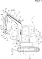
- FIG 40 and FIG 41 are schematic views showing the working machine 1 according to the present invention, and illustrate a backhoe that is a turning working machine.
- the working machine 1 includes a machine body (swivel base) 2, a cabin 3, a traveling device 4, and a work device 5.
- the front side (the left side in FIG 41 ) of the operator seated on the operator seat 6 of the working machine 1 is referred to as the front
- the rear side of the operator (the right side in FIG 41 ) is referred to as the rear
- the left side of the operator (the front surface side of FIG 41 ) is referred to as the left
- the right side of the operator (the back surface side in FIG 41 ) is referred to as the right.
- the horizontal direction K2 (see FIG 40 ), which is a direction orthogonal to the front-rear direction K1 (see FIG 41 ), will be described as a machine width direction.
- the direction from the center portion of the machine body 2 toward the right portion or the left portion thereof will be described as the machine outward direction.
- the machine outward direction is the machine width direction K2 and separates away from the center of the machine body 2 in the width direction.
- the direction opposite to the machine outward direction will be described as the machine inward direction.
- the machine inward direction is the direction of the machine width direction K2 and approaching the center of the machine body 2 in the width direction.
- the machine body 2 is supported and operable to turn on the traveling device 4.
- the machine body 2 has a turn base plate 11 and a weight 12.
- the turn base plate 11 is supported on the frame of the traveling device 4 via a turning bearing, and turns around the vertical axis (vertical axis) by driving the turning motor.
- the weight 12 is attached to the rear portion of the machine body 2.
- the cabin 3 is mounted on the left side and the front side of the machine body 2.
- An operator seat 6 is provided inside the cabin 3.
- the prime mover 13 is an engine, and in this embodiment is a diesel engine.
- the prime mover 13 may be an engine different from the diesel engine such as a gasoline engine, or may be an electric motor.
- the prime mover 13 is provided with an output shaft (crankshaft, power transmission shaft) directed in the machine width direction (left side).
- the hydraulic pump 14 is disposed on the left side of the prime mover 13.
- the fan 23 is disposed on the right side of the prime mover 13.
- the alternator 24 is disposed above the right front portion of the prime mover 13 and outputs DC power for charging the battery.
- the compressor 25 is disposed above the left front portion of the prime mover 13 and compresses the coolant of the air conditioner that cools the cabin 3.
- the radiator 46 is disposed on the right side of the fan 23 and is cooled by driving the fan 23.
- the hydraulic pump 14, the fan 23, the alternator 24, and the compressor 25 are driven by the power of the prime mover 13.
- a operation fluid tank 15, a control valve 26, and a battery (not shown) are disposed on the right side of the machine body 2.
- the operation fluid tank 15 stores hydraulic fluid for operating hydraulic device (such as a hydraulic cylinder described later) provided in the machine body 2.
- the hydraulic fluid stored in the operation fluid tank 15 is delivered to the hydraulic device by driving the hydraulic pump 14.
- the control valve 26 controls the supply of hydraulic fluid to the hydraulic device.
- the traveling device 4 is a crawler-type traveling device, and is provided below the right side and the left side of the machine body 2.
- a dozer device 16 is provided at the front of the traveling device 4.
- the dozer device 16 is driven by a dozer cylinder 37.
- a support bracket 17 is provided at the front of the machine body 2.
- a swing bracket 18 is pivotally supported on the support bracket 17.
- the swing bracket 18 can swing around the vertical axis by driving a swing cylinder 19 mounted on the turn base plate 11.
- the working device 5 is attached to the swing bracket 19.
- the working device 5 includes a boom 8, an arm 9, and a working tool 10.
- a bucket is mounted as the working tool 10, but another working tool (hydraulic attachment) can be mounted instead of or in addition to the bucket.
- other working tools include a hydraulic breaker, a hydraulic crusher, an angle broom, an earth auger, a pallet fork, a sweeper, a mower, and a snow blower.
- the working device 5 includes a boom cylinder 20, an arm cylinder 21, and a working tool cylinder 22 as drive mechanisms (hydraulic actuators) for the boom 8 and the like.
- the boom cylinder 20, the arm cylinder 21, the working tool cylinder 22, the swing cylinder 19, and the dozer cylinder 37 are composed of hydraulic cylinders.
- the base end of the boom 8 is pivotally supported by the swing bracket 18 via the first lateral shaft 31.
- the boom 8 swings up and down around the first lateral shaft 31 through the expansion and contraction of the boom cylinder 20.
- the base end portion of the arm 9 is pivotally supported by the distal end portion of the boom 8 via a second lateral shaft (pivot support shaft) 32.
- the arm 9 swings up and down around the second lateral shaft 32 through the expansion and contraction of the arm cylinder 21.
- the working tool 10 is attached to the tip of the arm 9 via the third lateral shaft 33 and the bracket 50.
- One end of the first link 48 is pivotally supported on the bracket 50 via the fourth lateral shaft 34.
- One end of the second link 49 is pivotally supported on the other end of the first link 48 via a fifth lateral shaft 35.
- the other end of the second link 49 is pivotally supported via the sixth lateral shaft 36 in the vicinity of the distal end of the arm 9 and closer to the base end than the third lateral shaft 33.
- a tip end portion of the working tool cylinder 22 is pivotally supported on the fifth lateral shaft 35.
- the tip end portion of the working tool cylinder 22 is pivotally supported by a third pivot member 29 provided on the tip end of the arm 9, which will be described later.
- the working tool 10 performs a squeeze/dump operation through the expansion and contraction of the working tool cylinder 22.
- the boom 8 has a boom body 81 and a shaft supporting portion 82.
- the boom body 81 is bent with the middle portion being convex along the length direction (direction from the tip end toward the distal end). That is, the boom main body 81 has the bent portion 81a in the middle portion in the length direction.
- the boom body 81 is formed in a substantially rectangular tube shape, and includes a first vertical plate 8a, a second vertical plate 8b, a first lateral plate 8c, and a second lateral plate 8d.
- the first vertical plate 8a is located on one side in the machine width direction.
- the second vertical plate 8b is located on the other side in the machine width direction.
- the first lateral plate 8c connects the first vertical plate 8a and the second vertical plate 8b on one end in the vertical direction.
- the second lateral plate 8d connects the first vertical plate 8a and the second vertical plate 8b on the other end in the vertical direction.
- the first vertical plate 8a is a right plate
- the second vertical plate 8b is a left plate
- the first lateral plate 8c is a lower plate
- the second lateral plate 8d is an upper plate.
- the direction of the boom 8 is based on a state where the boom 8 shown in FIG 40 and FIG 41 is not swinging (a state where the boom 8 extends in the front-rear direction).
- the shaft supporting portion 82 includes a front shaft supporting portion 83 and a rear shaft supporting portion 84.
- the base end portion of the arm 9 is pivotally supported on the front shaft supporting portion 83 via the second lateral shaft (the pivot shaft) 32.
- the rear shaft supporting portion 84 is pivotally supported by the swing bracket 18 via the first lateral shaft 31.
- the front shaft supporting portion 83 and the rear shaft supporting portion 84 are made of cast steel, for example.
- the front shaft supporting portion 83 is located at the tip (front end) of the boom 8. In particular, the front shaft supporting portion 83 is fitted into the distal end portion of the boom body 81 and fixed by welding.
- the rear shaft supporting portion 84 is located at the base end (rear end) of the boom 8. In particular, the rear shaft supporting portion 84 is fitted into the base end portion of the boom body 81 and is fixed by welding.
- the boom 8 is provided with a first pivot member 27 and a second pivot member 28.
- the first pivot member 27 is fixed to the outer surface (lower surface) of the first lateral plate 8c in the middle of the boom body 81 in the length direction. In particular, the first pivot member 27 is fixed to the lower surface of the first lateral plate 8c in the bent portion 81a of the boom body 81.
- one end portion (tip portion) of the boom cylinder 20 is pivotally supported on the first pivot member 27 via a pivot shaft (first pivot shaft) 51.
- the other end (base end) of the boom cylinder 20 is pivotally supported by the swing bracket 18 via a pivot shaft (second pivot shaft) 52.
- the first pivot member 27 has a right plate 27R and a left plate 27L.
- the right plate 27R and the left plate 27L are arranged to face each other with an interval in the machine width direction.
- Each of the right plate 27R and the left plate 27L is provided with a pivot (boss) 271.
- the pivot 271 supports both ends of the first pivot 51. Accordingly, one end portion (tip portion) of the boom cylinder 20 is pivotally supported on the pivot supporting portion 271 via the first pivot shaft 51.
- the second pivot member 28 is fixed to the outer surface (upper surface) of the second lateral plate 8d in the middle of the boom body 81 in the length direction.
- the second pivot member 28 is fixed to the upper surface of the second lateral plate 8d in front of the bent portion 81a of the boom body 81.
- One end (base end) of the arm cylinder 21 is pivotally supported on the second pivot member 28 via a pivot (third pivot) 53.
- the second pivot member 28 has a right plate 28R and a left plate 28L.
- the right plate 28R and the left plate 28L are arranged to face each other with an interval in the machine width direction.
- a second pivot (boss) 281 is provided on each of the right plate 28R and the left plate 28L.
- the second pivot 281 supports both ends of the third pivot 53. Accordingly, one end portion (base end portion) of the arm cylinder 21 is pivotally supported on the second pivot portion 281 via the third pivotal shaft 53.
- a plurality of fluid feeding pipes are fixed to the boom 8 along the length direction of the boom 8.
- a first fluid feeding pipe 56 and a second fluid feeding pipe 57 are provided as a plurality of the fluid feeding pipes.
- the first fluid feeding pipe 56 includes a delivery pipe through which the operation fluid to be sent to the working tool cylinder 22 is passed, and a return pipe through which the operation fluid returning from the working tool cylinder 22 is passed.
- the first fluid feeding pipe 56 extends along the upper surface of the boom body 81.
- the second fluid feeding pipe 57 includes a delivery pipe through which hydraulic fluid delivered to the port 40 passes, and a return pipe through which hydraulic fluid returning from the port 40 passes.
- the port 40 is a so-called service port, and can be connected to a hydraulic hose that supplies hydraulic fluid to the hydraulic actuator that drives the other working tools described above.
- first hydraulic hose 38 is connected to the tip of the first fluid feeding pipe 56.
- second hydraulic hose 39 is connected to the tip of the second fluid feeding pipe 57.
- the first hydraulic hose 38 and the second hydraulic hose 39 extends from the base end of the boom 8 to the distal end.
- the other end of the first hydraulic hose 38 is connected to the working tool cylinder 22.
- the other end of the second hydraulic hose 39 is connected to the service port 40.
- a third pivot member 29 is provided on the base end of the arm 9.
- a pivot (fourth pivot) 54 is supported at the rear of the third pivot member 29.
- the other end portion (tip portion) of the arm cylinder 21 is pivotally supported.
- a pivot (fifth pivot) 55 is supported on the front portion of the third pivot member 29.
- One end (base end) of the working tool cylinder 22 is pivotally supported on the fifth pivot 55.
- the third pivot member 29 has a right plate 29R and a left plate 29L.
- the right plate 29R and the left plate 29L are arranged to face each other with an interval in the machine width direction.
- the right plate 29R supports one side (right side) of the fourth pivot 54 and one side (right side) of the fifth pivot 55.
- the left plate 29L supports the other side (left side) of the fourth pivot 54 and the other side (left side) of the fifth pivot 55.
- the boom cylinder 20 is referred to as a first hydraulic cylinder
- the arm cylinder 21 is referred to as a second hydraulic cylinder.
- the arm cylinder 21 may be a first hydraulic cylinder and the boom cylinder 20 may be a second hydraulic cylinder.
- the boom 8 is provided with a reinforcing plate 60.
- the reinforcing plate 60 includes a front reinforcing plate 60A and a rear reinforcing plate 60B.
- the front reinforcing plate 60A will be described with reference to FIG 3 to FIG 5 .
- the front reinforcing plate 60A is provided inside the boom main body 81 at a position closer to the front of the boom main body 81 (in front of the bent portion 81a). As shown in FIG 4 , the front reinforcing plate 60A is provided at a position ahead of the first pivot 51 and the third pivot 53 (the tip end of the boom 8).
- the front reinforcing plate 60A includes a first supporting portion 61A, a second supporting portion 62A, a first bent portion 63A, a second bent portion 64A, and a connecting portion 65A.
- the first supporting portion 61A, the second supporting portion 62A, the first bent portion 63A, the second bent portion 64A, and the connecting portion 65A are integrally formed by bending a single metal plate.
- the first support 61A is plate-shaped, and one surface (lower surface) thereof is in contact with the inner surface (upper surface) of the first lateral plate 8c.
- the second supporting portion 62A thereof is plate-shaped, and one surface (upper surface) is in contact with the inner surface (lower surface) of the second lateral plate 8d.
- Both or either one of the first supporting portion 61A and the second supporting portion 62A are fixed to the inner surface of the boom body 81 (the upper surface of the first lateral plate 8c and/or the lower surface of the second lateral plate 8d) by welding or the like.
- the first supporting portion 61A is welded to inner surfaces of a first vertical plate 8a, a second vertical plate 8b, and a first lateral plate (lower plate) on substantially the entire circumference (including the first bent portion 63A) of the first supporting portion 61A.
- the second supporting portion 62A is welded to the inner surfaces of the first vertical plate 8a and the second vertical plate 8b, but is not welded to the inner surface of the second lateral plate (upper plate) 8d.
- the welding locations of the first supporting portion 61A and the second supporting portion 62A are not limited to this example.
- the width (length in the machine width direction) of the first supporting portion 61A is set to be equal to or greater than the distance between the outer surface (left surface) of the right plate 27R of the first pivot member 27 and the outer surface (right surface) of the left plate 27L.
- the width (length in the machine width direction) of the second supporting portion 62A is set to be equal to or greater than the distance between the outer surface (left surface) of the right plate 28R of the second pivot member 28 and the outer surface (right surface) of the left plate 28L.
- the first bent portion 63A is bent from the first supporting portion 61A toward the second lateral plate 8d.
- the first bent portion 63A is adjoining to the inner surface of the first lateral plate 8c in a region where it overlaps the first pivot member 27 with the first lateral plate 8c inbetween.
- the first bent portion 63A is adjoining to the inner surface of the first lateral plate 8c between the end portion (front end portion) 27a of the first pivot member 27 and the pivot supporting portion 271 in the boom length direction, in the region where it overlaps the front portion of the first pivot member 27 with the first lateral plate 8c interposed therebetween.
- the first supporting portion 61A extends from the first bent portion 63A along the inner surface of the first lateral plate 8c in a direction away from the pivot supporting portion 271 (a direction away from the first pivot shaft 51). Also, the first supporting portion 61A extends from the first bent portion 63A along the inner surface of the first lateral plate 8c in a direction away from the second pivot portion 281 (a direction away from the third pivotal axis 53). In particular, the first supporting portion 61A extends from the first bent portion 63A to the front (the tip side of the boom 8) along the upper surface of the first lateral plate 8c.
- the first supporting portion 61A has an extension length extending from the first bent portion 63A, which varies in the machine width direction.
- portions (maximum extension portions) 61a having the maximum extension length from the first bent portion 63A are provided respectively on one side and the other side in the machine width direction, and a portion (minimum extension portion) 61b having the minimum extension length from the first bent portion 63A is provided at the center in the machine width direction.
- a space between the extension end of the maximum extension portion 61a and the extension end of the minimum extension portion 61b is formed in an arc shape.
- the maximum extension portion 61a is in contact with the inner surface of the first lateral plate 8c at a position overlapping the left plate 27L and the right plate 27R via the first lateral plate 8a.
- the minimum extension portion 61b is in contact with the inner surface of the first lateral plate 8c at a position between the left plate 27L and the right plate 27R.
- the front end of the first supporting portion 61A (the extension end of the maximum extension portion 61a) is located in front of the front end 27a of the first pivot member 27.
- the rear end of the first supporting portion 61A (boundary portion with the first bent portion 63A) is located behind the front end 27a of the first pivot member 27. That is, the front end 27a of the first pivot member 27 is located between the front end and the rear end of the first supporting portion 61A in the front-rear direction.
- the second bent portion 64A is bent from the second supporting portion 62A toward the first lateral plate 8c.
- the second bent portion 64A is close to the inner surface of the second lateral plate 8d in a region overlapping the front portion of the second pivot member 28 via the second lateral plate 8d.
- the second supporting portion 62A extends from the second bent portion 64A along the inner surface of the second lateral plate 8d in a direction away from the pivot portion 271 (a direction away from the first pivot axis 51). Also, the second supporting portion 62A extends from the second bent portion 64A along the inner surface of the second lateral plate 8d in a direction away from the second pivotal portion 281 (a direction away from the third pivot 53). In particular, the second supporting portion 62A extends forward (towards the tip end of the boom 8) along the lower surface of the second lateral plate 8d from the second bent portion 64A.
- the extension length of the second supporting portion 62A extending from the second bent portion 64A which varies in the machine width direction.
- portions (maximum extension portions) 62a having the maximum extension length from the second bent portion 64A are provided respectively on one side and the other side in the machine width direction
- a portion (minimum extension portion) 62b having the minimum extension length from the second bent portion 64A is provided at the center in the machine width direction.
- a space between the extension end of the maximum extension portion 62a and the extension end of the minimum extension portion 62b is formed in an arc shape.
- the maximum extension portion 62a supports the inner surface of the second lateral plate 8d at a position overlapping the left plate 28L and the right plate 28R via the second lateral plate 8d.
- the minimum extension portion 62b is in contact with the inner surface of the second lateral plate 8d at a position between the left plate 28L and the right plate 28R.
- the front end of the second supporting portion 62A (the extension end of the maximum extension portion 62a) is located in front of the front end 28a of the second pivot member 28.
- the rear end of the second supporting portion 62A (the boundary portion with the second bent portion 64A) is located behind the front end 28a of the second pivot member 28. That is, the front end of the second pivot member 28 is located between the front end and the rear end of the second supporting portion 62A in the front-rear direction.
- the connecting portion 65A connects the first bent portion 63A and the second bent portion 64A.
- the connecting portion 65A inclines to the front (towards the front end of the boom 8) as it extends from the first supporting portion 61A to the second supporting portion 62A.
- first bent portion 63A and the second bent portion 64A are bent at an acute angle, and the other one is bent at an obtuse angle.
- first bent portion 63A is bent at an acute angle
- second bent portion 64A is bent at an obtuse angle.
- the rear reinforcing plate 60B is provided inside the boom main body 81 at a position closer to the rear of the boom main body 81 (behind the bent portion 81a). As shown in FIG 4 , the rear reinforcing plate 60B is provided at a position rearward of the first pivot 51 and the third pivot 53 (the base end of the boom 8).
- the rear reinforcing plate 60B includes a first supporting portion 61B, a second supporting portion 62B, a first bent portion 63B, a second bent portion 64B, and a connecting portion 65B.
- the first supporting portion 61B, the second supporting portion 62B, the first bent portion 63B, the second bent portion 64B, and the connecting portion 65B are integrally formed by bending a single metal plate.
- the first supporting portion 61B is plate-shaped, and one surface (lower surface) is in contact with the inner surface (upper surface) of the first lateral plate 8c.
- the second supporting portion 62B is plate-shaped, and one surface (upper surface) is in contact with the inner surface (lower surface) of the second lateral plate 8d.
- Both or either one of the first supporting portion 61B and the second supporting portion 62B are fixed to the inner surface of the boom body 81 (the upper surface of the first lateral plate 8c and/or the lower surface of the second lateral plate 8d) by welding or the like.
- the first bent portion 63B is bent from the first supporting portion 61B toward the second lateral plate 8d.
- the first bent portion 63B is close to the inner surface of the first lateral plate 8c in a region where it overlaps the rear portion of the first pivot member 27 with the first lateral plate 8a interposed therebetween.
- the first supporting portion 61B extends from the first bent portion 63B along the inner surface of the first lateral plate 8c in a direction away from the pivot portion 271 (a direction away from the first pivot axis 51).
- the first supporting portion 61B extends rearward (to the base end of the boom 8) along the upper surface of the first lateral plate 8c from the first bent portion 63B.
- the first supporting portion 61B has an extension length from the first bent portion 63B, which varies in the machine width direction.
- portions (maximum extension portions) 61c having the maximum extension length from the first bent portion 63B are provided respectively on one side and the other side in the machine width direction, and a portion (minimum extension portion) 61d having a minimum extension length from the first bent portion 63B is provided at the center in the machine width direction.
- a space between the extension end of the maximum extension portion 61c and the extension end of the minimum extension portion 61d is formed in an arc shape.
- the maximum extension portion 61c is in contact with the inner surface of the first lateral plate 8c at a position overlapping the left plate 27L and the right plate 27R via the first lateral plate 8c.
- the minimum extension portion 61d is in contact with the inner surface of the first lateral plate 8c at a position between the left plate 27L and the right plate 27R.
- the rear end of the first supporting portion 61B (the extension end of the maximum extension portion 61a) is located behind the rear end 27b of the first pivot member 27.
- the front end of the first supporting portion 61B (the boundary portion with the first bent portion 63B) is located in front of the rear end 27b of the first pivot member 27. That is, the rear end 27b of the first pivot member 27 is located between the front end and the rear end of the first supporting portion 61B in the front-rear direction.
- the second bent portion 64B is bent from the second supporting portion 62B toward the first lateral plate 8c side.
- the second bent portion 64A is close to the inner surface of the second lateral plate 8d.
- the second supporting portion 62B extends from the second bent portion 64B along the inner surface of the second lateral plate 8d in a direction away from the pivot portion 271 (a direction separating away from the first pivotal axis 51). In particular, the second supporting portion 62B extends rearward (to the base end of the boom 8) from the second bent portion 64B along the lower surface of the second lateral plate 8d.
- the extension length extending from the second bent portion 64B of the second supporting portion 62B which varies in the machine width direction.
- portions (maximum extension portions) 62c having the maximum extension length from the second bent portion 64B are provided respectively on one side and the other side in the machine width direction, and a portion (minimum extension portion) 62d having the minimum extension length from the second bent portion 64B is provided at the center in the machine width direction.
- a space between the extension end of the maximum extension portion 62c and the extension end of the minimum extension portion 62d is formed in an arc shape.
- the connecting portion 65B connects the first bent portion 63B and the second bent portion 64B.
- the connecting portion 65B inclines rearward (the base end of the boom 8) as it extends from the first supporting portion 61B toward the second supporting portion 62B. Accordingly, the connecting portion 65A leans forward as it extends from the first supporting portion 61A to the second supporting portion 62A, and the connecting portion 65B leans backward as it extends from the first supporting portion 61B to the second supporting portion 62B.
- the entire bending deformation of the boom 8 can be effectively prevented by the front reinforcing plate 60A arranged in front of the bent portion 81a and the rear reinforcing plate 60B arranged behind the bent portion 81a.
- first bent portion 63B and the second bent portion 64B is bent at an acute angle, and the other one is bent at an obtuse angle.
- first bent portion 63B is bent at an acute angle
- second bent portion 64B is bent at an obtuse angle. This increases the strength of the reinforcement plate 60 significantly in the first bent portion 63A, so that the reinforcement effect can be improved.
- first bent portion 63A and the second bent portion 64A is bent at an acute angle and the other one is bent at an obtuse angle, even when the first pivot member 27 is spaced away from the second pivot member 28 in the boom length direction, the first lateral plate 8c and the second lateral plate 8d can be effectively reinforced by the single reinforcing plate 60.
- the first lateral plate 8c is the lower plate and the second lateral plate 8d is the upper plate.
- the first lateral plate 8c may be the upper plate and the second lateral plate 8d may be the lower plate.
- the pivot member fixed to the outer surface (upper surface) of the upper plate is the first pivot member 27, and the pivot member fixed to the outer surface (lower surface) of the lower plate is the second pivot member 28.
- the arm cylinder 21 is a first hydraulic cylinder
- the boom cylinder 20 is a second hydraulic cylinder.
- the reinforcing plate 60 has a configuration in which the first supporting portion 61A abuts on the inner surface of the upper plate and the second supporting portion 62A abuts on the inner surface of the lower plate.
- the reinforcing plate 60 (the front reinforcing plate 60A and the rear reinforcing plate 60B) includes the first supporting portion 61 A, the second supporting portion 62A, the first bent portion 63B, the second bent portion 64B, and the connecting portion 65B.
- the reinforcement plate 60 should just have the first supporting portion 61A and the first bent portion 63B. That is, the reinforcing plate 60 may be a plate bent in a substantially L shape.
- the front reinforcing plate 60A is a plate bent in a substantially L shape will be described.
- the description of the rear reinforcing plate 60B is omitted, but a modification example similar to that of the front reinforcing plate 60A can be adopted.
- FIG 7 and FIG 8 show a modification example of the case where the front reinforcing plate 60A is a plate bent in a substantially L shape.
- the front reinforcing plate 60A in these modification examples is composed of a first supporting portion 61A, a first bent portion 63A, and a first extending portion 66A.
- the first lateral plate 8c is the lower plate and the second lateral plate 8d is the upper plate.
- the first supporting portion 61A is in contact with the inner surface (upper surface) of the first lateral plate (lower plate) 8c.
- the first supporting portion 61A is fixed to the inner surface of the first lateral plate 8c by welding or the like.
- the first bent portion 63A is bent to extend from the first supporting portion 61A toward the second lateral plate (upper plate) 8d, and is close to the inner surface of the first lateral plate 8c in a region overlapping the front portion of the first pivot member 27 with the first lateral plate 8c interposed therebetween .
- the first bent portion 63A is bent at an acute angle.
- the first supporting portion 61A extends from the first bent portion 63A along the inner surface of the first lateral plate 8c in a direction away from the pivot supporting portion 271 (a direction away from the first pivot shaft 51).
- the first extending portion 66A extends from the first bent portion 63A toward the second lateral plate 8d and contacts the inner surface (lower surface) of the second lateral plate 8d.
- the first extending portion 66A may be connected to the inner surface of the second lateral plate 8d by welding or the like.
- the first lateral plate 8c is an upper plate and the second lateral plate 8d is a lower plate. Further, the pivot member fixed to the outer surface (upper surface) of the first lateral plate 8c is the first pivot member 27, and the pivot member fixed to the outer surface (lower surface) of the second lateral plate 8d is the second pivot member 28.
- the arm cylinder 21 is a first hydraulic cylinder and the boom cylinder 20 is a second hydraulic cylinder.
- the first supporting portion 61A is in contact with the inner surface (lower surface) of the first lateral plate (upper plate) 8c.
- the first supporting portion 61A is fixed to the inner surface of the first lateral plate 8c by welding or the like.
- the first bent portion 63A is bent from the first supporting portion 61A toward the second lateral plate (lower plate) 8d and is close to the inner surface of the first lateral plate 8c in a region overlapping the front portion of the first pivot member 27 with the first lateral plate 8c interposed therebetween.
- the first bent portion 63A is bent at an obtuse angle.
- the first supporting portion 61A extends from the first bent portion 63A along the inner surface of the first lateral plate 8c in a direction away from the second pivot portion 281 (a direction away from the third pivotal axis 53).
- the first extending portion 66A extends from the first bent portion 63A toward the second lateral plate 8d and contacts the inner surface of the second lateral plate 8d.
- the first extending portion 66A may be connected to the inner surface of the second lateral plate 8d by welding or the like.
- the front shaft supporting portion 83 provided on the distal end of the boom 8 includes a first bearing portion 85, a second bearing portion 86, and a connecting portion 87.
- the first bearing portion 85 extends forward from the tip of the boom body 81 on one side (right side) in the machine width direction.
- the second bearing portion 86 extends forward from the tip of the boom body 81 on the other side (left side) in the machine width direction.
- the first bearing portion 85 supports one side (right side) of the second lateral shaft (pivot shaft) 32.
- the second bearing portion 86 supports the other side (left side) of the second lateral shaft 32.
- the connecting portion 87 connects the first bearing portion 85 and the second bearing portion 86.
- the connecting portion 87 connects the rear portion of the inner surface (left surface) of the first bearing portion 85 and the rear portion of the inner surface (right surface) of the second bearing portion 86.
- the first bearing portion 85 and the second bearing portion 86 are bifurcated from the connecting portion 87 and extend forward.
- the upper surface 87a of the connecting portion 87 is formed as an inclined surface that shifts downward as it extends forward.
- a first concave portion 88 that is recessed downward (toward the lower surface 87b) is formed on the upper surface 87a of the connecting portion 87.
- the first concave portion 88 is formed on the upper surface 87a which is an inclined surface.
- the first concave portion 88 is recessed in a direction (front-rear direction) from the tip end of the boom 8 toward the distal end thereof.
- the first concave portion 88 is also recessed in the width direction (machine width direction) from the first bearing portion 85 toward the second bearing portion 86.
- the upper surface 87a has a first inclining portion 87f having a larger (steep) inclination in the front-rear direction, and has a second inclining portion 87g having a smaller (gradual) inclination than that of the first inclining portion 87f.
- Both the first inclining portion 87f and the second inclining portion 87g are inclined with respect to the extending direction (length direction) of the boom 8.
- the upper surface 87a has, on one side, a first curved surface 87h that lowers toward the other side and has, on the other side, a second curved surface 87i that lowers toward the other side in the machine width direction, and a flat surface 87j connecting the first curved surface 87e and the second curved surface 87f at the center.
- the first concave portion 88 is provided with a holding portion 30 that holds the first hydraulic hose 38.
- the holding portion 30 is attached to the bottom (the most recessed portion) of the recess of the first concave portion 88.
- the holding portion 30 is attached to a boundary portion between the first inclining portion 87f and the second inclining portion 87g in the front-rear direction.
- the holding portion 30 is positioned on the flat surface 87j in the machine width direction.
- the holding portion 30 includes a base plate 30a and a holding body 30b.
- the base plate 30a is fixed to the first concave portion 88 by a fixture (bolt) 30c.
- the holding body 30b holds the first hydraulic hose 38 in the vicinity of the first concave portion 88 by pressing the first hydraulic hose 38 from above (restricting the upward movement).
- the holding portion 30 holds two hydraulic hoses, but may hold three or more hydraulic hoses.
- the lower surface 87b of the connecting portion 87 is formed as an inclined surface that is inclined with respect to the extending direction (length direction) of the boom 8.
- the lower surface 87b is formed as an inclined surface that shifts upward as it extends forward.
- the inclined surface is formed with a second concave portion 89 that is recessed upward (toward the upper surface 87a) in the machine width direction.
- the second concave portion 89 is arranged so as to define the lower surface 87b, on one side, a third curved surface 87k that lowers toward the other side in the machine width direction, on the other side, a fourth curved surface 87m that lowers toward one side, and, in the center, a flat surface 87n which connects the third curved surface 87k and the fourth curved surface 87m.
- the rear end portion 87c of the inclined surface formed on the upper surface 87a of the connecting portion 87 is located behind the rear end portion 87d of the inclined surface formed on the lower surface 87b of the connecting portion 87.
- the inclination angle of the upper surface 87a (inclination angle with respect to the upper surface of the boom body 81) is formed more gently than the inclination angle of the lower surface 87b (inclination angle with respect to the lower surface of the boom body 81).
- the inclination angle of the upper surface 87a and the inclination angle of the lower surface 87b may be designed to be same.
- the connecting portion 87 extends forward near the middle between the first bearing portion 85 and the second bearing portion 86 in the vertical direction.
- the front end 87e of the connecting portion 87 is positioned below a first straight line (virtual straight line) L1 that connects the upper end of the second lateral shaft (pivot support shaft) 32 and the midpoint 81M of the rear end of the front shaft supporting portion 83 in the vertical direction.
- the front end 87e of the connecting portion 87 is located above a second straight line (virtual straight line) L2 connecting the lower end of the second lateral shaft 32 and the midpoint 81M.
- the front end 87e of the connecting portion 87 is located below a third straight line (virtual straight line) L3 that connects the axial center 32C of the second lateral shaft 32 and the midpoint 81M of the rear end of the front shaft supporting portion 83 in the vertical direction.
- the front end 87e of the connecting portion 87 may be located on the third straight line L3, not below the third straight line L3, or may be located above the third straight line L3.
- the first hydraulic hose 38 extending forward along the upper surface of the boom body 81 (the upper surface of the second lateral plate 8d) is held by the holding portion 30.
- the first hydraulic hose 38 guided along the upper surface 87a of the connecting portion 87 passes between the front end 87e of the connecting portion 87 and the second lateral shaft 32, and is connected to the working tool cylinder 22 after being guided to the left plate 29L and the right plate 29R of the third pivot member 29.
- the first hydraulic hose 38 is guided along the upper surface 87a of the connecting portion 87, but because a sufficient space is secured above the connecting portion 87 by the first concave portion 88, in addition to the first hydraulic hose 38, the second hydraulic hose 39 may be also guided along the upper surface 87a.
- the second hydraulic hose 39 may be arranged outside of the front shaft supporting portion 83 (the machine outward) (see FIG 1 ), or arranged along the upper surface 87a of the connecting portion 87.
- the connecting portion 87 has a recess on both the upper surface 87a and the lower surface 87b, but it is only necessary to have a recess on at least one the upper surface 87a and the lower surface 87b. That is, a structure which has a recessed portion only in the upper surface 87a may be employed, or a structure which has a recessed portion only in the lower surface 87b may be employed.
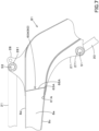
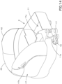
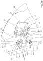
- a cover 41 is provided on one side of the machine body 2 in the width direction.
- the cover 41 is provided on the right side of the machine body 2 and on the right side of the cabin 3. As shown by the image line in FIG 40 , it can be opened upward and toward the machine outward (toward the right outside) around the right front portion of the machine body 2.
- a grip 41a that can be gripped when the operator opens the cover 41 is provided at the right rear portion of the cover 41.
- the cover 41 covers the upper, right and front sides of the operation fluid tank 15 and the control valve 26.
- the operation fluid tank 15 is mounted on the right rear portion of the turn base plate 11.
- the operation fluid tank 15 has a substantially rectangular parallelepiped shape, of which size in the height direction is longer than those in the front-rear direction and the machine width direction. That is, the operation fluid tank 15 is arranged vertically.
- a control valve 26 is attached to the front surface of the operation fluid tank 15 via a mounting bracket 46.
- the control valve 26 is a valve unit in which a plurality of valves are aligned and integrated, and the plurality of valves are arranged side by side in the height direction (vertical direction). That is, the control valve 26 is arranged vertically.
- the plurality of valves constituting the control valve 26 include a swing control valve that controls the supply of hydraulic fluid to the swing cylinder 19, a boom control valve that controls the supply of hydraulic fluid to the boom cylinder 20, an arm control valve for controlling the supply of hydraulic fluid to the arm cylinder 21, a working tool control valve for controlling the supply of hydraulic fluid to the working tool cylinder 22, a dozer control valve for controlling the supply of hydraulic fluid to the dozer cylinder 37, a turn motor control valve for turning to control the supply of hydraulic fluid to the turn motor, a traveling control valve for controlling the supply of hydraulic fluid to the travel motor of the traveling device 4, and a service port control valve for controlling the supply of hydraulic fluid to the hydraulic attachment.
- a swing control valve that controls the supply of hydraulic fluid to the swing cylinder 19
- a boom control valve that controls the supply of hydraulic fluid to the boom cylinder 20
- an arm control valve for controlling the supply of hydraulic fluid to the arm cylinder 21
- a working tool control valve for controlling the supply of hydraulic fluid to the working tool cylinder 22
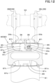
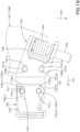
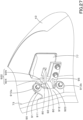
- a supporting member 150 is provided in front of the control valve 26.
- the supporting member 150 is provided on one side in the machine width direction.
- the supporting member 150 is provided in the right front portion of the machine body 2.
- the upper side, the right side (one side in the machine width direction) and the front side of the supporting member 150 are covered with a cover 41.
- the supporting member 150 includes a first supporting member 151 and a second supporting member 152.
- the first supporting member 151 is attached to the machine body 2 via a base member 159.
- the base member 159 includes a bracket 160 and a base platform 161.
- the bracket 160 is fixed to the machine body 2.
- the bracket 160 is fixed to the side surface (right surface) of the machine outward side of the longitudinal rib 11a extending in the front-rear direction on the turn base plate 11.
- the base platform 161 is fixed to the upper portion of the bracket 160 with bolts and extends toward the outside (right side) of the machine body.
- a first supporting member 151 is attached to the base platform 161.
- the first supporting member 151 has a base plate portion 151a and a first plate portion 151b.
- the base plate portion 151a is connected to the upper surface of the base platform 161 by a connecting member (bolt) 158 and extends rearward (to the control valve 26). As shown in FIG 18 and FIG 19 , the base plate portion 151a is provided with the fourth holes 151d. Each of the fourth holes 151d is an oval hole formed, of which length in the front-rear direction is longer than the length in the machine width direction. The fourth hole 151d penetrates the base plate portion 151a in the vertical direction. An inserting portion (screw shaft) 159a of the connecting member 158 is inserted into the fourth hole 151d. The inserting portion 159a of the connecting member 158 is screwed into a fifth hole (screw hole) 161a provided in the base plate 161.
- first holes 151c are formed in the first plate portion 151b.
- the first hole 151c is a screw hole that penetrates the first plate portion 151b in the vertical direction.
- the first plate portion 151b is connected to the upper surface of the rear portion of the base plate portion 151a by welding or the like, and extends rearward from the base plate portion 151a.
- the base plate portion 151a and the first plate portion 151b are configured from separated members, but may be configured from a single member.
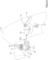
- a support tool 162 is fixed to the upper surface of the first supporting member 151 (the upper surface of the base plate portion 151a).
- the support tool 162 supports a fulcrum shaft 163 that is an opening/closing fulcrum of the cover 41.
- the fulcrum shaft 163 is arranged substantially parallel (substantially horizontally) to the upper surface of the turn base plate 11. As shown in FIG 5 , the fulcrum shaft 163 extends in a direction of moving to the rear K4 as it shifts outward of the machine body K3.
- One end of the coil spring 164 is fixed to the fulcrum shaft 163.
- the other end of the coil spring 164 is fixed to the support tool 162.
- the coil spring 164 biases the fulcrum shaft 163 in one direction around the axis (the direction in which the cover 41 closes).
- an swing body 165 is attached to the fulcrum shaft 163.
- the swing body 165 swings around the axis of the fulcrum shaft 163.
- the swing body 165 has a fulcrum shaft attachment portion 165a, an extending portion 165b, and an attachment plate 165c.
- the fulcrum shaft attachment portion 165a is attached to one end (outside the machine body) of the fulcrum shaft 163.
- the extending portion 165b includes a lateral extending portion 165b1 and a vertical extending portion 165b2.
- the lateral extending portion 165b1 extends from the fulcrum shaft attachment portion 165a outward and rearward of the machine body.
- the vertical extending portion 165b2 extends upward from the extending end of the horizontally extending portion 165b1.
- the attachment plate 165c is fixed to the upper portion and the lower portion of the vertical extending portion 165b2.
- the attachment plate 165c is attached to the inner surface of the right front portion of the cover 41 by means of a bolt to secure the cover 41 with the swing body 165.
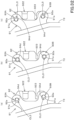
- an attachment shaft 155 is fixed to the lower surface of the first supporting member 151 (the lower surface of the first plate portion 151b).
- a stopper plate 156 is attached to the attachment shaft 155 so as to be rotatable around the axis of the attachment shaft 155.
- the stopper plate 156 restricts the rotation range when the cover 41 is opened and closed.
- the stopper plate 156 has an oval hole, and a projecting shaft provided on the fulcrum shaft attachment portion 165a is movably inserted into the oval hole.
- the protruding shaft can move along the oval hole as the swing body 165 swings, and the rotation range of the cover 41 is restricted by the movable range (length of the elongated hole).
- the second supporting member 152 is attached to the first supporting member 151.
- the second supporting member 152 is formed in a substantially L shape having a horizontal portion (second plate portion) 152a and a vertical portion 152b, and the horizontal portion 152a is attached to the first supporting member 151.
- Second holes 152c are formed in the horizontal portion 152a.
- the second holes 152c penetrate the horizontal portion 152a in the vertical direction.
- the number of the second holes 152c is the same as that of the first holes 151c provided in the first supporting member 151, and is two in the present embodiment.
- a mounting portion 152d is provided on the vertical portion 152b.
- a switching valve 170 is attached to the attachment portion 152d.
- the attachment portion 152d has an attachment hole 152e, and the switching valve 170 is attached by a bolt inserted into the attachment hole 152e. As shown in FIG 15 , the upper side, the right side (one side in the machine width direction) and the front side of the switching valve 170 are covered with the cover 41.
- the switching valve 170 is a three-way switching valve.
- the switching valve 170 is a valve that switches the state of the hydraulic fluid supply path for a hydraulic device (for example, a hydraulic attachment or the like).
- the switching valve 170 is a so-called third-line valve, and is a valve that enables the hydraulic fluid to be returned to the operation fluid tank 15 without the control valve 26 by a switching operation.
- the switching valve 170 may be a valve other than the third line valve.
- the switching valve 170 has an inlet port 171, a first outlet port 172, a second outlet port 173, and an operation handle 174.
- the switching valve 170 operates the operation handle 174 to switch the outer ports of the hydraulic fluid introduced from the inlet port 171 to a first state where the first outlet port 172 is used and to a second state where the second outlet port 173 is used.
- a third hydraulic hose 175 is connected to the inlet port 171.
- the third hydraulic hose 175 is connected to a hydraulic device (for example, a hydraulic attachment or the like), and defines a return fluid line for returning the hydraulic fluid from the hydraulic device to the operation fluid tank 15.
- a fourth hydraulic hose 176 is connected to the first outlet port 172.
- the fourth hydraulic hose 176 is connected to the inlet port of the control valve 26.
- a fifth hydraulic hose 177 is connected to the second outlet port 173.
- the fifth hydraulic hose 177 is connected to the operation fluid tank 15.
- the hydraulic fluid introduced from the inlet port 171 through the third hydraulic hose 175 exits from the first outlet port 172 and enters the control valve 26 through the fourth hydraulic hose 176.
- the hydraulic fluid introduced from the inlet port 171 exits the second outlet port 173 and returns to the operation fluid tank 15 through the fifth hydraulic hose 177 without entering the control valve 26.
- the first supporting member 151 and the second supporting member 152 are connected by a connecting member 178.
- the connecting member 178 has an inserting portion 178a that is inserted into the first hole 151c and the second hole 152c.
- the connecting member 178 is a bolt
- the inserting portion 178a is a screw shaft of the bolt.
- the connection between the first supporting member 151 and the second supporting member 152 by the connecting member 178 is performed by placing the horizontal portion (second plate portion) 152a of the second supporting member 152 above (or below) the first plate portion 151b of the first supporting member 151.
- the first hole 151c and the second hole 152c are overlapped, the inserting portion 178a of the connecting member 178 is inserted into the second hole 152c, and the inserting portion 178a is screwed into the first hole 151c which is a screw hole.
- the first hole 151c may be a through hole that is not a screw hole, then a nut may be screwed into the inserting portion 178a inserted into the through hole, and thereby the first supporting member 151 and the second supporting member 152 are connected.
- the supporting member 150 may be assembled to the machine body 2 after the first supporting member 151 and the second supporting member 152 are connected (sub-assembled) by the connecting member 178.
- At least one of the first supporting member 151 and the second supporting member 152 has a position adjustment portion 153.
- the position adjustment portion 153 is operable to adjust the relative position between the first supporting member 151 and the second supporting member 152. In other words, the position adjustment portion 153 can adjust the position of the second supporting member 152 relative to the first supporting member 151.
- the position adjustment portion 153 includes at least one of a first hole 151c provided in the first supporting member 151 and a second hole 152c provided in the second supporting member 152.
- the hole (at least one of the first hole 151c and the second hole 152c) is formed in a size having a gap (clearance) with respect to the outer diameter of the inserting portion 178a of the connecting member 178. That is, the position adjustment portion 153 includes a hole formed in a size having a gap with respect to the outer diameter of the inserting portion 178a.
- the second hole 152c is formed in a size having a gap (that is, the second hole 152c is included in the position adjusting unit 153).
- first hole 151c is a through-hole that is not a screw hole (when a nut is used)
- either or both of the first hole 151c and the second hole 152c may be formed in a size having a gap with respect to the outer diameter of the inserting portion 178a.
- one or both of the first hole 151c and the second hole 152c are included in the position adjustment portion 153.
- the method of forming the first hole 151c and/or the second hole 152c with a size having a gap is, for example, a method of making the diameter (inner diameter) of the circular hole larger than the outer diameter of the inserting portion 178a, or a method of forming a shape of the hole to be a shape other than a circle such as an oval hole.
- the latter method is adapted.
- the first hole 151c is a screw hole
- one of the two second holes 152c is an oval hole.
- the number of the first holes 151c and the second holes 152c may be respectively one, but is preferably in plural. When the number of the first holes 151c and the second holes 152c is in plural, at least one of the holes may be formed in a size having a gap. In the case of this embodiment, the second hole 152c1 of the two second holes 152c is formed in a size having a gap. In addition, when the number of the first holes 151c and the second holes 152c is in plural, it is preferable that the plural holes are formed side by side in the machine width direction. In the case of the present embodiment, two first holes 151c are formed side by side in the machine width direction, and two second holes 152c are also formed side by side in the machine width direction.
- FIG 19 shows a case where the two first holes 151c are formed as screw holes, and the hole 152c1 of the two second holes 152c (the machine inward side) is formed in a size having a gap CL1.
- the second hole 152c1 is formed as a long hole that is longer in the front-rear direction than that in the machine width direction.
- a solid line indicates a state where the rear portion of the second hole 152c1 overlaps the first hole 151c
- a virtual line indicates a state where the front portion of the second hole 152c1 overlaps the first hole 151c.
- the outer diameter of the inserting portion 178a of the connecting member 178 overlaps the inner diameter of the first hole 151c, and the gap CL1 is formed between the inserting portion 178a and the second hole 152c1.
- the gap CL1 By forming the gap CL1 in this manner, the position of the second hole 152c1 with respect to the first hole 151c can be shifted from the solid line position to the virtual line position. That is, the position of the second supporting member 152 relative to the first supporting member 151 can be adjusted. In particular, the rotational movement of the second plate portion 152c relative to the first plate portion 151b can be allowed.
- the linear movement of the second board portion 152c with respect to the first board portion 151b is also permitted by forming both the two second holes 152c to be oval holes. That is, the gap CL1 may allow rotational movement of the second supporting member 152 relative to the first supporting member 151, may allow linear movement, or may allow both movements. It is preferable that the movement of the second supporting member 152 with respect to the first supporting member 151 includes movement in the machine width direction (the machine outward direction or the machine inward direction) regardless of whether it is the rotational movement or the linear movement.
- a fulcrum shaft 163 serving as an opening/closing fulcrum of the cover 41 is attached to the first supporting member 151.
- a switching valve 170 is attached to the second supporting member 152.
- the first supporting member 151 has a second position adjustment portion 154.
- the second position adjustment portion 154 can adjust the position of the first supporting member 151 relative to the machine body 2.
- the second position adjustment portion 154 makes it possible to adjust the position of the first supporting member 151 with respect to the base member 159 (base plate 161).
- the second position adjustment portion 154 includes a fourth hole 151d provided in the first supporting member 151.
- the connecting member 158 that connects the first supporting member 151 and the base member 159 (the base plate 161) has an inserting portion 158a that is inserted into the fourth hole 151d and the fifth hole 161a.
- the connecting member 158 is a bolt
- the inserting portion 158a is a screw shaft of the bolt.
- the fourth hole 151d is a long hole
- the fifth hole 161a is a screw hole.
- a gap CL2 is formed between the inserting portion 158a of the connecting member 158 and the fourth hole 151d.
- the fourth hole 151d constituting the second position adjusting portion 154 is formed to have a size having a gap with respect to the outer diameter of the inserting portion (screw shaft) 158a.
- a solid line indicates a state where the rear portion of the fourth hole 151d overlaps the screw hole 161a
- an image line indicates a state where the front portion of the fourth hole 151d overlaps the screw hole 161a.
- the gap CL2 is formed between the inserting portion 158a and the fourth hole 151d.
- the position of the fourth hole 151d with respect to the screw hole 161a can be shifted from the solid line position to the virtual line position. That is, the position of the fourth hole 151d with respect to the screw hole 161a can be adjusted in the gap CL2. Thereby, the position of the first supporting member 151 with respect to the base member 159 can be adjusted. Thus, the position of the fulcrum shaft 163 and the position of the cover 41 with respect to the machine body 2 can be adjusted.
- the second position adjustment portion 154 performs position adjustment of the first supporting member 151 with respect to the base member 159 through the linear movement, but instead of or in addition to adjustment through the linear movement, adjustment through the rotational movement may be allowed.
- the change in the moving direction can be realized by changing the shape and size of the fourth hole 151d provided in the base plate portion 151a.
- a bonnet 43 is provided at the rear portion of the machine body 2.
- the bonnet 43 is provided so as to be openable and closable with respect to the machine body 2 and covers the rear portion of the prime mover 13.
- the bonnet 43 is supported by a support leg 70 standing on the rear portion of the turn base plate 11.
- the support leg 70 includes a first leg 71, a second leg 72, a third leg 73, a fourth leg 74, and a support base 75.
- the first leg 71 is provided standing on the right front side of the prime mover 13.
- the second leg 72 is provided standing on the left front side of the prime mover 13.
- the third leg 73 is provided standing on the right rear side of the prime mover 13.
- the fourth leg 74 is provided standing on the left rear side of the prime mover 13.
- the upper portions of the first leg 71 and the second leg 72 are bent toward the rear.
- the upper portions of the third leg 73 and the fourth leg 74 are bent toward the front.
- the support base 75 is provided extending in the machine width direction, and connects the upper portion of the first leg 71, the upper portion of the second leg 72, the upper portion of the third leg 73, and the upper portion of the fourth leg 74.
- a rotation support member 44 that constitutes a rotation fulcrum of the bonnet 43 is attached to the fourth leg 74.
- the rotation support member 44 includes a first fixed portion 44a, a second fixed portion 44b, a movable portion 44c, and a support shaft 44d.
- the first fixed portion 44a is fixed to the rear surface of the fourth leg 74.
- the second fixed portion 44b is fixed to the inner surface of the second cover 42 arranged on the left side of the bonnet 43.
- the movable portion 44c is bent in a substantially U-shape in a plan view. One end portion of the movable portion 44c is connected to the fixed portion 44a via a support shaft 44d.
- the other end portion of the movable portion 44c is fixed to the inner surface of the left portion of the bonnet 43 through an attachment plate 44e.
- the support shaft 44d extends in the vertical direction.
- the movable portion 44c is configured to be rotated forward or backward around the support shaft 44d.
- the bonnet 43 turns backward to be opened (see FIG 25 ).
- the bonnet 43 turns forward to be closed (see FIG 24 ).
- a latching piece 80 is provided on one side (left portion) of the bonnet 43 in the machine width direction.
- the latching piece 80 is constituted of a hook that is curved in plan view.
- the latching piece 80 protrudes forward (in a direction separating away from the bonnet 43) from the housing cover 77 provided on the bonnet 43.
- a protruding portion (a front end portion) of the latching piece 80 from the housing cover 77 is latched to a latching shaft 925 of a receiving member 90 described later.
- the rear end portion of the latching piece 80 is fixed to the operation plate 78 housed in the housing cover 7seventhe operation plate 78 is rotatably supported by the housing cover 77 via a vertical axis 79.
- the latching piece 80 turns about the vertical axis 79 integrally with the operation plate 78.
- the operation plate 78 is exposed on the rear surface of the bonnet 43, and thus can be rotated manually from the rear surface.
- a first plate 96 is fixed to the lower portion of the front surface of the housing cover 77.
- a second plate 97 is attached to the first plate 96 with a bolt 98.
- the first board 97 and the second board 97 may be constituted of a single piece of member.
- An insertion plate 95 is fixed to the second plate 9seventhe insertion plate 95 is arranged with one surface facing upward and with the other surface facing downward, and extends in a direction separating away from the bonnet 43.
- the insertion plate 95 is located below the latching piece 80.
- the insertion plate 95 is inserted into a slit 923 of the receiving member 90 described later.
- the machine body 2 is provided with a receiving member 90 on which the latching piece 80 is latched when the bonnet 43 is closed.
- the receiving member 90 is attached to the support leg 70.
- the receiving member 90 includes a first receiving member 91 and a second receiving member 92.
- the first receiving member 91 is attached to the rear surface of the third leg 73 provided standing on the right rear portion of the machine body 2. As shown in FIG 29 and FIG 30 , the first receiving member 91 has a first attachment portion 911 and a second attachment portion 912.
- the first attachment portion 911 and the second attachment portion 912 are formed by bending a single piece of plate at a substantially right angle.
- the first attachment portion 911 has one surface facing the front and the other surface facing the rear.
- the second attachment portion 912 has one surface facing the left and the other surface facing the right.
- the first attachment portion 911 is attached to the rear surface of the third leg 73 with a bolt 99.
- a second receiving member 92 is attached to the second attachment portion 912.
- the second attachment portion 912 has projecting portions 912a and 912b projecting backward.
- the protruding portion 912a is provided on the upper portion of the first receiving member 91.
- the protruding portion 912b is provided at the lower portion of the first receiving member 91.
- a first hole 91a is formed in each of the protruding portions 912a and 912b. That is, the first hole 91a is formed in each of the upper portion and the lower portion of the second attachment part 912.
- the second receiving member 92 is formed in a flat plate shape that has one surface facing the left and the other surface facing the right.
- the second receiving member 92 is provided extending toward the rear (extending from the machine body 2 side toward the bonnet 43 side).
- the second receiving member 92 has an attachment portion 921, a latching portion 922, and a slit 923.
- the attachment portions 921 are provided on the upper portion and lower portion of the second receiving member 92, and are attached to the second attachment portion 912 of the first receiving member 91.
- Each of the attachment portions 921 has a second hole 92a.
- the number of the second holes 92a is the same as the number of the first holes 91a provided in the first receiving member 91. In the present embodiment, the number is two.
- the connecting member 94 includes a bolt 94a, a nut 94b, and a washer 94c.
- the connection between the first receiving member 91 and the second receiving member 92 by the connecting member 94 is realized by overlapping one surface (the left surface) of the attachment portion 921 of the second receiving member 92 with the other surface (the right surface) of the attachment portion 921 of the first receiving member 9.
- the first hole 91a, the second hole 92a, and the washer 94c are overlapped, the screw shaft 94d of the bolt 94a is inserted thereto, and the nut 94b is screwed onto the screw shaft 94d.
- the screw shaft 94d is referred to as an inserting portion 94d.
- the latching portion 922 of the second receiving member 92 has a concave portion 924 and a latching shaft 925.
- the concave portion 924 is formed by cutting out the rear edge (the edge on the bonnet 43 side) of the second receiving member 92 toward the front (orientated from the bonnet 43 side toward the machine body 2 side).
- the concave portion 924 is formed in a substantially rectangular shape, and has an upper edge 924a, a lower edge 924b, and a front edge 924c.
- the upper edge 924a and the lower edge 924b extend in the front-rear direction in parallel with each other.
- the front edge 924c extends in the vertical direction and connects the front portion of the upper edge 924a and the front portion of the lower edge 924b.
- the latching shaft 925 is a columnar shaft, and is provided extending in the vertical direction on the rear side (the bonnet 43 side) of the concave portion 924. As shown in FIG 30 , the latching shaft 925 is fixed to the other surface (the right surface) of the second receiving member 92 by the welding or the like. The upper portion of the latching shaft 925 is fixed above the rear portion of the upper edge 924a of the concave portion 924. The lower portion of the latching shaft 925 is fixed below the rear portion of the lower edge 924b of the concave portion 924.
- the inner edge (the upper edge 924a, the lower edge 924b, the front edge 924c) of the concave portion 924 and the latching shaft 925 form a space 926 having a substantially rectangular shape into which the tip end of the latching piece 80 is inserted.
- the latching shaft 925 and the vertical axis 79 are arranged side by side in a direction (the front-rear direction) parallel to the extending direction of the second receiving member 92.
- the arrangement direction of the latching shaft 925 and the vertical axis 79 is indicated by a one-dot chain line L.
- the latching piece 80 is latched to the latching portion 922.
- the latching piece 80 is latched to the latching shaft 925 of the latching portion 922.
- the closed state of the bonnet 43 can be maintained.
- the bonnet 43 can be opened by releasing the latching of the latching piece 80 with respect to the receiving member 90.
- the latching piece 80 When the operation plate 78 is operated, the latching piece 80 is latched to the receiving member 90 and is released from the receiving member 90.
- the latching piece 80 rotates around the operating shaft 79 serving as a fulcrum.
- the state where the latching to the latching shaft 925 is released (see the image line) is switched to the latched state (see the solid line).
- the state where the latching piece 80 is latched to the latching shaft 925 (see the solid line) is switched to the state where the latching is released (see the image line).
- FIG 2 seventhe state where the latching piece 80 is latched to the latching shaft 925 is indicated by an image line, and the state where the latching is released is indicated by a solid line.
- the bonnet 43 can be opened.
- a slit 923 is provided below the latching portion 922.
- the slit 923 is formed from the bonnet 43 side (the rear side) toward the machine body 2 side (the front side).
- the slit 923 is formed wider on the bonnet 43 side than on the machine body 2 side.
- the slit 923 has an extended portion 923a having a wider width on the bonnet 43 side.
- the extended portion 923 a is provided at the rear portion of the slit 923, and is formed so that the width gradually increases toward the rear.
- the insertion plate 95 is inserted into the slit 923 under the state where the bonnet 43 is closed.
- the insertion plate 95 provides a function of suppressing vibration of the bonnet 43 when the bonnet 43 is closed.
- the latching piece 80 is reliably guided to an appropriate position (a position where latching is possible) with respect to the latching shaft 925.
- the extension portion 923a serves as a guide for inserting the insertion plate 95 into the slit 923.
- At least one of the first receiving member 91 and the second receiving member 92 has an adjustment portion 93.
- the adjustment portion 93 can adjust the relative position between the first receiving member 91 and the second receiving member 92.
- the adjustment portion 93 can adjust the position of the second receiving member 92 with respect to the first receiving member 91.
- the adjustment portion 93 includes an upper adjustment portion 93A and a lower adjustment portion 93B.
- the upper adjustment portion 93A is provided above the latching portion 922.
- the lower adjustment portion 93B is provided below the latching portion 922.
- the slit 923 is located between the upper adjustment portion 93A and the lower adjustment portion 93B.
- the adjustment portion 93 (the upper adjustment portion 93A, the lower adjustment portion 93B) includes at least one of a first hole 91a provided in the first receiving member 91 and a second hole 92a provided in the second receiving member 92.
- the hole (at least one of the first hole 91a and the second hole 92a) is formed in a size having a gap (clearance) with respect to the outer diameter of the inserting portion 94d of the bolt 94a. That is, the adjustment portion 93 includes a hole formed in a size having the gap with respect to the outer diameter of the insertion part 94d. The gap allows movement of the second receiving member 92 relative to the first receiving member 91 in the vertical direction and the front-rear direction.
- the first hole 91a and/or the second hole 92a As a method of forming the first hole 91a and/or the second hole 92a to have a size having the gap, a method of forming the diameter (the inner diameter) of the circular hole to be larger than the outer diameter of the inserting portion 94d or a method of forming the shape of hole to be a shape other than circular is employed.
- the former method is employed.
- the first hole 91a and the second hole 92a are circular holes, the inner diameter of the first hole 91a is larger than the inner diameter of the second hole 92a to have a size providing a gap with respect to the outer diameter of the inserting portion 94d.
- the first hole 91a is formed to have a size having a gap CL3 with respect to the outer diameter of the inserting portion 94d as shown in FIG 32 .
- the outer diameter of the inserting portion 94d is overlapped with the inner diameter of the first hole 91a, and the gap CL3 is formed between the inserting portion 94d and the first hole 91a.
- the position of the first hole 91a with respect to the inserting portion 94d can be adjusted.
- the position of the second receiving member 92 with respect to the first receiving member 91 can be adjusted with use of the gap CL3.
- FIG 32(a) shows a state where the position of the second receiving member 92 is positioned behind the reference position (on the bonnet 43 side).
- FIG 32 (c) shows a state where the position of the second receiving member 92 is positioned forward (the body 2 side) from the reference position. In this manner, the position of the second receiving member 92 relative to the first receiving member 91 can be adjusted forward or backward.
- the position of the second receiving member 92 relative to the first receiving member 91 can be adjusted upward or downward.
- the first receiving member 91 is fixed to the machine body 2, and the second receiving member 92 is provided with a latching portion 922.
- the position of the latching portion 922 in the machine body 2 can be adjusted. In this manner, the position of the latching portion 922 can be adjusted with respect to the latching piece 80 provided in the bonnet 43.
- At least one of the first receiving member 91 and the machine body 2 includes a second adjustment portion that is configured to adjust the relative position between the first receiving member 91 and the machine body 2.
- the second adjustment portion includes at least one of a hole provided in the first attachment portion 911 of the first member 91 and a hole provided in the third leg 73 of the support leg 70. These holes serves as a hole for attaching the first receiving member 91 to the third leg 73 and a hole through which the screw shafts of the bolts 99 shown in FIG 30 are inserted.
- At least one of the hole provided in the first attachment portion 911 and the hole provided in the third leg 73 has a size having a gap (a clearance) with respect to the outer diameter of the screw shaft of the bolt 99. That is, a hole formed in a size having the gap with respect to the outer diameter of the screw shaft of the bolt 99 is included in the second adjustment portion. This gap allows the first receiving member 91 to move relative to the machine body 2 in the vertical direction and the horizontal direction.
- FIG 33 is a view of the prime mover 13 seen from the output shaft (the crank shaft, the power transmission shaft) side.
- FIG 34 is a view of the prime mover 13 seen from above.
- a driving pulley 101 is attached to the output shaft 13a of the prime mover 13.
- the driving pulley 101 has two belt grooves arranged in the axial direction of the output shaft 13a. Endless (looped) belts (a first belt 104 and a second belt 107 described later) are wound around the two belt grooves, respectively.
- a fan pulley 102 is provided above the driving pulley 101.
- a fan 23 is connected to the fan pulley 102 (the fan 23 is not shown in FIG 33 ).
- An input pulley 103 of the alternator 24 is provided in front of the fan pulley 102.
- the rotational shafts of the driving pulley 101, the fan pulley 102, and the input pulley 103 are arranged in parallel to each other.
- the driving pulley 101, the fan pulley 102, and the input pulley 103 are arranged in a triangular shape when in view from the output shaft 13a side.
- a belt (the first belt) 104 is provided over the driving pulley 101, the fan pulley 102, and the input pulley 103.
- Power from the output shaft 13a of the prime mover 13 is transmitted from the driving pulley 101 to the fan pulley 102 and the input pulley 103 through the first belt 104. In this manner, the fan 23 and the alternator 24 are driven by the driving power of the prime mover 13.
- a driven pulley 105 is provided above and behind the driving pulley 101.
- the driven pulley 105 is an input pulley provided in the compressor (a driven device) 25.
- a tension pulley 106 is provided above the driving pulley 101 in front of the driven pulley 105.
- the rotation shafts of the driving pulley 101, the driven pulley 105, and the tension pulley 106 are arranged in parallel to each other.
- the driving pulley 101, the driven pulley 105, and the tension pulley 106 are arranged in a triangular shape in view from the output shaft 13a side.
- a belt (the second belt) 107 is provided over the driving pulley 101, the driven pulley 105, and the tension pulley 106.
- the second belt 107 transmits the rotation driving force of the output shaft (the power transmission shaft) 13a to the compressor (the driven device) 25.
- the tension of the second belt 107 can be adjusted by the belt tension adjustment device 100.
- the configuration of the belt tension adjustment device 100 will be described below mainly with reference based on FIG 35 to FIG 39 .
- the belt tension adjustment device 100 includes a support shaft 108, a bracket 110, a rotating member 120, and a rotating-operation mechanism 130.
- the support shaft 108 is arranged on the left side of the tension pulley 106 above the tension pulley 106, and is supported rotatably at a position different from the position of the rotation shaft 106a of the tension pulley 106.
- the support shaft 108 is parallel to the rotation shaft 106a, and one end side of the support shaft 108 is arranged on the tension pulley 106 side (on the right side), and the other end side is arranged on the side opposite to the tension pulley 106 side (on the left side).
- the support shaft 108 is rotatably supported by the bracket 110.
- the bracket 110 is arranged above the prime mover 13. As shown in FIG 35 and FIG 36 , the bracket 110 has a first main member 111, a second main member 112, a first sub member 113, a second sub member 114, and a third sub member 115.
- the first main member 111, the second main member 112, the first sub member 113, the second sub member 114, and the third sub member 115 are connected and integrated by welding or the like.
- the first main member 111 is a plate-like member extending in the front-rear direction (in a direction orthogonal to the output shaft 13a), and has one surface facing the right and the other surface facing the left. As shown in FIG 33 to FIG 35 , one end side (the front end side) of the first main member 111 is located above the compressor 25, and the other end side (the rear end side) is located on the left side of the tension pulley 106 above the tension pulley 106. As shown in FIG 35 and FIG 36 , the first main member 111 has a first through hole 110a on the one end side and has a second through hole 110b on the other end side.
- the second main member 112 has an upper portion 112a, a front portion 112b, and a rear portion 112c.
- the upper portion 112a, the front portion 112b, and the rear portion 112c are integrally formed by bending one strip-shaped plate.
- the upper portion 112a is connected to the other surface (the left surface) of the first main member 111 and extends in the front-rear direction.
- the front portion 112b has a vertical portion that is bent from the front portion of the upper portion 112a and extends downward, and has a lateral portion that is bent from the lower end portion of the vertical portion and extends forward.
- a third through hole 110c is provided in the vertical portion of the front portion 112b.
- a fourth through hole 110d is provided in the lateral portion of the front portion 112b.
- the rear portion 112c has a vertical portion that is bent from the rear portion of the upper portion 112a and extends downward, and has a lateral portion that is bent from the lower end portion of the vertical portion and extends forward.
- a fifth through hole 110e is provided in the lateral portion of the rear portion 112c.
- the first sub member 113 extends in the machine width direction (the left-right direction). One end side (the left side) of the first sub member 113 is bent downward and connected to the other side (the left side) of the first main member 111. A sixth through hole 110f is provided on the other end side (the left side) of the first sub member 113. As shown in FIG 35 and FIG 37 , a clamp 136 for holding a pipe connected to the compressor 25 is attached to the first sub member 113.
- the second sub member 114 has an intermediate portion 114a, a right portion 114b, and a left portion 114c.
- the intermediate portion 114a is connected to the front portion 112b of the second main member 112 and extends in the machine width direction.
- the right portion 114b is bent from one end (the right end) of the intermediate portion 114a and extends forward.
- the left portion 114c is bent from the other end (the left end) of the intermediate portion 114a and extends forward.
- a seventh through hole 110g is provided in the right portion 114b and the left portion 114c.
- the third sub member 115 is a plate-like member, and has one surface facing the right and the other surface facing the left.
- the third sub member 115 is connected to the upper portion 112a of the second main member 112. As shown in FIG 35 , one surface (the right surface) of the third sub member 115 is opposed to the other surface (the left surface) of the first main member 111 with the upper portion 112a interposed therebetween.
- the third sub member 115 has an eighth through hole 110h and an elongated hole 115a.
- the elongated hole 115a is located above the support shaft 108 and is formed in an arc shape around the support shaft 108.
- the bracket 110 has a fixing portion 116, a supporting portion 117, and an inserting portion 118.
- the fixing portion 116 includes a first fixing portion 116A fixed to the compressor 25, and includes a second fixing portion 116B fixed to the prime mover 13.
- the first fixing portion 116A includes the first through hole 110a, the third through hole 110c, and the seventh through hole 110g.
- the first fixing portion 116A is fixed to the compressor 25 by putting a bolt into the first through hole 110a, the third through hole 110c, and the seventh through hole 110g and then by screwing the bolt to a female thread portion provided in the compressor 25.
- the second fixing portion 116B includes the fourth through hole 110d, the fifth through hole 110e, and the sixth through hole 110f.
- the second fixing portion 116B is fixed to the prime mover 13 by putting a bolt into the fourth through hole 110d, the fifth through hole 110e, and the sixth through hole 110f and then by screwing the bolt to a female thread portion provided in the prime mover 13.
- the supporting portion 117 supports the supporting shaft 108 rotatably.
- the supporting portion 117 is constituted of a cylindrical body extending in the machine width direction (in an axial direction of the rotating shaft 106a of the tension pulley).
- the cylindrical body constituting the supporting portion 117 is fitted and fixed to the second through hole 110b of the first main member 111 and to the eighth through hole 110h of the third sub member 115, and the support shaft 108 penetrates the cylindrical body. Both ends of the support shaft 108 protrude from the cylindrical body (the supporting portion) 117.
- the inserting portion 118 penetrates through the upper portion of the third sub member 115 (above the elongated hole 115a).
- the inserting portion 118 is constituted of a screw shaft of a bolt 118a, and the screw shaft penetrates through the third sub member 115 and then is inserted into a guide hole 131a of the movable member 131 described later.
- a nut 118b is screwed onto the screw shaft of the bolt 118a.
- the rotating member 120 connects the support shaft 108 to the tension pulley 106, and changes the relative position of the tension pulley 106 with respect to the driving pulley 101 and the driven pulley 105 in synchronization with the rotating of the support shaft 108. In particular, the rotating member 120 moves the tension pulley 106 in synchronization with the rotating of the support shaft 108.
- the rotating member 120 has a first portion 121 and a second portion 122.
- the first portion 121 is attached to one end side (the right side) of the support shaft 108.
- one end side of the support shaft 108 penetrates through the first portion 121, and then a nut 123 is screwed to a male screw formed in the penetrating portion.
- the second portion 122 extends downward from the first portion 121.
- the second portion 122 supports the rotation shaft 106a of the tension pulley 106 in a rotatable manner.
- the first portion 121 Since the first portion 121 is attached to the support shaft 108, the first portion 121 rotates in synchronization with the rotating of the support shaft 108.
- the second portion 122 rotates about the support shaft 108 in synchronization with the rotating of the first portion 121. Since the second portion 122 supports the rotation shaft 106a of the tension pulley 106, the tension pulley 106 rotates together with the second portion 122. That is, the tension pulley 106 rotates about the support shaft 108 in synchronization with the rotating of the support shaft 108.
- the rotational direction of the tension pulley 106 is determined in accordance with the rotational direction of the support shaft 108.
- the rotating-operation mechanism 130 is a mechanism configured to rotate the support shaft 108 around its axis.
- the rotating-operation mechanism 130 includes a movable member 131 and an operation portion 132.
- the movable member 131 is a plate-like member, and has one surface facing the right and the other surface facing the left.
- the movable member 131 has a fan-blade shape viewed from the axial center direction of the support shaft 108.
- the movable member 131 is attached to the other end side (the left side) of the support shaft 108. In this manner, the movable member 131 is capable of rotating together with the support shaft 108.
- one surface (the right surface) of the movable member 131 is in contact with (or close to) the other surface (the left surface) of the third sub member 115.
- the movable member 131 has a guide hole 131a.
- the guide hole 131a is formed in a circular arc shape around the support shaft 108.
- Both the guide hole 131a and the elongated hole 115a are formed in an arc shape around the support shaft 108.
- the distances from the support shaft 108 are different in the guide hole 131a and in the elongated hole 115a.
- the guide hole 131a is located above the elongated hole 115a (on the side separating away from the support shaft 108).
- the inserting portion 118 of the bracket 110 (the screw shaft of the bolt 118a) is inserted into the guide hole 131a.
- the inserting portion 118 changes its position in the guide hole 131a in synchronization with the rotating of the movable member 131 around the support shaft 108.
- the inserting portion 118 attached to the bracket 110 does not move, but the guide hole 131a moves together with the movable member 131, so that the position of the inserting portion 118 changes in the guide hole 131a.
- the guide hole 131a and the inserting portion 118 constitute a limiter mechanism that restricts the movement direction and movement range of the movable member 131 relative to the bracket 110, and thus the limiter mechanism constitutes a part of the rotating-operation mechanism 130.
- the operation portion 132 is operated to rotate the movable member 131 together with the support shaft 108. In other words, by operating the operation portion 132, the movable member 131 rotates together with the support shaft 108. As shown in FIG 34 , FIG 35 , and FIG 37 , the operation portion 132 is arranged on the other side of the support shaft 108 (on a side opposed to the tension pulley 106 side). As shown in FIG 35 to FIG 37 , the operation portion 132 includes a first fixing member 133, a second fixing member 134, and an adjustment mechanism 135.
- the first fixed member 133 is fixed to the movable member 131.
- the first fixing member 133 is provided between the support shaft 108 and the guide hole 131a (above the support shaft 108 and below the guide hole 131a).
- the first fixing member 133 is constituted of the bolt 133a and the nut 133b.
- the head of the bolt 133a is arranged on the other surface side (the left side) of the movable member 131, and the screw shaft penetrates through the movable member 131.
- the nut 133b is screwed to the screw shaft of the bolt 133a on one surface side (the right side) of the movable member 131.
- the nut 133b is arranged in the elongated hole 115a of the third sub member 115, and is capable of moving along the elongated hole 115a in synchronization with the rotating of the movable member 131.
- the first fixing member 133 has a through hole 133c.
- the through hole 133c is provided at the head of the bolt 133a.
- the second fixing member 134 is fixed to the bracket 110.
- the second fixing member 134 is fixed to the third sub member 115 of the bracket 110.
- the second fixing member 134 is constituted of a bolt 134a and a nut 134b.
- the head of the bolt 134a is arranged on the other surface side (the left side) of the third sub member 115 of the bracket 110, and then the screw shaft penetrates through the third sub member 115.
- the nut 134b is screwed to the screw shaft of the bolt 134a on one surface side (the right side) of the third sub member 115.
- the second fixing member 134 has a through hole 134c.
- the through hole 134c is provided at the head of the bolt 134a.
- the adjustment mechanism 135 is a mechanism configured to adjust the distance between the first fixing member 133 and the second fixing member 134. As shown in FIG 36 and FIG 37 , the adjustment mechanism 135 includes a male screw member 135a, a female screw member (a nut) 135b, and a locking member 135c.
- One end side (a front side) of the male screw member 135a is fixed to the first fixing member 133, and the other end side (a rear side) is inserted to the second fixing member 134.
- one end side of the male screw member 135a is inserted into and fixed to the through hole 133c of the first fixing member 133.
- the other end side of the male screw member 135a is inserted into the through hole 134c of the second fixing member 134, and is movable in the through hole 134c.
- the female screw member (a nut) 135b contacts to the second fixing member 134 on the other end side of the male screw member 135a, and is screwed to the male screw member 135a. In this manner, when the male screw member 135a is rotated, the male screw member 135a moves forward or backward in the hole axial direction of the through hole 134c.
- the locking member 135c is a nut screwed into the male screw member 135a, and serves as a locking nut for preventing the female screw member 135b from loosening.
- the locking member 135c contacts to the female screw member 135b on the other end side (the rear side) of the female screw member 135b, and is screwed to the male screw member 135a. That is, the female screw member 135b is interposed between the locking member 135c and the second fixing member 134. By tightening the locking member 135c toward the female screw member 135b side, the female screw member 135b can be fixed (the rotation can be locked).
- the operation in the case where the tension of the second belt 107 is increased (the second belt 107 is tensioned) will be described.
- the state before the movement is indicated by a solid line
- the state after the movement is indicated by an image line.
- the female screw member 135b of the operation portion 132 is rotated in the forward direction (in a direction indicated by an arrowed line A).
- This forward direction is a direction in which the female screw member 135b is tightened.
- the male screw member 135a moves in one direction (in a direction indicated by an arrowed line B).
- the male screw member 135a moves in one direction (backward)
- the first fixed member 133 fixed to the movable member 131 by the male screw member 135a is pulled, and then the movable member 131 rotates in the forward direction (in a direction indicated by an arrowed line C) together with the support shaft 108.
- the second portion 122 of the rotating member 120 rotates in the forward direction (is a direction indicated by an arrowed line D) around the support shaft 108.
- the tension pulley 106 rotates in the forward direction (in a direction indicated by an arrowed line E) about the support shaft 108. In this manner, the tension of the second belt 107 increases (the second belt 107 is tensioned).
- the operation to reduce tension of the second belt 107 (the operation to loose the second belt 107) will be described below.
- the state before the operation is indicated by an image line
- the state after the operation is indicated by a solid line.
- the female screw member 135b of the operation portion 132 is rotated in the reverse direction (in the direction opposite to the arrowed line A).
- the reverse direction is a direction in which the female screw member 135b is loosened.
- the male screw member 135a moves in the other direction (in the direction opposite to the arrowed line B).
- the male screw member 135a moves in the other direction (forward)
- the first fixing member 133 fixed to the movable member 131 is pushed by the male screw member 135a, and thereby the movable member 131 rotates in the reverse direction (in the direction opposite to the arrowed line C) together with the support shaft 108.
- the support shaft 108 rotates in the reverse direction
- the second portion 122 of the rotating member 120 rotates in the reverse direction (in the direction opposite to the arrowed line D) around the support shaft 108.
- the tension pulley 106 rotates in the reverse direction (in the direction opposite to the arrowed line E) around the support shaft 108. In this manner, the tension of the second belt 107 is reduced (the second belt 107 is loosened).
- the second belt 107 is tensioned, and when the female screw member 135b is rotated in the direction for loosening, the second belt 107 is loosened.
- the operation the fastening or releasing of the female screw member
- the result generated by the operation tensioning or loosening of the belt
- the tension pulley 106 can be moved to adjust the tension of the second belt 107.
- the tension of the second belt 107 can be adjusted without moving the compressor (the driven device) 25.
- the belt tension adjustment device 100 is a device configured to adjust the tension of the second belt 107, but may be a device configured to adjust the tension of the first belt 104.
- a configuration may be employed where the alternator 24 is provided with the driven pulley 105, where the first belt 104 is wound over the driven pulley 105, the driving pulley 101 and the tension pulley 106, and where the tension pulley 106 is capable of being moved by the belt tension adjustment device 100.
- the belt tension adjustment device 100 also can be applied to a belt that transmits the power of the prime mover 13 to the driven devices (for example, a hydraulic pump or the like) other than the compressor 25 and the alternator 24.
- the belt tension adjustment device 100 can be widely applied to a belt wound around a pulley of a driven device configured to receive the power of the prime mover 13 through belt transmission to be driven.
- the working machine 1 includes the first supporting portions 61A and 61B that are arranged along the inner surface of the first lateral plate 8c and contact to the first lateral plate 8c, and includes the reinforcement plate 60 having first bent portions 63A and 63B that are bent from a position overlapped with the first pivot member 27 toward the second lateral plate 8d side via the first lateral plate 8c in the first supporting portions 61A and 61B.
- the first bent portions 63A and 63B which are portions having high strength, is arranged near the inner surface of the first lateral plate 8c at a position where first bent portions 63A and 63B are overlapped with the first pivot member 27 via the first lateral plate 8c.
- the boom 8 can be reinforced strongly, the deformation of the first pivot member 27 caused by the load (the thrust power) acting from the first hydraulic cylinder 20 (in particular, deformation in which a clearance between the left plate 27L and the right plate 27R is widened or narrowed) is suppressed.
- the stress concentration generated at the end portion of the first pivot member 27 due to the deformation of the first pivot member 27 can be reduced, the deformation being generated due to the thrust power of the first hydraulic cylinder 20.
- the stress concentration generated at the end portion of the first pivot member 27 also can be reduced, the stress concentration being generated due to the external force acting on the working device 5 constituted of the boom 8 and the arm 9.
- first bent portion 63A is arranged near the inner surface of the first lateral plate 8c at a position overlapped with the inner surface via the first lateral plate 8c between the pivot portion 271 and the end portion of the first pivot member 27 in the boom length direction.
- the first supporting portions 61A and 61B are arranged extending from the first bent portions 63A and 63B along the inner surface of the first lateral plate 8c in a direction separating away from the pivot portion 271.
- the first bent portions 63A and 63B are arranged, in the first lateral plate 8c, near the position overlapped with a portion between the first pivot portion 271 and the end portion of the first pivot member 27 in the boom length direction, that is, a position where the stress concentration is likely to occur, and thus the stress concentration generated at the end portion of the first pivot member 27 can be effectively reduced.
- the first supporting portion 61A is arranged extending from the first bent portions 63A and 63B along the inner surface of the first lateral plate 8c in the direction separating away from the pivot portion 271, that is, arranged on the side where the stress concentration is likely to occur.
- the stress concentration generated at the end portion of the first pivot member 27 can be reduced more effectively.
- the reinforcement plate 60 includes the second supporting portions 62A and 62B arranged along the inner surface of the second lateral plate 8d and is in contact with the second lateral plate 8d, includes the second bent portions 64A and 64B bent from the second supporting portions 62A and 62B toward the first lateral plate 8c side, and includes the connecting portions 65A and 65B which connects the first bent portions 63A and 63B to the second bent portions 64A and 64B.
- the strength of the reinforcement plate 60 can be increased by the second bent portions 64A and 64B.
- the boom 8 can be reinforced more effectively by reinforcing the first lateral plate 8c and the second lateral plate 8d with the reinforcement plate 60.
- the working machine 1 includes a second hydraulic cylinder 21 other than the first hydraulic cylinder 20 and a second pivot member 28 having a second pivot part 281 that is fixed to the outer surface of the second lateral plate 8c and pivotally supports one end of the second hydraulic cylinder 21.
- the second bent portion 64A is arranged close to the inner surface of the second lateral plate 8d at a position overlapped with the second pivot member 28.
- the second bent portion 64A which is a portion having high strength, is arranged close to the inner surface of the second lateral plate 8d via the second lateral plate 8d at a position overlapped with the second pivot member 28.
- the second lateral plate 8d can be reinforced strongly, the deformation of the second pivot member 28 caused by the load (the thrust power) acting from the second hydraulic cylinder 21 (in particular, deformation in which a clearance between the left plate 28L and the right plate 28R is widened or narrowed) is suppressed.
- the stress concentration generated at the end portion of the second pivot member 28 due to the deformation of the second pivot member 28 can be reduced, the deformation being generated due to the thrust power of the second hydraulic cylinder 21.
- the second lateral plate 8d is firmly reinforced, the stress concentration generated at the end portion of the second pivot member 28 also can be reduced, the stress concentration being generated due to the external force acting on the working device 5 constituted of the boom 8 and the arm 9.
- the second supporting portion 62A extends from the second bent portion 64A along the inner surface of the second lateral plate 8d in a direction separating away from the second pivot plate 281.
- the second supporting portion 62A is arranged extending from the second bent portion 64A on which the stress concentration is likely to occur toward the direction separating away from the second pivot plate 281 along the inner surface of the second lateral plate 8d, and thus the stress concentration generated at the end portion of the second pivot member 28 can be effectively reduced.
- the reinforcement plates 60 are arranged on a position overlapped with a front portion of the first pivot member 27 via the first lateral plate 8c in the boom length direction and on another position overlapped with a rear portion of the first pivot member 27 via the first lateral plate 8c in the boom length direction.
- both the position overlapped with the front portion of the first pivot member 27 and the position overlapped with the rear portion of the first pivot member 27 in the first lateral plate 8c can be reinforced by the reinforcement plate 60, and thereby the stress concentration generated at the end portion of the first pivot member 27 can be reduced more effectively.
- the working machine 1 includes a machine body 2, the boom 8 that is pivotally supported by the machine body 2 on the base end side and that has the pivotally-supporting portion (the front pivotally-supporting portion) 83 on the tip end side, and the arm 9 pivotally supported by the shaft-supporting portion 83 via the pivot shaft (the second lateral axis) 32.
- the shaft-supporting portion 83 includes a first bearing portion 85 that supports one end portion of the pivot shaft 32, a second bearing portion 86 that supports the other end portion of the pivot shaft 32, and a connecting portion 87 that connects between the first bearing portion 85 and the second bearing portion 86 and has the first concave portion 88 on one of the upper surface 87a and the lower surface 87b, the first concave portion 88 being recessed facing the other surface.
- the connecting portion 87 can be arranged near a middle portion of the boom 8 in the vertical direction.
- the stress concentration that is generated at the roots of the first bearing portion 85 and the second bearing portion 86 when the torsional force in the direction of turning of the machine body 2 is applied to the tip end portion (the front shaft supporting portion 83) of the boom 8 is reduced, and further the strength of the tip end portion of the boom 8 can be sufficiently secured relative to the torsional force.
- the thickness of the tip end portion (the front shaft supporting portion 83) can be reduced, and thereby the boom 8 can be reduced in weight.
- the working machine 1 includes a hydraulic hose arranged extending from the base end side of the boom 8 to the tip end side, and the first concave portion 88 is provided with the holding portion 30 for holding the hydraulic hose.
- the connecting portion 87 can be arranged near the middle portion of the boom 8 in the vertical direction even when the working machine 1 is provided with the holding portion 30. In this manner, the stress concentration which generates at the base portions of the first bearing portion 85 and the second bearing portion 86 can be reduced effectively.
- the boom 8 has a boom main body 81 and a pivot portion (a front pivot portion) 83 attached to the tip end of the boom main body 81, and the front end 87e of the connecting portion 87 is positioned below the first straight line L1 that connects between the upper end of the pivot shaft 32 and the middle point M of the rear end of the shaft-supporting portion 83 in the vertical direction and above the second straight line L2 that connects between the lower end of the pivot shaft 32 and the middle point M.
- the front end 87e of the connecting portion 87 is positioned substantially at the center of the shaft supporting portion 83 in the vertical direction, it is possible to prevent the stress concentration from occurring at the roots of the first bearing portion 85 and the second bearing portion 86 when the torsional force is applied to the tip end portion (the front supporting portion) of the boom 8.
- the one surface of the connecting portion 87 is formed to be an inclined surface inclining with respect to the extending direction of the boom, and the first concave portion 88 is provided on the inclined surface.
- the other surface of the connecting portion 87 is formed to be an inclined surface inclining with respect to the extending direction of the boom.
- the connecting portion 87 since the upper surface and the lower surface of the connecting portion 87 are the surfaces inclined, the connecting portion 87 has a shape that is almost symmetry in the vertical direction. Thus, it is possible to effectively prevent the stress concentration from occurring at the roots of the first bearing portion 85 and the second bearing portion 86.
- a second concave portion 89 is formed on the other surface of the connecting portion 87, the second concave portion 89 being recessed facing the one surface.
- the concave portions are formed on the upper surface and the lower surface of the connecting portion 87, so that the connecting portion 87 has a shape that is almost symmetrical in the vertical direction. Thus, it is possible to effectively prevent the stress concentration from occurring.
- the rear end portion 87c of the inclined surface formed on the one surface of the connecting portion 87 is located behind the rear end portion 87d of the inclined surface formed on the other surface of the connecting portion 87.
- the hydraulic hose can be smoothly guided inclining gently along the upper surface 87a.
- the supporting member 150 of the working machine 1 includes the first supporting member 151 that supports the fulcrum shaft 163 serving as an opening/closing fulcrum of the cover 41, and includes the second supporting member 152 that is attached to the first supporting member 151 and has the attachment portion 152d of the switching valve 170. And, at least one of the first supporting member 151 and the second supporting member 152 includes the position adjustment portion 153 configured to adjust the relative position between the first supporting member 151 and the second supporting member 152.
- the relative position between the first supporting member 151 and the second supporting member 152 can be adjusted by the position adjustment portion 153, the relative position between the fulcrum shaft 163 of the cover 41 supported by the first supporting member 151 and the switching valve 170 attached to the second supporting member 152 can be adjusted. In this manner, the cover 41 can be easily prevented from interfering with the hydraulic hose and the like which are connected to the switching valve 170.
- the attachment position (the position of the fulcrum shaft 162) in order to avoid interference with the hydraulic hoses (the fourth hydraulic hose 176, the fifth hydraulic hose 177, and the like) and other members.
- the switching valve 170 also moves simultaneously when the fulcrum shaft 163 is moved in order to adjust the position of the cover 41. That is, the relative position between the fulcrum shaft 163 and the switching valve 170 cannot be changed.
- the hydraulic hose connected to the switching valve 170 interferes with the cover 41, there arises a disadvantage that the interference cannot be eliminated even when the position of the cover 41 is adjusted.
- the fulcrum shaft 163 and the switching valve 170 are separately attached to different members (the first supporting member 151 and the second supporting member 152), and thus the position of the second supporting member 152 relative to the first supporting member 151 can be adjusted. Accordingly, the relative position between the fulcrum shaft 163 and the switching valve 170 can be changed, and the above-described disadvantage is eliminated.
- the working machine 1 includes the connecting member 178 that connects between the first supporting member 151 and the second supporting member 152.
- the first supporting member 151 has the first hole 151c
- the second supporting member 152 has the second hole 152c.
- the connecting member 178 has the inserting portion 178a to be inserted into the first hole 151c and the second hole 152c
- the position adjustment portion 153 has at least one of the first hole 151c and the second hole 152c.
- the hole is formed in a size having a gap with respect to the outer diameter of the inserting portion 178a.
- the relative position between the first supporting member 151 and the second supporting member 152 can be adjusted in the gap while the first supporting member 151 and the second supporting member 152 are connected by the connecting member 178.
- the first supporting member 151 has a first plate portion 151b provided with the first hole 151c, and the second supporting member 152 is provided with the second plate portion 152a provided with the second hole 152c and overlapped above or below the first plate portion 151b.
- the gap allows the second plate portion 152a to rotate relative to the first plate portion 151b.
- the rotational movement of the second plate portion 152a with respect to the first plate portion 151b is allowed, so that the rotational movement can easily adjust the position of the switching valve 170 in the planar view with respect to the fulcrum shaft 163.
- the working machine 1 includes the base member 159 to which the first supporting member 151 is attached, the base member 159 being fixed to the machine body 2, and includes the second position adjustment portion 154 that can adjust the position of the first supporting member 151 relative to the base member 159.
- the position of the first supporting member 151 relative to the machine body 2 can be adjusted by the second position adjustment portion 154.
- the position of the first supporting member 151 with respect to the machine body 2 can be adjusted. That is, the switching valve 170 connected to the control valve 26 and the position of the fulcrum shaft 163 serving as the opening/closing fulcrum of the cover 41 can be adjusted independently.
- the supporting member 150 is arranged on one side of the machine body 2 in the machine width direction, the cover 41 covers the upper side of the supporting member 150 and the one side in the machine width direction, and the gap allows the second supporting member 152 to move with respect to the first supporting member 151 in the machine width direction.
- the second supporting member 152 can be moved in the machine inward direction relative to the first supporting member 151.
- the switching valve 170 can be moved in the machine inward direction with respect to the support shaft 163, and thereby avoiding the interference between the cover 41 and the hydraulic hose and the like connected to the switching valve 170.
- the working machine 1 includes the operation fluid tank 15 that stores the operation fluid, and includes the control valve 26 that controls the supply of operation fluid to the hydraulic device.
- the switching valve 170 includes the inlet port 171 connected to the hydraulic device, the first outlet port 172 connected to the control valve 26, the second outlet port 173 connected to the operation fluid tank 15, and the operation handle 174 to switch the destination of the operation fluid introduced from the inlet port 171 between the first outlet port 172 and the second outlet port 173.
- the switching valve 170 is a so-called third line valve that allows, by the switching operation, the operation fluid to be returned to the operation fluid tank 15 without flowing through the control valve 26, the interference between the cover 41 and the hydraulic hose connected to the third line valve can be avoided.
- the working machine 1 includes the machine body 2, the bonnet 43 provided to the machine body 2 so that the bonnet 43 is opened and closed with respect to the machine body 2, the latching piece 80 provided on the bonnet 43, and the receiving member 90 provided to the machine body 2, the receiving member 90 having the latching portion 922 to which the latching piece 80 is latched when the bonnet 43 is closed.
- the receiving member 90 has the first receiving member 91 fixed to the machine body 2, and the second receiving member 92 connected to the first receiving member 91, the second receiving member 92 having the latching portion 922. At least one of the first receiving member 91 and the second receiving member 92 has the adjustment portion 93 configured to adjust the relative position between the first receiving member 91 and the second receiving member 92.
- the position of the latching portion 922 with respect to the machine body 2 can be adjusted by adjusting the relative position of the first receiving member 91 and the second receiving member 92.
- the position of the latching portion 922 can be adjusted with respect to the latching piece 80 provided on the bonnet 43, and the latching margin of the latching piece 80 with respect to the latching portion 922 can be adjusted.
- the latching piece 80 provided on the bonnet 43 can be reliably latched to the latching portion 922 of the receiving member 90 provided on the machine body 2.
- the working machine 1 includes the connecting member 94 that connects between the first receiving member 91 and the second receiving member 92.
- the first receiving member 91 has the first hole 91a
- the second receiving member 92 has the second hole 92a.
- the connecting member 94 has the inserting portion 94d to be inserted into the first hole 91a and the second hole 92a
- the adjustment portion 93 includes at least one of the first hole 91a and the second hole 92a.
- the hole is formed in a size having the gap CL3 with respect to the outer diameter of the inserting portion 94d.
- the relative position between the first receiving member 91 and the second receiving member 92 can be adjusted in the gap CL3 while the first receiving member 91 and the second receiving member 92 are connected by the connecting member 94.
- the gap CL3 allows the second receiving member 92 to move relative to the first receiving member 91 in the vertical direction and in the front-rear direction.
- the freedom degree of adjustment in the position of the latching portion 922 with respect to the latching piece 80 is improved.
- inconvenience caused by the dimensional errors and the assembly errors of the bonnet 43 and the receiving member 90 can be prevented more reliably.
- At least one of the first receiving member 91 and the machine body 2 has the second adjustment portion configured to adjust the relative position between the first receiving member 91 and the machine body 2.
- the relative position between the machine body 2 and the first receiving member 91 can be adjusted.
- the position of the latching portion 922 can be adjusted with respect to the latching piece 80 in the vertical direction, in the front-rear direction, and in the left-right direction.
- the second receiving member 92 has the slit 923 cut out from the bonnet 43 side toward the machine body 2 side, and the bonnet 43 is provided with the insertion plate 95 that is arranged having one surface facing upward and the other surface facing downward and is inserted to the slit 923 when the bonnet 43 is closed.
- the movement of the insertion plate 95 is restricted by the slit 923 with the bonnet 43 closed, and thereby the vibrations of the bonnet 43 is suppressed.
- the insertion plate 95 provided on the bonnet 43 is inserted into the slit 923 of the second receiving member 92 when the bonnet 43 is closed, whereby the bonnet 43 is accurately positioned with respect to the receiving member 90.
- the latching piece 80 can be securely latched to the latching portion 922.
- the insertion plate 95 arranged having one surface facing upward and the other surface facing downward is configured to be inserted into the slit 923, the second receiving member 92 and the insertion plate 95 have compact configurations in the vertical direction. In this manner, the interference with other members can be prevented.
- the adjustment portion 93 includes the upper adjustment portion 93A provided at the upper portion of the first receiving member 91 and includes the lower adjustment portion 93B provided at the lower portion of the first receiving member 91, and the latching portion 922 and the slit 923 are provided between the upper adjustment portion 93A and the lower adjustment portion 93B.
- the position of the second receiving member 92 relative to the first receiving member 91 can be reliably adjusted with high accuracy by the two adjusting portions, the upper adjusting portion 93A and the lower adjusting portion 93B.
- the latching portion 922 and the slit 923 are provided between the two adjustment portions, the position of the latching portion 922 can be accurately adjusted.
- the latching portion 922 includes the concave portion 924 cut out from the bonnet 43 side toward the machine body 2 side, and includes the latching shaft 925 having a columnar shape extending in the vertical direction on the bonnet 43 side of the concave portion 924.
- the latching piece 80 is constituted of a hook configured to be latched to the latching shaft 925.
- the hook constituting the latching piece 80 is inserted into the space formed between the concave portion 924 and the latching shaft 925, so that the latching piece 80 can be securely and easily latched to the latching shaft 925.
- the latching shaft 925 has the columnar shape, the latching shaft 915 is less likely to be worn and reliable for a long period of time even when the latching piece 80 is repeatedly latched to and released from the latching shaft 925.
- the working machine 1 includes the vertical axis 79 that rotatably supports the latching piece 80, the second receiving member 92 is arranged extending from the machine body 2 side toward the bonnet 43 side, and the latching shaft 925 and the vertical axis 79 are arranged side by side in a direction (in the front-rear direction) parallel to the direction of extending of the second receiving member 92 when the bonnet 43 is closed.
- the latching piece 80 can be easily latched with the latching shaft 925 and hardly slipped from the latching shaft 925.
- the latching piece 80 when the vertical axis 79 is shifted to the right (upward from the one-dot chain line L) with respect to the latching shaft 925, the latching piece 80 is easily hooked with respect to the latching shaft 925 and is easily slipped.
- the vertical axis 79 is shifted to the left (downward from the one-dot chain line L) with respect to the latching shaft 925, the latching piece 80 is hardly slipped from the latching shaft 925 and is hardly hooked with respect to the latching shaft 925.
- the latching shaft 925 and the vertical axis 79 are arranged to have an appropriate positional relation, so that the latching is easy to be performed and the slipping is hard.
- the belt tension adjustment device 100 includes the driving pulley 101 attached to the power transmission shaft (the output shaft 13a), the driven pulley 105 provided in the driven device (the compressor 25), the tension pulley 106, the endless belt (the second belt) 107 that is provided on the driving pulley 101, the driven pulley 105 and the tension pulley 106 and transmits the rotational driving force of the power transmission shaft to the driven device, and the tension adjustment mechanism that adjusts the tension of the belt.
- the tension adjustment mechanism includes the support shaft 108 that is supported rotatably, the rotating-operation mechanism 130 that rotates the support shaft 108 about the axis thereof, and the rotating member 120 that connects between the support shaft 108 and the tension pulley 106 and changes the relative position of the tension pulley 106 with respect to the driving pulley 101 and the driven pulley 105 in synchronization with the rotation of the support shaft 108.
- the tension of the belt (the second belt) 107 can be adjusted without moving the driven device (the compressor 25).
- the driven device the compressor 25
- the tension of the second belt 107 can be adjusted with a small force.
- the force (the torsional force) generated when the rotating member 120 is rotated can be received by the rotation of the support shaft 108, the deformation and breakage due to the torsional force hardly occur.
- the rotating-operation mechanism 130 includes the movable member 131 attached to the support shaft 108, the operation portion 132 that rotates the movable member 131 to rotate the support shaft 108, and the limiter mechanism configured to limit the rotation range of the movable member 132.
- the support shaft 108 can be rotated when the operation portion 132 rotates the movable member 131, the tension of the second belt 107 is easily adjusted.
- the rotation range of the movable member 132 is limited by the limiting mechanism, the tension of the second belt 107 can be adjusted within an appropriate range.
- the working machine 1 includes the bracket 110 having: the fixed portion fixed to the driven device; and the supporting portion 117 that rotatably supports the support shaft 108.
- the restricting mechanism includes the guide hole 131 formed in the movable member 131 and formed to be an arc shape around the support shaft 108 formed on the movable member 131, and includes the inserting portion 118 that is provided in the bracket 110 and is inserted into the guide hole 131a to change the position thereof in the guide hole 131a in synchronization with the rotation of the movable member 131.
- the movement direction and movement range of the movable member 131 relative to the bracket 110 can be accurately and reliably regulated by the guide hole 131a and the inserting portion 118. In this manner, the movable member 131 can be smoothly and accurately rotated in synchronization with the rotation of the support shaft 108.
- the support shaft 108 is parallel to the rotation shaft of the tension pulley 106, and has one end arranged on the tension pulley 106 side and the other end arranged on the side opposite to the tension pulley 106 side, and the operation portion 132 is provided on the other end side of the support shaft 132.
- the operation portion 132 is arranged on the other end side of the support shaft 108 (the side opposite to the tension pulley 106 side), other devices (such as the radiator 46) arranged on the tension pulley 106 side do not interfere with the operation of the operation portion 132, and thus the operability of the operation portion 132 is improved.
- the operation portion 132 includes the first fixing member 133 fixed to the movable member 131, the second fixing member 134 fixed to the bracket 110, and the adjustment mechanism 135 configured to adjust the distance between the first fixing member 133 and the second fixing member 134.
- the adjustment mechanism 135 adjusts the distance between the first fixing member 133 and the second fixing member 134, and thereby the distance between the portion fixed to the first fixing member 133 of the movable member 131 and the portion to which the second fixing member 134 of the bracket 110 is fixed can be changed. In this manner, the linear motion by the adjustment mechanism 135 (the adjustment of the distance between the first fixed member 133 and the second fixed member 134) can be converted into the rotational movement of the movable member 131 with respect to the bracket 110.
- the adjustment mechanism 135 includes the male screw member 135a having one end portion fixed to the first fixing member 133 and the other end portion inserted to the second fixing member 134, and includes the female screw member 135b that contacts the second fixing member 134 on the other end and is screwed to the male screw member 135a.
- the male screw member 135a when the female screw member 135b is rotated, the male screw member 135a can move forward and backward with respect to the female screw member 135b. In this manner, the adjustment of distance between the first fixing member 133 and the second fixing member 134 can be performed easily. That is, the movable member 131 can be rotated with respect to the bracket 110 by a simple operation of rotating the female screw member 135b.
Landscapes
- Engineering & Computer Science (AREA)
- General Engineering & Computer Science (AREA)
- Mechanical Engineering (AREA)
- Chemical & Material Sciences (AREA)
- Combustion & Propulsion (AREA)
- Component Parts Of Construction Machinery (AREA)
Description
- The present invention relates to a belt tension adjustment device and a working machine such as a backhoe Such a device is known from
EP3135956A . - A belt tension adjustment device disclosed in
Patent Document 1 is previously known. - The belt tension adjustment device disclosed in
Patent Document 1 is provided with a position adjusting member that arranges a support stay on a prime mover, attaches an alternator (a driven device) is attached to the prime mover via a pivot shaft so that the alternator can swing, swings the alternator around the pivot shaft between the support stay and the alternator to move the relative position with respect to the crankshaft and the cooling device shaft, and fixes the alternator at a moving position. - A working machine (a backhoe) disclosed in
Patent Document 2 is previously known. - The working machine disclosed in
Patent Document 2 includes a machine body (a turn base), a hydraulic device mounted on the machine body, a controller valve (control valve) that controls operation fluid supplied to the hydraulic device, and a cover (a side cover) that is provided openable/closable state with respect to the machine body and covers the control valve when closed. - A working machine (a backhoe) disclosed in
Patent Document 3 is previously known. - The working machine disclosed in
Patent Document 3 includes a machine body (a turn base), and a bonnet (a rear cover) provided to be openable and closable with respect to the machine body. A support frame is erected on the rear portion of the machine body, and a latching member is provided on the right rear portion of the support frame. The right side of the bonnet is provided with a latched tool that is latched by the latching member when the hood is closed. - A working machine (a backhoe) disclosed in
Patent Document 4 is previously known. - The working machine disclosed in
Patent Document 4 includes a machine body (a turn body), a boom mounted at the base end side swingably with respect to the machine body, an arm that is swingably mounted at the distal end side of the boom, and a hydraulic cylinder (a boom cylinder) for swinging the boom, and a hydraulic cylinder (an arm cylinder) for swinging the arm. A pivot member (an arm bracket) for pivotally supporting one end (a rear end) of the arm cylinder is fixed to the upper surface of the boom. A pivot member (a boom bracket) for pivotally supporting one end (a front end) of the boom cylinder is fixed to the lower surface of the boom. - A working machine (a backhoe) disclosed in
Patent Document 5 is previously known. - The working machine disclosed in
Patent Document 5 includes a machine body (a turn base), a boom pivotally supported by the machine body at the base end side, an arm pivotally supported by the distal end side of the boom, and a hydraulic hose extended from a base end side of the boom to the distal end side. The base end side of the boom is provided with a guide surface for guiding the hydraulic hose, and the guide surface is formed inclining downward toward a pivot shaft that pivotally supports the base end side of the boom. DocumentJP 2014 190363 A -
- [Patent Document 1]
Japanese Unexamined Patent Application Publication No. 2014-190363 - [Patent Document 2]
Japanese Unexamined Patent Application Publication No. 2001-90110 - [Patent Document 3]
Japanese Unexamined Patent Application Publication No. 2009-243070 - [Patent Document 4]
Japanese Unexamined Patent Application Publication No. 2007-16596 - [Patent Document 5]
Japanese Unexamined Patent Application Publication No. 2002-348901 - However, in the technique of
Patent Document 1, when the alternator is moved for tension adjustment, the wiring connected to the alternator also moves, so it is necessary to take measures to prevent interference of the wiring and the like. In addition, it is necessary to secure a space allowing the alternator to be moved. - In addition, in the conventional working machine disclosed in
Patent Document 2, there is a case where a switching valve (for example, a third line valve) for switching the state of the operation fluid supply line with respect to the hydraulic device is arranged in the vicinity of a fulcrum shaft that serves as a fulcrum of opening and closing of the cover. In that a case, the switching valve and the fulcrum shaft serving as the opening/closing fulcrum of the cover are supported on the machine body by a common support member (a bracket). For this reason, the relative position between the switching valve and the fulcrum shaft serving as the opening/closing fulcrum of the cover cannot be adjusted, and thus it is hard to avoid interference between the cover and the hydraulic hose and the like connected to the switching valve. - In addition, according to the working machine disclosed in
Patent Document 3, the bonnet can be closed by latching the latching tool to the latched member. However,Patent Document 1 fails to disclose a structure for surely closing the bonnet even when the bonnet or the like has a dimensional error or an assembly error. - In addition, in the working machine disclosed in
Patent Document 4, stress is applied, by a load (a thrust force) acting from the hydraulic cylinder to a portion to which the pivot member of the boom is fixed, so that the pivot member is deformed to be expanded from the center of the boom in the machine width direction or to be narrowed in the direction. In addition, a whole of the boom is deformed so as to be extended or contracted in the longitudinal direction of the machine body by an external force acting on a working device (a front working device) constituting a boom, an arm, and the like. As the result, the stress is concentrated in the vicinity of the end portion of the pivot member (the front end portion or the rear end portion). Thus, an effective measure for reducing the stress concentration is desired. - In addition, according to the working machine disclosed in
Patent Document 5, the hydraulic hose can be guided along the guide surface on the base end side of the boom. However,Patent Document 5 fails to disclose a structure capable of appropriately guiding the hydraulic hose while ensuring the strength of the tip end portion of the boom at the tip end side of the boom. - In view of the above problems, the present invention intends to provide a belt tension adjustment device capable of adjusting a tension of the belt that transmits the rotational driving force of a power transmission shaft to a driven device without moving the driven device.
- In addition, the present invention intends to provide a working machine capable of adjusting the relative position between the fulcrum shaft serving as the opening/closing fulcrum of the cover and the switching valve for switching the state of the operation fluid supply line with respect to the hydraulic device, and capable of avoiding interference between the cover and a hydraulic hose connected to the switching valve.
- The present invention intends to provide a working machine capable of reliably closing the bonnet even when the bonnet has a dimensional error or an assembly error.
- In addition, the present invention intends to provide a working machine capable of relieving stress concentration generated at the end portion of a pivot member due to a load acting from a hydraulic cylinder and an external force acting on a working device constituted of a boom and an arm.
- The present invention intends to provide a working machine capable of appropriately guiding a hydraulic hose while ensuring the strength of the tip end portion of the boom at the tip end side of the boom.
- A belt tension adjustment device according to one aspect of the present invention includes all features from
claim 1,especially: a driving pulley attached to a power transmission shaft; a driven pulley arranged in a driven device; a tension pulley; a loop belt arranged between the driving pulley, the driven pulley, and the tension pulley, and configured to transmit a rotational driving force of the power transmission shaft to the driven device; and a tension adjustment mechanism to adjust tension of the loop belt. The tension adjustment mechanism includes: a support shaft rotatably supported; a rotational operation mechanism to rotate the support shaft about an axis of the support shaft; and a rotating member coupling the support shaft and the tension pulley, configured to change a relative position of the tension pulley with respect to the driving pulley and the driven pulley in accordance with rotating of the support shaft. - In a specific inventive aspect, the operating portion includes: a first fixing member fixed to the movable member; a second fixing member fixed to the bracket; and an adjustment mechanism to adjust a distance between the first fixing member and the second fixing member.
- In a specific inventive aspect, the adjustment mechanism includes: a male screw member having: one end fixed to the first fixing member; and the other end inserted to the second fixing member; and a female screw member contacting to the second fixing member at a side of the other end, screwed to the male screw member. In a specific inventive aspect, a working machine includes the belt tension adjustment device described above.
- A working machine according to an exemplary aspect, includes a machine body, a hydraulic device provided in the machine body, a switching valve to switch a state of an operation fluid supplying line with respect to the hydraulic device, a cover that is provided openably and closably to the machine body and covers the switching valve when closed, and a supporting member supporting the switching valve on the machine body. The supporting member includes a first supporting member supporting a fulcrum shaft serving as an opening/closing fulcrum of the cover, and a second supporting member that is attached to the first supporting member and has an attachment portion of the switching valve. At least one of the first supporting member and the second supporting member has a position adjustment portion to adjust a relative position between the first supporting member and the second supporting member.
- In an additional exemplary aspect, the working machine includes a connecting member connecting between the first supporting member and the second supporting member. The first supporting member is provided with a first hole. The second supporting member is provided with a second hole. The connecting member has an inserting portion to be inserted to the first hole and the second hole. The position adjustment portion includes at least one of the first hole and the second hole. The hole is formed to have a size providing a gap with respect to an outer diameter of the inserting hole.
- In an additional exemplary aspect, the first supporting member has a first plate portion that is provided with the first hole. The second supporting member has a second plate portion that is provided with the second hole and is overlapped above or below the first plate portion. The gap allows the second plate portion to turn with respect to the first plate portion.
- In an additional exemplary aspect, the working machine includes a base member to which the first supporting member is attached, the base member being fixed to the machine body, and a second position adjustment portion to adjust a position of the first supporting member with respect to the base member.
- In an additional exemplary aspect, the support member is arranged on one side of the machine body in a machine width direction. The cover covers an upper portion of the support member and the one side in the machine width direction. The gap allows the second supporting member to move in the machine width direction with respect to the first supporting member.
- The exemplary working machine includes an operation fluid tank to store the operation fluid, and a control valve to control supply of the operation fluid with respect to the hydraulic device. The switching valve includes an input port connected to the hydraulic device, an output port connected to the control valve, a second output port connected to the operation fluid tank, and an operation handle to switch a destination of the operation fluid introduced from the input port between the first output port and the second output port.
- A working machine according to an exemplary aspect, includes a machine body, a bonnet that is provided openably and closably to the machine body, a latching piece provided on the bonnet, a receiving member having a latching portion to which the latching piece is latched when the bonnet is closed, the latching portion being provided on the machine body. The receiving portion includes a first receiving member fixed to the machine body, and a second receiving member having the latching portion and being connected to the first receiving member. At least one of the first receiving member and the second receiving member has an adjustment portion to adjust a relative position between the first receiving member and the second receiving member.
- In an additional exemplary aspect, the working machine includes a connecting member connecting between the first receiving member and the second receiving member. The first receiving member is provided with a first hole. The second receiving member is provided with a second hole. The connecting member has an inserting portion to be inserted to the first hole and the second hole. The adjustment portion includes at least one of the first hole and the second hole. The hole is formed to have a size providing a gap with respect to an outer diameter of the inserting hole.
- In an additional exemplary aspect, the gap allows the second receiving member to move with respect to the first receiving member in a vertical direction and in a front-rear direction.
- In an additional exemplary aspect, at least one of the first receiving member and the machine body has a second adjustment portion to adjust a relative position between the first receiving member and the machine body.
- The second receiving member has a slit cut out from the bonnet side toward the machine body side, and the bonnet is provided with an insertion plate that is arranged having one surface facing upward and the other surface facing downward and is inserted to the slit when the bonnet is closed.
- In an additional exemplary aspect, the adjustment portion includes an upper adjustment portion provided above the latching portion, and a lower adjustment portion provided below the latching portion.
- The latching portion includes a concave portion cut out from the bonnet side toward the machine body side, and includes a latching shaft having a columnar shape extending in the vertical direction on the bonnet side of the concave portion. The latching piece is constituted of a hook configured to be latched to the latching shaft.
- The working machine includes a vertical axis that rotatably supports the latching piece. The second receiving member is arranged extending from the machine body side toward the bonnet side. The latching shaft and the vertical axis are arranged side by side in a direction parallel to the direction of extending of the second receiving member when the bonnet is closed.
- A working machine according to an exemplary aspect, includes a machine body, a boom attached swingably to the machine body, the boom having a first vertical plate, a second vertical plate arranged opposed to the first vertical plate in a machine width direction, a first lateral plate coupling the first vertical plate and the second vertical plate at one end side, and a second lateral plate coupling the first vertical plate and the second vertical plate at the other end, an arm attached swingably to a tip end portion of the boom, a first hydraulic cylinder to swing the boom or the arm, and a reinforcing plate having a first pivot member fixed to an outer surface of the first lateral plate, the first pivot member having a pivot portion pivotally supporting one end of the first hydraulic cylinder, a first supporting portion supporting an inner surface of the first lateral plate, and a first bent portion that is bent from the first supporting portion toward the second lateral plate side and is arranged close to the inner surface of the first lateral plate at a position overlapped with the first pivot member.
- In an additional exemplary aspect, the first bent portion is arranged close to the inner surface of the first lateral plate at a position overlapped, via the first lateral plate, with a position between the pivot portion and an end portion of the first pivot member in a longitudinal direction of the boom. The first supporting portion is provided extending from the first bent portion toward a direction separating from the pivot portion along the inner surface of the first lateral plate.
- In an additional exemplary aspect, the reinforcing plate includes a second supporting portion that is arranged along the inner surface of the second lateral plate and contacts to the second lateral plate, a second bent portion that is bent from the second supporting portion toward the first lateral plate side, and a coupling portion coupling the first bent portion and the second bent portion.
- The working machine includes a second hydraulic cylinder other than the first hydraulic cylinder, and a second pivot member having a second pivot portion that is fixed to an outer surface of the second lateral plate and pivotally supports one end of the second hydraulic cylinder. The second bent portion is arranged close to an inner surface of the second lateral plate at a position overlapped with the second pivot member via the second lateral plate.
- The second supporting portion is provided extending from the second bent portion along the inner surface of the second lateral plate in a direction separating away from the second pivot portion.
- In an additional exemplary aspect, the reinforcing plates are arranged on a position overlapped, via the first lateral plate, with a front portion of the first pivot member in a boom in a longitudinal direction of the boom and on a position overlapped, via the first lateral plate, with a rear portion of the first pivot member in a boom in the longitudinal direction of the boom.
- A working machine according to an exemplary aspect, includes a machine body, a boom having a base end side pivotally supported by the machine body and a tip end side having a shaft-supporting portion, and an arm pivotally supported via a pivot shaft by the shaft-supporting portion. The shaft-supporting portion has a first bearing portion to support one end side of the pivot shaft, a second bearing portion to support the other end side of the pivot shaft, and a connecting portion that connects between the first bearing portion and the second bearing portion and has a first concave portion on at least one of the upper surface and the lower surface, the first concave portion being recessed toward the other one of the upper surface and the lower surface.
- In an additional exemplary aspect, the working machine includes a hydraulic hose provided extending from the base end side of the boom to the tip end side. The first concave portion includes a holding portion to hold the hydraulic hose.
- In an additional exemplary aspect, the boom includes a boom main body, and the shaft-supporting portion attached to a tip end of the boom main body. A front end of the connecting portion is located below a first straight line that connects between an upper end of the pivot shaft and a middle point of the rear end of the shaft-supporting portion in the vertical direction and above the second straight line that connects between the lower end of the pivot shaft and the middle point.
- In an additional exemplary aspect, the one surface of the connecting portion is formed to be an inclined surface inclining with respect to the extending direction of the boom, and the first concave portion is provided on the inclined surface.
- The first concave portion forms a first inclining portion inclining with respect to the extending direction of the boom and a second inclining portion inclining with respect to the extending direction of the boom as an inclination angle smaller than an inclination angle of the first inclining portion. The holding portion is provided on a boundary portion between the first inclining portion and the second inclining portion.
- In an additional exemplary aspect, the other surface of the connecting portion is formed on an inclining surface inclining with respect to the extending direction of the boom.
- In an additional exemplary aspect, a second concave portion is formed on the other one of the surfaces of the connecting portion, and is recessed toward the one surface.
- In an additional exemplary aspect, a rear end portion of the inclining surface formed on the one surface in the connecting portion is positioned behind a rear end portion of the inclining surface formed on the other surface in the connecting portion.
- According to the belt tension adjustment device, the tension of the belt that transmits the rotational driving force of the power transmission shaft to the driven device can be adjusted without moving the driven device.
- According to the working machine described above, the relative position between the switching valve that switches the state of the operation fluid supply line with respect to the hydraulic device and the fulcrum shaft serving as the opening/closing fulcrum of the cover can be adjusted. Thus, the interference between the cover and the hydraulic hose connected to the switching valve.
- In addition, according to the working machine described above, a bonnet can be reliably made into a closed state, when the bonnet and the like have a dimension error and an assembly error.
- In addition, according to the working machine described above, it is possible to relieve the stress concentration generated at the end portion of the pivot member due to the load acting from the hydraulic cylinder and the external force acting on the working device constituted of the boom, the arm, and the like.
- In addition, according to the working machine, a hydraulic hose can be appropriately guided on the tip end side of the boom with ensuring the strength of the tip end portion of the boom.
-
-
FIG 1 is a perspective view of a working device according to an embodiment of the present invention. -
FIG 2 is a perspective view of a boom according to the embodiment. -
FIG 3 is a partially-cut perspective view of a reinforcing structure provided inside the boom according to the embodiment. -
FIG 4 is a vertical cross-section view illustrating the reinforcing structure provided inside the boom according to the embodiment. -
FIG 5 is an enlarged view illustrating a portion around a front reinforcement plate ofFIG 3 . -
FIG 6 is an enlarged view illustrating a portion around a rear reinforcement plate ofFIG 3 . -
FIG 7 is a vertical cross-section view illustrating a modified example of a reinforcement plate according to the embodiment. -
FIG 8 is a vertical cross-section view illustrating another modified example of the reinforcement plate according to the embodiment. -
FIG 9 is an upper perspective view illustrating a tip end portion of the boom according to the embodiment. -
FIG 10 is a lower perspective view illustrating the tip end portion of the boom according to the embodiment. -
FIG 11 is a vertical cross-section view of the tip end portion of the boom at the center in a machine width direction according to the embodiment. -
FIG 12 is a lateral cross-section view ofFIG 11 in an A-A position according to the embodiment. -
FIG 13 is a perspective view illustrating the tip end portion of the boom and a base end portion of an arm according to the embodiment. -
FIG 14 is a perspective view of a machine body seen from the right front according to the embodiment. -
FIG 15 is a perspective view illustrating arrangement of a control valve, a switching valve, a support shaft, and the like according to the embodiment. -
FIG 16 is a partially enlarged view ofFIG 15 . -
FIG 17 is a perspective view of a supporting member according to the embodiment. -
FIG 18 is an exploded perspective view of the supporting member according to the embodiment. -
FIG 19 is a plan view illustrating action of a position adjustment portion according to the embodiment. -
FIG 20 is a plan view illustrating action of a second position adjustment portion according to the embodiment. -
FIG 21 is a perspective view of a state where a bonnet is closed according to the embodiment, which is diagonally seen from the rear. -
FIG 22 is a perspective view of the state where the bonnet is closed according to the embodiment, which is diagonally seen from the front. -
FIG 23 is a perspective view of the state ofFIG 21 where the bonnet is illustrated by a image line. -
FIG 24 is a plan view illustrating the state where the bonnet is closed according to the embodiment. -
FIG 25 is a plan view illustrating the state where the bonnet is opened according to the embodiment. -
FIG 26 is a perspective view illustrating a engagement piece and a receiving member according to the embodiment. -
FIG 27 is a perspective view illustrating a state where the engagement piece is engaged with an engagement shaft and another state where the engagement piece is disengaged according to the embodiment. -
FIG 28 is a plan view illustrating the state where the engagement piece is engaged with the engagement shaft and the other state where the engagement piece is disengaged according to the embodiment. -
FIG 29 is an exploded perspective view of the receiving member seen from the left front according to the embodiment. -
FIG 30 is a perspective view of the receiving member seen from the right rear according to the embodiment. -
FIG 31 is a plan view illustrating the engagement member and the receiving member under the state where the bonnet is opened according to the embodiment. -
FIG 32 is an explanation view of position adjustment using an adjustment portion according to the embodiment. -
FIG 33 is a side view of a prime mover seen from an output shaft (a crank shaft) side according to the embodiment. -
FIG 34 is a plan view of the prime mover seen from above according to the embodiment. -
FIG 35 is a perspective view of a belt tension adjustment device seen from a side of the output shaft of the prime mover according to the embodiment. -
FIG 36 is a perspective view of a bracket, a rotational operation mechanism, and a rotating member according to the embodiment. -
FIG 37 is a perspective view of the belt tension adjustment mechanism seen from a side opposite to the output shaft of the prime mover according to the embodiment. -
FIG 38 is a view illustrating action of the belt tension adjustment device seen from the side of the output shaft of the prime mover according to the embodiment. -
FIG 39 is a view illustrating the action of the belt tension adjustment device seen from the side opposite to the output shaft of the prime mover according to the embodiment. -
FIG 40 is a plan view of a working machine according to the embodiment. -
FIG 41 is a side view of the working machine according to the embodiment. - Hereinafter, an embodiment of the present invention will be described with reference to the drawings as appropriate.
- First, the overall configuration of the working
machine 1 will be described. -
FIG 40 andFIG 41 are schematic views showing the workingmachine 1 according to the present invention, and illustrate a backhoe that is a turning working machine. - The working
machine 1 includes a machine body (swivel base) 2, acabin 3, a travelingdevice 4, and awork device 5. Hereinafter, in the embodiments of the present invention, the front side (the left side inFIG 41 ) of the operator seated on theoperator seat 6 of the workingmachine 1 is referred to as the front, the rear side of the operator (the right side inFIG 41 ) is referred to as the rear, the left side of the operator (the front surface side ofFIG 41 ) is referred to as the left, and the right side of the operator (the back surface side inFIG 41 ) is referred to as the right. Further, the horizontal direction K2 (seeFIG 40 ), which is a direction orthogonal to the front-rear direction K1 (seeFIG 41 ), will be described as a machine width direction. In addition, the direction from the center portion of themachine body 2 toward the right portion or the left portion thereof will be described as the machine outward direction. In other words, the machine outward direction is the machine width direction K2 and separates away from the center of themachine body 2 in the width direction. The direction opposite to the machine outward direction will be described as the machine inward direction. In other words, the machine inward direction is the direction of the machine width direction K2 and approaching the center of themachine body 2 in the width direction. - The
machine body 2 is supported and operable to turn on the travelingdevice 4. Themachine body 2 has aturn base plate 11 and aweight 12. Theturn base plate 11 is supported on the frame of the travelingdevice 4 via a turning bearing, and turns around the vertical axis (vertical axis) by driving the turning motor. Theweight 12 is attached to the rear portion of themachine body 2. - The
cabin 3 is mounted on the left side and the front side of themachine body 2. Anoperator seat 6 is provided inside thecabin 3. - Arranged at the rear of the
machine body 2, aprime mover 13, ahydraulic pump 14, afan 23, analternator 24, acompressor 25, aradiator 46, and the like. In the present embodiment, theprime mover 13 is an engine, and in this embodiment is a diesel engine. Theprime mover 13 may be an engine different from the diesel engine such as a gasoline engine, or may be an electric motor. Theprime mover 13 is provided with an output shaft (crankshaft, power transmission shaft) directed in the machine width direction (left side). Thehydraulic pump 14 is disposed on the left side of theprime mover 13. Thefan 23 is disposed on the right side of theprime mover 13. Thealternator 24 is disposed above the right front portion of theprime mover 13 and outputs DC power for charging the battery. Thecompressor 25 is disposed above the left front portion of theprime mover 13 and compresses the coolant of the air conditioner that cools thecabin 3. Theradiator 46 is disposed on the right side of thefan 23 and is cooled by driving thefan 23. Thehydraulic pump 14, thefan 23, thealternator 24, and thecompressor 25 are driven by the power of theprime mover 13. - A
operation fluid tank 15, acontrol valve 26, and a battery (not shown) are disposed on the right side of themachine body 2. Theoperation fluid tank 15 stores hydraulic fluid for operating hydraulic device (such as a hydraulic cylinder described later) provided in themachine body 2. The hydraulic fluid stored in theoperation fluid tank 15 is delivered to the hydraulic device by driving thehydraulic pump 14. Thecontrol valve 26 controls the supply of hydraulic fluid to the hydraulic device. - The traveling
device 4 is a crawler-type traveling device, and is provided below the right side and the left side of themachine body 2. Adozer device 16 is provided at the front of the travelingdevice 4. Thedozer device 16 is driven by adozer cylinder 37. - A
support bracket 17 is provided at the front of themachine body 2. Aswing bracket 18 is pivotally supported on thesupport bracket 17. Theswing bracket 18 can swing around the vertical axis by driving aswing cylinder 19 mounted on theturn base plate 11. The workingdevice 5 is attached to theswing bracket 19. - As shown in
FIG 41 , the workingdevice 5 includes aboom 8, anarm 9, and a workingtool 10. In the present embodiment, a bucket is mounted as the workingtool 10, but another working tool (hydraulic attachment) can be mounted instead of or in addition to the bucket. Examples of other working tools include a hydraulic breaker, a hydraulic crusher, an angle broom, an earth auger, a pallet fork, a sweeper, a mower, and a snow blower. - Further, the working
device 5 includes aboom cylinder 20, anarm cylinder 21, and a workingtool cylinder 22 as drive mechanisms (hydraulic actuators) for theboom 8 and the like. Theboom cylinder 20, thearm cylinder 21, the workingtool cylinder 22, theswing cylinder 19, and thedozer cylinder 37 are composed of hydraulic cylinders. - The base end of the
boom 8 is pivotally supported by theswing bracket 18 via the firstlateral shaft 31. Theboom 8 swings up and down around the firstlateral shaft 31 through the expansion and contraction of theboom cylinder 20. The base end portion of thearm 9 is pivotally supported by the distal end portion of theboom 8 via a second lateral shaft (pivot support shaft) 32. Thearm 9 swings up and down around the secondlateral shaft 32 through the expansion and contraction of thearm cylinder 21. - The working
tool 10 is attached to the tip of thearm 9 via the thirdlateral shaft 33 and thebracket 50. One end of thefirst link 48 is pivotally supported on thebracket 50 via the fourthlateral shaft 34. One end of thesecond link 49 is pivotally supported on the other end of thefirst link 48 via a fifthlateral shaft 35. The other end of thesecond link 49 is pivotally supported via the sixthlateral shaft 36 in the vicinity of the distal end of thearm 9 and closer to the base end than the thirdlateral shaft 33. A tip end portion of the workingtool cylinder 22 is pivotally supported on the fifthlateral shaft 35. The tip end portion of the workingtool cylinder 22 is pivotally supported by athird pivot member 29 provided on the tip end of thearm 9, which will be described later. The workingtool 10 performs a squeeze/dump operation through the expansion and contraction of the workingtool cylinder 22. - Next, the overall configuration of the
boom 8 will be described. - As shown in
FIG 1 to FIG 3 , theboom 8 has aboom body 81 and ashaft supporting portion 82. - The
boom body 81 is bent with the middle portion being convex along the length direction (direction from the tip end toward the distal end). That is, the boommain body 81 has thebent portion 81a in the middle portion in the length direction. Theboom body 81 is formed in a substantially rectangular tube shape, and includes a firstvertical plate 8a, a secondvertical plate 8b, a firstlateral plate 8c, and a secondlateral plate 8d. - The first
vertical plate 8a is located on one side in the machine width direction. The secondvertical plate 8b is located on the other side in the machine width direction. The firstlateral plate 8c connects the firstvertical plate 8a and the secondvertical plate 8b on one end in the vertical direction. The secondlateral plate 8d connects the firstvertical plate 8a and the secondvertical plate 8b on the other end in the vertical direction. In this embodiment, the firstvertical plate 8a is a right plate, the secondvertical plate 8b is a left plate, the firstlateral plate 8c is a lower plate, and the secondlateral plate 8d is an upper plate. Note that the direction of theboom 8 is based on a state where theboom 8 shown inFIG 40 andFIG 41 is not swinging (a state where theboom 8 extends in the front-rear direction). - As shown in
FIG 1 andFIG 2 , theshaft supporting portion 82 includes a frontshaft supporting portion 83 and a rearshaft supporting portion 84. As shown inFIG 1 andFIG 41 , the base end portion of thearm 9 is pivotally supported on the frontshaft supporting portion 83 via the second lateral shaft (the pivot shaft) 32. The rearshaft supporting portion 84 is pivotally supported by theswing bracket 18 via the firstlateral shaft 31. - The front
shaft supporting portion 83 and the rearshaft supporting portion 84 are made of cast steel, for example. The frontshaft supporting portion 83 is located at the tip (front end) of theboom 8. In particular, the frontshaft supporting portion 83 is fitted into the distal end portion of theboom body 81 and fixed by welding. The rearshaft supporting portion 84 is located at the base end (rear end) of theboom 8. In particular, the rearshaft supporting portion 84 is fitted into the base end portion of theboom body 81 and is fixed by welding. - As shown in
FIG 1 to FIG 3 , theboom 8 is provided with afirst pivot member 27 and asecond pivot member 28. - The
first pivot member 27 is fixed to the outer surface (lower surface) of the firstlateral plate 8c in the middle of theboom body 81 in the length direction. In particular, thefirst pivot member 27 is fixed to the lower surface of the firstlateral plate 8c in thebent portion 81a of theboom body 81. - As shown in
FIG 1 andFIG 41 , one end portion (tip portion) of theboom cylinder 20 is pivotally supported on thefirst pivot member 27 via a pivot shaft (first pivot shaft) 51. The other end (base end) of theboom cylinder 20 is pivotally supported by theswing bracket 18 via a pivot shaft (second pivot shaft) 52. - As shown in
FIG 2 , thefirst pivot member 27 has aright plate 27R and aleft plate 27L. Theright plate 27R and theleft plate 27L are arranged to face each other with an interval in the machine width direction. Each of theright plate 27R and theleft plate 27L is provided with a pivot (boss) 271. Thepivot 271 supports both ends of thefirst pivot 51. Accordingly, one end portion (tip portion) of theboom cylinder 20 is pivotally supported on thepivot supporting portion 271 via thefirst pivot shaft 51. - The
second pivot member 28 is fixed to the outer surface (upper surface) of the secondlateral plate 8d in the middle of theboom body 81 in the length direction. In particular, thesecond pivot member 28 is fixed to the upper surface of the secondlateral plate 8d in front of thebent portion 81a of theboom body 81. One end (base end) of thearm cylinder 21 is pivotally supported on thesecond pivot member 28 via a pivot (third pivot) 53. - The
second pivot member 28 has aright plate 28R and aleft plate 28L. Theright plate 28R and theleft plate 28L are arranged to face each other with an interval in the machine width direction. A second pivot (boss) 281 is provided on each of theright plate 28R and theleft plate 28L. Thesecond pivot 281 supports both ends of thethird pivot 53. Accordingly, one end portion (base end portion) of thearm cylinder 21 is pivotally supported on thesecond pivot portion 281 via the thirdpivotal shaft 53. - As shown in
FIG 1 , a plurality of fluid feeding pipes are fixed to theboom 8 along the length direction of theboom 8. In the present embodiment, a firstfluid feeding pipe 56 and a secondfluid feeding pipe 57 are provided as a plurality of the fluid feeding pipes. The firstfluid feeding pipe 56 includes a delivery pipe through which the operation fluid to be sent to the workingtool cylinder 22 is passed, and a return pipe through which the operation fluid returning from the workingtool cylinder 22 is passed. The firstfluid feeding pipe 56 extends along the upper surface of theboom body 81. The secondfluid feeding pipe 57 includes a delivery pipe through which hydraulic fluid delivered to theport 40 passes, and a return pipe through which hydraulic fluid returning from theport 40 passes. Theport 40 is a so-called service port, and can be connected to a hydraulic hose that supplies hydraulic fluid to the hydraulic actuator that drives the other working tools described above. - One end of a hydraulic hose (first hydraulic hose) 38 is connected to the tip of the first
fluid feeding pipe 56. One end of another hydraulic hose (second hydraulic hose) 39 is connected to the tip of the secondfluid feeding pipe 57. The firsthydraulic hose 38 and the secondhydraulic hose 39 extends from the base end of theboom 8 to the distal end. The other end of the firsthydraulic hose 38 is connected to the workingtool cylinder 22. The other end of the secondhydraulic hose 39 is connected to theservice port 40. - A
third pivot member 29 is provided on the base end of thearm 9. A pivot (fourth pivot) 54 is supported at the rear of thethird pivot member 29. On thefourth pivot 54, the other end portion (tip portion) of thearm cylinder 21 is pivotally supported. A pivot (fifth pivot) 55 is supported on the front portion of thethird pivot member 29. One end (base end) of the workingtool cylinder 22 is pivotally supported on thefifth pivot 55. - The
third pivot member 29 has aright plate 29R and aleft plate 29L. Theright plate 29R and theleft plate 29L are arranged to face each other with an interval in the machine width direction. Theright plate 29R supports one side (right side) of thefourth pivot 54 and one side (right side) of thefifth pivot 55. Theleft plate 29L supports the other side (left side) of thefourth pivot 54 and the other side (left side) of thefifth pivot 55. - Next, the reinforcing structure inside the
boom 8 will be described. In the following description of the reinforcing structure, for the sake of convenience, theboom cylinder 20 is referred to as a first hydraulic cylinder, and thearm cylinder 21 is referred to as a second hydraulic cylinder. However, as shown in a modification example to be described later, thearm cylinder 21 may be a first hydraulic cylinder and theboom cylinder 20 may be a second hydraulic cylinder. - As shown in
FIG 3 to FIG 6 , theboom 8 is provided with a reinforcingplate 60. The reinforcingplate 60 includes a front reinforcingplate 60A and arear reinforcing plate 60B. - First, the
front reinforcing plate 60A will be described with reference toFIG 3 to FIG 5 . - The front reinforcing
plate 60A is provided inside the boommain body 81 at a position closer to the front of the boom main body 81 (in front of thebent portion 81a). As shown inFIG 4 , thefront reinforcing plate 60A is provided at a position ahead of thefirst pivot 51 and the third pivot 53 (the tip end of the boom 8). - The front reinforcing
plate 60A includes a first supportingportion 61A, a second supportingportion 62A, a firstbent portion 63A, a secondbent portion 64A, and a connectingportion 65A. The first supportingportion 61A, the second supportingportion 62A, the firstbent portion 63A, the secondbent portion 64A, and the connectingportion 65A are integrally formed by bending a single metal plate. - The
first support 61A is plate-shaped, and one surface (lower surface) thereof is in contact with the inner surface (upper surface) of the firstlateral plate 8c. The second supportingportion 62A thereof is plate-shaped, and one surface (upper surface) is in contact with the inner surface (lower surface) of the secondlateral plate 8d. - Both or either one of the first supporting
portion 61A and the second supportingportion 62A are fixed to the inner surface of the boom body 81 (the upper surface of the firstlateral plate 8c and/or the lower surface of the secondlateral plate 8d) by welding or the like. For example, the first supportingportion 61A is welded to inner surfaces of a firstvertical plate 8a, a secondvertical plate 8b, and a first lateral plate (lower plate) on substantially the entire circumference (including the firstbent portion 63A) of the first supportingportion 61A. The second supportingportion 62A is welded to the inner surfaces of the firstvertical plate 8a and the secondvertical plate 8b, but is not welded to the inner surface of the second lateral plate (upper plate) 8d. However, the welding locations of the first supportingportion 61A and the second supportingportion 62A are not limited to this example. - The width (length in the machine width direction) of the first supporting
portion 61A is set to be equal to or greater than the distance between the outer surface (left surface) of theright plate 27R of thefirst pivot member 27 and the outer surface (right surface) of theleft plate 27L. The width (length in the machine width direction) of the second supportingportion 62A is set to be equal to or greater than the distance between the outer surface (left surface) of theright plate 28R of thesecond pivot member 28 and the outer surface (right surface) of theleft plate 28L. - The first
bent portion 63A is bent from the first supportingportion 61A toward the secondlateral plate 8d. The firstbent portion 63A is adjoining to the inner surface of the firstlateral plate 8c in a region where it overlaps thefirst pivot member 27 with the firstlateral plate 8c inbetween. In particular, as shown inFIG 4 , the firstbent portion 63A is adjoining to the inner surface of the firstlateral plate 8c between the end portion (front end portion) 27a of thefirst pivot member 27 and thepivot supporting portion 271 in the boom length direction, in the region where it overlaps the front portion of thefirst pivot member 27 with the firstlateral plate 8c interposed therebetween. - The first supporting
portion 61A extends from the firstbent portion 63A along the inner surface of the firstlateral plate 8c in a direction away from the pivot supporting portion 271 (a direction away from the first pivot shaft 51). Also, the first supportingportion 61A extends from the firstbent portion 63A along the inner surface of the firstlateral plate 8c in a direction away from the second pivot portion 281 (a direction away from the third pivotal axis 53). In particular, the first supportingportion 61A extends from the firstbent portion 63A to the front (the tip side of the boom 8) along the upper surface of the firstlateral plate 8c. - As shown in
FIG 5 , the first supportingportion 61A has an extension length extending from the firstbent portion 63A, which varies in the machine width direction. In particular, portions (maximum extension portions) 61a having the maximum extension length from the firstbent portion 63A are provided respectively on one side and the other side in the machine width direction, and a portion (minimum extension portion) 61b having the minimum extension length from the firstbent portion 63A is provided at the center in the machine width direction. A space between the extension end of themaximum extension portion 61a and the extension end of theminimum extension portion 61b is formed in an arc shape. Themaximum extension portion 61a is in contact with the inner surface of the firstlateral plate 8c at a position overlapping theleft plate 27L and theright plate 27R via the firstlateral plate 8a. Theminimum extension portion 61b is in contact with the inner surface of the firstlateral plate 8c at a position between theleft plate 27L and theright plate 27R. - The front end of the first supporting
portion 61A (the extension end of themaximum extension portion 61a) is located in front of thefront end 27a of thefirst pivot member 27. The rear end of the first supportingportion 61A (boundary portion with the firstbent portion 63A) is located behind thefront end 27a of thefirst pivot member 27. That is, thefront end 27a of thefirst pivot member 27 is located between the front end and the rear end of the first supportingportion 61A in the front-rear direction. - The second
bent portion 64A is bent from the second supportingportion 62A toward the firstlateral plate 8c. The secondbent portion 64A is close to the inner surface of the secondlateral plate 8d in a region overlapping the front portion of thesecond pivot member 28 via the secondlateral plate 8d. - As shown in
FIG 4 , the second supportingportion 62A extends from the secondbent portion 64A along the inner surface of the secondlateral plate 8d in a direction away from the pivot portion 271 (a direction away from the first pivot axis 51). Also, the second supportingportion 62A extends from the secondbent portion 64A along the inner surface of the secondlateral plate 8d in a direction away from the second pivotal portion 281 (a direction away from the third pivot 53). In particular, the second supportingportion 62A extends forward (towards the tip end of the boom 8) along the lower surface of the secondlateral plate 8d from the secondbent portion 64A. - As shown in
FIG 5 , the extension length of the second supportingportion 62A extending from the secondbent portion 64A, which varies in the machine width direction. In particular, portions (maximum extension portions) 62a having the maximum extension length from the secondbent portion 64A are provided respectively on one side and the other side in the machine width direction, and a portion (minimum extension portion) 62b having the minimum extension length from the secondbent portion 64A is provided at the center in the machine width direction. A space between the extension end of themaximum extension portion 62a and the extension end of theminimum extension portion 62b is formed in an arc shape. Themaximum extension portion 62a supports the inner surface of the secondlateral plate 8d at a position overlapping theleft plate 28L and theright plate 28R via the secondlateral plate 8d. Theminimum extension portion 62b is in contact with the inner surface of the secondlateral plate 8d at a position between theleft plate 28L and theright plate 28R. - The front end of the second supporting
portion 62A (the extension end of themaximum extension portion 62a) is located in front of thefront end 28a of thesecond pivot member 28. The rear end of the second supportingportion 62A (the boundary portion with the secondbent portion 64A) is located behind thefront end 28a of thesecond pivot member 28. That is, the front end of thesecond pivot member 28 is located between the front end and the rear end of the second supportingportion 62A in the front-rear direction. - The connecting
portion 65A connects the firstbent portion 63A and the secondbent portion 64A. The connectingportion 65A inclines to the front (towards the front end of the boom 8) as it extends from the first supportingportion 61A to the second supportingportion 62A. - Either one of the first
bent portion 63A and the secondbent portion 64A is bent at an acute angle, and the other one is bent at an obtuse angle. In the present embodiment, the firstbent portion 63A is bent at an acute angle, and the secondbent portion 64A is bent at an obtuse angle. - Next, the
rear reinforcing plate 60B will be described with reference toFIG 3 ,FIG 4 , andFIG 6 . - The
rear reinforcing plate 60B is provided inside the boommain body 81 at a position closer to the rear of the boom main body 81 (behind thebent portion 81a). As shown inFIG 4 , therear reinforcing plate 60B is provided at a position rearward of thefirst pivot 51 and the third pivot 53 (the base end of the boom 8). - The
rear reinforcing plate 60B includes a first supportingportion 61B, a second supportingportion 62B, a firstbent portion 63B, a secondbent portion 64B, and a connectingportion 65B. The first supportingportion 61B, the second supportingportion 62B, the firstbent portion 63B, the secondbent portion 64B, and the connectingportion 65B are integrally formed by bending a single metal plate. - The first supporting
portion 61B is plate-shaped, and one surface (lower surface) is in contact with the inner surface (upper surface) of the firstlateral plate 8c. The second supportingportion 62B is plate-shaped, and one surface (upper surface) is in contact with the inner surface (lower surface) of the secondlateral plate 8d. - Both or either one of the first supporting
portion 61B and the second supportingportion 62B are fixed to the inner surface of the boom body 81 (the upper surface of the firstlateral plate 8c and/or the lower surface of the secondlateral plate 8d) by welding or the like. - The first
bent portion 63B is bent from the first supportingportion 61B toward the secondlateral plate 8d. The firstbent portion 63B is close to the inner surface of the firstlateral plate 8c in a region where it overlaps the rear portion of thefirst pivot member 27 with the firstlateral plate 8a interposed therebetween. - As shown in
FIG 4 , the first supportingportion 61B extends from the firstbent portion 63B along the inner surface of the firstlateral plate 8c in a direction away from the pivot portion 271 (a direction away from the first pivot axis 51). In particular, the first supportingportion 61B extends rearward (to the base end of the boom 8) along the upper surface of the firstlateral plate 8c from the firstbent portion 63B. - As shown in
FIG 6 , the first supportingportion 61B has an extension length from the firstbent portion 63B, which varies in the machine width direction. In particular, portions (maximum extension portions) 61c having the maximum extension length from the firstbent portion 63B are provided respectively on one side and the other side in the machine width direction, and a portion (minimum extension portion) 61d having a minimum extension length from the firstbent portion 63B is provided at the center in the machine width direction. A space between the extension end of themaximum extension portion 61c and the extension end of theminimum extension portion 61d is formed in an arc shape. Themaximum extension portion 61c is in contact with the inner surface of the firstlateral plate 8c at a position overlapping theleft plate 27L and theright plate 27R via the firstlateral plate 8c. Theminimum extension portion 61d is in contact with the inner surface of the firstlateral plate 8c at a position between theleft plate 27L and theright plate 27R. - The rear end of the first supporting
portion 61B (the extension end of themaximum extension portion 61a) is located behind therear end 27b of thefirst pivot member 27. The front end of the first supportingportion 61B (the boundary portion with the firstbent portion 63B) is located in front of therear end 27b of thefirst pivot member 27. That is, therear end 27b of thefirst pivot member 27 is located between the front end and the rear end of the first supportingportion 61B in the front-rear direction. - The second
bent portion 64B is bent from the second supportingportion 62B toward the firstlateral plate 8c side. The secondbent portion 64A is close to the inner surface of the secondlateral plate 8d. - The second supporting
portion 62B extends from the secondbent portion 64B along the inner surface of the secondlateral plate 8d in a direction away from the pivot portion 271 (a direction separating away from the first pivotal axis 51). In particular, the second supportingportion 62B extends rearward (to the base end of the boom 8) from the secondbent portion 64B along the lower surface of the secondlateral plate 8d. - As shown in
FIG 6 , the extension length extending from the secondbent portion 64B of the second supportingportion 62B, which varies in the machine width direction. In particular, portions (maximum extension portions) 62c having the maximum extension length from the secondbent portion 64B are provided respectively on one side and the other side in the machine width direction, and a portion (minimum extension portion) 62d having the minimum extension length from the secondbent portion 64B is provided at the center in the machine width direction. A space between the extension end of themaximum extension portion 62c and the extension end of theminimum extension portion 62d is formed in an arc shape. - The connecting
portion 65B connects the firstbent portion 63B and the secondbent portion 64B. The connectingportion 65B inclines rearward (the base end of the boom 8) as it extends from the first supportingportion 61B toward the second supportingportion 62B. Accordingly, the connectingportion 65A leans forward as it extends from the first supportingportion 61A to the second supportingportion 62A, and the connectingportion 65B leans backward as it extends from the first supportingportion 61B to the second supportingportion 62B. Thus, the entire bending deformation of theboom 8 can be effectively prevented by thefront reinforcing plate 60A arranged in front of thebent portion 81a and therear reinforcing plate 60B arranged behind thebent portion 81a. - Either one of the first
bent portion 63B and the secondbent portion 64B is bent at an acute angle, and the other one is bent at an obtuse angle. In the present embodiment, the firstbent portion 63B is bent at an acute angle, and the secondbent portion 64B is bent at an obtuse angle. This increases the strength of thereinforcement plate 60 significantly in the firstbent portion 63A, so that the reinforcement effect can be improved. Further, since one of the firstbent portion 63A and the secondbent portion 64A is bent at an acute angle and the other one is bent at an obtuse angle, even when thefirst pivot member 27 is spaced away from thesecond pivot member 28 in the boom length direction, the firstlateral plate 8c and the secondlateral plate 8d can be effectively reinforced by the single reinforcingplate 60. - In the above-described embodiment, the first
lateral plate 8c is the lower plate and the secondlateral plate 8d is the upper plate. However, the firstlateral plate 8c may be the upper plate and the secondlateral plate 8d may be the lower plate. In this case, the pivot member fixed to the outer surface (upper surface) of the upper plate is thefirst pivot member 27, and the pivot member fixed to the outer surface (lower surface) of the lower plate is thesecond pivot member 28. Further, thearm cylinder 21 is a first hydraulic cylinder, and theboom cylinder 20 is a second hydraulic cylinder. The reinforcingplate 60 has a configuration in which the first supportingportion 61A abuts on the inner surface of the upper plate and the second supportingportion 62A abuts on the inner surface of the lower plate. - In the embodiment described above, the reinforcing plate 60 (the front reinforcing
plate 60A and therear reinforcing plate 60B) includes the first supportingportion 61 A, the second supportingportion 62A, the firstbent portion 63B, the secondbent portion 64B, and the connectingportion 65B. However, thereinforcement plate 60 should just have the first supportingportion 61A and the firstbent portion 63B. That is, the reinforcingplate 60 may be a plate bent in a substantially L shape. Hereinafter, a modification example of the case where thefront reinforcing plate 60A is a plate bent in a substantially L shape will be described. The description of therear reinforcing plate 60B is omitted, but a modification example similar to that of the front reinforcingplate 60A can be adopted. -
FIG 7 andFIG 8 show a modification example of the case where thefront reinforcing plate 60A is a plate bent in a substantially L shape. The front reinforcingplate 60A in these modification examples is composed of a first supportingportion 61A, a firstbent portion 63A, and a first extendingportion 66A. - In the modification example (first modification example) shown in
FIG 7 , the firstlateral plate 8c is the lower plate and the secondlateral plate 8d is the upper plate. In the first modification, the first supportingportion 61A is in contact with the inner surface (upper surface) of the first lateral plate (lower plate) 8c. The first supportingportion 61A is fixed to the inner surface of the firstlateral plate 8c by welding or the like. The firstbent portion 63A is bent to extend from the first supportingportion 61A toward the second lateral plate (upper plate) 8d, and is close to the inner surface of the firstlateral plate 8c in a region overlapping the front portion of thefirst pivot member 27 with the firstlateral plate 8c interposed therebetween . The firstbent portion 63A is bent at an acute angle. The first supportingportion 61A extends from the firstbent portion 63A along the inner surface of the firstlateral plate 8c in a direction away from the pivot supporting portion 271 (a direction away from the first pivot shaft 51). The first extendingportion 66A extends from the firstbent portion 63A toward the secondlateral plate 8d and contacts the inner surface (lower surface) of the secondlateral plate 8d. The first extendingportion 66A may be connected to the inner surface of the secondlateral plate 8d by welding or the like. - In the modification example (second modification example) shown in
FIG 8 , the firstlateral plate 8c is an upper plate and the secondlateral plate 8d is a lower plate. Further, the pivot member fixed to the outer surface (upper surface) of the firstlateral plate 8c is thefirst pivot member 27, and the pivot member fixed to the outer surface (lower surface) of the secondlateral plate 8d is thesecond pivot member 28. Thearm cylinder 21 is a first hydraulic cylinder and theboom cylinder 20 is a second hydraulic cylinder. - In the second modification example, the first supporting
portion 61A is in contact with the inner surface (lower surface) of the first lateral plate (upper plate) 8c. The first supportingportion 61A is fixed to the inner surface of the firstlateral plate 8c by welding or the like. The firstbent portion 63A is bent from the first supportingportion 61A toward the second lateral plate (lower plate) 8d and is close to the inner surface of the firstlateral plate 8c in a region overlapping the front portion of thefirst pivot member 27 with the firstlateral plate 8c interposed therebetween. The firstbent portion 63A is bent at an obtuse angle. The first supportingportion 61A extends from the firstbent portion 63A along the inner surface of the firstlateral plate 8c in a direction away from the second pivot portion 281 (a direction away from the third pivotal axis 53). The first extendingportion 66A extends from the firstbent portion 63A toward the secondlateral plate 8d and contacts the inner surface of the secondlateral plate 8d. The first extendingportion 66A may be connected to the inner surface of the secondlateral plate 8d by welding or the like. - Next, the tip shape of the
boom 8 will be described with reference toFIG 9 to FIG 13 . - The front
shaft supporting portion 83 provided on the distal end of theboom 8 includes afirst bearing portion 85, asecond bearing portion 86, and a connectingportion 87. - The
first bearing portion 85 extends forward from the tip of theboom body 81 on one side (right side) in the machine width direction. Thesecond bearing portion 86 extends forward from the tip of theboom body 81 on the other side (left side) in the machine width direction. Thefirst bearing portion 85 supports one side (right side) of the second lateral shaft (pivot shaft) 32. Thesecond bearing portion 86 supports the other side (left side) of the secondlateral shaft 32. - The connecting
portion 87 connects thefirst bearing portion 85 and thesecond bearing portion 86. In particular, the connectingportion 87 connects the rear portion of the inner surface (left surface) of thefirst bearing portion 85 and the rear portion of the inner surface (right surface) of thesecond bearing portion 86. In other words, thefirst bearing portion 85 and thesecond bearing portion 86 are bifurcated from the connectingportion 87 and extend forward. - As shown in
FIG 9 ,FIG 11 , andFIG 12 , theupper surface 87a of the connectingportion 87 is formed as an inclined surface that shifts downward as it extends forward. A firstconcave portion 88 that is recessed downward (toward thelower surface 87b) is formed on theupper surface 87a of the connectingportion 87. In other words, the firstconcave portion 88 is formed on theupper surface 87a which is an inclined surface. As shown inFIG 11 , the firstconcave portion 88 is recessed in a direction (front-rear direction) from the tip end of theboom 8 toward the distal end thereof. Further, as shown inFIG 12 , the firstconcave portion 88 is also recessed in the width direction (machine width direction) from thefirst bearing portion 85 toward thesecond bearing portion 86. - As shown in
FIG 11 , since the firstconcave portion 88 is provided, theupper surface 87a has afirst inclining portion 87f having a larger (steep) inclination in the front-rear direction, and has asecond inclining portion 87g having a smaller (gradual) inclination than that of thefirst inclining portion 87f. Both thefirst inclining portion 87f and thesecond inclining portion 87g are inclined with respect to the extending direction (length direction) of theboom 8. - Also, as shown in
FIG 12 , theupper surface 87a has, on one side, a firstcurved surface 87h that lowers toward the other side and has, on the other side, a second curved surface 87i that lowers toward the other side in the machine width direction, and aflat surface 87j connecting the firstcurved surface 87e and the secondcurved surface 87f at the center. - The first
concave portion 88 is provided with a holdingportion 30 that holds the firsthydraulic hose 38. As shown inFIG 11 andFIG 12 , the holdingportion 30 is attached to the bottom (the most recessed portion) of the recess of the firstconcave portion 88. In particular, as shown inFIG 11 , the holdingportion 30 is attached to a boundary portion between thefirst inclining portion 87f and thesecond inclining portion 87g in the front-rear direction. Moreover, as shown inFIG 12 , the holdingportion 30 is positioned on theflat surface 87j in the machine width direction. - The holding
portion 30 includes abase plate 30a and a holdingbody 30b. Thebase plate 30a is fixed to the firstconcave portion 88 by a fixture (bolt) 30c. As shown inFIG 11 to FIG 13 , the holdingbody 30b holds the firsthydraulic hose 38 in the vicinity of the firstconcave portion 88 by pressing the firsthydraulic hose 38 from above (restricting the upward movement). In the case of the present embodiment, the holdingportion 30 holds two hydraulic hoses, but may hold three or more hydraulic hoses. - As shown in
FIG 10 andFIG 11 , thelower surface 87b of the connectingportion 87 is formed as an inclined surface that is inclined with respect to the extending direction (length direction) of theboom 8. In particular, thelower surface 87b is formed as an inclined surface that shifts upward as it extends forward. The inclined surface is formed with a secondconcave portion 89 that is recessed upward (toward theupper surface 87a) in the machine width direction. As shown inFIG 12 , the secondconcave portion 89 is arranged so as to define thelower surface 87b, on one side, a thirdcurved surface 87k that lowers toward the other side in the machine width direction, on the other side, a fourthcurved surface 87m that lowers toward one side, and, in the center, aflat surface 87n which connects the thirdcurved surface 87k and the fourthcurved surface 87m. - As shown in
FIG 11 , therear end portion 87c of the inclined surface formed on theupper surface 87a of the connectingportion 87 is located behind therear end portion 87d of the inclined surface formed on thelower surface 87b of the connectingportion 87. In other words, the inclination angle of theupper surface 87a (inclination angle with respect to the upper surface of the boom body 81) is formed more gently than the inclination angle of thelower surface 87b (inclination angle with respect to the lower surface of the boom body 81). However, the inclination angle of theupper surface 87a and the inclination angle of thelower surface 87b may be designed to be same. - As shown in
FIG 11 , the connectingportion 87 extends forward near the middle between thefirst bearing portion 85 and thesecond bearing portion 86 in the vertical direction. Thefront end 87e of the connectingportion 87 is positioned below a first straight line (virtual straight line) L1 that connects the upper end of the second lateral shaft (pivot support shaft) 32 and themidpoint 81M of the rear end of the frontshaft supporting portion 83 in the vertical direction. Further, thefront end 87e of the connectingportion 87 is located above a second straight line (virtual straight line) L2 connecting the lower end of the secondlateral shaft 32 and themidpoint 81M. Further, thefront end 87e of the connectingportion 87 is located below a third straight line (virtual straight line) L3 that connects theaxial center 32C of the secondlateral shaft 32 and themidpoint 81M of the rear end of the frontshaft supporting portion 83 in the vertical direction. However, thefront end 87e of the connectingportion 87 may be located on the third straight line L3, not below the third straight line L3, or may be located above the third straight line L3. - As shown in
FIG 11 andFIG 13 , the firsthydraulic hose 38 extending forward along the upper surface of the boom body 81 (the upper surface of the secondlateral plate 8d) is held by the holdingportion 30. This allows the firsthydraulic hose 38 to be guided forward and downward (obliquely forward and downward) along theupper surface 87a of the connectingportion 87. The firsthydraulic hose 38 guided along theupper surface 87a of the connectingportion 87 passes between thefront end 87e of the connectingportion 87 and the secondlateral shaft 32, and is connected to the workingtool cylinder 22 after being guided to theleft plate 29L and theright plate 29R of thethird pivot member 29. - In the case of the present embodiment, the first
hydraulic hose 38 is guided along theupper surface 87a of the connectingportion 87, but because a sufficient space is secured above the connectingportion 87 by the firstconcave portion 88, in addition to the firsthydraulic hose 38, the secondhydraulic hose 39 may be also guided along theupper surface 87a. The secondhydraulic hose 39 may be arranged outside of the front shaft supporting portion 83 (the machine outward) (seeFIG 1 ), or arranged along theupper surface 87a of the connectingportion 87. Further, in the present embodiment, the connectingportion 87 has a recess on both theupper surface 87a and thelower surface 87b, but it is only necessary to have a recess on at least one theupper surface 87a and thelower surface 87b. That is, a structure which has a recessed portion only in theupper surface 87a may be employed, or a structure which has a recessed portion only in thelower surface 87b may be employed. - As shown in
FIG 14 ,FIG 15 , andFIG 40 , acover 41 is provided on one side of themachine body 2 in the width direction. In particular, thecover 41 is provided on the right side of themachine body 2 and on the right side of thecabin 3. As shown by the image line inFIG 40 , it can be opened upward and toward the machine outward (toward the right outside) around the right front portion of themachine body 2. Agrip 41a that can be gripped when the operator opens thecover 41 is provided at the right rear portion of thecover 41. - As shown in
FIG 15 , thecover 41 covers the upper, right and front sides of theoperation fluid tank 15 and thecontrol valve 26. Theoperation fluid tank 15 is mounted on the right rear portion of theturn base plate 11. Theoperation fluid tank 15 has a substantially rectangular parallelepiped shape, of which size in the height direction is longer than those in the front-rear direction and the machine width direction. That is, theoperation fluid tank 15 is arranged vertically. Acontrol valve 26 is attached to the front surface of theoperation fluid tank 15 via a mountingbracket 46. Thecontrol valve 26 is a valve unit in which a plurality of valves are aligned and integrated, and the plurality of valves are arranged side by side in the height direction (vertical direction). That is, thecontrol valve 26 is arranged vertically. - The plurality of valves constituting the
control valve 26 include a swing control valve that controls the supply of hydraulic fluid to theswing cylinder 19, a boom control valve that controls the supply of hydraulic fluid to theboom cylinder 20, an arm control valve for controlling the supply of hydraulic fluid to thearm cylinder 21, a working tool control valve for controlling the supply of hydraulic fluid to the workingtool cylinder 22, a dozer control valve for controlling the supply of hydraulic fluid to thedozer cylinder 37, a turn motor control valve for turning to control the supply of hydraulic fluid to the turn motor, a traveling control valve for controlling the supply of hydraulic fluid to the travel motor of the travelingdevice 4, and a service port control valve for controlling the supply of hydraulic fluid to the hydraulic attachment. - As shown in
FIG 15 andFIG 16 , a supportingmember 150 is provided in front of thecontrol valve 26. The supportingmember 150 is provided on one side in the machine width direction. In particular, the supportingmember 150 is provided in the right front portion of themachine body 2. The upper side, the right side (one side in the machine width direction) and the front side of the supportingmember 150 are covered with acover 41. - As shown in
FIG 16 to FIG 19 , the supportingmember 150 includes a first supportingmember 151 and a second supportingmember 152. - As shown in
FIG 16 , the first supportingmember 151 is attached to themachine body 2 via abase member 159. Thebase member 159 includes abracket 160 and abase platform 161. Thebracket 160 is fixed to themachine body 2. In particular, thebracket 160 is fixed to the side surface (right surface) of the machine outward side of thelongitudinal rib 11a extending in the front-rear direction on theturn base plate 11. Thebase platform 161 is fixed to the upper portion of thebracket 160 with bolts and extends toward the outside (right side) of the machine body. A first supportingmember 151 is attached to thebase platform 161. - As shown in
FIG 17 to FIG 19 , the first supportingmember 151 has abase plate portion 151a and afirst plate portion 151b. - The
base plate portion 151a is connected to the upper surface of thebase platform 161 by a connecting member (bolt) 158 and extends rearward (to the control valve 26). As shown inFIG 18 andFIG 19 , thebase plate portion 151a is provided with thefourth holes 151d. Each of thefourth holes 151d is an oval hole formed, of which length in the front-rear direction is longer than the length in the machine width direction. Thefourth hole 151d penetrates thebase plate portion 151a in the vertical direction. An inserting portion (screw shaft) 159a of the connectingmember 158 is inserted into thefourth hole 151d. The inserting portion 159a of the connectingmember 158 is screwed into a fifth hole (screw hole) 161a provided in thebase plate 161. - As shown in
FIG 18 andFIG 19 ,first holes 151c are formed in thefirst plate portion 151b. Thefirst hole 151c is a screw hole that penetrates thefirst plate portion 151b in the vertical direction. Thefirst plate portion 151b is connected to the upper surface of the rear portion of thebase plate portion 151a by welding or the like, and extends rearward from thebase plate portion 151a. In the case of the present embodiment, thebase plate portion 151a and thefirst plate portion 151b are configured from separated members, but may be configured from a single member. - A
support tool 162 is fixed to the upper surface of the first supporting member 151 (the upper surface of thebase plate portion 151a). Thesupport tool 162 supports afulcrum shaft 163 that is an opening/closing fulcrum of thecover 41. Thefulcrum shaft 163 is arranged substantially parallel (substantially horizontally) to the upper surface of theturn base plate 11. As shown inFIG 5 , thefulcrum shaft 163 extends in a direction of moving to the rear K4 as it shifts outward of the machine body K3. One end of thecoil spring 164 is fixed to thefulcrum shaft 163. The other end of thecoil spring 164 is fixed to thesupport tool 162. Thecoil spring 164 biases thefulcrum shaft 163 in one direction around the axis (the direction in which thecover 41 closes). - As shown in
FIG 16 , answing body 165 is attached to thefulcrum shaft 163. Theswing body 165 swings around the axis of thefulcrum shaft 163. Theswing body 165 has a fulcrumshaft attachment portion 165a, an extendingportion 165b, and anattachment plate 165c. The fulcrumshaft attachment portion 165a is attached to one end (outside the machine body) of thefulcrum shaft 163. The extendingportion 165b includes a lateral extending portion 165b1 and a vertical extending portion 165b2. The lateral extending portion 165b1 extends from the fulcrumshaft attachment portion 165a outward and rearward of the machine body. The vertical extending portion 165b2 extends upward from the extending end of the horizontally extending portion 165b1. Theattachment plate 165c is fixed to the upper portion and the lower portion of the vertical extending portion 165b2. Theattachment plate 165c is attached to the inner surface of the right front portion of thecover 41 by means of a bolt to secure thecover 41 with theswing body 165. - When opening the
cover 41, thegrip 41a is gripped and the rear portion of thecover 41 is lifted. Then, theswing body 165 fixed to the front portion of thecover 41 swings in the other direction around the axis of thefulcrum shaft 163 so as to shift from the state of rising substantially vertically toward the front lower side. This allows thecover 41 to be opened forward and upward (see a virtual line inFIG 40 ). When thecover 41 is closed, the rear portion of thecover 41 is pushed down so that the swingingbody 165 swings in one direction around the axis of thefulcrum shaft 163 toward the rear upper side. - As shown in
FIG 16 , anattachment shaft 155 is fixed to the lower surface of the first supporting member 151 (the lower surface of thefirst plate portion 151b). Astopper plate 156 is attached to theattachment shaft 155 so as to be rotatable around the axis of theattachment shaft 155. Thestopper plate 156 restricts the rotation range when thecover 41 is opened and closed. Although not shown, thestopper plate 156 has an oval hole, and a projecting shaft provided on the fulcrumshaft attachment portion 165a is movably inserted into the oval hole. The protruding shaft can move along the oval hole as theswing body 165 swings, and the rotation range of thecover 41 is restricted by the movable range (length of the elongated hole). - As shown in
FIG 17 andFIG 18 , the second supportingmember 152 is attached to the first supportingmember 151. The second supportingmember 152 is formed in a substantially L shape having a horizontal portion (second plate portion) 152a and avertical portion 152b, and thehorizontal portion 152a is attached to the first supportingmember 151.Second holes 152c are formed in thehorizontal portion 152a. Thesecond holes 152c penetrate thehorizontal portion 152a in the vertical direction. The number of thesecond holes 152c is the same as that of thefirst holes 151c provided in the first supportingmember 151, and is two in the present embodiment. A mountingportion 152d is provided on thevertical portion 152b. As shown inFIG 16 , a switchingvalve 170 is attached to theattachment portion 152d. Theattachment portion 152d has anattachment hole 152e, and the switchingvalve 170 is attached by a bolt inserted into theattachment hole 152e. As shown inFIG 15 , the upper side, the right side (one side in the machine width direction) and the front side of the switchingvalve 170 are covered with thecover 41. - The switching
valve 170 is a three-way switching valve. The switchingvalve 170 is a valve that switches the state of the hydraulic fluid supply path for a hydraulic device (for example, a hydraulic attachment or the like). In the case of the present embodiment, the switchingvalve 170 is a so-called third-line valve, and is a valve that enables the hydraulic fluid to be returned to theoperation fluid tank 15 without thecontrol valve 26 by a switching operation. However, the switchingvalve 170 may be a valve other than the third line valve. - As shown in
FIG 16 , the switchingvalve 170 has aninlet port 171, afirst outlet port 172, asecond outlet port 173, and anoperation handle 174. The switchingvalve 170 operates the operation handle 174 to switch the outer ports of the hydraulic fluid introduced from theinlet port 171 to a first state where thefirst outlet port 172 is used and to a second state where thesecond outlet port 173 is used. - A third
hydraulic hose 175 is connected to theinlet port 171. The thirdhydraulic hose 175 is connected to a hydraulic device (for example, a hydraulic attachment or the like), and defines a return fluid line for returning the hydraulic fluid from the hydraulic device to theoperation fluid tank 15. A fourthhydraulic hose 176 is connected to thefirst outlet port 172. The fourthhydraulic hose 176 is connected to the inlet port of thecontrol valve 26. A fifthhydraulic hose 177 is connected to thesecond outlet port 173. The fifthhydraulic hose 177 is connected to theoperation fluid tank 15. - When the operation handle 174 is switched to the first state, the hydraulic fluid introduced from the
inlet port 171 through the thirdhydraulic hose 175 exits from thefirst outlet port 172 and enters thecontrol valve 26 through the fourthhydraulic hose 176. When the operation handle 174 is switched to the second state, the hydraulic fluid introduced from theinlet port 171 exits thesecond outlet port 173 and returns to theoperation fluid tank 15 through the fifthhydraulic hose 177 without entering thecontrol valve 26. - As shown in
FIG 17 andFIG 18 , the first supportingmember 151 and the second supportingmember 152 are connected by a connectingmember 178. The connectingmember 178 has an insertingportion 178a that is inserted into thefirst hole 151c and thesecond hole 152c. In the present embodiment, the connectingmember 178 is a bolt, and the insertingportion 178a is a screw shaft of the bolt. - The connection between the first supporting
member 151 and the second supportingmember 152 by the connecting member 178 (attachment of the second supportingmember 152 to the first supporting member 151) is performed by placing the horizontal portion (second plate portion) 152a of the second supportingmember 152 above (or below) thefirst plate portion 151b of the first supportingmember 151. In particular, thefirst hole 151c and thesecond hole 152c are overlapped, the insertingportion 178a of the connectingmember 178 is inserted into thesecond hole 152c, and the insertingportion 178a is screwed into thefirst hole 151c which is a screw hole. Thefirst hole 151c may be a through hole that is not a screw hole, then a nut may be screwed into the insertingportion 178a inserted into the through hole, and thereby the first supportingmember 151 and the second supportingmember 152 are connected. - The supporting
member 150 may be assembled to themachine body 2 after the first supportingmember 151 and the second supportingmember 152 are connected (sub-assembled) by the connectingmember 178. - At least one of the first supporting
member 151 and the second supportingmember 152 has aposition adjustment portion 153. Theposition adjustment portion 153 is operable to adjust the relative position between the first supportingmember 151 and the second supportingmember 152. In other words, theposition adjustment portion 153 can adjust the position of the second supportingmember 152 relative to the first supportingmember 151. - The
position adjustment portion 153 includes at least one of afirst hole 151c provided in the first supportingmember 151 and asecond hole 152c provided in the second supportingmember 152. The hole (at least one of thefirst hole 151c and thesecond hole 152c) is formed in a size having a gap (clearance) with respect to the outer diameter of the insertingportion 178a of the connectingmember 178. That is, theposition adjustment portion 153 includes a hole formed in a size having a gap with respect to the outer diameter of the insertingportion 178a. In the present embodiment, since thefirst hole 151c is a screw hole, thesecond hole 152c is formed in a size having a gap (that is, thesecond hole 152c is included in the position adjusting unit 153). However, when thefirst hole 151c is a through-hole that is not a screw hole (when a nut is used), either or both of thefirst hole 151c and thesecond hole 152c may be formed in a size having a gap with respect to the outer diameter of the insertingportion 178a. In this case, one or both of thefirst hole 151c and thesecond hole 152c are included in theposition adjustment portion 153. - The method of forming the
first hole 151c and/or thesecond hole 152c with a size having a gap is, for example, a method of making the diameter (inner diameter) of the circular hole larger than the outer diameter of the insertingportion 178a, or a method of forming a shape of the hole to be a shape other than a circle such as an oval hole. In the case of this embodiment, the latter method is adapted. In particular, thefirst hole 151c is a screw hole, and one of the twosecond holes 152c is an oval hole. - The number of the
first holes 151c and thesecond holes 152c may be respectively one, but is preferably in plural. When the number of thefirst holes 151c and thesecond holes 152c is in plural, at least one of the holes may be formed in a size having a gap. In the case of this embodiment, the second hole 152c1 of the twosecond holes 152c is formed in a size having a gap. In addition, when the number of thefirst holes 151c and thesecond holes 152c is in plural, it is preferable that the plural holes are formed side by side in the machine width direction. In the case of the present embodiment, twofirst holes 151c are formed side by side in the machine width direction, and twosecond holes 152c are also formed side by side in the machine width direction. - Hereinafter, the operation of the
position adjustment portion 153 will be described with reference toFIG 19 . -
FIG 19 shows a case where the twofirst holes 151c are formed as screw holes, and the hole 152c1 of the twosecond holes 152c (the machine inward side) is formed in a size having a gap CL1. The second hole 152c1 is formed as a long hole that is longer in the front-rear direction than that in the machine width direction. InFIG 19 , a solid line indicates a state where the rear portion of the second hole 152c1 overlaps thefirst hole 151c, and a virtual line indicates a state where the front portion of the second hole 152c1 overlaps thefirst hole 151c. The outer diameter of the insertingportion 178a of the connectingmember 178 overlaps the inner diameter of thefirst hole 151c, and the gap CL1 is formed between the insertingportion 178a and the second hole 152c1. By forming the gap CL1 in this manner, the position of the second hole 152c1 with respect to thefirst hole 151c can be shifted from the solid line position to the virtual line position. That is, the position of the second supportingmember 152 relative to the first supportingmember 151 can be adjusted. In particular, the rotational movement of thesecond plate portion 152c relative to thefirst plate portion 151b can be allowed. - In addition, although not shown in figure, the linear movement of the
second board portion 152c with respect to thefirst board portion 151b is also permitted by forming both the twosecond holes 152c to be oval holes. That is, the gap CL1 may allow rotational movement of the second supportingmember 152 relative to the first supportingmember 151, may allow linear movement, or may allow both movements. It is preferable that the movement of the second supportingmember 152 with respect to the first supportingmember 151 includes movement in the machine width direction (the machine outward direction or the machine inward direction) regardless of whether it is the rotational movement or the linear movement. - As shown in
FIG 16 , afulcrum shaft 163 serving as an opening/closing fulcrum of thecover 41 is attached to the first supportingmember 151. A switchingvalve 170 is attached to the second supportingmember 152. Thus, the relative position between thefulcrum shaft 163 and the switchingvalve 170 can be adjusted by adjusting the relative position between the first supportingmember 151 and the second supportingmember 152. - The first supporting
member 151 has a secondposition adjustment portion 154. The secondposition adjustment portion 154 can adjust the position of the first supportingmember 151 relative to themachine body 2. In particular, the secondposition adjustment portion 154 makes it possible to adjust the position of the first supportingmember 151 with respect to the base member 159 (base plate 161). - The second
position adjustment portion 154 includes afourth hole 151d provided in the first supportingmember 151. - The connecting
member 158 that connects the first supportingmember 151 and the base member 159 (the base plate 161) has an insertingportion 158a that is inserted into thefourth hole 151d and thefifth hole 161a. As described above, in the present embodiment, the connectingmember 158 is a bolt, and the insertingportion 158a is a screw shaft of the bolt. Thefourth hole 151d is a long hole, and thefifth hole 161a is a screw hole. - As shown in
FIG 20 , a gap CL2 is formed between the insertingportion 158a of the connectingmember 158 and thefourth hole 151d. In other words, thefourth hole 151d constituting the secondposition adjusting portion 154 is formed to have a size having a gap with respect to the outer diameter of the inserting portion (screw shaft) 158a. InFIG 20 , a solid line indicates a state where the rear portion of thefourth hole 151d overlaps thescrew hole 161a, and an image line indicates a state where the front portion of thefourth hole 151d overlaps thescrew hole 161a. The gap CL2 is formed between the insertingportion 158a and thefourth hole 151d. By forming the gap CL2 in this way, the position of thefourth hole 151d with respect to thescrew hole 161a can be shifted from the solid line position to the virtual line position. That is, the position of thefourth hole 151d with respect to thescrew hole 161a can be adjusted in the gap CL2. Thereby, the position of the first supportingmember 151 with respect to thebase member 159 can be adjusted. Thus, the position of thefulcrum shaft 163 and the position of thecover 41 with respect to themachine body 2 can be adjusted. - In the example shown in
FIG 20 , the secondposition adjustment portion 154 performs position adjustment of the first supportingmember 151 with respect to thebase member 159 through the linear movement, but instead of or in addition to adjustment through the linear movement, adjustment through the rotational movement may be allowed. The change in the moving direction can be realized by changing the shape and size of thefourth hole 151d provided in thebase plate portion 151a. - As shown in
FIG 21 ,FIG 22 , andFIG 40 , abonnet 43 is provided at the rear portion of themachine body 2. Thebonnet 43 is provided so as to be openable and closable with respect to themachine body 2 and covers the rear portion of theprime mover 13. - As shown in
FIG 21 to FIG 23 , thebonnet 43 is supported by asupport leg 70 standing on the rear portion of theturn base plate 11. Thesupport leg 70 includes afirst leg 71, asecond leg 72, athird leg 73, afourth leg 74, and asupport base 75. Thefirst leg 71 is provided standing on the right front side of theprime mover 13. Thesecond leg 72 is provided standing on the left front side of theprime mover 13. Thethird leg 73 is provided standing on the right rear side of theprime mover 13. Thefourth leg 74 is provided standing on the left rear side of theprime mover 13. The upper portions of thefirst leg 71 and thesecond leg 72 are bent toward the rear. The upper portions of thethird leg 73 and thefourth leg 74 are bent toward the front. Thesupport base 75 is provided extending in the machine width direction, and connects the upper portion of thefirst leg 71, the upper portion of thesecond leg 72, the upper portion of thethird leg 73, and the upper portion of thefourth leg 74. - As shown in
FIG 23 andFIG 24 , arotation support member 44 that constitutes a rotation fulcrum of thebonnet 43 is attached to thefourth leg 74. Therotation support member 44 includes a first fixedportion 44a, a second fixedportion 44b, amovable portion 44c, and asupport shaft 44d. The first fixedportion 44a is fixed to the rear surface of thefourth leg 74. The second fixedportion 44b is fixed to the inner surface of thesecond cover 42 arranged on the left side of thebonnet 43. Themovable portion 44c is bent in a substantially U-shape in a plan view. One end portion of themovable portion 44c is connected to the fixedportion 44a via asupport shaft 44d. The other end portion of themovable portion 44c is fixed to the inner surface of the left portion of thebonnet 43 through anattachment plate 44e. Thesupport shaft 44d extends in the vertical direction. In this manner, as shown inFIG 24 andFIG 25 , themovable portion 44c is configured to be rotated forward or backward around thesupport shaft 44d. In more particular, when themovable portion 44c rotates backward around thesupport shaft 44d, thebonnet 43 turns backward to be opened (seeFIG 25 ). When themovable portion 44c is rotated forward around thesupport shaft 44d, thebonnet 43 turns forward to be closed (seeFIG 24 ). - As shown in
FIG 22 to FIG 25 , a latchingpiece 80 is provided on one side (left portion) of thebonnet 43 in the machine width direction. The latchingpiece 80 is constituted of a hook that is curved in plan view. As shown inFIG 22 ,FIG 26 , and the like, the latchingpiece 80 protrudes forward (in a direction separating away from the bonnet 43) from thehousing cover 77 provided on thebonnet 43. A protruding portion (a front end portion) of the latchingpiece 80 from thehousing cover 77 is latched to a latchingshaft 925 of a receivingmember 90 described later. - As shown in
FIG 26 , the rear end portion of the latchingpiece 80 is fixed to theoperation plate 78 housed in the housing cover7seventhe operation plate 78 is rotatably supported by thehousing cover 77 via avertical axis 79. As shown inFIG 28 , when theoperation plate 78 is turned about thevertical axis 79, the latchingpiece 80 turns about thevertical axis 79 integrally with theoperation plate 78. As shown inFIG 21 , theoperation plate 78 is exposed on the rear surface of thebonnet 43, and thus can be rotated manually from the rear surface. - As shown in
FIG 26 , afirst plate 96 is fixed to the lower portion of the front surface of thehousing cover 77. Asecond plate 97 is attached to thefirst plate 96 with abolt 98. In addition, thefirst board 97 and thesecond board 97 may be constituted of a single piece of member. Aninsertion plate 95 is fixed to the second plate9seventhe insertion plate 95 is arranged with one surface facing upward and with the other surface facing downward, and extends in a direction separating away from thebonnet 43. Theinsertion plate 95 is located below the latchingpiece 80. Theinsertion plate 95 is inserted into aslit 923 of the receivingmember 90 described later. - As shown in
FIG 22 to FIG 25 , themachine body 2 is provided with a receivingmember 90 on which thelatching piece 80 is latched when thebonnet 43 is closed. The receivingmember 90 is attached to thesupport leg 70. When the latchingpiece 80 is latched to the receivingmember 90, the closed state of thebonnet 43 is maintained. - As shown in
FIG 26 ,FIG 27 ,FIG 29 , andFIG 30 , the receivingmember 90 includes a first receivingmember 91 and a second receivingmember 92. - The first receiving
member 91 is attached to the rear surface of thethird leg 73 provided standing on the right rear portion of themachine body 2. As shown inFIG 29 andFIG 30 , the first receivingmember 91 has afirst attachment portion 911 and asecond attachment portion 912. Thefirst attachment portion 911 and thesecond attachment portion 912 are formed by bending a single piece of plate at a substantially right angle. Thefirst attachment portion 911 has one surface facing the front and the other surface facing the rear. Thesecond attachment portion 912 has one surface facing the left and the other surface facing the right. - As shown in
FIG 30 , thefirst attachment portion 911 is attached to the rear surface of thethird leg 73 with abolt 99. A second receivingmember 92 is attached to thesecond attachment portion 912. As shown inFIG 27 andFIG 29 , thesecond attachment portion 912 has projectingportions portion 912a is provided on the upper portion of the first receivingmember 91. The protrudingportion 912b is provided at the lower portion of the first receivingmember 91. Afirst hole 91a is formed in each of the protrudingportions first hole 91a is formed in each of the upper portion and the lower portion of thesecond attachment part 912. - As shown in
FIG 26 ,FIG 30 and the like, the second receivingmember 92 is formed in a flat plate shape that has one surface facing the left and the other surface facing the right. The second receivingmember 92 is provided extending toward the rear (extending from themachine body 2 side toward thebonnet 43 side). The second receivingmember 92 has anattachment portion 921, a latchingportion 922, and aslit 923. Theattachment portions 921 are provided on the upper portion and lower portion of the second receivingmember 92, and are attached to thesecond attachment portion 912 of the first receivingmember 91. Each of theattachment portions 921 has asecond hole 92a. The number of thesecond holes 92a is the same as the number of thefirst holes 91a provided in the first receivingmember 91. In the present embodiment, the number is two. - As shown in
FIG 26 ,FIG 29 , andFIG 30 , the first receivingmember 91 and the second receivingmember 92 are connected by a connectingmember 94. The connectingmember 94 includes abolt 94a, anut 94b, and awasher 94c. The connection between the first receivingmember 91 and the second receivingmember 92 by the connecting member 94 (the attachment of the second receivingmember 92 to the first receiving member 91) is realized by overlapping one surface (the left surface) of theattachment portion 921 of the second receivingmember 92 with the other surface (the right surface) of theattachment portion 921 of the first receivingmember 9. In particular, thefirst hole 91a, thesecond hole 92a, and thewasher 94c are overlapped, thescrew shaft 94d of thebolt 94a is inserted thereto, and thenut 94b is screwed onto thescrew shaft 94d. Hereinafter, thescrew shaft 94d is referred to as an insertingportion 94d. - As shown in
FIG 26 andFIG 30 , the latchingportion 922 of the second receivingmember 92 has aconcave portion 924 and a latchingshaft 925. - The
concave portion 924 is formed by cutting out the rear edge (the edge on thebonnet 43 side) of the second receivingmember 92 toward the front (orientated from thebonnet 43 side toward themachine body 2 side). Theconcave portion 924 is formed in a substantially rectangular shape, and has anupper edge 924a, alower edge 924b, and afront edge 924c. Theupper edge 924a and thelower edge 924b extend in the front-rear direction in parallel with each other. Thefront edge 924c extends in the vertical direction and connects the front portion of theupper edge 924a and the front portion of thelower edge 924b. - The latching
shaft 925 is a columnar shaft, and is provided extending in the vertical direction on the rear side (thebonnet 43 side) of theconcave portion 924. As shown inFIG 30 , the latchingshaft 925 is fixed to the other surface (the right surface) of the second receivingmember 92 by the welding or the like. The upper portion of the latchingshaft 925 is fixed above the rear portion of theupper edge 924a of theconcave portion 924. The lower portion of the latchingshaft 925 is fixed below the rear portion of thelower edge 924b of theconcave portion 924. The inner edge (theupper edge 924a, thelower edge 924b, thefront edge 924c) of theconcave portion 924 and the latchingshaft 925 form a space 926 having a substantially rectangular shape into which the tip end of the latchingpiece 80 is inserted. - As shown in
FIG 28 , when thebonnet 43 is closed, the latchingshaft 925 and thevertical axis 79 are arranged side by side in a direction (the front-rear direction) parallel to the extending direction of the second receivingmember 92. InFIG 28 , the arrangement direction of the latchingshaft 925 and thevertical axis 79 is indicated by a one-dot chain line L. -
FIG 27 andFIG 28 , the latchingpiece 80 is latched to the latchingportion 922. In particular, the latchingpiece 80 is latched to the latchingshaft 925 of the latchingportion 922. When the latchingpiece 80 is latched to the latchingshaft 925, the closed state of thebonnet 43 can be maintained. Thebonnet 43 can be opened by releasing the latching of the latchingpiece 80 with respect to the receivingmember 90. - When the
operation plate 78 is operated, the latchingpiece 80 is latched to the receivingmember 90 and is released from the receivingmember 90. In particular, as shown inFIG 28 , when theoperating piece 78 is swung, the latchingpiece 80 rotates around the operatingshaft 79 serving as a fulcrum. When the latchingpiece 80 is rotated forward, the state where the latching to the latchingshaft 925 is released (see the image line) is switched to the latched state (see the solid line). On the other hand, when the latchingpiece 80 is rotated forward, the state where the latchingpiece 80 is latched to the latching shaft 925 (see the solid line) is switched to the state where the latching is released (see the image line). InFIG 2 seventhe state where the latchingpiece 80 is latched to the latchingshaft 925 is indicated by an image line, and the state where the latching is released is indicated by a solid line. As shown inFIG 31 , when the latchingpiece 80 is released from the latchingshaft 925, thebonnet 43 can be opened. - As shown in
FIG 26 ,FIG 27 ,FIG 29 , andFIG 30 , aslit 923 is provided below the latchingportion 922. Theslit 923 is formed from thebonnet 43 side (the rear side) toward themachine body 2 side (the front side). Theslit 923 is formed wider on thebonnet 43 side than on themachine body 2 side. In particular, as shown inFIG 30 , theslit 923 has an extendedportion 923a having a wider width on thebonnet 43 side. Theextended portion 923 a is provided at the rear portion of theslit 923, and is formed so that the width gradually increases toward the rear. - As shown in
FIG 27 andFIG 28 , theinsertion plate 95 is inserted into theslit 923 under the state where thebonnet 43 is closed. Theinsertion plate 95 provides a function of suppressing vibration of thebonnet 43 when thebonnet 43 is closed. In addition, by inserting theinsertion plate 95 into theslit 923, the latchingpiece 80 is reliably guided to an appropriate position (a position where latching is possible) with respect to the latchingshaft 925. Theextension portion 923a serves as a guide for inserting theinsertion plate 95 into theslit 923. When thebonnet 43 is opened, theinsertion plate 95 leaves from the slit 923 (seeFIG 31 ) from the state inserted in the slit 923 (refer toFIG 28 ). - At least one of the first receiving
member 91 and the second receivingmember 92 has anadjustment portion 93. Theadjustment portion 93 can adjust the relative position between the first receivingmember 91 and the second receivingmember 92. In other words, theadjustment portion 93 can adjust the position of the second receivingmember 92 with respect to the first receivingmember 91. As shown inFIG 29 andFIG 30 , theadjustment portion 93 includes anupper adjustment portion 93A and alower adjustment portion 93B. Theupper adjustment portion 93A is provided above the latchingportion 922. Thelower adjustment portion 93B is provided below the latchingportion 922. Theslit 923 is located between theupper adjustment portion 93A and thelower adjustment portion 93B. - The adjustment portion 93 (the
upper adjustment portion 93A, thelower adjustment portion 93B) includes at least one of afirst hole 91a provided in the first receivingmember 91 and asecond hole 92a provided in the second receivingmember 92. The hole (at least one of thefirst hole 91a and thesecond hole 92a) is formed in a size having a gap (clearance) with respect to the outer diameter of the insertingportion 94d of thebolt 94a. That is, theadjustment portion 93 includes a hole formed in a size having the gap with respect to the outer diameter of theinsertion part 94d. The gap allows movement of the second receivingmember 92 relative to the first receivingmember 91 in the vertical direction and the front-rear direction. - As a method of forming the
first hole 91a and/or thesecond hole 92a to have a size having the gap, a method of forming the diameter (the inner diameter) of the circular hole to be larger than the outer diameter of the insertingportion 94d or a method of forming the shape of hole to be a shape other than circular is employed. In this embodiment, the former method is employed. In particular, thefirst hole 91a and thesecond hole 92a are circular holes, the inner diameter of thefirst hole 91a is larger than the inner diameter of thesecond hole 92a to have a size providing a gap with respect to the outer diameter of the insertingportion 94d. - In the case of the present embodiment, of the
first hole 91a and thesecond hole 92a, thefirst hole 91a is formed to have a size having a gap CL3 with respect to the outer diameter of the insertingportion 94d as shown inFIG 32 . InFIG 32 , the outer diameter of the insertingportion 94d is overlapped with the inner diameter of thefirst hole 91a, and the gap CL3 is formed between the insertingportion 94d and thefirst hole 91a. In this case, the position of thefirst hole 91a with respect to the insertingportion 94d can be adjusted. In this manner, the position of the second receivingmember 92 with respect to the first receivingmember 91 can be adjusted with use of the gap CL3. When the reference position employs the position of the second receivingmember 92 with respect to the first receivingmember 91 shown inFIG 32B, FIG 32(a) shows a state where the position of the second receivingmember 92 is positioned behind the reference position (on thebonnet 43 side).FIG 32 (c) shows a state where the position of the second receivingmember 92 is positioned forward (thebody 2 side) from the reference position. In this manner, the position of the second receivingmember 92 relative to the first receivingmember 91 can be adjusted forward or backward. Although not shown in the drawings, the position of the second receivingmember 92 relative to the first receivingmember 91 can be adjusted upward or downward. - Here, the first receiving
member 91 is fixed to themachine body 2, and the second receivingmember 92 is provided with a latchingportion 922. Thus, by adjusting the position of the second receivingmember 92 with respect to the first receivingmember 91, the position of the latchingportion 922 in themachine body 2 can be adjusted. In this manner, the position of the latchingportion 922 can be adjusted with respect to the latchingpiece 80 provided in thebonnet 43. - In addition, at least one of the first receiving
member 91 and themachine body 2 includes a second adjustment portion that is configured to adjust the relative position between the first receivingmember 91 and themachine body 2. The second adjustment portion includes at least one of a hole provided in thefirst attachment portion 911 of thefirst member 91 and a hole provided in thethird leg 73 of thesupport leg 70. These holes serves as a hole for attaching the first receivingmember 91 to thethird leg 73 and a hole through which the screw shafts of thebolts 99 shown inFIG 30 are inserted. - At least one of the hole provided in the
first attachment portion 911 and the hole provided in thethird leg 73 has a size having a gap (a clearance) with respect to the outer diameter of the screw shaft of thebolt 99. That is, a hole formed in a size having the gap with respect to the outer diameter of the screw shaft of thebolt 99 is included in the second adjustment portion. This gap allows the first receivingmember 91 to move relative to themachine body 2 in the vertical direction and the horizontal direction. -
FIG 33 is a view of theprime mover 13 seen from the output shaft (the crank shaft, the power transmission shaft) side.FIG 34 is a view of theprime mover 13 seen from above. - A driving
pulley 101 is attached to theoutput shaft 13a of theprime mover 13. The drivingpulley 101 has two belt grooves arranged in the axial direction of theoutput shaft 13a. Endless (looped) belts (afirst belt 104 and asecond belt 107 described later) are wound around the two belt grooves, respectively. - A
fan pulley 102 is provided above the drivingpulley 101. Afan 23 is connected to the fan pulley 102 (thefan 23 is not shown inFIG 33 ). Aninput pulley 103 of thealternator 24 is provided in front of thefan pulley 102. The rotational shafts of the drivingpulley 101, thefan pulley 102, and theinput pulley 103 are arranged in parallel to each other. The drivingpulley 101, thefan pulley 102, and theinput pulley 103 are arranged in a triangular shape when in view from theoutput shaft 13a side. A belt (the first belt) 104 is provided over the drivingpulley 101, thefan pulley 102, and theinput pulley 103. Power from theoutput shaft 13a of theprime mover 13 is transmitted from the drivingpulley 101 to thefan pulley 102 and theinput pulley 103 through thefirst belt 104. In this manner, thefan 23 and thealternator 24 are driven by the driving power of theprime mover 13. - A driven
pulley 105 is provided above and behind the drivingpulley 101. The drivenpulley 105 is an input pulley provided in the compressor (a driven device) 25. Atension pulley 106 is provided above the drivingpulley 101 in front of the drivenpulley 105. The rotation shafts of the drivingpulley 101, the drivenpulley 105, and thetension pulley 106 are arranged in parallel to each other. The drivingpulley 101, the drivenpulley 105, and thetension pulley 106 are arranged in a triangular shape in view from theoutput shaft 13a side. A belt (the second belt) 107 is provided over the drivingpulley 101, the drivenpulley 105, and thetension pulley 106. Thesecond belt 107 transmits the rotation driving force of the output shaft (the power transmission shaft) 13a to the compressor (the driven device) 25. The tension of thesecond belt 107 can be adjusted by the belttension adjustment device 100. - The configuration of the belt
tension adjustment device 100 will be described below mainly with reference based onFIG 35 to FIG 39 . - The belt
tension adjustment device 100 includes asupport shaft 108, abracket 110, a rotatingmember 120, and a rotating-operation mechanism 130. - The
support shaft 108 is arranged on the left side of thetension pulley 106 above thetension pulley 106, and is supported rotatably at a position different from the position of therotation shaft 106a of thetension pulley 106. Thesupport shaft 108 is parallel to therotation shaft 106a, and one end side of thesupport shaft 108 is arranged on thetension pulley 106 side (on the right side), and the other end side is arranged on the side opposite to thetension pulley 106 side (on the left side). Thesupport shaft 108 is rotatably supported by thebracket 110. - As shown in
FIG 33 andFIG 34 , thebracket 110 is arranged above theprime mover 13. As shown inFIG 35 andFIG 36 , thebracket 110 has a firstmain member 111, a secondmain member 112, afirst sub member 113, asecond sub member 114, and athird sub member 115. The firstmain member 111, the secondmain member 112, thefirst sub member 113, thesecond sub member 114, and thethird sub member 115 are connected and integrated by welding or the like. - The first
main member 111 is a plate-like member extending in the front-rear direction (in a direction orthogonal to theoutput shaft 13a), and has one surface facing the right and the other surface facing the left. As shown inFIG 33 to FIG 35 , one end side (the front end side) of the firstmain member 111 is located above thecompressor 25, and the other end side (the rear end side) is located on the left side of thetension pulley 106 above thetension pulley 106. As shown inFIG 35 andFIG 36 , the firstmain member 111 has a first throughhole 110a on the one end side and has a second throughhole 110b on the other end side. - As shown in
FIG 36 , the secondmain member 112 has anupper portion 112a, afront portion 112b, and arear portion 112c. Theupper portion 112a, thefront portion 112b, and therear portion 112c are integrally formed by bending one strip-shaped plate. Theupper portion 112a is connected to the other surface (the left surface) of the firstmain member 111 and extends in the front-rear direction. Thefront portion 112b has a vertical portion that is bent from the front portion of theupper portion 112a and extends downward, and has a lateral portion that is bent from the lower end portion of the vertical portion and extends forward. A third throughhole 110c is provided in the vertical portion of thefront portion 112b. A fourth throughhole 110d is provided in the lateral portion of thefront portion 112b. Therear portion 112c has a vertical portion that is bent from the rear portion of theupper portion 112a and extends downward, and has a lateral portion that is bent from the lower end portion of the vertical portion and extends forward. A fifth throughhole 110e is provided in the lateral portion of therear portion 112c. - The
first sub member 113 extends in the machine width direction (the left-right direction). One end side (the left side) of thefirst sub member 113 is bent downward and connected to the other side (the left side) of the firstmain member 111. A sixth throughhole 110f is provided on the other end side (the left side) of thefirst sub member 113. As shown inFIG 35 andFIG 37 , aclamp 136 for holding a pipe connected to thecompressor 25 is attached to thefirst sub member 113. - The
second sub member 114 has anintermediate portion 114a, aright portion 114b, and aleft portion 114c. Theintermediate portion 114a is connected to thefront portion 112b of the secondmain member 112 and extends in the machine width direction. Theright portion 114b is bent from one end (the right end) of theintermediate portion 114a and extends forward. Theleft portion 114c is bent from the other end (the left end) of theintermediate portion 114a and extends forward. A seventh throughhole 110g is provided in theright portion 114b and theleft portion 114c. - The
third sub member 115 is a plate-like member, and has one surface facing the right and the other surface facing the left. Thethird sub member 115 is connected to theupper portion 112a of the secondmain member 112. As shown inFIG 35 , one surface (the right surface) of thethird sub member 115 is opposed to the other surface (the left surface) of the firstmain member 111 with theupper portion 112a interposed therebetween. Thethird sub member 115 has an eighth throughhole 110h and anelongated hole 115a. Theelongated hole 115a is located above thesupport shaft 108 and is formed in an arc shape around thesupport shaft 108. - As shown in
FIG 35 andFIG 36 , thebracket 110 has a fixingportion 116, a supportingportion 117, and an insertingportion 118. - The fixing
portion 116 includes afirst fixing portion 116A fixed to thecompressor 25, and includes asecond fixing portion 116B fixed to theprime mover 13. Thefirst fixing portion 116A includes the first throughhole 110a, the third throughhole 110c, and the seventh throughhole 110g. Thefirst fixing portion 116A is fixed to thecompressor 25 by putting a bolt into the first throughhole 110a, the third throughhole 110c, and the seventh throughhole 110g and then by screwing the bolt to a female thread portion provided in thecompressor 25. Thesecond fixing portion 116B includes the fourth throughhole 110d, the fifth throughhole 110e, and the sixth throughhole 110f. Thesecond fixing portion 116B is fixed to theprime mover 13 by putting a bolt into the fourth throughhole 110d, the fifth throughhole 110e, and the sixth throughhole 110f and then by screwing the bolt to a female thread portion provided in theprime mover 13. - The supporting
portion 117 supports the supportingshaft 108 rotatably. As shown inFIG 35 , the supportingportion 117 is constituted of a cylindrical body extending in the machine width direction (in an axial direction of therotating shaft 106a of the tension pulley). The cylindrical body constituting the supportingportion 117 is fitted and fixed to the second throughhole 110b of the firstmain member 111 and to the eighth throughhole 110h of thethird sub member 115, and thesupport shaft 108 penetrates the cylindrical body. Both ends of thesupport shaft 108 protrude from the cylindrical body (the supporting portion) 117. - As shown in
FIG 35 , the insertingportion 118 penetrates through the upper portion of the third sub member 115 (above theelongated hole 115a). The insertingportion 118 is constituted of a screw shaft of abolt 118a, and the screw shaft penetrates through thethird sub member 115 and then is inserted into aguide hole 131a of themovable member 131 described later. Anut 118b is screwed onto the screw shaft of thebolt 118a. - The rotating
member 120 connects thesupport shaft 108 to thetension pulley 106, and changes the relative position of thetension pulley 106 with respect to the drivingpulley 101 and the drivenpulley 105 in synchronization with the rotating of thesupport shaft 108. In particular, the rotatingmember 120 moves thetension pulley 106 in synchronization with the rotating of thesupport shaft 108. As shown inFIG 35 andFIG 37 , the rotatingmember 120 has afirst portion 121 and asecond portion 122. Thefirst portion 121 is attached to one end side (the right side) of thesupport shaft 108. In particular, one end side of thesupport shaft 108 penetrates through thefirst portion 121, and then anut 123 is screwed to a male screw formed in the penetrating portion. Thesecond portion 122 extends downward from thefirst portion 121. Thesecond portion 122 supports therotation shaft 106a of thetension pulley 106 in a rotatable manner. - Since the
first portion 121 is attached to thesupport shaft 108, thefirst portion 121 rotates in synchronization with the rotating of thesupport shaft 108. Thesecond portion 122 rotates about thesupport shaft 108 in synchronization with the rotating of thefirst portion 121. Since thesecond portion 122 supports therotation shaft 106a of thetension pulley 106, thetension pulley 106 rotates together with thesecond portion 122. That is, thetension pulley 106 rotates about thesupport shaft 108 in synchronization with the rotating of thesupport shaft 108. The rotational direction of thetension pulley 106 is determined in accordance with the rotational direction of thesupport shaft 108. - The rotating-
operation mechanism 130 is a mechanism configured to rotate thesupport shaft 108 around its axis. - As shown in
FIG 35 to FIG 37 , the rotating-operation mechanism 130 includes amovable member 131 and anoperation portion 132. - The
movable member 131 is a plate-like member, and has one surface facing the right and the other surface facing the left. Themovable member 131 has a fan-blade shape viewed from the axial center direction of thesupport shaft 108. As shown inFIG 36 andFIG 37 , themovable member 131 is attached to the other end side (the left side) of thesupport shaft 108. In this manner, themovable member 131 is capable of rotating together with thesupport shaft 108. As shown inFIG 35 and the like, one surface (the right surface) of themovable member 131 is in contact with (or close to) the other surface (the left surface) of thethird sub member 115. - The
movable member 131 has aguide hole 131a. Theguide hole 131a is formed in a circular arc shape around thesupport shaft 108. Both theguide hole 131a and theelongated hole 115a are formed in an arc shape around thesupport shaft 108. However, the distances from the support shaft 108 (the radiuses of curvature of the arc) are different in theguide hole 131a and in theelongated hole 115a. In particular, theguide hole 131a is located above theelongated hole 115a (on the side separating away from the support shaft 108). - As shown in
FIG 35 to FIG 37 , the insertingportion 118 of the bracket 110 (the screw shaft of thebolt 118a) is inserted into theguide hole 131a. The insertingportion 118 changes its position in theguide hole 131a in synchronization with the rotating of themovable member 131 around thesupport shaft 108. In particular, when themovable member 131 rotates around thesupport shaft 108, the insertingportion 118 attached to thebracket 110 does not move, but theguide hole 131a moves together with themovable member 131, so that the position of the insertingportion 118 changes in theguide hole 131a. Theguide hole 131a and the insertingportion 118 constitute a limiter mechanism that restricts the movement direction and movement range of themovable member 131 relative to thebracket 110, and thus the limiter mechanism constitutes a part of the rotating-operation mechanism 130. - The
operation portion 132 is operated to rotate themovable member 131 together with thesupport shaft 108. In other words, by operating theoperation portion 132, themovable member 131 rotates together with thesupport shaft 108. As shown inFIG 34 ,FIG 35 , andFIG 37 , theoperation portion 132 is arranged on the other side of the support shaft 108 (on a side opposed to thetension pulley 106 side). As shown inFIG 35 to FIG 37 , theoperation portion 132 includes a first fixingmember 133, asecond fixing member 134, and anadjustment mechanism 135. - The first fixed
member 133 is fixed to themovable member 131. Thefirst fixing member 133 is provided between thesupport shaft 108 and theguide hole 131a (above thesupport shaft 108 and below theguide hole 131a). In the case of this embodiment, the first fixingmember 133 is constituted of thebolt 133a and thenut 133b. The head of thebolt 133a is arranged on the other surface side (the left side) of themovable member 131, and the screw shaft penetrates through themovable member 131. Thenut 133b is screwed to the screw shaft of thebolt 133a on one surface side (the right side) of themovable member 131. Thenut 133b is arranged in theelongated hole 115a of thethird sub member 115, and is capable of moving along theelongated hole 115a in synchronization with the rotating of themovable member 131. As shown inFIG 36 , the first fixingmember 133 has a throughhole 133c. The throughhole 133c is provided at the head of thebolt 133a. - The
second fixing member 134 is fixed to thebracket 110. In particular, the second fixingmember 134 is fixed to thethird sub member 115 of thebracket 110. In the case of this embodiment, the second fixingmember 134 is constituted of abolt 134a and anut 134b. The head of thebolt 134a is arranged on the other surface side (the left side) of thethird sub member 115 of thebracket 110, and then the screw shaft penetrates through thethird sub member 115. Thenut 134b is screwed to the screw shaft of thebolt 134a on one surface side (the right side) of thethird sub member 115. As shown inFIG 36 , the second fixingmember 134 has a throughhole 134c. The throughhole 134c is provided at the head of thebolt 134a. - The
adjustment mechanism 135 is a mechanism configured to adjust the distance between the first fixingmember 133 and the second fixingmember 134. As shown inFIG 36 andFIG 37 , theadjustment mechanism 135 includes amale screw member 135a, a female screw member (a nut) 135b, and a lockingmember 135c. - One end side (a front side) of the
male screw member 135a is fixed to the first fixingmember 133, and the other end side (a rear side) is inserted to the second fixingmember 134. In particular, one end side of themale screw member 135a is inserted into and fixed to the throughhole 133c of the first fixingmember 133. The other end side of themale screw member 135a is inserted into the throughhole 134c of the second fixingmember 134, and is movable in the throughhole 134c. The female screw member (a nut) 135b contacts to the second fixingmember 134 on the other end side of themale screw member 135a, and is screwed to themale screw member 135a. In this manner, when themale screw member 135a is rotated, themale screw member 135a moves forward or backward in the hole axial direction of the throughhole 134c. - The locking
member 135c is a nut screwed into themale screw member 135a, and serves as a locking nut for preventing thefemale screw member 135b from loosening. The lockingmember 135c contacts to thefemale screw member 135b on the other end side (the rear side) of thefemale screw member 135b, and is screwed to themale screw member 135a. That is, thefemale screw member 135b is interposed between the lockingmember 135c and the second fixingmember 134. By tightening the lockingmember 135c toward thefemale screw member 135b side, thefemale screw member 135b can be fixed (the rotation can be locked). - Hereinafter, the action (the movement) of the belt
tension adjustment device 100 will be described mainly with reference toFIG 37 to FIG 39 . - First, the operation in the case where the tension of the
second belt 107 is increased (thesecond belt 107 is tensioned) will be described. InFIG 37 andFIG 38 , the state before the movement is indicated by a solid line, and the state after the movement is indicated by an image line. In order to increase the tension of thesecond belt 107, thefemale screw member 135b of theoperation portion 132 is rotated in the forward direction (in a direction indicated by an arrowed line A). This forward direction is a direction in which thefemale screw member 135b is tightened. When thefemale screw member 135b is rotated in the forward direction, themale screw member 135a moves in one direction (in a direction indicated by an arrowed line B). When themale screw member 135a moves in one direction (backward), the first fixedmember 133 fixed to themovable member 131 by themale screw member 135a is pulled, and then themovable member 131 rotates in the forward direction (in a direction indicated by an arrowed line C) together with thesupport shaft 108. When thesupport shaft 108 rotates in the forward direction, thesecond portion 122 of the rotatingmember 120 rotates in the forward direction (is a direction indicated by an arrowed line D) around thesupport shaft 108. In synchronization with the rotating of thesecond portion 122, thetension pulley 106 rotates in the forward direction (in a direction indicated by an arrowed line E) about thesupport shaft 108. In this manner, the tension of thesecond belt 107 increases (thesecond belt 107 is tensioned). - Next, the operation to reduce tension of the second belt 107 (the operation to loose the second belt 107) will be described below. In
FIG 37 andFIG 38 , the state before the operation is indicated by an image line, and the state after the operation is indicated by a solid line. In order to reduce the tension of thesecond belt 107, thefemale screw member 135b of theoperation portion 132 is rotated in the reverse direction (in the direction opposite to the arrowed line A). The reverse direction is a direction in which thefemale screw member 135b is loosened. When thefemale screw member 135b is rotated in the reverse direction, themale screw member 135a moves in the other direction (in the direction opposite to the arrowed line B). When themale screw member 135a moves in the other direction (forward), the first fixingmember 133 fixed to themovable member 131 is pushed by themale screw member 135a, and thereby themovable member 131 rotates in the reverse direction (in the direction opposite to the arrowed line C) together with thesupport shaft 108. When thesupport shaft 108 rotates in the reverse direction, thesecond portion 122 of the rotatingmember 120 rotates in the reverse direction (in the direction opposite to the arrowed line D) around thesupport shaft 108. In synchronization with the rotating of thesecond portion 122, thetension pulley 106 rotates in the reverse direction (in the direction opposite to the arrowed line E) around thesupport shaft 108. In this manner, the tension of thesecond belt 107 is reduced (thesecond belt 107 is loosened). - As described above, when the
female screw member 135b is rotated in the direction for tightening, thesecond belt 107 is tensioned, and when thefemale screw member 135b is rotated in the direction for loosening, thesecond belt 107 is loosened. In this manner, the operation (the fastening or releasing of the female screw member) and the result generated by the operation (tensioning or loosening of the belt) are likely to match with the operator's feeling. - According to the belt
tension adjustment device 100 according to the embodiment described above, thetension pulley 106 can be moved to adjust the tension of thesecond belt 107. Thus, the tension of thesecond belt 107 can be adjusted without moving the compressor (the driven device) 25. - In the above-described embodiment, the belt
tension adjustment device 100 is a device configured to adjust the tension of thesecond belt 107, but may be a device configured to adjust the tension of thefirst belt 104. In this case, a configuration may be employed where thealternator 24 is provided with the drivenpulley 105, where thefirst belt 104 is wound over the drivenpulley 105, the drivingpulley 101 and thetension pulley 106, and where thetension pulley 106 is capable of being moved by the belttension adjustment device 100. - In addition, the belt
tension adjustment device 100 also can be applied to a belt that transmits the power of theprime mover 13 to the driven devices (for example, a hydraulic pump or the like) other than thecompressor 25 and thealternator 24. In other words, the belttension adjustment device 100 can be widely applied to a belt wound around a pulley of a driven device configured to receive the power of theprime mover 13 through belt transmission to be driven. - According to the working
machine 1 according to the embodiment described above, the following effects are provided. - The working
machine 1 includes the first supportingportions lateral plate 8c and contact to the firstlateral plate 8c, and includes thereinforcement plate 60 having firstbent portions first pivot member 27 toward the secondlateral plate 8d side via the firstlateral plate 8c in the first supportingportions - According to that configuration, the first
bent portions lateral plate 8c at a position where firstbent portions first pivot member 27 via the firstlateral plate 8c. In this manner, since theboom 8 can be reinforced strongly, the deformation of thefirst pivot member 27 caused by the load (the thrust power) acting from the first hydraulic cylinder 20 (in particular, deformation in which a clearance between theleft plate 27L and theright plate 27R is widened or narrowed) is suppressed. As the result, the stress concentration generated at the end portion of thefirst pivot member 27 due to the deformation of thefirst pivot member 27 can be reduced, the deformation being generated due to the thrust power of the firsthydraulic cylinder 20. In addition, since theboom 8 is firmly reinforced by thereinforcement plate 60, the stress concentration generated at the end portion of thefirst pivot member 27 also can be reduced, the stress concentration being generated due to the external force acting on the workingdevice 5 constituted of theboom 8 and thearm 9. - In addition, the first
bent portion 63A is arranged near the inner surface of the firstlateral plate 8c at a position overlapped with the inner surface via the firstlateral plate 8c between thepivot portion 271 and the end portion of thefirst pivot member 27 in the boom length direction. The first supportingportions bent portions lateral plate 8c in a direction separating away from thepivot portion 271. - According to that configuration, the first
bent portions lateral plate 8c, near the position overlapped with a portion between thefirst pivot portion 271 and the end portion of thefirst pivot member 27 in the boom length direction, that is, a position where the stress concentration is likely to occur, and thus the stress concentration generated at the end portion of thefirst pivot member 27 can be effectively reduced. In addition, the first supportingportion 61A is arranged extending from the firstbent portions lateral plate 8c in the direction separating away from thepivot portion 271, that is, arranged on the side where the stress concentration is likely to occur. Thus, the stress concentration generated at the end portion of thefirst pivot member 27 can be reduced more effectively. - The
reinforcement plate 60 includes the second supportingportions lateral plate 8d and is in contact with the secondlateral plate 8d, includes the secondbent portions portions lateral plate 8c side, and includes the connectingportions bent portions bent portions - According to that configuration, the strength of the
reinforcement plate 60 can be increased by the secondbent portions boom 8 can be reinforced more effectively by reinforcing the firstlateral plate 8c and the secondlateral plate 8d with thereinforcement plate 60. - In addition, the working
machine 1 includes a secondhydraulic cylinder 21 other than the firsthydraulic cylinder 20 and asecond pivot member 28 having asecond pivot part 281 that is fixed to the outer surface of the secondlateral plate 8c and pivotally supports one end of the secondhydraulic cylinder 21. The secondbent portion 64A is arranged close to the inner surface of the secondlateral plate 8d at a position overlapped with thesecond pivot member 28. - According to that configuration, the second
bent portion 64A, which is a portion having high strength, is arranged close to the inner surface of the secondlateral plate 8d via the secondlateral plate 8d at a position overlapped with thesecond pivot member 28. In this manner, since the secondlateral plate 8d can be reinforced strongly, the deformation of thesecond pivot member 28 caused by the load (the thrust power) acting from the second hydraulic cylinder 21 (in particular, deformation in which a clearance between theleft plate 28L and theright plate 28R is widened or narrowed) is suppressed. As the result, the stress concentration generated at the end portion of thesecond pivot member 28 due to the deformation of thesecond pivot member 28 can be reduced, the deformation being generated due to the thrust power of the secondhydraulic cylinder 21. In addition, since the secondlateral plate 8d is firmly reinforced, the stress concentration generated at the end portion of thesecond pivot member 28 also can be reduced, the stress concentration being generated due to the external force acting on the workingdevice 5 constituted of theboom 8 and thearm 9. - In addition, the second supporting
portion 62A extends from the secondbent portion 64A along the inner surface of the secondlateral plate 8d in a direction separating away from thesecond pivot plate 281. - According to that configuration, the second supporting
portion 62A is arranged extending from the secondbent portion 64A on which the stress concentration is likely to occur toward the direction separating away from thesecond pivot plate 281 along the inner surface of the secondlateral plate 8d, and thus the stress concentration generated at the end portion of thesecond pivot member 28 can be effectively reduced. - In addition, the
reinforcement plates 60 are arranged on a position overlapped with a front portion of thefirst pivot member 27 via the firstlateral plate 8c in the boom length direction and on another position overlapped with a rear portion of thefirst pivot member 27 via the firstlateral plate 8c in the boom length direction. - According to that configuration, both the position overlapped with the front portion of the
first pivot member 27 and the position overlapped with the rear portion of thefirst pivot member 27 in the firstlateral plate 8c can be reinforced by thereinforcement plate 60, and thereby the stress concentration generated at the end portion of thefirst pivot member 27 can be reduced more effectively. - The working
machine 1 includes amachine body 2, theboom 8 that is pivotally supported by themachine body 2 on the base end side and that has the pivotally-supporting portion (the front pivotally-supporting portion) 83 on the tip end side, and thearm 9 pivotally supported by the shaft-supportingportion 83 via the pivot shaft (the second lateral axis) 32. The shaft-supportingportion 83 includes afirst bearing portion 85 that supports one end portion of thepivot shaft 32, asecond bearing portion 86 that supports the other end portion of thepivot shaft 32, and a connectingportion 87 that connects between thefirst bearing portion 85 and thesecond bearing portion 86 and has the firstconcave portion 88 on one of theupper surface 87a and thelower surface 87b, the firstconcave portion 88 being recessed facing the other surface. - According to that configuration, since it is not necessary to arrange the connecting
portion 97 on either theupper surface 87a side or thelower surface 87b side of theboom 8 in order to secure a space for guiding the hydraulic hose, the connectingportion 87 can be arranged near a middle portion of theboom 8 in the vertical direction. Thus, the stress concentration that is generated at the roots of thefirst bearing portion 85 and thesecond bearing portion 86 when the torsional force in the direction of turning of themachine body 2 is applied to the tip end portion (the front shaft supporting portion 83) of theboom 8 is reduced, and further the strength of the tip end portion of theboom 8 can be sufficiently secured relative to the torsional force. In addition, since the strength can be ensured, the thickness of the tip end portion (the front shaft supporting portion 83) can be reduced, and thereby theboom 8 can be reduced in weight. - The working
machine 1 includes a hydraulic hose arranged extending from the base end side of theboom 8 to the tip end side, and the firstconcave portion 88 is provided with the holdingportion 30 for holding the hydraulic hose. - According to that configuration, by providing the holding
portion 30 of the hydraulic hose in the firstconcave portion 88, the connectingportion 87 can be arranged near the middle portion of theboom 8 in the vertical direction even when the workingmachine 1 is provided with the holdingportion 30. In this manner, the stress concentration which generates at the base portions of thefirst bearing portion 85 and thesecond bearing portion 86 can be reduced effectively. - The
boom 8 has a boommain body 81 and a pivot portion (a front pivot portion) 83 attached to the tip end of the boommain body 81, and thefront end 87e of the connectingportion 87 is positioned below the first straight line L1 that connects between the upper end of thepivot shaft 32 and the middle point M of the rear end of the shaft-supportingportion 83 in the vertical direction and above the second straight line L2 that connects between the lower end of thepivot shaft 32 and the middle point M. - According to that configuration, since the
front end 87e of the connectingportion 87 is positioned substantially at the center of theshaft supporting portion 83 in the vertical direction, it is possible to prevent the stress concentration from occurring at the roots of thefirst bearing portion 85 and thesecond bearing portion 86 when the torsional force is applied to the tip end portion (the front supporting portion) of theboom 8. - In addition, the one surface of the connecting
portion 87 is formed to be an inclined surface inclining with respect to the extending direction of the boom, and the firstconcave portion 88 is provided on the inclined surface. - According to that configuration, since the first
concave portion 88 is provided on the inclined surface, a space for guiding the hydraulic hose above or below the connectingportion 87 can be ensured. - In addition, the other surface of the connecting
portion 87 is formed to be an inclined surface inclining with respect to the extending direction of the boom. - According to that configuration, since the upper surface and the lower surface of the connecting
portion 87 are the surfaces inclined, the connectingportion 87 has a shape that is almost symmetry in the vertical direction. Thus, it is possible to effectively prevent the stress concentration from occurring at the roots of thefirst bearing portion 85 and thesecond bearing portion 86. - In addition, a second
concave portion 89 is formed on the other surface of the connectingportion 87, the secondconcave portion 89 being recessed facing the one surface. - According to that configuration, the concave portions are formed on the upper surface and the lower surface of the connecting
portion 87, so that the connectingportion 87 has a shape that is almost symmetrical in the vertical direction. Thus, it is possible to effectively prevent the stress concentration from occurring. - In addition, the
rear end portion 87c of the inclined surface formed on the one surface of the connectingportion 87 is located behind therear end portion 87d of the inclined surface formed on the other surface of the connectingportion 87. - According to that configuration, since the inclination angle of one surface (the
upper surface 87a) of the connectingportion 87 is gentler than the inclination angle of the other surface (thelower surface 87b), the hydraulic hose can be smoothly guided inclining gently along theupper surface 87a. - The supporting
member 150 of the workingmachine 1 includes the first supportingmember 151 that supports thefulcrum shaft 163 serving as an opening/closing fulcrum of thecover 41, and includes the second supportingmember 152 that is attached to the first supportingmember 151 and has theattachment portion 152d of the switchingvalve 170. And, at least one of the first supportingmember 151 and the second supportingmember 152 includes theposition adjustment portion 153 configured to adjust the relative position between the first supportingmember 151 and the second supportingmember 152. - According to that configuration, since the relative position between the first supporting
member 151 and the second supportingmember 152 can be adjusted by theposition adjustment portion 153, the relative position between thefulcrum shaft 163 of thecover 41 supported by the first supportingmember 151 and the switchingvalve 170 attached to the second supportingmember 152 can be adjusted. In this manner, thecover 41 can be easily prevented from interfering with the hydraulic hose and the like which are connected to the switchingvalve 170. - In more particular, it is sometimes required, in the
cover 41, to adjust the attachment position (the position of the fulcrum shaft 162) in order to avoid interference with the hydraulic hoses (the fourthhydraulic hose 176, the fifthhydraulic hose 177, and the like) and other members. In the case where thefulcrum shaft 163 and the switchingvalve 170 are attached to the same member (one member), the switchingvalve 170 also moves simultaneously when thefulcrum shaft 163 is moved in order to adjust the position of thecover 41. That is, the relative position between thefulcrum shaft 163 and the switchingvalve 170 cannot be changed. Thus, when the hydraulic hose connected to the switchingvalve 170 interferes with thecover 41, there arises a disadvantage that the interference cannot be eliminated even when the position of thecover 41 is adjusted. - In the case of the present embodiment, the
fulcrum shaft 163 and the switchingvalve 170 are separately attached to different members (the first supportingmember 151 and the second supporting member 152), and thus the position of the second supportingmember 152 relative to the first supportingmember 151 can be adjusted. Accordingly, the relative position between thefulcrum shaft 163 and the switchingvalve 170 can be changed, and the above-described disadvantage is eliminated. - In addition, the working
machine 1 includes the connectingmember 178 that connects between the first supportingmember 151 and the second supportingmember 152. The first supportingmember 151 has thefirst hole 151c, and the second supportingmember 152 has thesecond hole 152c. The connectingmember 178 has the insertingportion 178a to be inserted into thefirst hole 151c and thesecond hole 152c, and theposition adjustment portion 153 has at least one of thefirst hole 151c and thesecond hole 152c. The hole is formed in a size having a gap with respect to the outer diameter of the insertingportion 178a. - According to that configuration, the relative position between the first supporting
member 151 and the second supportingmember 152 can be adjusted in the gap while the first supportingmember 151 and the second supportingmember 152 are connected by the connectingmember 178. - The first supporting
member 151 has afirst plate portion 151b provided with thefirst hole 151c, and the second supportingmember 152 is provided with thesecond plate portion 152a provided with thesecond hole 152c and overlapped above or below thefirst plate portion 151b. The gap allows thesecond plate portion 152a to rotate relative to thefirst plate portion 151b. - According to that configuration, the rotational movement of the
second plate portion 152a with respect to thefirst plate portion 151b is allowed, so that the rotational movement can easily adjust the position of the switchingvalve 170 in the planar view with respect to thefulcrum shaft 163. - In addition, the working
machine 1 includes thebase member 159 to which the first supportingmember 151 is attached, thebase member 159 being fixed to themachine body 2, and includes the secondposition adjustment portion 154 that can adjust the position of the first supportingmember 151 relative to thebase member 159. - According to that configuration, the position of the first supporting
member 151 relative to themachine body 2 can be adjusted by the secondposition adjustment portion 154. In this manner, in addition to the position adjustment of the second supportingmember 152 with respect to the first supportingmember 151, the position of the first supportingmember 151 with respect to themachine body 2 can be adjusted. That is, the switchingvalve 170 connected to thecontrol valve 26 and the position of thefulcrum shaft 163 serving as the opening/closing fulcrum of thecover 41 can be adjusted independently. - In addition, the supporting
member 150 is arranged on one side of themachine body 2 in the machine width direction, thecover 41 covers the upper side of the supportingmember 150 and the one side in the machine width direction, and the gap allows the second supportingmember 152 to move with respect to the first supportingmember 151 in the machine width direction. - According to that configuration, the second supporting
member 152 can be moved in the machine inward direction relative to the first supportingmember 151. Thus, the switchingvalve 170 can be moved in the machine inward direction with respect to thesupport shaft 163, and thereby avoiding the interference between thecover 41 and the hydraulic hose and the like connected to the switchingvalve 170. - The working
machine 1 includes theoperation fluid tank 15 that stores the operation fluid, and includes thecontrol valve 26 that controls the supply of operation fluid to the hydraulic device. The switchingvalve 170 includes theinlet port 171 connected to the hydraulic device, thefirst outlet port 172 connected to thecontrol valve 26, thesecond outlet port 173 connected to theoperation fluid tank 15, and the operation handle 174 to switch the destination of the operation fluid introduced from theinlet port 171 between thefirst outlet port 172 and thesecond outlet port 173. - According to that configuration, in the case where the switching
valve 170 is a so-called third line valve that allows, by the switching operation, the operation fluid to be returned to theoperation fluid tank 15 without flowing through thecontrol valve 26, the interference between thecover 41 and the hydraulic hose connected to the third line valve can be avoided. - The working
machine 1 includes themachine body 2, thebonnet 43 provided to themachine body 2 so that thebonnet 43 is opened and closed with respect to themachine body 2, the latchingpiece 80 provided on thebonnet 43, and the receivingmember 90 provided to themachine body 2, the receivingmember 90 having the latchingportion 922 to which thelatching piece 80 is latched when thebonnet 43 is closed. The receivingmember 90 has the first receivingmember 91 fixed to themachine body 2, and the second receivingmember 92 connected to the first receivingmember 91, the second receivingmember 92 having the latchingportion 922. At least one of the first receivingmember 91 and the second receivingmember 92 has theadjustment portion 93 configured to adjust the relative position between the first receivingmember 91 and the second receivingmember 92. - According to that configuration, the position of the latching
portion 922 with respect to themachine body 2 can be adjusted by adjusting the relative position of the first receivingmember 91 and the second receivingmember 92. As the result, the position of the latchingportion 922 can be adjusted with respect to the latchingpiece 80 provided on thebonnet 43, and the latching margin of the latchingpiece 80 with respect to the latchingportion 922 can be adjusted. Thus, the latchingpiece 80 provided on thebonnet 43 can be reliably latched to the latchingportion 922 of the receivingmember 90 provided on themachine body 2. As the result, the problems caused by the dimensional errors and the assembly errors of thebonnet 43, the receivingmember 90, and the like (the problems such as thebonnet 43 being unable to be closed in the production line, thebonnet 43 being opened due to vibrations in operation) can be prevented. - In addition, the working
machine 1 includes the connectingmember 94 that connects between the first receivingmember 91 and the second receivingmember 92. The first receivingmember 91 has thefirst hole 91a, and the second receivingmember 92 has thesecond hole 92a. The connectingmember 94 has the insertingportion 94d to be inserted into thefirst hole 91a and thesecond hole 92a, and theadjustment portion 93 includes at least one of thefirst hole 91a and thesecond hole 92a. The hole is formed in a size having the gap CL3 with respect to the outer diameter of the insertingportion 94d. - According to that configuration, the relative position between the first receiving
member 91 and the second receivingmember 92 can be adjusted in the gap CL3 while the first receivingmember 91 and the second receivingmember 92 are connected by the connectingmember 94. - In addition, the gap CL3 allows the second receiving
member 92 to move relative to the first receivingmember 91 in the vertical direction and in the front-rear direction. - According to that configuration, the freedom degree of adjustment in the position of the latching
portion 922 with respect to the latchingpiece 80 is improved. Thus, inconvenience caused by the dimensional errors and the assembly errors of thebonnet 43 and the receivingmember 90 can be prevented more reliably. - In addition, at least one of the first receiving
member 91 and themachine body 2 has the second adjustment portion configured to adjust the relative position between the first receivingmember 91 and themachine body 2. - According to that configuration, in addition to the adjustment of the relative position between the first receiving
member 91 and the second receivingmember 92, the relative position between themachine body 2 and the first receivingmember 91 can be adjusted. Thus, the position of the latchingportion 922 can be adjusted with respect to the latchingpiece 80 in the vertical direction, in the front-rear direction, and in the left-right direction. - The second receiving
member 92 has theslit 923 cut out from thebonnet 43 side toward themachine body 2 side, and thebonnet 43 is provided with theinsertion plate 95 that is arranged having one surface facing upward and the other surface facing downward and is inserted to theslit 923 when thebonnet 43 is closed. - According to that configuration, the movement of the
insertion plate 95 is restricted by theslit 923 with thebonnet 43 closed, and thereby the vibrations of thebonnet 43 is suppressed. In addition, theinsertion plate 95 provided on thebonnet 43 is inserted into theslit 923 of the second receivingmember 92 when thebonnet 43 is closed, whereby thebonnet 43 is accurately positioned with respect to the receivingmember 90. Thus, the latchingpiece 80 can be securely latched to the latchingportion 922. In addition, since theinsertion plate 95 arranged having one surface facing upward and the other surface facing downward is configured to be inserted into theslit 923, the second receivingmember 92 and theinsertion plate 95 have compact configurations in the vertical direction. In this manner, the interference with other members can be prevented. - The
adjustment portion 93 includes theupper adjustment portion 93A provided at the upper portion of the first receivingmember 91 and includes thelower adjustment portion 93B provided at the lower portion of the first receivingmember 91, and the latchingportion 922 and theslit 923 are provided between theupper adjustment portion 93A and thelower adjustment portion 93B. - According to that configuration, the position of the second receiving
member 92 relative to the first receivingmember 91 can be reliably adjusted with high accuracy by the two adjusting portions, theupper adjusting portion 93A and thelower adjusting portion 93B. In addition, since the latchingportion 922 and theslit 923 are provided between the two adjustment portions, the position of the latchingportion 922 can be accurately adjusted. - In addition, the latching
portion 922 includes theconcave portion 924 cut out from thebonnet 43 side toward themachine body 2 side, and includes the latchingshaft 925 having a columnar shape extending in the vertical direction on thebonnet 43 side of theconcave portion 924. The latchingpiece 80 is constituted of a hook configured to be latched to the latchingshaft 925. - According to that configuration, the hook constituting the latching
piece 80 is inserted into the space formed between theconcave portion 924 and the latchingshaft 925, so that the latchingpiece 80 can be securely and easily latched to the latchingshaft 925. In addition, since the latchingshaft 925 has the columnar shape, the latching shaft 915 is less likely to be worn and reliable for a long period of time even when the latchingpiece 80 is repeatedly latched to and released from the latchingshaft 925. - In addition, the working
machine 1 includes thevertical axis 79 that rotatably supports the latchingpiece 80, the second receivingmember 92 is arranged extending from themachine body 2 side toward thebonnet 43 side, and the latchingshaft 925 and thevertical axis 79 are arranged side by side in a direction (in the front-rear direction) parallel to the direction of extending of the second receivingmember 92 when thebonnet 43 is closed. - According to that configuration, the latching
piece 80 can be easily latched with the latchingshaft 925 and hardly slipped from the latchingshaft 925. In particular, inFIG. 28 , when thevertical axis 79 is shifted to the right (upward from the one-dot chain line L) with respect to the latchingshaft 925, the latchingpiece 80 is easily hooked with respect to the latchingshaft 925 and is easily slipped. When thevertical axis 79 is shifted to the left (downward from the one-dot chain line L) with respect to the latchingshaft 925, the latchingpiece 80 is hardly slipped from the latchingshaft 925 and is hardly hooked with respect to the latchingshaft 925. According to the embodiment, the latchingshaft 925 and thevertical axis 79 are arranged to have an appropriate positional relation, so that the latching is easy to be performed and the slipping is hard. - The belt
tension adjustment device 100 includes the drivingpulley 101 attached to the power transmission shaft (theoutput shaft 13a), the drivenpulley 105 provided in the driven device (the compressor 25), thetension pulley 106, the endless belt (the second belt) 107 that is provided on the drivingpulley 101, the drivenpulley 105 and thetension pulley 106 and transmits the rotational driving force of the power transmission shaft to the driven device, and the tension adjustment mechanism that adjusts the tension of the belt. The tension adjustment mechanism includes thesupport shaft 108 that is supported rotatably, the rotating-operation mechanism 130 that rotates thesupport shaft 108 about the axis thereof, and the rotatingmember 120 that connects between thesupport shaft 108 and thetension pulley 106 and changes the relative position of thetension pulley 106 with respect to the drivingpulley 101 and the drivenpulley 105 in synchronization with the rotation of thesupport shaft 108. - According to that configuration, the tension of the belt (the second belt) 107 can be adjusted without moving the driven device (the compressor 25). Thus, it is possible to prevent the wirings connected to the driven device from moving and interfering with the other components in the adjustment of belt tension. In addition, it is not necessary to secure a space in which the driven device is moved. In addition, since there is no need to move the
device 25, the tension of thesecond belt 107 can be adjusted with a small force. In addition, since the force (the torsional force) generated when the rotatingmember 120 is rotated can be received by the rotation of thesupport shaft 108, the deformation and breakage due to the torsional force hardly occur. - The rotating-
operation mechanism 130 includes themovable member 131 attached to thesupport shaft 108, theoperation portion 132 that rotates themovable member 131 to rotate thesupport shaft 108, and the limiter mechanism configured to limit the rotation range of themovable member 132. - According to that configuration, since the
support shaft 108 can be rotated when theoperation portion 132 rotates themovable member 131, the tension of thesecond belt 107 is easily adjusted. In addition, since the rotation range of themovable member 132 is limited by the limiting mechanism, the tension of thesecond belt 107 can be adjusted within an appropriate range. - In addition, the working
machine 1 includes thebracket 110 having: the fixed portion fixed to the driven device; and the supportingportion 117 that rotatably supports thesupport shaft 108. The restricting mechanism includes theguide hole 131 formed in themovable member 131 and formed to be an arc shape around thesupport shaft 108 formed on themovable member 131, and includes the insertingportion 118 that is provided in thebracket 110 and is inserted into theguide hole 131a to change the position thereof in theguide hole 131a in synchronization with the rotation of themovable member 131. - According to that configuration, the movement direction and movement range of the
movable member 131 relative to thebracket 110 can be accurately and reliably regulated by theguide hole 131a and the insertingportion 118. In this manner, themovable member 131 can be smoothly and accurately rotated in synchronization with the rotation of thesupport shaft 108. - In addition, the
support shaft 108 is parallel to the rotation shaft of thetension pulley 106, and has one end arranged on thetension pulley 106 side and the other end arranged on the side opposite to thetension pulley 106 side, and theoperation portion 132 is provided on the other end side of thesupport shaft 132. - According to that configuration, since the
operation portion 132 is arranged on the other end side of the support shaft 108 (the side opposite to thetension pulley 106 side), other devices (such as the radiator 46) arranged on thetension pulley 106 side do not interfere with the operation of theoperation portion 132, and thus the operability of theoperation portion 132 is improved. - In addition, the
operation portion 132 includes the first fixingmember 133 fixed to themovable member 131, the second fixingmember 134 fixed to thebracket 110, and theadjustment mechanism 135 configured to adjust the distance between the first fixingmember 133 and the second fixingmember 134. - According to that configuration, the
adjustment mechanism 135 adjusts the distance between the first fixingmember 133 and the second fixingmember 134, and thereby the distance between the portion fixed to the first fixingmember 133 of themovable member 131 and the portion to which the second fixingmember 134 of thebracket 110 is fixed can be changed. In this manner, the linear motion by the adjustment mechanism 135 (the adjustment of the distance between the first fixedmember 133 and the second fixed member 134) can be converted into the rotational movement of themovable member 131 with respect to thebracket 110. - In addition, the
adjustment mechanism 135 includes themale screw member 135a having one end portion fixed to the first fixingmember 133 and the other end portion inserted to the second fixingmember 134, and includes thefemale screw member 135b that contacts the second fixingmember 134 on the other end and is screwed to themale screw member 135a. - According to that configuration, when the
female screw member 135b is rotated, themale screw member 135a can move forward and backward with respect to thefemale screw member 135b. In this manner, the adjustment of distance between the first fixingmember 133 and the second fixingmember 134 can be performed easily. That is, themovable member 131 can be rotated with respect to thebracket 110 by a simple operation of rotating thefemale screw member 135b. - In the above description, the embodiment of the present invention has been explained.
-
- 1
- Working machine
- 13a
- Output shaft (Power transmission shaft)
- 25
- Compressor (An example of a driven device)
- 101
- Driving pulley
- 105
- Driven pulley
- 106
- Tension pulley
- 106a
- Rotation shaft
- 107
- Belt (Second belt)
- 108
- Support shaft
- 100
- Belt tension adjustment device
- 110
- Bracket
- 116
- Fixing portion
- 117
- Supporting portion
- 118
- Inserting portion
- 120
- Rotating member
- 130
- Rotational operation mechanism
- 131
- Movable member
- 131a
- Guide hole
- 132
- Operation portion
- 133
- First fixing member
- 134
- Second fixing member
- 135
- Adjustment mechanism
- 135a
- Male screw member
- 135b
- Female screw member
Claims (4)
- A belt tension adjustment device comprising:a driving pulley (101) attached to a power transmission shaft (13a);a driven pulley (105) arranged in a driven device (25);a tension pulley (106);a loop belt (107) arranged between the driving pulley (101), the driven pulley (105), and the tension pulley (106), and configured to transmit a rotational driving force of the power transmission shaft (13a) to the driven device (25); anda tension adjustment mechanism to adjust tension of the loop belt (107),a support shaft (108) rotatably supported;a rotational operation mechanism (130) to rotate the support shaft (108) about an axis of the support shaft (108);a rotating member (120) coupling the support shaft (108) and the tension pulley (106), configured to change a relative position of the tension pulley (106) with respect to the driving pulley (101) and the driven pulley (105) in accordance with rotating of the support shaft (108); andthe rotating member (120) includes:a first portion (121) attached to one end of the support shaft (108); anda second portion (122) which rotatably supports a rotation shaft (106a) of the tension pulley (106), characterized in that the tension adjustment mechanism further includes:
a bracket (110) having a fixed portion (116) fixed to the driven device (25) and a supporting portion (117) to rotatably support the support shaft (108), wherein the rotational operation mechanism (130) includes: a movable member (131) attached to the support shaft (108); an operating portion (132) to rotate the support shaft (108) when the movable member (131) is rotated; and a limiter mechanism to limit a range of rotation of the movable member (131),the movable member (131) is attached to the other end of the support shaft (108),the support shaft (108) is parallel to the rotation shaft (106a) of the tension pulley (106), having:the one end arranged on a side of the tension pulley (106); andthe other end arranged on another side opposed to the side of the tension pulley (106),the operating portion (132) is arranged on a side of the other end of the support shaft (108), andthe limiter mechanism includes:a guide hole (131a) formed in the movable member (131), having an arc shape formed about the support shaft (108); andan inserting portion (118) arranged in the bracket (110), configured to be inserted in the guide hole (131a) and to move in the guide hole (131a) in accordance with rotation of the movable member (131). - The belt tension adjustment device according to claim 1,
wherein the operating portion (132) includes:a first fixing member (133) fixed to the movable member (131);a second fixing member (134) fixed to the bracket (110); andan adjustment mechanism (135) to adjust a distance between the first fixing member (133) and the second fixing member (134). - The belt tension adjustment device according to claim 2,
wherein the adjustment mechanism (135) includes:a male screw member (135a) having:one end fixed to the first fixing member (133); andthe other end inserted to the second fixing member (134); anda female screw member (135b) contacting to the second fixing member (134) at a side of the other end, screwed to the male screw member (135a). - A working machine (1) comprising
the belt tension adjustment device according to any one of claims 1 to 3.
Applications Claiming Priority (6)
| Application Number | Priority Date | Filing Date | Title |
|---|---|---|---|
| JP2017127517A JP6773377B2 (en) | 2017-06-29 | 2017-06-29 | Work machine |
| JP2017127514A JP6773374B2 (en) | 2017-06-29 | 2017-06-29 | Work machine |
| JP2017127518A JP6736519B2 (en) | 2017-06-29 | 2017-06-29 | Belt tension adjusting device and working machine |
| JP2017127516A JP6773376B2 (en) | 2017-06-29 | 2017-06-29 | Work machine |
| JP2017127515A JP6773375B2 (en) | 2017-06-29 | 2017-06-29 | Work machine |
| PCT/JP2018/024021 WO2019004131A1 (en) | 2017-06-29 | 2018-06-25 | Belt tension adjustment device and work machine |
Publications (3)
| Publication Number | Publication Date |
|---|---|
| EP3647627A1 EP3647627A1 (en) | 2020-05-06 |
| EP3647627A4 EP3647627A4 (en) | 2021-02-24 |
| EP3647627B1 true EP3647627B1 (en) | 2023-04-19 |
Family
ID=64740655
Family Applications (1)
| Application Number | Title | Priority Date | Filing Date |
|---|---|---|---|
| EP18824537.7A Active EP3647627B1 (en) | 2017-06-29 | 2018-06-25 | Belt tension adjustment device and work machine |
Country Status (3)
| Country | Link |
|---|---|
| US (1) | US11333224B2 (en) |
| EP (1) | EP3647627B1 (en) |
| WO (1) | WO2019004131A1 (en) |
Families Citing this family (2)
| Publication number | Priority date | Publication date | Assignee | Title |
|---|---|---|---|---|
| CN109930639B (en) * | 2019-04-16 | 2024-02-13 | 徐州徐工矿业机械有限公司 | Excavator movable arm and excavator |
| JP7252838B2 (en) | 2019-06-14 | 2023-04-05 | 株式会社小松製作所 | working machine |
Family Cites Families (77)
| Publication number | Priority date | Publication date | Assignee | Title |
|---|---|---|---|---|
| US732238A (en) * | 1902-07-19 | 1903-06-30 | Charles M Gould | Automatic regulator for electric generators. |
| US1532270A (en) * | 1923-05-26 | 1925-04-07 | Augustine Davis Jr | Movable transmission unit |
| US1744486A (en) * | 1926-12-11 | 1930-01-21 | Kellogg M W Co | Belt tightener |
| US2108368A (en) * | 1936-11-28 | 1938-02-15 | Joseph D Christian | Speed change device |
| US2184541A (en) * | 1937-03-04 | 1939-12-26 | Westinghouse Air Brake Co | Motor mounting and belt tightener |
| US2666331A (en) * | 1952-01-09 | 1954-01-19 | Stanley Engineering Company Lt | Engine turning gear |
| US2910880A (en) * | 1956-12-12 | 1959-11-03 | Sperry Rand Corp | Idler mounting |
| US2970587A (en) * | 1958-07-21 | 1961-02-07 | Estes Eugene Edward | Adjusting mechanism |
| US3430507A (en) * | 1967-04-10 | 1969-03-04 | Caterpillar Tractor Co | Apparatus for positioning a belt driven generator |
| US3665780A (en) * | 1970-10-09 | 1972-05-30 | Air Lec Ind Inc | Tensioning assemblies for drive chains |
| JPS5438879B2 (en) * | 1974-01-17 | 1979-11-24 | ||
| GB1429736A (en) * | 1974-01-19 | 1976-03-24 | Flymo Sa | Device connecting a cutter unit to a frame of a powered lawnmower |
| CH610633A5 (en) * | 1976-06-11 | 1979-04-30 | Staeubli Ag | |
| JPS5390189U (en) * | 1976-12-23 | 1978-07-24 | ||
| JPS54167283U (en) * | 1978-05-15 | 1979-11-24 | ||
| US4324552A (en) * | 1980-03-14 | 1982-04-13 | Deere & Company | Belt drive system with clutch |
| US4312267A (en) * | 1980-03-31 | 1982-01-26 | Sperry Corporation | Idler apparatus |
| US4464147A (en) * | 1981-11-16 | 1984-08-07 | Dayco Corporation | Belt tensioner and method of making the same |
| US4500303A (en) * | 1981-12-31 | 1985-02-19 | Cummins Engine Company, Inc. | Idler mechanism |
| US4489475A (en) * | 1982-06-28 | 1984-12-25 | Emerson Electric Co. | Method of constructing a drive tensioning device |
| US4525152A (en) * | 1982-07-27 | 1985-06-25 | Dayco Corporation | Belt tensioner and method of making the same |
| US4504254A (en) * | 1982-07-28 | 1985-03-12 | Dayco Corporation | Belt tensioner and method of making the same |
| US4512752A (en) * | 1983-01-03 | 1985-04-23 | Brenneman Gary W | Belt tensioning device |
| JPS607355U (en) * | 1983-06-23 | 1985-01-19 | トヨタ自動車株式会社 | Belt tension adjustment device |
| US4571221A (en) * | 1983-07-21 | 1986-02-18 | Toyota Jidosha Kabushiki Kaisha | V-Belt stretching mechanism |
| JPS60142345U (en) * | 1984-03-02 | 1985-09-20 | トヨタ自動車株式会社 | V-belt tension adjustment mechanism |
| US4571223A (en) * | 1984-06-15 | 1986-02-18 | General Motors Corporation | Automatic belt tensioner |
| US4604849A (en) * | 1984-09-07 | 1986-08-12 | Bell & Howell | Insertion machine drive |
| JPH0428660Y2 (en) * | 1987-04-21 | 1992-07-13 | ||
| US4781665A (en) * | 1987-08-31 | 1988-11-01 | Walker Manufacturing Company | Power-delivery belt-tensioning system |
| JPH01106661U (en) * | 1988-01-07 | 1989-07-18 | ||
| US4887992A (en) * | 1988-02-01 | 1989-12-19 | Dixon Jay J | Alternator belt tension adjustor |
| US4822321A (en) * | 1988-07-18 | 1989-04-18 | General Motors Corporation | Combination water pump and belt tensioner |
| US4957471A (en) * | 1989-07-24 | 1990-09-18 | St John Richard C | Adjustable locked center and dynamic tensioner |
| US5064405A (en) * | 1989-07-24 | 1991-11-12 | St John Richard C | Adjustable locked center and dynamic tensioner |
| US5046676A (en) * | 1990-03-05 | 1991-09-10 | Electrolock, Inc. | Device and method for adjusting belt tension on a web slitter-rewinder |
| US5098347A (en) * | 1990-09-26 | 1992-03-24 | Gates Power Drive Products, Inc. | Belt tensioner, belt drive sytstem, and method |
| DE4208840A1 (en) * | 1992-03-19 | 1993-09-23 | Schaeffler Waelzlager Kg | TENSIONER FOR A DRIVE BELT |
| JP3107336B2 (en) * | 1993-01-14 | 2000-11-06 | 三信工業株式会社 | Outboard motor |
| JPH0682151U (en) | 1993-05-13 | 1994-11-25 | 油谷重工株式会社 | Backhoe attachment piping structure |
| US5569106A (en) * | 1995-09-12 | 1996-10-29 | Dixon Industries, Inc. | Autotensioner for drive chain of self-propelled lawn mower |
| JP4073492B2 (en) * | 1996-08-21 | 2008-04-09 | テスマ インターナショナル インコーポレイテツド | Belt tensioner for motor vehicle |
| DE19634343C2 (en) * | 1996-08-24 | 2003-01-02 | Daimler Chrysler Ag | Clamping device for traction means with fixed clamping path |
| FR2755201B1 (en) * | 1996-10-25 | 1998-12-04 | Hutchinson Sa | TENSIONER FOR MECHANICAL POWER TRANSMISSION DEVICE, DEVICE COMPRISING SUCH A TENSIONER AND HEAT MOTOR FOR A MOTOR VEHICLE COMPRISING SUCH A DEVICE |
| US5938169A (en) * | 1996-11-26 | 1999-08-17 | Suzuki Motor Corporation | Engine mounting for engine accessory |
| JP3853005B2 (en) * | 1997-02-03 | 2006-12-06 | 本田技研工業株式会社 | Vertical crankshaft engine |
| JP3681032B2 (en) * | 1997-11-27 | 2005-08-10 | 光洋精工株式会社 | Auto tensioner |
| US6176071B1 (en) * | 1999-09-10 | 2001-01-23 | Deere & Company | Tensioning idler assembly for mower deck belt drive |
| JP3673683B2 (en) | 1999-09-24 | 2005-07-20 | 株式会社クボタ | Swivel work machine |
| JP2002188176A (en) | 2000-12-19 | 2002-07-05 | Hitachi Constr Mach Co Ltd | Construction equipment |
| JP3820113B2 (en) | 2001-05-28 | 2006-09-13 | 株式会社クボタ | Excavator |
| JP2002357251A (en) * | 2001-06-01 | 2002-12-13 | Shin Caterpillar Mitsubishi Ltd | Belt tension device in working machine |
| JP3535480B2 (en) * | 2001-06-20 | 2004-06-07 | 本田技研工業株式会社 | Auxiliary drive for engine |
| JP4503885B2 (en) | 2001-07-09 | 2010-07-14 | ヤンマー株式会社 | Swing work vehicle bonnet |
| DE10146612B4 (en) * | 2001-09-21 | 2016-09-01 | Schaeffler Technologies AG & Co. KG | jig |
| EP1488136A1 (en) * | 2002-03-15 | 2004-12-22 | THE GATES CORPORATION, (a Delaware, U.S.A. Corporation) | Initial belt tensioner |
| US7448973B2 (en) * | 2003-10-09 | 2008-11-11 | Stanley Simmons | Belt tensioner and method |
| JP2005220945A (en) * | 2004-02-03 | 2005-08-18 | Mitsubishi Fuso Truck & Bus Corp | Belt tension regulating device of engine |
| JP2005221036A (en) * | 2004-02-06 | 2005-08-18 | Mitsubishi Fuso Truck & Bus Corp | Belt tension regulating device of engine |
| DE102004029829A1 (en) * | 2004-06-19 | 2005-12-29 | Daimlerchrysler Ag | Belt tensioning device and belt transmission with such a belt tensioning device |
| JP2005163539A (en) | 2004-12-28 | 2005-06-23 | Yanmar Co Ltd | Excavation work arm structure |
| US7824286B2 (en) * | 2005-03-28 | 2010-11-02 | York Industries, Inc. | Device for placing a looped belt under tension |
| US7494434B2 (en) * | 2005-06-15 | 2009-02-24 | Gm Global Technology Operations, Inc. | Belt alternator starter accessory drive with dual tensioner |
| JP2007100351A (en) | 2005-10-03 | 2007-04-19 | Hitachi Constr Mach Co Ltd | Working machine |
| DE102006031518A1 (en) * | 2006-07-07 | 2008-01-10 | Schaeffler Kg | Tightening device for a belt drive on an internal combustion engine has a lever arm to rotate in bearings on a base plate by means of an arrangement of bearings with a shock-absorbing mechanism |
| JP4352070B2 (en) | 2006-10-27 | 2009-10-28 | ヤンマー株式会社 | Boom structure of turning work vehicle |
| JP2009007764A (en) | 2007-06-26 | 2009-01-15 | Hitachi Constr Mach Co Ltd | Construction machinery |
| JP2009243070A (en) | 2008-03-28 | 2009-10-22 | Kubota Corp | Backhoe |
| JP5124501B2 (en) | 2009-02-05 | 2013-01-23 | 株式会社クボタ | Boom structure of swing work machine |
| US8568259B2 (en) * | 2009-09-11 | 2013-10-29 | GM Global Technology Operations LLC | Engine accessory drive with belt tensioner and same plane idler |
| JP5665790B2 (en) | 2012-03-30 | 2015-02-04 | 株式会社クボタ | Work equipment work equipment |
| US8974332B2 (en) * | 2012-08-23 | 2015-03-10 | Patton's Medical, Llc | Adjustment device |
| JP2014190363A (en) | 2013-03-26 | 2014-10-06 | Kubota Corp | Belt tension adjustment device of engine |
| JP6151168B2 (en) | 2013-12-17 | 2017-06-21 | 株式会社クボタ | Working machine |
| BE1023230B1 (en) * | 2015-08-24 | 2017-01-05 | Cnh Industrial Belgium Nv | Tensioning roller assembly for a belt drive |
| JP6499953B2 (en) | 2015-09-30 | 2019-04-10 | 株式会社クボタ | Working machine |
| WO2017056556A1 (en) | 2015-09-30 | 2017-04-06 | 株式会社クボタ | Work machine |
-
2018
- 2018-06-25 WO PCT/JP2018/024021 patent/WO2019004131A1/en unknown
- 2018-06-25 EP EP18824537.7A patent/EP3647627B1/en active Active
-
2019
- 2019-12-11 US US16/710,963 patent/US11333224B2/en active Active
Also Published As
| Publication number | Publication date |
|---|---|
| WO2019004131A1 (en) | 2019-01-03 |
| US20200116239A1 (en) | 2020-04-16 |
| US11333224B2 (en) | 2022-05-17 |
| EP3647627A1 (en) | 2020-05-06 |
| EP3647627A4 (en) | 2021-02-24 |
Similar Documents
| Publication | Publication Date | Title |
|---|---|---|
| EP3647627B1 (en) | Belt tension adjustment device and work machine | |
| US7735248B2 (en) | Piping struture of front work machine | |
| US8020799B2 (en) | Hydraulic crusher | |
| US8491251B2 (en) | Gripping device of working machine and working machine with the same | |
| JP6773374B2 (en) | Work machine | |
| JP6773375B2 (en) | Work machine | |
| JP6773377B2 (en) | Work machine | |
| JP2020051047A (en) | Construction machine | |
| JP6773376B2 (en) | Work machine | |
| JP6736519B2 (en) | Belt tension adjusting device and working machine | |
| CA2715028C (en) | Hydraulic valve assembly with valve locking mechanism | |
| JP6588378B2 (en) | Work machine connection structure | |
| US12123166B2 (en) | Working machine | |
| JP2008099593A (en) | Combine harvester | |
| JP7042725B2 (en) | Working machine | |
| JP4838159B2 (en) | Walking type work machine | |
| JP4909100B2 (en) | Walking type work machine | |
| JP5807410B2 (en) | Chainsaw | |
| JP7076395B2 (en) | Moor device | |
| JP4778293B2 (en) | Combine | |
| JP4818841B2 (en) | Combine | |
| JPH0733622Y2 (en) | Combine | |
| JP2002354936A (en) | Discharged straw transporting apparatus | |
| JP5341396B2 (en) | Threshing equipment | |
| JPH0880118A (en) | Self-traveling mower |
Legal Events
| Date | Code | Title | Description |
|---|---|---|---|
| STAA | Information on the status of an ep patent application or granted ep patent |
Free format text: STATUS: THE INTERNATIONAL PUBLICATION HAS BEEN MADE |
|
| PUAI | Public reference made under article 153(3) epc to a published international application that has entered the european phase |
Free format text: ORIGINAL CODE: 0009012 |
|
| STAA | Information on the status of an ep patent application or granted ep patent |
Free format text: STATUS: REQUEST FOR EXAMINATION WAS MADE |
|
| 17P | Request for examination filed |
Effective date: 20191204 |
|
| AK | Designated contracting states |
Kind code of ref document: A1 Designated state(s): AL AT BE BG CH CY CZ DE DK EE ES FI FR GB GR HR HU IE IS IT LI LT LU LV MC MK MT NL NO PL PT RO RS SE SI SK SM TR |
|
| AX | Request for extension of the european patent |
Extension state: BA ME |
|
| DAV | Request for validation of the european patent (deleted) | ||
| DAX | Request for extension of the european patent (deleted) | ||
| A4 | Supplementary search report drawn up and despatched |
Effective date: 20210122 |
|
| RIC1 | Information provided on ipc code assigned before grant |
Ipc: F16H 7/12 20060101AFI20210118BHEP Ipc: F02B 67/06 20060101ALI20210118BHEP |
|
| STAA | Information on the status of an ep patent application or granted ep patent |
Free format text: STATUS: EXAMINATION IS IN PROGRESS |
|
| 17Q | First examination report despatched |
Effective date: 20210908 |
|
| GRAP | Despatch of communication of intention to grant a patent |
Free format text: ORIGINAL CODE: EPIDOSNIGR1 |
|
| STAA | Information on the status of an ep patent application or granted ep patent |
Free format text: STATUS: GRANT OF PATENT IS INTENDED |
|
| INTG | Intention to grant announced |
Effective date: 20220901 |
|
| GRAS | Grant fee paid |
Free format text: ORIGINAL CODE: EPIDOSNIGR3 |
|
| GRAJ | Information related to disapproval of communication of intention to grant by the applicant or resumption of examination proceedings by the epo deleted |
Free format text: ORIGINAL CODE: EPIDOSDIGR1 |
|
| GRAL | Information related to payment of fee for publishing/printing deleted |
Free format text: ORIGINAL CODE: EPIDOSDIGR3 |
|
| STAA | Information on the status of an ep patent application or granted ep patent |
Free format text: STATUS: EXAMINATION IS IN PROGRESS |
|
| INTC | Intention to grant announced (deleted) | ||
| GRAP | Despatch of communication of intention to grant a patent |
Free format text: ORIGINAL CODE: EPIDOSNIGR1 |
|
| STAA | Information on the status of an ep patent application or granted ep patent |
Free format text: STATUS: GRANT OF PATENT IS INTENDED |
|
| INTG | Intention to grant announced |
Effective date: 20230110 |
|
| GRAA | (expected) grant |
Free format text: ORIGINAL CODE: 0009210 |
|
| STAA | Information on the status of an ep patent application or granted ep patent |
Free format text: STATUS: THE PATENT HAS BEEN GRANTED |
|
| AK | Designated contracting states |
Kind code of ref document: B1 Designated state(s): AL AT BE BG CH CY CZ DE DK EE ES FI FR GB GR HR HU IE IS IT LI LT LU LV MC MK MT NL NO PL PT RO RS SE SI SK SM TR |
|
| REG | Reference to a national code |
Ref country code: GB Ref legal event code: FG4D |
|
| REG | Reference to a national code |
Ref country code: CH Ref legal event code: EP |
|
| REG | Reference to a national code |
Ref country code: DE Ref legal event code: R096 Ref document number: 602018048683 Country of ref document: DE |
|
| REG | Reference to a national code |
Ref country code: IE Ref legal event code: FG4D |
|
| REG | Reference to a national code |
Ref country code: AT Ref legal event code: REF Ref document number: 1561412 Country of ref document: AT Kind code of ref document: T Effective date: 20230515 |
|
| REG | Reference to a national code |
Ref country code: LT Ref legal event code: MG9D |
|
| REG | Reference to a national code |
Ref country code: NL Ref legal event code: MP Effective date: 20230419 |
|
| REG | Reference to a national code |
Ref country code: AT Ref legal event code: MK05 Ref document number: 1561412 Country of ref document: AT Kind code of ref document: T Effective date: 20230419 |
|
| PG25 | Lapsed in a contracting state [announced via postgrant information from national office to epo] |
Ref country code: NL Free format text: LAPSE BECAUSE OF FAILURE TO SUBMIT A TRANSLATION OF THE DESCRIPTION OR TO PAY THE FEE WITHIN THE PRESCRIBED TIME-LIMIT Effective date: 20230419 |
|
| PG25 | Lapsed in a contracting state [announced via postgrant information from national office to epo] |
Ref country code: SE Free format text: LAPSE BECAUSE OF FAILURE TO SUBMIT A TRANSLATION OF THE DESCRIPTION OR TO PAY THE FEE WITHIN THE PRESCRIBED TIME-LIMIT Effective date: 20230419 Ref country code: PT Free format text: LAPSE BECAUSE OF FAILURE TO SUBMIT A TRANSLATION OF THE DESCRIPTION OR TO PAY THE FEE WITHIN THE PRESCRIBED TIME-LIMIT Effective date: 20230821 Ref country code: NO Free format text: LAPSE BECAUSE OF FAILURE TO SUBMIT A TRANSLATION OF THE DESCRIPTION OR TO PAY THE FEE WITHIN THE PRESCRIBED TIME-LIMIT Effective date: 20230719 Ref country code: ES Free format text: LAPSE BECAUSE OF FAILURE TO SUBMIT A TRANSLATION OF THE DESCRIPTION OR TO PAY THE FEE WITHIN THE PRESCRIBED TIME-LIMIT Effective date: 20230419 Ref country code: AT Free format text: LAPSE BECAUSE OF FAILURE TO SUBMIT A TRANSLATION OF THE DESCRIPTION OR TO PAY THE FEE WITHIN THE PRESCRIBED TIME-LIMIT Effective date: 20230419 |
|
| PG25 | Lapsed in a contracting state [announced via postgrant information from national office to epo] |
Ref country code: RS Free format text: LAPSE BECAUSE OF FAILURE TO SUBMIT A TRANSLATION OF THE DESCRIPTION OR TO PAY THE FEE WITHIN THE PRESCRIBED TIME-LIMIT Effective date: 20230419 Ref country code: PL Free format text: LAPSE BECAUSE OF FAILURE TO SUBMIT A TRANSLATION OF THE DESCRIPTION OR TO PAY THE FEE WITHIN THE PRESCRIBED TIME-LIMIT Effective date: 20230419 Ref country code: LV Free format text: LAPSE BECAUSE OF FAILURE TO SUBMIT A TRANSLATION OF THE DESCRIPTION OR TO PAY THE FEE WITHIN THE PRESCRIBED TIME-LIMIT Effective date: 20230419 Ref country code: LT Free format text: LAPSE BECAUSE OF FAILURE TO SUBMIT A TRANSLATION OF THE DESCRIPTION OR TO PAY THE FEE WITHIN THE PRESCRIBED TIME-LIMIT Effective date: 20230419 Ref country code: IS Free format text: LAPSE BECAUSE OF FAILURE TO SUBMIT A TRANSLATION OF THE DESCRIPTION OR TO PAY THE FEE WITHIN THE PRESCRIBED TIME-LIMIT Effective date: 20230819 Ref country code: HR Free format text: LAPSE BECAUSE OF FAILURE TO SUBMIT A TRANSLATION OF THE DESCRIPTION OR TO PAY THE FEE WITHIN THE PRESCRIBED TIME-LIMIT Effective date: 20230419 Ref country code: GR Free format text: LAPSE BECAUSE OF FAILURE TO SUBMIT A TRANSLATION OF THE DESCRIPTION OR TO PAY THE FEE WITHIN THE PRESCRIBED TIME-LIMIT Effective date: 20230720 Ref country code: AL Free format text: LAPSE BECAUSE OF FAILURE TO SUBMIT A TRANSLATION OF THE DESCRIPTION OR TO PAY THE FEE WITHIN THE PRESCRIBED TIME-LIMIT Effective date: 20230419 |
|
| PG25 | Lapsed in a contracting state [announced via postgrant information from national office to epo] |
Ref country code: FI Free format text: LAPSE BECAUSE OF FAILURE TO SUBMIT A TRANSLATION OF THE DESCRIPTION OR TO PAY THE FEE WITHIN THE PRESCRIBED TIME-LIMIT Effective date: 20230419 |
|
| PG25 | Lapsed in a contracting state [announced via postgrant information from national office to epo] |
Ref country code: SK Free format text: LAPSE BECAUSE OF FAILURE TO SUBMIT A TRANSLATION OF THE DESCRIPTION OR TO PAY THE FEE WITHIN THE PRESCRIBED TIME-LIMIT Effective date: 20230419 |
|
| PG25 | Lapsed in a contracting state [announced via postgrant information from national office to epo] |
Ref country code: MC Free format text: LAPSE BECAUSE OF FAILURE TO SUBMIT A TRANSLATION OF THE DESCRIPTION OR TO PAY THE FEE WITHIN THE PRESCRIBED TIME-LIMIT Effective date: 20230419 |
|
| REG | Reference to a national code |
Ref country code: DE Ref legal event code: R097 Ref document number: 602018048683 Country of ref document: DE |
|
| PG25 | Lapsed in a contracting state [announced via postgrant information from national office to epo] |
Ref country code: SM Free format text: LAPSE BECAUSE OF FAILURE TO SUBMIT A TRANSLATION OF THE DESCRIPTION OR TO PAY THE FEE WITHIN THE PRESCRIBED TIME-LIMIT Effective date: 20230419 Ref country code: SK Free format text: LAPSE BECAUSE OF FAILURE TO SUBMIT A TRANSLATION OF THE DESCRIPTION OR TO PAY THE FEE WITHIN THE PRESCRIBED TIME-LIMIT Effective date: 20230419 Ref country code: RO Free format text: LAPSE BECAUSE OF FAILURE TO SUBMIT A TRANSLATION OF THE DESCRIPTION OR TO PAY THE FEE WITHIN THE PRESCRIBED TIME-LIMIT Effective date: 20230419 Ref country code: MC Free format text: LAPSE BECAUSE OF FAILURE TO SUBMIT A TRANSLATION OF THE DESCRIPTION OR TO PAY THE FEE WITHIN THE PRESCRIBED TIME-LIMIT Effective date: 20230419 Ref country code: EE Free format text: LAPSE BECAUSE OF FAILURE TO SUBMIT A TRANSLATION OF THE DESCRIPTION OR TO PAY THE FEE WITHIN THE PRESCRIBED TIME-LIMIT Effective date: 20230419 Ref country code: DK Free format text: LAPSE BECAUSE OF FAILURE TO SUBMIT A TRANSLATION OF THE DESCRIPTION OR TO PAY THE FEE WITHIN THE PRESCRIBED TIME-LIMIT Effective date: 20230419 Ref country code: CZ Free format text: LAPSE BECAUSE OF FAILURE TO SUBMIT A TRANSLATION OF THE DESCRIPTION OR TO PAY THE FEE WITHIN THE PRESCRIBED TIME-LIMIT Effective date: 20230419 |
|
| REG | Reference to a national code |
Ref country code: CH Ref legal event code: PL |
|
| PLBE | No opposition filed within time limit |
Free format text: ORIGINAL CODE: 0009261 |
|
| STAA | Information on the status of an ep patent application or granted ep patent |
Free format text: STATUS: NO OPPOSITION FILED WITHIN TIME LIMIT |
|
| REG | Reference to a national code |
Ref country code: BE Ref legal event code: MM Effective date: 20230630 |
|
| PG25 | Lapsed in a contracting state [announced via postgrant information from national office to epo] |
Ref country code: LU Free format text: LAPSE BECAUSE OF NON-PAYMENT OF DUE FEES Effective date: 20230625 |
|
| 26N | No opposition filed |
Effective date: 20240122 |
|
| REG | Reference to a national code |
Ref country code: IE Ref legal event code: MM4A |
|
| PG25 | Lapsed in a contracting state [announced via postgrant information from national office to epo] |
Ref country code: LU Free format text: LAPSE BECAUSE OF NON-PAYMENT OF DUE FEES Effective date: 20230625 |
|
| PG25 | Lapsed in a contracting state [announced via postgrant information from national office to epo] |
Ref country code: IE Free format text: LAPSE BECAUSE OF NON-PAYMENT OF DUE FEES Effective date: 20230625 |
|
| PG25 | Lapsed in a contracting state [announced via postgrant information from national office to epo] |
Ref country code: IE Free format text: LAPSE BECAUSE OF NON-PAYMENT OF DUE FEES Effective date: 20230625 Ref country code: CH Free format text: LAPSE BECAUSE OF NON-PAYMENT OF DUE FEES Effective date: 20230630 |
|
| PG25 | Lapsed in a contracting state [announced via postgrant information from national office to epo] |
Ref country code: SI Free format text: LAPSE BECAUSE OF FAILURE TO SUBMIT A TRANSLATION OF THE DESCRIPTION OR TO PAY THE FEE WITHIN THE PRESCRIBED TIME-LIMIT Effective date: 20230419 |
|
| PG25 | Lapsed in a contracting state [announced via postgrant information from national office to epo] |
Ref country code: SI Free format text: LAPSE BECAUSE OF FAILURE TO SUBMIT A TRANSLATION OF THE DESCRIPTION OR TO PAY THE FEE WITHIN THE PRESCRIBED TIME-LIMIT Effective date: 20230419 Ref country code: IT Free format text: LAPSE BECAUSE OF FAILURE TO SUBMIT A TRANSLATION OF THE DESCRIPTION OR TO PAY THE FEE WITHIN THE PRESCRIBED TIME-LIMIT Effective date: 20230419 Ref country code: BE Free format text: LAPSE BECAUSE OF NON-PAYMENT OF DUE FEES Effective date: 20230630 |
|
| PGFP | Annual fee paid to national office [announced via postgrant information from national office to epo] |
Ref country code: GB Payment date: 20240502 Year of fee payment: 7 |
|
| PGFP | Annual fee paid to national office [announced via postgrant information from national office to epo] |
Ref country code: DE Payment date: 20240502 Year of fee payment: 7 |
|
| PGFP | Annual fee paid to national office [announced via postgrant information from national office to epo] |
Ref country code: FR Payment date: 20240509 Year of fee payment: 7 |