EP3647487A1 - Rubber component reinforcing-steel cord - Google Patents
Rubber component reinforcing-steel cord Download PDFInfo
- Publication number
- EP3647487A1 EP3647487A1 EP18822739.1A EP18822739A EP3647487A1 EP 3647487 A1 EP3647487 A1 EP 3647487A1 EP 18822739 A EP18822739 A EP 18822739A EP 3647487 A1 EP3647487 A1 EP 3647487A1
- Authority
- EP
- European Patent Office
- Prior art keywords
- sheath
- filaments
- steel cord
- core
- strands
- Prior art date
- Legal status (The legal status is an assumption and is not a legal conclusion. Google has not performed a legal analysis and makes no representation as to the accuracy of the status listed.)
- Withdrawn
Links
- 229910001294 Reinforcing steel Inorganic materials 0.000 title claims abstract description 31
- 229910000831 Steel Inorganic materials 0.000 claims abstract description 122
- 239000010959 steel Substances 0.000 claims abstract description 122
- 238000007747 plating Methods 0.000 claims description 41
- HCHKCACWOHOZIP-UHFFFAOYSA-N Zinc Chemical compound [Zn] HCHKCACWOHOZIP-UHFFFAOYSA-N 0.000 claims description 33
- 229910052725 zinc Inorganic materials 0.000 claims description 33
- 239000011701 zinc Substances 0.000 claims description 33
- 229910001369 Brass Inorganic materials 0.000 claims description 14
- 239000010951 brass Substances 0.000 claims description 14
- 238000005260 corrosion Methods 0.000 abstract description 18
- 230000007797 corrosion Effects 0.000 abstract description 17
- 230000035515 penetration Effects 0.000 description 15
- 238000005452 bending Methods 0.000 description 10
- 239000000463 material Substances 0.000 description 9
- 230000000694 effects Effects 0.000 description 6
- OKTJSMMVPCPJKN-UHFFFAOYSA-N Carbon Chemical compound [C] OKTJSMMVPCPJKN-UHFFFAOYSA-N 0.000 description 4
- 229910052799 carbon Inorganic materials 0.000 description 4
- 230000000052 comparative effect Effects 0.000 description 4
- 238000009713 electroplating Methods 0.000 description 4
- 238000011156 evaluation Methods 0.000 description 4
- RYGMFSIKBFXOCR-UHFFFAOYSA-N Copper Chemical compound [Cu] RYGMFSIKBFXOCR-UHFFFAOYSA-N 0.000 description 3
- 239000011248 coating agent Substances 0.000 description 3
- 238000000576 coating method Methods 0.000 description 3
- 229910052802 copper Inorganic materials 0.000 description 3
- 239000010949 copper Substances 0.000 description 3
- 230000006866 deterioration Effects 0.000 description 3
- 101100386719 Caenorhabditis elegans dcs-1 gene Proteins 0.000 description 2
- 229910000677 High-carbon steel Inorganic materials 0.000 description 2
- 238000005299 abrasion Methods 0.000 description 2
- 238000007796 conventional method Methods 0.000 description 2
- 230000003111 delayed effect Effects 0.000 description 2
- 238000009792 diffusion process Methods 0.000 description 2
- 238000004519 manufacturing process Methods 0.000 description 2
- 230000003014 reinforcing effect Effects 0.000 description 2
- 239000012779 reinforcing material Substances 0.000 description 2
- MKYBYDHXWVHEJW-UHFFFAOYSA-N N-[1-oxo-1-(2,4,6,7-tetrahydrotriazolo[4,5-c]pyridin-5-yl)propan-2-yl]-2-[[3-(trifluoromethoxy)phenyl]methylamino]pyrimidine-5-carboxamide Chemical compound O=C(C(C)NC(=O)C=1C=NC(=NC=1)NCC1=CC(=CC=C1)OC(F)(F)F)N1CC2=C(CC1)NN=N2 MKYBYDHXWVHEJW-UHFFFAOYSA-N 0.000 description 1
- NIPNSKYNPDTRPC-UHFFFAOYSA-N N-[2-oxo-2-(2,4,6,7-tetrahydrotriazolo[4,5-c]pyridin-5-yl)ethyl]-2-[[3-(trifluoromethoxy)phenyl]methylamino]pyrimidine-5-carboxamide Chemical compound O=C(CNC(=O)C=1C=NC(=NC=1)NCC1=CC(=CC=C1)OC(F)(F)F)N1CC2=C(CC1)NN=N2 NIPNSKYNPDTRPC-UHFFFAOYSA-N 0.000 description 1
- AFCARXCZXQIEQB-UHFFFAOYSA-N N-[3-oxo-3-(2,4,6,7-tetrahydrotriazolo[4,5-c]pyridin-5-yl)propyl]-2-[[3-(trifluoromethoxy)phenyl]methylamino]pyrimidine-5-carboxamide Chemical compound O=C(CCNC(=O)C=1C=NC(=NC=1)NCC1=CC(=CC=C1)OC(F)(F)F)N1CC2=C(CC1)NN=N2 AFCARXCZXQIEQB-UHFFFAOYSA-N 0.000 description 1
- 229910002651 NO3 Inorganic materials 0.000 description 1
- 101100042259 Schizosaccharomyces pombe (strain 972 / ATCC 24843) rpn15 gene Proteins 0.000 description 1
- QAOWNCQODCNURD-UHFFFAOYSA-L Sulfate Chemical compound [O-]S([O-])(=O)=O QAOWNCQODCNURD-UHFFFAOYSA-L 0.000 description 1
- 239000007864 aqueous solution Substances 0.000 description 1
- 230000005540 biological transmission Effects 0.000 description 1
- 101150069022 dss-1 gene Proteins 0.000 description 1
- 238000009661 fatigue test Methods 0.000 description 1
- 230000008595 infiltration Effects 0.000 description 1
- 238000001764 infiltration Methods 0.000 description 1
- JEIPFZHSYJVQDO-UHFFFAOYSA-N iron(III) oxide Inorganic materials O=[Fe]O[Fe]=O JEIPFZHSYJVQDO-UHFFFAOYSA-N 0.000 description 1
- 238000002955 isolation Methods 0.000 description 1
- 238000000034 method Methods 0.000 description 1
- 230000007935 neutral effect Effects 0.000 description 1
- -1 nitrate ions Chemical class 0.000 description 1
- 230000002028 premature Effects 0.000 description 1
- 238000004073 vulcanization Methods 0.000 description 1
- XLYOFNOQVPJJNP-UHFFFAOYSA-N water Substances O XLYOFNOQVPJJNP-UHFFFAOYSA-N 0.000 description 1
- 239000013585 weight reducing agent Substances 0.000 description 1
Images


Classifications
-
- D—TEXTILES; PAPER
- D07—ROPES; CABLES OTHER THAN ELECTRIC
- D07B—ROPES OR CABLES IN GENERAL
- D07B1/00—Constructional features of ropes or cables
- D07B1/06—Ropes or cables built-up from metal wires, e.g. of section wires around a hemp core
- D07B1/0606—Reinforcing cords for rubber or plastic articles
- D07B1/0613—Reinforcing cords for rubber or plastic articles the reinforcing cords being characterised by the rope configuration
-
- C—CHEMISTRY; METALLURGY
- C25—ELECTROLYTIC OR ELECTROPHORETIC PROCESSES; APPARATUS THEREFOR
- C25D—PROCESSES FOR THE ELECTROLYTIC OR ELECTROPHORETIC PRODUCTION OF COATINGS; ELECTROFORMING; APPARATUS THEREFOR
- C25D7/00—Electroplating characterised by the article coated
- C25D7/06—Wires; Strips; Foils
-
- D—TEXTILES; PAPER
- D07—ROPES; CABLES OTHER THAN ELECTRIC
- D07B—ROPES OR CABLES IN GENERAL
- D07B1/00—Constructional features of ropes or cables
- D07B1/06—Ropes or cables built-up from metal wires, e.g. of section wires around a hemp core
-
- B—PERFORMING OPERATIONS; TRANSPORTING
- B65—CONVEYING; PACKING; STORING; HANDLING THIN OR FILAMENTARY MATERIAL
- B65G—TRANSPORT OR STORAGE DEVICES, e.g. CONVEYORS FOR LOADING OR TIPPING, SHOP CONVEYOR SYSTEMS OR PNEUMATIC TUBE CONVEYORS
- B65G15/00—Conveyors having endless load-conveying surfaces, i.e. belts and like continuous members, to which tractive effort is transmitted by means other than endless driving elements of similar configuration
- B65G15/30—Belts or like endless load-carriers
- B65G15/32—Belts or like endless load-carriers made of rubber or plastics
- B65G15/34—Belts or like endless load-carriers made of rubber or plastics with reinforcing layers, e.g. of fabric
- B65G15/36—Belts or like endless load-carriers made of rubber or plastics with reinforcing layers, e.g. of fabric the layers incorporating ropes, chains, or rolled steel sections
-
- D—TEXTILES; PAPER
- D07—ROPES; CABLES OTHER THAN ELECTRIC
- D07B—ROPES OR CABLES IN GENERAL
- D07B1/00—Constructional features of ropes or cables
- D07B1/06—Ropes or cables built-up from metal wires, e.g. of section wires around a hemp core
- D07B1/0606—Reinforcing cords for rubber or plastic articles
- D07B1/062—Reinforcing cords for rubber or plastic articles the reinforcing cords being characterised by the strand configuration
- D07B1/0633—Reinforcing cords for rubber or plastic articles the reinforcing cords being characterised by the strand configuration having a multiple-layer configuration
-
- D—TEXTILES; PAPER
- D07—ROPES; CABLES OTHER THAN ELECTRIC
- D07B—ROPES OR CABLES IN GENERAL
- D07B2201/00—Ropes or cables
- D07B2201/20—Rope or cable components
- D07B2201/2001—Wires or filaments
- D07B2201/2006—Wires or filaments characterised by a value or range of the dimension given
-
- D—TEXTILES; PAPER
- D07—ROPES; CABLES OTHER THAN ELECTRIC
- D07B—ROPES OR CABLES IN GENERAL
- D07B2201/00—Ropes or cables
- D07B2201/20—Rope or cable components
- D07B2201/2001—Wires or filaments
- D07B2201/201—Wires or filaments characterised by a coating
- D07B2201/2011—Wires or filaments characterised by a coating comprising metals
-
- D—TEXTILES; PAPER
- D07—ROPES; CABLES OTHER THAN ELECTRIC
- D07B—ROPES OR CABLES IN GENERAL
- D07B2201/00—Ropes or cables
- D07B2201/20—Rope or cable components
- D07B2201/2001—Wires or filaments
- D07B2201/201—Wires or filaments characterised by a coating
- D07B2201/2013—Wires or filaments characterised by a coating comprising multiple layers
-
- D—TEXTILES; PAPER
- D07—ROPES; CABLES OTHER THAN ELECTRIC
- D07B—ROPES OR CABLES IN GENERAL
- D07B2201/00—Ropes or cables
- D07B2201/20—Rope or cable components
- D07B2201/2015—Strands
- D07B2201/2024—Strands twisted
- D07B2201/2029—Open winding
-
- D—TEXTILES; PAPER
- D07—ROPES; CABLES OTHER THAN ELECTRIC
- D07B—ROPES OR CABLES IN GENERAL
- D07B2201/00—Ropes or cables
- D07B2201/20—Rope or cable components
- D07B2201/2015—Strands
- D07B2201/2024—Strands twisted
- D07B2201/2029—Open winding
- D07B2201/2031—Different twist pitch
- D07B2201/2032—Different twist pitch compared with the core
-
- D—TEXTILES; PAPER
- D07—ROPES; CABLES OTHER THAN ELECTRIC
- D07B—ROPES OR CABLES IN GENERAL
- D07B2201/00—Ropes or cables
- D07B2201/20—Rope or cable components
- D07B2201/2015—Strands
- D07B2201/2036—Strands characterised by the use of different wires or filaments
- D07B2201/2037—Strands characterised by the use of different wires or filaments regarding the dimension of the wires or filaments
-
- D—TEXTILES; PAPER
- D07—ROPES; CABLES OTHER THAN ELECTRIC
- D07B—ROPES OR CABLES IN GENERAL
- D07B2201/00—Ropes or cables
- D07B2201/20—Rope or cable components
- D07B2201/2015—Strands
- D07B2201/2042—Strands characterised by a coating
- D07B2201/2043—Strands characterised by a coating comprising metals
-
- D—TEXTILES; PAPER
- D07—ROPES; CABLES OTHER THAN ELECTRIC
- D07B—ROPES OR CABLES IN GENERAL
- D07B2201/00—Ropes or cables
- D07B2201/20—Rope or cable components
- D07B2201/2047—Cores
- D07B2201/2051—Cores characterised by a value or range of the dimension given
-
- D—TEXTILES; PAPER
- D07—ROPES; CABLES OTHER THAN ELECTRIC
- D07B—ROPES OR CABLES IN GENERAL
- D07B2201/00—Ropes or cables
- D07B2201/20—Rope or cable components
- D07B2201/2047—Cores
- D07B2201/2052—Cores characterised by their structure
- D07B2201/2059—Cores characterised by their structure comprising wires
-
- D—TEXTILES; PAPER
- D07—ROPES; CABLES OTHER THAN ELECTRIC
- D07B—ROPES OR CABLES IN GENERAL
- D07B2201/00—Ropes or cables
- D07B2201/20—Rope or cable components
- D07B2201/2047—Cores
- D07B2201/2052—Cores characterised by their structure
- D07B2201/2059—Cores characterised by their structure comprising wires
- D07B2201/206—Cores characterised by their structure comprising wires arranged parallel to the axis
-
- D—TEXTILES; PAPER
- D07—ROPES; CABLES OTHER THAN ELECTRIC
- D07B—ROPES OR CABLES IN GENERAL
- D07B2201/00—Ropes or cables
- D07B2201/20—Rope or cable components
- D07B2201/2047—Cores
- D07B2201/2052—Cores characterised by their structure
- D07B2201/2059—Cores characterised by their structure comprising wires
- D07B2201/2061—Cores characterised by their structure comprising wires resulting in a twisted structure
-
- D—TEXTILES; PAPER
- D07—ROPES; CABLES OTHER THAN ELECTRIC
- D07B—ROPES OR CABLES IN GENERAL
- D07B2205/00—Rope or cable materials
- D07B2205/30—Inorganic materials
- D07B2205/3021—Metals
- D07B2205/3025—Steel
-
- D—TEXTILES; PAPER
- D07—ROPES; CABLES OTHER THAN ELECTRIC
- D07B—ROPES OR CABLES IN GENERAL
- D07B2205/00—Rope or cable materials
- D07B2205/30—Inorganic materials
- D07B2205/3021—Metals
- D07B2205/3025—Steel
- D07B2205/3046—Steel characterised by the carbon content
- D07B2205/3057—Steel characterised by the carbon content having a high carbon content, e.g. greater than 0,8 percent respectively SHT or UHT wires
-
- D—TEXTILES; PAPER
- D07—ROPES; CABLES OTHER THAN ELECTRIC
- D07B—ROPES OR CABLES IN GENERAL
- D07B2205/00—Rope or cable materials
- D07B2205/30—Inorganic materials
- D07B2205/3021—Metals
- D07B2205/3071—Zinc (Zn)
-
- D—TEXTILES; PAPER
- D07—ROPES; CABLES OTHER THAN ELECTRIC
- D07B—ROPES OR CABLES IN GENERAL
- D07B2205/00—Rope or cable materials
- D07B2205/30—Inorganic materials
- D07B2205/3021—Metals
- D07B2205/3085—Alloys, i.e. non ferrous
- D07B2205/3089—Brass, i.e. copper (Cu) and zinc (Zn) alloys
-
- D—TEXTILES; PAPER
- D07—ROPES; CABLES OTHER THAN ELECTRIC
- D07B—ROPES OR CABLES IN GENERAL
- D07B2401/00—Aspects related to the problem to be solved or advantage
- D07B2401/20—Aspects related to the problem to be solved or advantage related to ropes or cables
- D07B2401/202—Environmental resistance
- D07B2401/2025—Environmental resistance avoiding corrosion
-
- D—TEXTILES; PAPER
- D07—ROPES; CABLES OTHER THAN ELECTRIC
- D07B—ROPES OR CABLES IN GENERAL
- D07B2401/00—Aspects related to the problem to be solved or advantage
- D07B2401/20—Aspects related to the problem to be solved or advantage related to ropes or cables
- D07B2401/208—Enabling filler penetration
-
- D—TEXTILES; PAPER
- D07—ROPES; CABLES OTHER THAN ELECTRIC
- D07B—ROPES OR CABLES IN GENERAL
- D07B2501/00—Application field
- D07B2501/20—Application field related to ropes or cables
- D07B2501/2046—Tyre cords
-
- D—TEXTILES; PAPER
- D07—ROPES; CABLES OTHER THAN ELECTRIC
- D07B—ROPES OR CABLES IN GENERAL
- D07B2501/00—Application field
- D07B2501/20—Application field related to ropes or cables
- D07B2501/2076—Power transmissions
Definitions
- the present invention relates to a rubber article-reinforcing steel cord (hereinafter, also simply referred to as "steel cord”), more particularly a rubber article-reinforcing steel cord in which the corrosion resistance is improved without an increase in weight.
- steel cord also simply referred to as "steel cord”
- Patent Document 1 proposes a steel cord having a multi-twisted structure in which two core filaments are used in a core strand and the diameter of outermost-layer sheath filaments of each sheath strand is controlled to be larger than the diameter of a filament inside the outermost-layer sheaths of the sheath strand, whereby the cut resistance is improved while avoiding an increase in the diameter and the weight of the steel cord.
- Patent Document 2 proposes a steel cord having a multi-twisted structure in which a ratio (dc/ds) between the diameter (dc) of sheath filaments of a core strand and the diameter (ds) of outermost-layer sheath filaments of sheath strands is controlled to be higher than 1.25 but 1.50 or lower, whereby the cut resistance is improved while maintaining the amount of steel.
- Patent Document 3 proposes a steel cord having a multi-twisted structure in which plural strands each having a layer-twisted structure composed of a core formed by two or three core filaments and at least one sheath layer are twisted together, wherein gaps between filaments constituting the outermost-layer sheaths of the strands are controlled to be 0.5 to 4.0% of the diameter of outermost-layer sheath filaments 13 and the occurrence of premature breakage of an outermost layer filament is thereby inhibited.
- Patent Document 4 proposes a steel cord composed of a single core strand having a layer-twisted structure and plural sheath strands each having a layer-twisted structure, in which the average size of gaps between outermost-layer sheath filaments of the core strand is controlled to be 0.073 to 0.130 mm and the number of the outermost-layer sheath filaments is set at 7 to 10, whereby the rust resistance, the cord strength and the shear resistance are improved.
- Patent Document 5 proposes a steel cord having a (2+M+N) structure in which filaments having a prescribed wire diameter are used in each layer and twisted together at a prescribed twist pitch and the amount of a filling rubber is controlled at a prescribed level, whereby the productivity and the fatigue-corrosion resistance are improved.
- Patent Document 6 proposes a steel cord obtained by twisting together plural strands each having outermost layer filaments and inner filaments, in which the adhesion with rubber is improved by performing a brass plating treatment on the outermost layer filaments of each outermost layer strand constituting an outer circumferential part and performing a zinc plating treatment on at least one filament positioned on the inner side than the outermost layer strand.
- Steel cords for conveyor belts are usually plated with zinc.
- the reason for this is because, even when rainwater or the like reached filaments through a cut or the like generated on a conveyor belt by an article being conveyed, corrosion of the filaments can be delayed by allowing the plated zinc to corrode preferentially to the filaments.
- water does not reach the filaments in the first place as long as a rubber has infiltrated to the interior of the steel cord (this property is hereinafter also referred to as "rubber penetration"), which is preferred in terms of corrosion resistance.
- the easiness of a rubber to infiltrate into the interior of the steel cord means that the steel cord has large gaps therein and, in this case, the occupancy of the filaments with respect to the cord circumscribed circle is reduced, resulting in a corresponding reduction in the strength. Accordingly, the filament diameter is increased in order to ensure the strength; however, this leads to deterioration of the rubber penetration and an increase in the cord weight. Conventionally, these problems have not been sufficiently examined for steel cords having a multi-twisted structure, and there is still room for further improvement.
- an object of the present invention is to provide a rubber article-reinforcing steel cord in which the corrosion resistance is improved without an increase in weight.
- the present inventor intensively studied to solve the above-described problems and consequently discovered that the problems can be solved by controlling the diameters of filaments constituting a steel cord having a multi-twisted structure to satisfy a prescribed relationship, thereby completing the present invention.
- the rubber article-reinforcing steel cord according to the present invention is a rubber article-reinforcing steel cord in which plural sheath strands each formed by twisting together plural steel filaments are twisted together around at least one core strand formed by twisting together plural steel filaments, the rubber-article-reinforcing cord being characterized in that the core strand and the sheath strands are each formed by twisting together one or two core filaments and plural sheath filaments, and a relationship represented by the following Formula (1) is satisfied when a wire diameter of the core filament(s) of the core strand, a wire diameter of the sheath filaments of the core strand, a wire diameter of the core filaments of the sheath strands, and a wire diameter of the sheath filaments of the sheath strands are defined as dcc, dcs, dsc and dss, respectively: dcc > dcs ⁇ dsc > dss
- a relationship represented by the following Formula (2) be satisfied when a tensile strength of the core filament(s) of the core strand, a tensile strength of the sheath filaments of the core strand, a tensile strength of the core filaments of the sheath strands, and a tensile strength of the sheath filaments of the sheath strands are defined as Tcc, Tcs, Tsc and Tss, respectively: Tss > Tsc ⁇ Tcs > Tcc
- the steel filaments have a tensile strength T (MPa) satisfying a relationship represented by the following formula: ⁇ 2,000 ⁇ d + 3,825 ⁇ T ⁇ ⁇ 2,000 ⁇ d + 4,525 .
- the steel filaments have a diameter (d) of 0.3 to 0.8 mm. Yet still further, in the steel cord of the present invention, it is preferred that an average gap between adjacent sheath filaments in the same sheath filament layer of the core strand be 35 to 76 ⁇ m, and that an average gap between adjacent sheath filaments in the same sheath filament layer of the sheath strands be 20 to 76 ⁇ m.
- the core filaments of the core strand and the sheath strands be not twisted, and that the core strand and the sheath strands have a short axis/long axis ratio of 0.7 to 0.85 in a cross-sectional view taken along a direction perpendicular to the longitudinal direction of the strands.
- the diameter (dcs) of the sheath filaments be smaller in the sheath filament layers on the strand radial-direction outer side, and that, when the sheath strands each include two or more sheath filament layers, the diameter (dss) of the sheath filaments be smaller in the sheath filament layers on the strand radial-direction outer side.
- an average gap between adjacent sheath filaments of a sheath filament layer on the strand radial-direction outer side be larger than an average gap between adjacent sheath filaments of a sheath filament layer on the strand radial-direction inner side.
- a ratio between a long axis of the sheath strands and that of the core strand (long axis of sheath strands: long axis of core strand) be 100:105 to 130.
- the steel cord of the present invention have a short axis/long axis ratio of 0.80 to 0.95 in a cross-sectional view taken along a direction perpendicular to the longitudinal direction of the steel cord.
- brass plating and zinc plating be sequentially performed on the steel filaments.
- an amount (g/m 2 ) of the brass plating adhered to the steel filaments be 6d to 10d, and an amount (g/m 2 ) of the zinc plating adhered to the steel filaments be 25d to 95d.
- the steel cord of the present invention can be suitably used for reinforcing a conveyor.
- a rubber article-reinforcing steel cord in which the corrosion resistance is improved without an increase in weight can be provided.
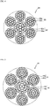
- FIG. 1 is a cross-sectional view illustrating a rubber article-reinforcing steel cord according to one preferred embodiment of the present invention.
- a steel cord 1 of the present invention has a multi-twisted structure in which plural sheath strands 3 each formed by twisting together plural filaments are twisted together around at least one core strand 2 formed by twisting together plural filaments.
- the core strand 2 and the sheath strands 3 are each formed by twisting together one or two core filaments and plural sheath filaments.
- the illustrated steel cord 1 has a (2+8)+6 ⁇ (2+8) structure in which six sheath strands 3 are twisted together around a single core strand 2, and the core strand 2 and the sheath strands 3 are each composed of a core in which two core filaments 2c or 3c are parallelly aligned without being twisted together, and eight sheath filaments 2s or 3s that are twisted together around the core.
- each core of the core strand 2 and the sheath strands 3 is constituted by one or two core filaments is because, when the core is constituted by three or more core filaments, corrosion resistance cannot be obtained in some cases since gaps into which a rubber does not infiltrate are formed inside the core.
- a relationship represented by the following Formula (1) is satisfied when a wire diameter of the core filaments 2c of the core strand 2, a wire diameter of the sheath filaments 2s of the core strand 2, a wire diameter of the core filaments 3c of the sheath strands 3, and a wire diameter of the sheath filaments 3s of the sheath strands 3 are defined as dcc, dcs, dsc and dss, respectively: dcc > dcs ⁇ dsc > dss
- the rubber penetration is improved by reducing the diameter of the filaments constituting the steel cord 1 toward the cord radial-direction outer side.
- a relationship represented by the following Formula (3) (wherein, a wire diameter of a first sheath filament of the core strand is dcs1, a wire diameter of a second sheath filament of the core strand is dcs2, a wire diameter of a first sheath filament of the sheath strands is dss1, and a wire diameter of a second sheath filament of the sheath strands is dss2) is satisfied: dcc > dcs 1 > dcs 2 ⁇ dsc > dss 1 > dss 2
- the dcs2 or the dss2 of the stand having a single sheath filament layer can be excluded from the above-described Formula (3).
- a relationship represented by the following Formula (2) be satisfied when a tensile strength of the core filaments 2c of the core strand 2, a tensile strength of the sheath filaments 2s of the core strand 2, a tensile strength of the core filaments 3c of the sheath strands 3, and a tensile strength of the sheath filaments 3s of the sheath strands 3 are defined as Tcc, Tcs, Tsc and Tss, respectively: Tss > Tsc ⁇ Tcs > Tcc
- the tensile strength T of the filaments constituting the steel cord 1 increases toward the cord radial-direction outer side.
- a bending input is applied to the steel cord 1
- a larger input is added to a filament positioned on the cord radial-direction outer side. Therefore, in the steel cord 1 of the present invention, the fatigue durability is improved by increasing the tensile strength T of the filaments constituting the steel cord 1 toward the cord radial-direction outer side.
- the steel filaments have a tensile strength T (MPa) satisfying a relationship represented by the following formula: ⁇ 2,000 ⁇ d + 3,825 ⁇ Ts ⁇ ⁇ 2,000 ⁇ d + 4,525 .
- the filaments preferably have a diameter (d) in a range of 0.3 to 0.8 mm.
- an average gap Gc between adjacent sheath filaments 2s in the same sheath filament layer of the core strand 2 be 35 to 76 ⁇ m, and that an average gap Gs between adjacent sheath filaments 3s in the same sheath filament layer of the sheath strands 3 be 20 to 76 ⁇ m.
- the average gaps Gc and Gs between the sheath filaments 2s and 3s, respectively, are smaller than the above-described respective ranges, a rubber is unlikely to infiltrate into the steel cord 1, which is not preferred.
- the core filaments 2c and 3c of the core strand 2 and the sheath strands 3 be not twisted, and the core strand 2 and the sheath strands 3 have a short axis/long axis ratio of 0.7 to 0.85 in a cross-sectional view taken along a direction perpendicular to the longitudinal direction of the strands.
- the cross-sections of the strands are flattened in the direction perpendicular to the longitudinal direction.
- the short axis/long axis ratio is lower than 0.7, since the gaps Gc and Gs between sheath filaments in the same sheath filament layer are reduced, the rubber penetration is deteriorated. Meanwhile, when the short axis/long axis ratio is higher than 0.85, since the cross-sections of the strands in the direction perpendicular to the longitudinal direction are close to being circular, the cord diameter is increased, which is disadvantageous in terms of lightweightness.
- the diameter (dcs) of the sheath filaments be smaller in the sheath filament layers on the strand radial-direction outer side.
- the rubber penetration is improved and, therefore, the effects of the present invention can be favorably attained.
- the diameter (dss) of the sheath filaments 3s be smaller in the sheath filament layers on the strand radial-direction outer side.
- an average gap between adjacent sheath filaments of a sheath filament layer on the strand radial-direction outer side be larger than an average gap between adjacent sheath filaments of a sheath filament layer on the strand radial-direction inner side.
- a ratio between a long axis of the sheath strands 3 and that of the core strand 2 be 100:105 to 130.
- this ratio is lower than 105, the core strand 2 and the sheath strands 3 have substantially the same diameter; therefore, the gaps between the sheath strands 3 in the same sheath strand layer are reduced, resulting in deterioration of the rubber penetration.
- the ratio is higher than 130, the cord diameter must be increased in order to obtain the required strength, and this leads to an increase in the gauge thickness of a coating rubber, which is disadvantageous in terms of lightweightness.
- the steel cord 1 of the present invention have a short axis/long axis ratio of 0.80 to 0.95 in a cross-sectional view taken along a direction perpendicular to the longitudinal direction of the steel cord.
- this ratio is lower than 0.80, the steel cord 1 is overly flat; therefore, the gaps between the sheath strands 3 in the same sheath strand layer are reduced, resulting in deterioration of the rubber penetration.
- the ratio is higher than 0.95, since the steel cord 1 is close to being circular, the gauge thickness of a coating rubber is increased, which is disadvantageous in terms of lightweightness.
- the steel cord 1 of the present invention it is preferred that brass plating and zinc plating be sequentially performed on the filaments.
- This constitution allows the zinc plating to corrode preferentially to the filaments and, therefore, corrosion of the filaments can be delayed.
- the zinc plating does not hinder the adhesion with a rubber.
- the zinc plating step is preferably performed by electroplating.
- molten zinc plating that is common zinc plating, since a plating treatment is performed by immersing filaments in molten zinc at 450°C or higher, the strength of the filaments is greatly reduced when the filaments have a strength of 2,500 MPa or higher. Therefore, in the production method of the present invention, this problem can be avoided by performing the zinc plating step by electroplating.
- an amount (g/m 2 ) of the brass plating adhered to the steel filaments be 6d to 10d, and an amount (g/m 2 ) of the zinc plating adhered to the steel filaments be 25d to 95d.
- the amount of the adhered brass plating is less than 6d, the drawability is deteriorated, which is not preferred. Meanwhile, when this amount is greater than 10d, the productivity is reduced, which is disadvantageous and thus not preferred from the standpoint of economic efficiency.
- the amount of the adhered zinc plating is less than 25d, the corrosion resistance may be deteriorated, which is not preferred, while an amount of greater than 95d is also not preferred since the productivity is reduced, which is disadvantageous from the standpoint of economic efficiency.
- Means for performing brass plating on a steel wire material is not particularly restricted, and a brass-plated layer may be formed by sequentially plating copper and zinc and subsequently performing a thermal diffusion treatment, or by simultaneously plating copper and zinc.
- FIGs. 2 to 5 each show a cross-sectional view of a rubber article-reinforcing steel cord according to other preferred embodiment of the present invention.
- a steel cord 11 illustrated in FIG. 2 has a structure in which six sheath strands 13 are wound on a single core strand 12, and the core strand 12 and the sheath strands 13 are each formed by twisting together six sheath filaments 12s or 13s around a single core filament 12c or 13c.
- a steel cord 21 illustrated in FIG. 3 has a structure in which six sheath strands 23 are wound on a single core strand 22, and the core strand 22 and the sheath strands 23 are each formed by twisting together eight sheath filaments 22s or 23s around a core in which two core filaments 22c or 23c are twisted together.
- a steel cord 41 illustrated in FIG. 1 A steel cord 41 illustrated in FIG.
- sheath strands 43 have a structure in which six sheath strands 43 are wound on a single core strand 42, and the core strand 42 and the sheath strands 43 are each formed by twisting together eight sheath filaments 42s or 43s around a core in which two core filaments 42c or 43c are twisted together, and further twisting together fourteen sheath filaments 42s or 43s thereon.
- the twist pitch and the twist direction of the core filaments and the sheath filaments that constitute the respective strands can be selected as appropriate in accordance with a conventional method. Further, the twist direction, the twist pitch and the like of the strands are also not particularly restricted and can be selected as appropriate in accordance with a conventional method.
- any conventionally used filaments can be selected; however, the filaments are preferably made of a high-carbon steel containing not less than 0.80% by mass of a carbon component.
- a high-hardness and high-carbon steel containing not less than 0.80% by mass of a carbon component as the material of the filaments, an effect of reinforcing a rubber article, such as a tire or a conveyer belt, can be sufficiently obtained.
- a carbon component content of higher than 1.5% is not preferred since it reduces the ductility and the fatigue resistance is thereby deteriorated.
- the use of the steel cord 1 of the present invention is not particularly restricted, and the steel cord 1 of the present invention can be widely used in a variety of rubber products and components, for example, automobile tires and industrial belts such as dynamic transmission belts and conveyor belts, as well as rubber crawlers, hoses, and seismic isolation rubber bearings. Thereamong, the steel cord 1 of the present invention can be particularly suitably used as a reinforcing material of a conveyor belt that is likely to sustain a cut damage.
- Steel cords having the respective structures shown in Tables 1 to 4 were produced.
- a steel wire material one having a wire diameter of 1.86 to 2.62 mm that was obtained by drawing and patenting a piano wire rod having a diameter of 5.5 mm and a carbon content of 0.82% by mass was used.
- This steel wire material was drawn again to obtain filaments having various wire diameters. Thereafter, the thus obtained filaments were twisted together to form strands, and these strands were plated with zinc by electroplating and further twisted together to obtain a steel cord.
- the steel wire material was patented and then plated with copper and zinc, followed by thermal diffusion and brass plating, after which the steel wire material was drawn again to obtain filaments having prescribed wire diameters. The thus obtained filaments were subsequently twisted together to form strands, and these strands were plated with zinc by electroplating and further twisted together to obtain a steel cord.
- the rubber penetration, the corrosion resistance, the cord weight, and the resistance to repeated bending fatigue were evaluated.
- the rubber penetration, the corrosion resistance, the cord weight, and the resistance to repeated bending fatigue were tested by the below-described methods.
- the steel cords were each embedded in an unvulcanized rubber and subsequently vulcanized at 145°C for 45 minutes to prepare an evaluation sample, and the state of rubber infiltration was evaluated by observing a cross-section of the steel cord in the sample.
- An evaluation of " o” was given when the rubber infiltrated into the central part of the core strand, while an evaluation of " ⁇ ” was given when the rubber did not infiltrate into the central part of the core strand.
- Tables 1 to 4 The results thereof are also shown in Tables 1 to 4.
- the steel cords were each arranged in parallel to one another at intervals of 2.0 mm and subsequently coated with a rubber sheet from both above and below, and the resultant was vulcanized at 145°C for 40 minutes to prepare an evaluation sample. From the thus obtained sample, a steel cord cut at a length of 200 mm was taken out and then immersed in a neutral aqueous solution containing nitrate ions and sulfate ions in small amounts. A bending stress of 300 N/mm 2 was repeatedly applied to the steel cord at a rate of 1,000 rotations/minute, and the number of rotations required for breaking the steel cord was measured. The number of rotations was measured up to 1,000,000. The thus obtained results were indicated as indices, taking the value measured for the steel cord of Example 1 as 100. The results thereof are also shown in Tables 1 to 4.
- the steel cords were each arranged in parallel to one another at intervals of 2.0 mm and subsequently coated with a rubber sheet from both above and below, and the resultant was vulcanized at 145°C for 40 minutes.
- a fatigue test where the sample was passed through a pulley of 50 mm in diameter and driven vertically with a tension of 8.0% of the cord strength being applied was conducted, and the number of the repeated vertical movements required for breaking the sample was measured and indicated as an index, taking the value measured for the steel cord of Example 1 as 100. The results thereof are also shown in Tables 1 to 4.
- Example 3 since the stands were not bilayer twisted cords but were three-layer twisted cords, the cord strength was higher and the cord diameter and the cord weight were larger as compared to Example 1.
Landscapes
- Chemical & Material Sciences (AREA)
- Engineering & Computer Science (AREA)
- Chemical Kinetics & Catalysis (AREA)
- Electrochemistry (AREA)
- Materials Engineering (AREA)
- Metallurgy (AREA)
- Organic Chemistry (AREA)
- Ropes Or Cables (AREA)
- Tires In General (AREA)
Abstract
Description
- The present invention relates to a rubber article-reinforcing steel cord (hereinafter, also simply referred to as "steel cord"), more particularly a rubber article-reinforcing steel cord in which the corrosion resistance is improved without an increase in weight.
- In rubber articles such as conveyor belts and tires, steel cords obtained by twisting together plural steel filaments (hereinafter, also simply referred to as "filaments") are generally used as reinforcing materials. Many proposals have been made on such steel cords.
- For example,
Patent Document 1 proposes a steel cord having a multi-twisted structure in which two core filaments are used in a core strand and the diameter of outermost-layer sheath filaments of each sheath strand is controlled to be larger than the diameter of a filament inside the outermost-layer sheaths of the sheath strand, whereby the cut resistance is improved while avoiding an increase in the diameter and the weight of the steel cord. In addition,Patent Document 2 proposes a steel cord having a multi-twisted structure in which a ratio (dc/ds) between the diameter (dc) of sheath filaments of a core strand and the diameter (ds) of outermost-layer sheath filaments of sheath strands is controlled to be higher than 1.25 but 1.50 or lower, whereby the cut resistance is improved while maintaining the amount of steel. Further,Patent Document 3 proposes a steel cord having a multi-twisted structure in which plural strands each having a layer-twisted structure composed of a core formed by two or three core filaments and at least one sheath layer are twisted together, wherein gaps between filaments constituting the outermost-layer sheaths of the strands are controlled to be 0.5 to 4.0% of the diameter of outermost-layer sheath filaments 13 and the occurrence of premature breakage of an outermost layer filament is thereby inhibited. - Still further, Patent Document 4 proposes a steel cord composed of a single core strand having a layer-twisted structure and plural sheath strands each having a layer-twisted structure, in which the average size of gaps between outermost-layer sheath filaments of the core strand is controlled to be 0.073 to 0.130 mm and the number of the outermost-layer sheath filaments is set at 7 to 10, whereby the rust resistance, the cord strength and the shear resistance are improved. Moreover, Patent Document 5 proposes a steel cord having a (2+M+N) structure in which filaments having a prescribed wire diameter are used in each layer and twisted together at a prescribed twist pitch and the amount of a filling rubber is controlled at a prescribed level, whereby the productivity and the fatigue-corrosion resistance are improved. Furthermore, Patent Document 6 proposes a steel cord obtained by twisting together plural strands each having outermost layer filaments and inner filaments, in which the adhesion with rubber is improved by performing a brass plating treatment on the outermost layer filaments of each outermost layer strand constituting an outer circumferential part and performing a zinc plating treatment on at least one filament positioned on the inner side than the outermost layer strand.
-
- [Patent Document 1]
JP 2016-69774 A - [Patent Document 2]
JP 2016-30863 A - [Patent Document 3]
JP 2009-108460 A - [Patent Document 4]
WO 2016/017654 - [Patent Document 5]
WO 2011/000950 - [Patent Document 6]
JP 2011-202291 A - Steel cords for conveyor belts are usually plated with zinc. The reason for this is because, even when rainwater or the like reached filaments through a cut or the like generated on a conveyor belt by an article being conveyed, corrosion of the filaments can be delayed by allowing the plated zinc to corrode preferentially to the filaments. However, even without such zinc plating, water does not reach the filaments in the first place as long as a rubber has infiltrated to the interior of the steel cord (this property is hereinafter also referred to as "rubber penetration"), which is preferred in terms of corrosion resistance.
- However, the easiness of a rubber to infiltrate into the interior of the steel cord means that the steel cord has large gaps therein and, in this case, the occupancy of the filaments with respect to the cord circumscribed circle is reduced, resulting in a corresponding reduction in the strength. Accordingly, the filament diameter is increased in order to ensure the strength; however, this leads to deterioration of the rubber penetration and an increase in the cord weight. Conventionally, these problems have not been sufficiently examined for steel cords having a multi-twisted structure, and there is still room for further improvement.
- In view of the above, an object of the present invention is to provide a rubber article-reinforcing steel cord in which the corrosion resistance is improved without an increase in weight.
- The present inventor intensively studied to solve the above-described problems and consequently discovered that the problems can be solved by controlling the diameters of filaments constituting a steel cord having a multi-twisted structure to satisfy a prescribed relationship, thereby completing the present invention.
- That is, the rubber article-reinforcing steel cord according to the present invention is a rubber article-reinforcing steel cord in which plural sheath strands each formed by twisting together plural steel filaments are twisted together around at least one core strand formed by twisting together plural steel filaments,
the rubber-article-reinforcing cord being characterized in that
the core strand and the sheath strands are each formed by twisting together one or two core filaments and plural sheath filaments, and
a relationship represented by the following Formula (1) is satisfied when a wire diameter of the core filament(s) of the core strand, a wire diameter of the sheath filaments of the core strand, a wire diameter of the core filaments of the sheath strands, and a wire diameter of the sheath filaments of the sheath strands are defined as dcc, dcs, dsc and dss, respectively:
- In the steel cord of the present invention, it is preferred that a relationship represented by the following Formula (2) be satisfied when a tensile strength of the core filament(s) of the core strand, a tensile strength of the sheath filaments of the core strand, a tensile strength of the core filaments of the sheath strands, and a tensile strength of the sheath filaments of the sheath strands are defined as Tcc, Tcs, Tsc and Tss, respectively:

- In the steel cord of the present invention, it is also preferred that the steel filaments have a tensile strength T (MPa) satisfying a relationship represented by the following formula:

- Further, in the steel cord of the present invention, it is preferred that the steel filaments have a diameter (d) of 0.3 to 0.8 mm. Yet still further, in the steel cord of the present invention, it is preferred that an average gap between adjacent sheath filaments in the same sheath filament layer of the core strand be 35 to 76 µm, and that an average gap between adjacent sheath filaments in the same sheath filament layer of the sheath strands be 20 to 76 µm.
- Yet still further, in the steel cord of the present invention, it is preferred that the core filaments of the core strand and the sheath strands be not twisted, and that the core strand and the sheath strands have a short axis/long axis ratio of 0.7 to 0.85 in a cross-sectional view taken along a direction perpendicular to the longitudinal direction of the strands. Yet still further, in the steel cord of the present invention, the core strand and the sheath strands have a (2+m) structure or a (2+m+n) structure, and these strands can be suitably applied to a steel cord wherein m = 8 to 9 and n = 14 to 15. Yet still further, in the steel cord of the present invention, it is preferred that, when the core strand includes two or more sheath filament layers, the diameter (dcs) of the sheath filaments be smaller in the sheath filament layers on the strand radial-direction outer side, and that, when the sheath strands each include two or more sheath filament layers, the diameter (dss) of the sheath filaments be smaller in the sheath filament layers on the strand radial-direction outer side.
- Yet still further, in the steel cord of the present invention, it is preferred that, when the core strand and the sheath strands each include two or more sheath filament layers, an average gap between adjacent sheath filaments of a sheath filament layer on the strand radial-direction outer side be larger than an average gap between adjacent sheath filaments of a sheath filament layer on the strand radial-direction inner side. Yet still further, in the steel cord of the present invention, it is preferred that a ratio between a long axis of the sheath strands and that of the core strand (long axis of sheath strands: long axis of core strand) be 100:105 to 130. Yet still further, it is preferred that the steel cord of the present invention have a short axis/long axis ratio of 0.80 to 0.95 in a cross-sectional view taken along a direction perpendicular to the longitudinal direction of the steel cord.
- Yet still further, in the steel cord of the present invention, it is preferred that brass plating and zinc plating be sequentially performed on the steel filaments. Yet still further, in the steel cord of the present invention, it is preferred that, when the diameter of the steel filaments is defined as d, an amount (g/m2) of the brass plating adhered to the steel filaments be 6d to 10d, and an amount (g/m2) of the zinc plating adhered to the steel filaments be 25d to 95d. The steel cord of the present invention can be suitably used for reinforcing a conveyor.
- According to the present invention, a rubber article-reinforcing steel cord in which the corrosion resistance is improved without an increase in weight can be provided.
-
- [
FIG. 1] FIG. 1 is a cross-sectional view illustrating a rubber article-reinforcing steel cord according to one preferred embodiment of the present invention. - [
FIG. 2] FIG. 2 is a cross-sectional view illustrating a rubber article-reinforcing steel cord according to another preferred embodiment of the present invention. - [
FIG. 3] FIG. 3 is a cross-sectional view illustrating a rubber article-reinforcing steel cord according to yet another preferred embodiment of the present invention. - [
FIG. 4] FIG. 4 is a cross-sectional view illustrating a rubber article-reinforcing steel cord according to yet another preferred embodiment of the present invention. - [
FIG. 5] FIG. 5 is a cross-sectional view illustrating a rubber article-reinforcing steel cord according to yet another preferred embodiment of the present invention. - The rubber article-reinforcing steel cord of the present invention will now be described in detail referring to the drawings.
FIG. 1 is a cross-sectional view illustrating a rubber article-reinforcing steel cord according to one preferred embodiment of the present invention. Asteel cord 1 of the present invention has a multi-twisted structure in whichplural sheath strands 3 each formed by twisting together plural filaments are twisted together around at least onecore strand 2 formed by twisting together plural filaments. Thecore strand 2 and thesheath strands 3 are each formed by twisting together one or two core filaments and plural sheath filaments. The illustratedsteel cord 1 has a (2+8)+6×(2+8) structure in which sixsheath strands 3 are twisted together around asingle core strand 2, and thecore strand 2 and thesheath strands 3 are each composed of a core in which twocore filaments sheath filaments - In the
steel cord 1 of the present invention, the reason why each core of thecore strand 2 and thesheath strands 3 is constituted by one or two core filaments is because, when the core is constituted by three or more core filaments, corrosion resistance cannot be obtained in some cases since gaps into which a rubber does not infiltrate are formed inside the core. - In the
steel cord 1 of the present invention, a relationship represented by the following Formula (1) is satisfied when a wire diameter of thecore filaments 2c of thecore strand 2, a wire diameter of thesheath filaments 2s of thecore strand 2, a wire diameter of thecore filaments 3c of thesheath strands 3, and a wire diameter of thesheath filaments 3s of thesheath strands 3 are defined as dcc, dcs, dsc and dss, respectively:
- In other words, the rubber penetration is improved by reducing the diameter of the filaments constituting the
steel cord 1 toward the cord radial-direction outer side. - In the steel cord of the present invention, when the core strand and the sheath strands each have two sheath filament layers, a relationship represented by the following Formula (3) (wherein, a wire diameter of a first sheath filament of the core strand is dcs1, a wire diameter of a second sheath filament of the core strand is dcs2, a wire diameter of a first sheath filament of the sheath strands is dss1, and a wire diameter of a second sheath filament of the sheath strands is dss2) is satisfied:

- When either the core strand or each sheath strand has two sheath filament layers, the dcs2 or the dss2 of the stand having a single sheath filament layer can be excluded from the above-described Formula (3).
- In the
steel cord 1 of the present invention, it is preferred that a relationship represented by the following Formula (2) be satisfied when a tensile strength of thecore filaments 2c of thecore strand 2, a tensile strength of thesheath filaments 2s of thecore strand 2, a tensile strength of thecore filaments 3c of thesheath strands 3, and a tensile strength of thesheath filaments 3s of thesheath strands 3 are defined as Tcc, Tcs, Tsc and Tss, respectively:
- In other words, the tensile strength T of the filaments constituting the
steel cord 1 increases toward the cord radial-direction outer side. When a bending input is applied to thesteel cord 1, a larger input is added to a filament positioned on the cord radial-direction outer side. Therefore, in thesteel cord 1 of the present invention, the fatigue durability is improved by increasing the tensile strength T of the filaments constituting thesteel cord 1 toward the cord radial-direction outer side. - In the
steel cord 1 of the present invention, it is preferred that the steel filaments have a tensile strength T (MPa) satisfying a relationship represented by the following formula:
- By controlling the tensile strength T to be (-2,000 × d + 3,825) or higher, a weight reduction effect can be obtained and, since such a tensile strength T allows the use of fine filaments, the resistance to repeated bending fatigue is improved. On the other hand, a tensile strength T of (-2,000 × d + 4,525) or higher may impair the drawability and thus present a problem in terms of the filament productivity. In the
steel cord 1 of the present invention, the filaments preferably have a diameter (d) in a range of 0.3 to 0.8 mm. The reason for this is because, when the diameter (d) of the filaments is less than 0.3 mm, the required strength cannot be attained in some cases, whereas when the diameter (d) is greater than 0.8 mm, the required tensile strength cannot be attained in some cases. - In the
steel cord 1 of the present invention, it is preferred that an average gap Gc betweenadjacent sheath filaments 2s in the same sheath filament layer of thecore strand 2 be 35 to 76 µm, and that an average gap Gs betweenadjacent sheath filaments 3s in the same sheath filament layer of thesheath strands 3 be 20 to 76 µm. When the average gaps Gc and Gs between thesheath filaments steel cord 1, which is not preferred. Meanwhile, when the average gaps Gc and Gs between thesheath filaments - Further, in the
steel cord 1 of the present invention, it is preferred that, as illustrated inFIG. 1 , thecore filaments core strand 2 and thesheath strands 3 be not twisted, and thecore strand 2 and thesheath strands 3 have a short axis/long axis ratio of 0.7 to 0.85 in a cross-sectional view taken along a direction perpendicular to the longitudinal direction of the strands. In other words, the cross-sections of the strands are flattened in the direction perpendicular to the longitudinal direction. When the short axis/long axis ratio is lower than 0.7, since the gaps Gc and Gs between sheath filaments in the same sheath filament layer are reduced, the rubber penetration is deteriorated. Meanwhile, when the short axis/long axis ratio is higher than 0.85, since the cross-sections of the strands in the direction perpendicular to the longitudinal direction are close to being circular, the cord diameter is increased, which is disadvantageous in terms of lightweightness. - Still further, in the
steel cord 1 of the present invention, it is preferred that, when thecore strand 2 has two or more sheath filament layers, the diameter (dcs) of the sheath filaments be smaller in the sheath filament layers on the strand radial-direction outer side. By adopting this constitution, the rubber penetration is improved and, therefore, the effects of the present invention can be favorably attained. Similarly, it is preferred that, when thesheath strands 3 each have two or more sheath filament layers, the diameter (dss) of thesheath filaments 3s be smaller in the sheath filament layers on the strand radial-direction outer side. - Yet still further, in the
steel cord 1 of the present invention, it is preferred that, when the core strand and the sheath strands each have two or more sheath filament layers, an average gap between adjacent sheath filaments of a sheath filament layer on the strand radial-direction outer side be larger than an average gap between adjacent sheath filaments of a sheath filament layer on the strand radial-direction inner side. Likewise as described above, by adopting this constitution, the rubber penetration is improved and, therefore, the effects of the present invention can be favorably attained. - Moreover, in the
steel cord 1 of the present invention, it is preferred that, as illustrated inFIG. 1 , a ratio between a long axis of thesheath strands 3 and that of the core strand 2 (long axis of sheath strands 3:long axis of core strand 2) be 100:105 to 130. When this ratio is lower than 105, thecore strand 2 and thesheath strands 3 have substantially the same diameter; therefore, the gaps between thesheath strands 3 in the same sheath strand layer are reduced, resulting in deterioration of the rubber penetration. Meanwhile, when the ratio is higher than 130, the cord diameter must be increased in order to obtain the required strength, and this leads to an increase in the gauge thickness of a coating rubber, which is disadvantageous in terms of lightweightness. - Furthermore, it is preferred that, as illustrated in
FIG. 1 , thesteel cord 1 of the present invention have a short axis/long axis ratio of 0.80 to 0.95 in a cross-sectional view taken along a direction perpendicular to the longitudinal direction of the steel cord. When this ratio is lower than 0.80, thesteel cord 1 is overly flat; therefore, the gaps between thesheath strands 3 in the same sheath strand layer are reduced, resulting in deterioration of the rubber penetration. Meanwhile, when the ratio is higher than 0.95, since thesteel cord 1 is close to being circular, the gauge thickness of a coating rubber is increased, which is disadvantageous in terms of lightweightness. - In the
steel cord 1 of the present invention, it is preferred that brass plating and zinc plating be sequentially performed on the filaments. This constitution allows the zinc plating to corrode preferentially to the filaments and, therefore, corrosion of the filaments can be delayed. In addition, the zinc plating does not hinder the adhesion with a rubber. For the production of such filaments, it is preferred to draw a brass-plated steel wire material into filaments and subsequently perform zinc plating thereon. The reason for this is because, when a zinc-plated steel wire material is drawn, for example, detachment of the plated zinc and abrasion of a die occur, and the productivity is thereby deteriorated. Accordingly, by performing zinc plating after the drawing step, a reduction in the drawing rate of the steel wire material is inhibited, whereby problems such as detachment of plating and abrasion of a die can be avoided. Particularly, by incorporating the zinc plating step of performing zinc plating before or after the strand twisting step, plural filaments can be simultaneously plated with zinc, which is preferred. - The zinc plating step is preferably performed by electroplating. In molten zinc plating that is common zinc plating, since a plating treatment is performed by immersing filaments in molten zinc at 450°C or higher, the strength of the filaments is greatly reduced when the filaments have a strength of 2,500 MPa or higher. Therefore, in the production method of the present invention, this problem can be avoided by performing the zinc plating step by electroplating.
- In the
steel cord 1 of the present invention, it is preferred that, when a diameter of the steel filaments is defined as d, an amount (g/m2) of the brass plating adhered to the steel filaments be 6d to 10d, and an amount (g/m2) of the zinc plating adhered to the steel filaments be 25d to 95d. When the amount of the adhered brass plating is less than 6d, the drawability is deteriorated, which is not preferred. Meanwhile, when this amount is greater than 10d, the productivity is reduced, which is disadvantageous and thus not preferred from the standpoint of economic efficiency. Further, when the amount of the adhered zinc plating is less than 25d, the corrosion resistance may be deteriorated, which is not preferred, while an amount of greater than 95d is also not preferred since the productivity is reduced, which is disadvantageous from the standpoint of economic efficiency. - Means for performing brass plating on a steel wire material is not particularly restricted, and a brass-plated layer may be formed by sequentially plating copper and zinc and subsequently performing a thermal diffusion treatment, or by simultaneously plating copper and zinc.
- In the
steel cord 1 of the present invention, as long as the above-described constitutions are satisfied, other constitutions are not particularly restricted.FIGs. 2 to 5 each show a cross-sectional view of a rubber article-reinforcing steel cord according to other preferred embodiment of the present invention. - A
steel cord 11 illustrated inFIG. 2 has a structure in which sixsheath strands 13 are wound on asingle core strand 12, and thecore strand 12 and thesheath strands 13 are each formed by twisting together sixsheath filaments single core filament steel cord 21 illustrated inFIG. 3 has a structure in which sixsheath strands 23 are wound on asingle core strand 22, and thecore strand 22 and thesheath strands 23 are each formed by twisting together eightsheath filaments core filaments steel cord 31 illustrated inFIG. 4 has a structure in which sixsheath strands 33 are wound on asingle core strand 32, and thecore strand 32 and thesheath strands 33 are each formed by twisting together sixsheath filaments single core filament sheath filaments steel cord 41 illustrated inFIG. 5 has a structure in which sixsheath strands 43 are wound on asingle core strand 42, and thecore strand 42 and thesheath strands 43 are each formed by twisting together eightsheath filaments core filaments sheath filaments - In the steel cord of the present invention, a (2+m) structure or a (2+m+n) structure wherein m = 8 to 9 and n = 14 to 15, which is capable of favorably yielding the effects of the present invention, is preferred. In the steel cord of the present invention, the twist pitch and the twist direction of the core filaments and the sheath filaments that constitute the respective strands can be selected as appropriate in accordance with a conventional method. Further, the twist direction, the twist pitch and the like of the strands are also not particularly restricted and can be selected as appropriate in accordance with a conventional method.
- As the filaments used in the
steel cord 1 of the present invention, any conventionally used filaments can be selected; however, the filaments are preferably made of a high-carbon steel containing not less than 0.80% by mass of a carbon component. By using a high-hardness and high-carbon steel containing not less than 0.80% by mass of a carbon component as the material of the filaments, an effect of reinforcing a rubber article, such as a tire or a conveyer belt, can be sufficiently obtained. Meanwhile, a carbon component content of higher than 1.5% is not preferred since it reduces the ductility and the fatigue resistance is thereby deteriorated. - The use of the
steel cord 1 of the present invention is not particularly restricted, and thesteel cord 1 of the present invention can be widely used in a variety of rubber products and components, for example, automobile tires and industrial belts such as dynamic transmission belts and conveyor belts, as well as rubber crawlers, hoses, and seismic isolation rubber bearings. Thereamong, thesteel cord 1 of the present invention can be particularly suitably used as a reinforcing material of a conveyor belt that is likely to sustain a cut damage. - The present invention will now be described in more detail by way of Examples thereof.
- Steel cords having the respective structures shown in Tables 1 to 4 were produced. As a steel wire material, one having a wire diameter of 1.86 to 2.62 mm that was obtained by drawing and patenting a piano wire rod having a diameter of 5.5 mm and a carbon content of 0.82% by mass was used. This steel wire material was drawn again to obtain filaments having various wire diameters. Thereafter, the thus obtained filaments were twisted together to form strands, and these strands were plated with zinc by electroplating and further twisted together to obtain a steel cord. In Example 4, the steel wire material was patented and then plated with copper and zinc, followed by thermal diffusion and brass plating, after which the steel wire material was drawn again to obtain filaments having prescribed wire diameters. The thus obtained filaments were subsequently twisted together to form strands, and these strands were plated with zinc by electroplating and further twisted together to obtain a steel cord.
- For each of the thus obtained steel cords, the rubber penetration, the corrosion resistance, the cord weight, and the resistance to repeated bending fatigue were evaluated. The rubber penetration, the corrosion resistance, the cord weight, and the resistance to repeated bending fatigue were tested by the below-described methods.
- The steel cords were each embedded in an unvulcanized rubber and subsequently vulcanized at 145°C for 45 minutes to prepare an evaluation sample, and the state of rubber infiltration was evaluated by observing a cross-section of the steel cord in the sample. An evaluation of " o" was given when the rubber infiltrated into the central part of the core strand, while an evaluation of "×" was given when the rubber did not infiltrate into the central part of the core strand. The results thereof are also shown in Tables 1 to 4.
- The steel cords were each arranged in parallel to one another at intervals of 2.0 mm and subsequently coated with a rubber sheet from both above and below, and the resultant was vulcanized at 145°C for 40 minutes to prepare an evaluation sample. From the thus obtained sample, a steel cord cut at a length of 200 mm was taken out and then immersed in a neutral aqueous solution containing nitrate ions and sulfate ions in small amounts. A bending stress of 300 N/mm2 was repeatedly applied to the steel cord at a rate of 1,000 rotations/minute, and the number of rotations required for breaking the steel cord was measured. The number of rotations was measured up to 1,000,000. The thus obtained results were indicated as indices, taking the value measured for the steel cord of Example 1 as 100. The results thereof are also shown in Tables 1 to 4.
- The weight per 1 m of each steel cord was measured and indicated as an index, taking that of the steel cord of Example 1 as 100. The results thereof are also shown in Tables 1 to 4.
- The steel cords were each arranged in parallel to one another at intervals of 2.0 mm and subsequently coated with a rubber sheet from both above and below, and the resultant was vulcanized at 145°C for 40 minutes. For a sample prepared by cutting out a bundle of three cords after the vulcanization, a fatigue test where the sample was passed through a pulley of 50 mm in diameter and driven vertically with a tension of 8.0% of the cord strength being applied was conducted, and the number of the repeated vertical movements required for breaking the sample was measured and indicated as an index, taking the value measured for the steel cord of Example 1 as 100. The results thereof are also shown in Tables 1 to 4.
[Table 1] Conventional Example 1 Comparative Example 1 Comparative Example 2 Comparative Example 3 Cord structure (1+6) +6×(1+6) (1+6) +6×(1+6) (2+8) +6×(2+8) (3+8) +6×(3+8) Core strand Core filament Wire diameter (mm) 0.66 0.54 0.66 0.66 Tensile strength (MPa) 2,550 2,550 2,550 2,550 Sheath filament Wire diameter (mm) 0.66 0.59 0.66 0.59 Tensile strength (MPa) 2,550 2,550 2,550 2,550 Sheath strand Core filament Wire diameter (mm) 0.66 0.59 0.66 0.59 Tensile strength (MPa) 2,550 2,550 2,550 2,550 Sheath filament Wire diameter (mm) 0.66 0.66 0.66 0.54 Tensile strength (MPa) 2,550 2,550 2,550 2,550 Gap between sheath filaments*1 (µm) Core strand 0 25 98 180 Sheath strand 0 35 98 153 Short axis/long axis of strand*2 0.99 0.98 0.95 0.99 Long axis of core strand/long axis of sheath strand × 100 100 90 100 111 Short axis/long axis of steel cord 0.99 0.96 0.97 0.99 Amount of brass plating 0 0 0 0 Amount of zinc plating 65d 65d 65d 65d Rubber penetration × × o × Corrosion resistance (index), higher is better 75 80 95 85 Cord diameter (mm), smaller is better 5.7 5.3 7.9 7.3 Cord weight (index), smaller is better 141 133 202 161 Resistance to repeated bending fatigue (index), higher is better 68 85 90 95 *1: average gap between adjacent sheath filaments
*2: (average of core strand(s) and sheath strands)[Table 2] Example 1 Example 1 2 Example 1 3 Example 1 4 Cord structure (1+6)+6×(1+6) (2+8)+6×(2+8) (2+8+14) +6×(2+8+14) (2+8)+6×(2+8) Core strand Core filament Wire diameter (mm) 0.66 0.505 0.6 0.505 Tensile strength (MPa) 2,536 3,087 2,751 3,087 Sheath filament Wire diameter (mm) 0.59 0.445 0.54/0.48 0.445 Tensile strength (MPa) 2,834 3,334 3,334/3,567 3,334 Sheath strand Core filament Wire diameter (mm) 0.59 0.445 0.48 0.445 Tensile strength (MPa) 2,834 3,334 3,186 3,334 Sheath filament Wire diameter (mm) 0.54 0.395 0.42/0.36 0.395 Tensile strength (MPa) 3,087 3,567 3,447/3,576 3,567 Gap between sheath filaments *1 (µm) Core strand 35 37 37/76 37 Sheath strand 25 31 37/73 31 Short axis/long axis of strand*2 0.96 0.80 0.78 0.80 Long axis of core strand/long axis of sheath strand × 100 110 113 129 113 Short axis/long axis of steel cord 0.95 0.87 0.85 0.87 Amount of brass plating 0 0 0 8d Amount of zinc plating 65d 65d 65d 65d Rubber penetration ○ ○ ○ ○ Corrosion resistance (index), higher is better 100 105 110 140 Cord diameter (mm), smaller is better 5.0 4.8 7.6 4.8 Cord weight (index), smaller is better 100 79 188 79 Resistance to repeated bending fatigue (index), higher is better 100 103 130 120 [Table 3] Example 5 Example 6 Example 7 Cord structure (2+8)+6×(2+8) (1+6)+6×(1+6) (2+8)+6×(2+8) Core strand Core filament Wire diameter (mm) 0.505 0.66 0.575 Tensile strength (MPa) 3,087 3,087 2,993 Sheath filament Wire diameter (mm) 0.45 0.59 0.45 Tensile strength (MPa) 3,334 2,834 3,234 Sheath strand Core filament Wire diameter (mm) 0.45 0.59 0.45 Tensile strength (MPa) 3,334 2,834 3,234 Sheath filament Wire diameter (mm) 0.395 0.54 0.395 Tensile strength (MPa) 3,567 2,536 3,567 Gap between sheath filaments *1 (µm) Core strand 34 35 77 Sheath strand 34 25 34 Short axis/long axis of strand*2 0.81 0.96 0.81 Long axis of core strand/long axis of sheath strand × 100 113 110 121 Short axis/long axis of steel cord 0.88 0.95 0.88 Amount of brass plating 0 0 0 Amount of zinc plating 65d 65d 65d Rubber penetration × o o Corrosion resistance (index), higher is better 99 100 106 Cord diameter (mm), smaller is better 4.9 5.0 5.0 Cord weight (index), smaller is better 80 100 81 Resistance to repeated bending fatigue (index), higher is better 103 95 102 [Table 4] Example 8 Example 9 Cord structure (2+8)+6×(2+8) (2+8)+6×(2+8) Core strand Core filament Wire diameter (mm) 0.505 0.55 Tensile strength (MPa) 3,087 3,322 Sheath filament Wire diameter (mm) 0.45 0.495 Tensile strength (MPa) 3,334 3,334 Sheath strand Core filament Wire diameter (mm) 0.45 0.495 Tensile strength (MPa) 3,334 3,334 Sheath filament Wire diameter (mm) 0.42 0.37 Tensile strength (MPa) 3,155 3,567 Gap between sheath filaments *1 (µm) Core strand 35 35 Sheath strand 19 77 Short axis/long axis of strand*2 0.81 0.81 Long axis of core strand/long axis of sheath strand × 100 110 121 Short axis/long axis of steel cord 0.88 0.88 Amount of brass plating 0 0 Amount of zinc plating 65d 65d Rubber penetration × o Corrosion resistance (index), higher is better 98 100 Cord diameter (mm), smaller is better 5.0 5.1 Cord weight (index), smaller is better 86 80 Resistance to repeated bending fatigue (index), higher is better 101 104 - From Tables 1 to 4, it is seen that, in the steel cords according to the present invention, the corrosion resistance was improved without an increase in the weight. It is noted here, however, that, in Example 3, since the stands were not bilayer twisted cords but were three-layer twisted cords, the cord strength was higher and the cord diameter and the cord weight were larger as compared to Example 1.
-
- 1, 11, 21, 31, 41: steel cord
- 2, 12, 22, 32, 42: core strand
- 2c, 12c, 22c, 32c, 42c: core filament
- 2s, 12s, 22s, 32s, 42s: sheath filament
- 3, 13, 23, 33, 43: sheath strand
- 3c, 13c, 23c, 33c, 43c: core filament
- 3s, 13s, 23s, 33s, 43s: sheath filament
Claims (14)
- A rubber article-reinforcing steel cord in which plural sheath strands each formed by twisting together plural steel filaments are twisted together around at least one core strand formed by twisting together plural steel filaments,
wherein
the core strand and the sheath strands are each formed by twisting together one or two core filaments and plural sheath filaments, and
a relationship represented by the following Formula (1) is satisfied when a wire diameter of the core filament(s) of the core strand, a wire diameter of the sheath filaments of the core strand, a wire diameter of the core filaments of the sheath strands, and a wire diameter of the sheath filaments of the sheath strands are defined as dcc, dcs, dsc and dss, respectively:
- The rubber article-reinforcing steel cord according to claim 1, wherein a relationship represented by the following Formula (2) is satisfied when a tensile strength of the core filament(s) of the core strand, a tensile strength of the sheath filaments of the core strand, a tensile strength of the core filaments of the sheath strands, and a tensile strength of the sheath filaments of the sheath strands are defined as Tcc, Tcs, Tsc and Tss, respectively:

- The rubber article-reinforcing steel cord according to claim 1 or 2, wherein the steel filaments have a tensile strength T (MPa) satisfying a relationship represented by the following formula:

- The rubber article-reinforcing steel cord according to any one of claims 1 to 3, wherein the steel filaments have a diameter (d) of 0.3 to 0.8 mm.
- The rubber article-reinforcing steel cord according to any one of claims 1 to 4, wherein
an average gap between adjacent sheath filaments in the same sheath filament layer of the core strand is 35 to 76 µm, and
an average gap between adjacent sheath filaments in the same sheath filament layer of the sheath strands is 20 to 76 µm. - The rubber article-reinforcing steel cord according to any one of claims 1 to 5, wherein
the core filaments of the core strand and the sheath strands are not twisted, and
the core strand and the sheath strands have a short axis/long axis ratio of 0.7 to 0.85 in a cross-sectional view taken along a direction perpendicular to the longitudinal direction of the strands. - The rubber article-reinforcing steel cord according to any one of claims 1 to 6, wherein the core strand and the sheath strands have a (2+m) structure or a (2+m+n) structure in which m = 8 to 9 and n = 14 to 15.
- The rubber article-reinforcing steel cord according to any one of claims 1 to 7, wherein
when the core strand comprises two or more sheath filament layers, the diameter (dcs) of the sheath filaments is smaller in the sheath filament layers on the strand radial-direction outer side, and
when the sheath strands each comprise two or more sheath filament layers, the diameter (dss) of the sheath filaments is smaller in the sheath filament layers on the strand radial-direction outer side. - The rubber article-reinforcing steel cord according to any one of claims 1 to 8, wherein, when the core strand and the sheath strands each comprise two or more sheath filament layers, an average gap between adjacent sheath filaments of a sheath filament layer on the strand radial-direction outer side is larger than an average gap between adjacent sheath filaments of a sheath filament layer on the strand radial-direction inner side.
- The rubber article-reinforcing steel cord according to any one of claims 1 to 9, wherein a ratio between a long axis of the sheath strands and that of the core strand (long axis of sheath strands: long axis of core strand) is 100:105 to 130.
- The rubber article-reinforcing steel cord according to any one of claims 1 to 10, having a short axis/long axis ratio of 0.80 to 0.95 in a cross-sectional view taken along a direction perpendicular to the longitudinal direction of the steel cord.
- The rubber article-reinforcing steel cord according to any one of claims 1 to 11, wherein brass plating and zinc plating are sequentially performed on the steel filaments.
- The rubber article-reinforcing steel cord according to any one of claims 1 to 12, wherein, when a diameter of the steel filaments is defined as d, an amount (g/m2) of the brass plating adhered to the steel filaments is 6d to 10d, and an amount (g/m2) of the zinc plating adhered to the steel filaments is 25d to 95d.
- The rubber article-reinforcing steel cord according to any one of claims 1 to 13, which is for a conveyor.
Applications Claiming Priority (2)
| Application Number | Priority Date | Filing Date | Title |
|---|---|---|---|
| JP2017129979A JP6936059B2 (en) | 2017-06-30 | 2017-06-30 | Steel cord for reinforcing rubber articles |
| PCT/JP2018/024702 WO2019004393A1 (en) | 2017-06-30 | 2018-06-28 | Rubber component reinforcing-steel cord |
Publications (2)
| Publication Number | Publication Date |
|---|---|
| EP3647487A1 true EP3647487A1 (en) | 2020-05-06 |
| EP3647487A4 EP3647487A4 (en) | 2021-03-03 |
Family
ID=64742388
Family Applications (1)
| Application Number | Title | Priority Date | Filing Date |
|---|---|---|---|
| EP18822739.1A Withdrawn EP3647487A4 (en) | 2017-06-30 | 2018-06-28 | Rubber component reinforcing-steel cord |
Country Status (6)
| Country | Link |
|---|---|
| US (1) | US11352744B2 (en) |
| EP (1) | EP3647487A4 (en) |
| JP (1) | JP6936059B2 (en) |
| CN (1) | CN110799699B (en) |
| AU (1) | AU2018291351B2 (en) |
| WO (1) | WO2019004393A1 (en) |
Cited By (1)
| Publication number | Priority date | Publication date | Assignee | Title |
|---|---|---|---|---|
| FR3115799A1 (en) * | 2020-11-05 | 2022-05-06 | Compagnie Generale Des Etablissements Michelin | Two-layer multi-strand cable with sheathed inner layer with improved penetrability |
Families Citing this family (4)
| Publication number | Priority date | Publication date | Assignee | Title |
|---|---|---|---|---|
| WO2020054673A1 (en) * | 2018-09-11 | 2020-03-19 | 株式会社ブリヂストン | Steel cord for reinforcing rubber article |
| FR3111921B1 (en) | 2020-06-24 | 2022-06-17 | Michelin & Cie | Two-layer multi-strand rope with improved flexural endurance |
| FR3111923B1 (en) * | 2020-06-24 | 2022-06-17 | Michelin & Cie | Two-layer multi-strand rope with improved flexural endurance |
| EP4561673A1 (en) * | 2022-07-29 | 2025-06-04 | Foundry Innovation & Research 1, Ltd. | Multistranded conductors adapted to dynamic in vivo environments |
Family Cites Families (28)
| Publication number | Priority date | Publication date | Assignee | Title |
|---|---|---|---|---|
| US4143209A (en) * | 1977-06-07 | 1979-03-06 | The Goodyear Tire & Rubber Company | Process for making zinc coated steel wire and product made thereby |
| JPS6010968B2 (en) * | 1978-09-13 | 1985-03-22 | バンドー化学株式会社 | steel cord conveyor belt |
| JPS5917234B2 (en) * | 1978-12-29 | 1984-04-20 | 横浜ゴム株式会社 | steel cord conveyor belt |
| FR2470170A1 (en) * | 1979-11-23 | 1981-05-29 | Sodetal Develop Fil Metalli | PROCESS FOR PRODUCING METALLIC WIRES FOR REINFORCING RUBBER OBJECTS |
| JPH06173179A (en) * | 1992-12-01 | 1994-06-21 | Bridgestone Corp | Steel cord for reinforcing rubber article |
| JP3486252B2 (en) * | 1995-04-11 | 2004-01-13 | 株式会社ブリヂストン | Steel cord |
| US5806296A (en) * | 1995-05-26 | 1998-09-15 | Bridgestone Metalpha Corporation | Corrosion resistant spiral steel filament and steel cord made therefrom |
| JP3096238B2 (en) * | 1996-02-15 | 2000-10-10 | 神鋼鋼線工業株式会社 | Wire rope |
| FR2798408B1 (en) * | 1999-09-15 | 2002-01-18 | Freyssinet Int Stup | PARALLEL WIRE CABLE FOR CONSTRUCTION OPENING STRUCTURE, ANCHORING SUCH CABLE, AND ANCHORING METHOD |
| US6295799B1 (en) * | 1999-09-27 | 2001-10-02 | Otis Elevator Company | Tension member for an elevator |
| WO2001086058A1 (en) * | 2000-05-08 | 2001-11-15 | N.V. Bekaert S.A. | Zinc-coated steel cord with improved fatigue resistance |
| KR100356311B1 (en) * | 2000-05-30 | 2002-10-12 | 고려제강 주식회사 | Wire cable for window regulator of automobile |
| US6817395B2 (en) * | 2002-07-30 | 2004-11-16 | The Goodyear Tire & Rubber Company | Crown reinforcement for heavy duty tires |
| JP4628239B2 (en) * | 2005-10-13 | 2011-02-09 | 株式会社ブリヂストン | Steel cords for reinforcing rubber articles and pneumatic radial tires |
| JP2009108460A (en) | 2007-10-11 | 2009-05-21 | Bridgestone Corp | Steel cord for rubber article reinforcement and pneumatic tire using the steel cord |
| JP5847990B2 (en) | 2008-11-14 | 2016-01-27 | 株式会社ブリヂストン | Steel cords for reinforcing rubber articles and pneumatic tires |
| FR2947576B1 (en) | 2009-07-03 | 2011-08-19 | Michelin Soc Tech | METAL CABLE WITH THREE LAYERS GUM IN SITU CONSTRUCTION 2 + M + N |
| US20120211310A1 (en) * | 2009-10-14 | 2012-08-23 | Danilo Peric | Elevator system and load bearing member for such a system |
| WO2011070542A1 (en) * | 2009-12-11 | 2011-06-16 | Pirelli Tyre S.P.A. | Tyre for a wheel of a heavy load vehicle |
| JP2011202291A (en) | 2010-03-24 | 2011-10-13 | Bridgestone Corp | Steel cord for reinforcing rubber body and conveyor belt |
| CN102975422B (en) * | 2012-12-12 | 2015-04-22 | 华勤钢丝绳有限公司 | High-strength steel wire, preparation method of high-strength steel wire and super-high-strength steel wire rope for conveyer belt |
| CN203373487U (en) * | 2013-07-05 | 2014-01-01 | 江苏兴达钢帘线股份有限公司 | All-steel cord for giant engineering machinery radial tire belted layer |
| JP6206168B2 (en) * | 2013-12-25 | 2017-10-04 | 横浜ゴム株式会社 | Steel cord and pneumatic radial tire using the same |
| CN103911893B (en) * | 2014-04-14 | 2017-02-15 | 江苏法尔胜技术开发中心有限公司 | Steel wire rope for conveying belt |
| JP6689747B2 (en) | 2014-07-28 | 2020-04-28 | 株式会社ブリヂストン | Steel cord for reinforcing rubber articles |
| JP6400972B2 (en) | 2014-07-28 | 2018-10-03 | 株式会社ブリヂストン | Steel cord for rubber article reinforcement |
| JP6545942B2 (en) | 2014-10-01 | 2019-07-17 | 株式会社ブリヂストン | Steel cord for reinforcing rubber articles and pneumatic tire using the same |
| JP6892374B2 (en) * | 2017-12-15 | 2021-06-23 | 株式会社ブリヂストン | Steel cords and tires for reinforcing rubber articles |
-
2017
- 2017-06-30 JP JP2017129979A patent/JP6936059B2/en active Active
-
2018
- 2018-06-28 CN CN201880042677.8A patent/CN110799699B/en active Active
- 2018-06-28 AU AU2018291351A patent/AU2018291351B2/en not_active Ceased
- 2018-06-28 EP EP18822739.1A patent/EP3647487A4/en not_active Withdrawn
- 2018-06-28 WO PCT/JP2018/024702 patent/WO2019004393A1/en not_active Ceased
-
2019
- 2019-12-27 US US16/728,125 patent/US11352744B2/en active Active
Cited By (2)
| Publication number | Priority date | Publication date | Assignee | Title |
|---|---|---|---|---|
| FR3115799A1 (en) * | 2020-11-05 | 2022-05-06 | Compagnie Generale Des Etablissements Michelin | Two-layer multi-strand cable with sheathed inner layer with improved penetrability |
| WO2022096799A1 (en) * | 2020-11-05 | 2022-05-12 | Compagnie Generale Des Etablissements Michelin | Two-layer multi-strand cord having a sheathed inner layer with improved penetrability |
Also Published As
| Publication number | Publication date |
|---|---|
| JP6936059B2 (en) | 2021-09-15 |
| WO2019004393A1 (en) | 2019-01-03 |
| US11352744B2 (en) | 2022-06-07 |
| US20200131699A1 (en) | 2020-04-30 |
| CN110799699B (en) | 2022-05-10 |
| JP2019011536A (en) | 2019-01-24 |
| CN110799699A (en) | 2020-02-14 |
| AU2018291351B2 (en) | 2021-10-21 |
| EP3647487A4 (en) | 2021-03-03 |
| AU2018291351A1 (en) | 2020-02-06 |
Similar Documents
| Publication | Publication Date | Title |
|---|---|---|
| US11352744B2 (en) | Rubber component reinforcing-steel cord | |
| EP3647488B1 (en) | Steel cord for rubber component reinforcement and production method therefor | |
| EP1280958B1 (en) | Zinc-coated steel cord with improved fatigue resistance | |
| US4854032A (en) | Method of manufacturing a steel wire with high tensile strength | |
| EP2504485B1 (en) | Open multi-strand cord | |
| KR100285075B1 (en) | Steel cord for reinforcing rubber products | |
| JPWO2009011397A1 (en) | Cord, manufacturing method thereof, and composite of cord and rubber | |
| US20130032264A1 (en) | Open off-the-road cord with preformed filaments | |
| US9951469B2 (en) | Steel cord for rubber reinforcement | |
| US5888321A (en) | Super high tensile steel wire for rubber product reinforcement, steel cord using this steel wire and radial tire using this steel cord | |
| EP2060673A1 (en) | Steel cord | |
| EP2016221B1 (en) | Metal cord and process and apparatus for manufacturing a metal cord | |
| EP3851575B1 (en) | Steel cord for reinforcing rubber article | |
| GB2252774A (en) | Reinforced transmission belt | |
| EP3710286B1 (en) | A steel cord for rubber reinforcement | |
| JPH0261184A (en) | Steel cord and tire | |
| JPH0673673A (en) | Steel cord for reinforcing rubber | |
| JPH05338752A (en) | Conveyor belt | |
| JPH0253981A (en) | Steel cord and tire | |
| JPH07229078A (en) | Metal cord and composite of this and rubber | |
| KR20090100495A (en) | Steel cord for passenger car radial tires |
Legal Events
| Date | Code | Title | Description |
|---|---|---|---|
| STAA | Information on the status of an ep patent application or granted ep patent |
Free format text: STATUS: THE INTERNATIONAL PUBLICATION HAS BEEN MADE |
|
| PUAI | Public reference made under article 153(3) epc to a published international application that has entered the european phase |
Free format text: ORIGINAL CODE: 0009012 |
|
| STAA | Information on the status of an ep patent application or granted ep patent |
Free format text: STATUS: REQUEST FOR EXAMINATION WAS MADE |
|
| 17P | Request for examination filed |
Effective date: 20200129 |
|
| AK | Designated contracting states |
Kind code of ref document: A1 Designated state(s): AL AT BE BG CH CY CZ DE DK EE ES FI FR GB GR HR HU IE IS IT LI LT LU LV MC MK MT NL NO PL PT RO RS SE SI SK SM TR |
|
| AX | Request for extension of the european patent |
Extension state: BA ME |
|
| DAV | Request for validation of the european patent (deleted) | ||
| DAX | Request for extension of the european patent (deleted) | ||
| A4 | Supplementary search report drawn up and despatched |
Effective date: 20210128 |
|
| RIC1 | Information provided on ipc code assigned before grant |
Ipc: C25D 7/06 20060101ALI20210122BHEP Ipc: D07B 1/06 20060101AFI20210122BHEP |
|
| STAA | Information on the status of an ep patent application or granted ep patent |
Free format text: STATUS: EXAMINATION IS IN PROGRESS |
|
| 17Q | First examination report despatched |
Effective date: 20221021 |
|
| STAA | Information on the status of an ep patent application or granted ep patent |
Free format text: STATUS: THE APPLICATION IS DEEMED TO BE WITHDRAWN |
|
| 18D | Application deemed to be withdrawn |
Effective date: 20230301 |