EP2016221B1 - Metal cord and process and apparatus for manufacturing a metal cord - Google Patents
Metal cord and process and apparatus for manufacturing a metal cord Download PDFInfo
- Publication number
- EP2016221B1 EP2016221B1 EP06753540.1A EP06753540A EP2016221B1 EP 2016221 B1 EP2016221 B1 EP 2016221B1 EP 06753540 A EP06753540 A EP 06753540A EP 2016221 B1 EP2016221 B1 EP 2016221B1
- Authority
- EP
- European Patent Office
- Prior art keywords
- cord
- metal
- elementary
- metal wire
- elementary metal
- Prior art date
- Legal status (The legal status is an assumption and is not a legal conclusion. Google has not performed a legal analysis and makes no representation as to the accuracy of the status listed.)
- Active
Links
- 229910052751 metal Inorganic materials 0.000 title claims description 217
- 239000002184 metal Substances 0.000 title claims description 217
- 238000004519 manufacturing process Methods 0.000 title claims description 19
- 238000000034 method Methods 0.000 title claims description 17
- 229910000831 Steel Inorganic materials 0.000 claims description 49
- 239000010959 steel Substances 0.000 claims description 49
- 239000011701 zinc Substances 0.000 claims description 9
- HCHKCACWOHOZIP-UHFFFAOYSA-N Zinc Chemical compound [Zn] HCHKCACWOHOZIP-UHFFFAOYSA-N 0.000 claims description 8
- 239000011248 coating agent Substances 0.000 claims description 7
- 238000000576 coating method Methods 0.000 claims description 7
- 238000011144 upstream manufacturing Methods 0.000 claims description 5
- 229910052725 zinc Inorganic materials 0.000 claims description 5
- 239000010941 cobalt Substances 0.000 claims description 3
- 229910001297 Zn alloy Inorganic materials 0.000 claims 3
- 229910000531 Co alloy Inorganic materials 0.000 claims 2
- 229910000914 Mn alloy Inorganic materials 0.000 claims 2
- GUTLYIVDDKVIGB-UHFFFAOYSA-N cobalt atom Chemical compound [Co] GUTLYIVDDKVIGB-UHFFFAOYSA-N 0.000 claims 1
- 230000003340 mental effect Effects 0.000 claims 1
- 239000013536 elastomeric material Substances 0.000 description 17
- 239000011295 pitch Substances 0.000 description 14
- 230000035515 penetration Effects 0.000 description 13
- LFQSCWFLJHTTHZ-UHFFFAOYSA-N Ethanol Chemical compound CCO LFQSCWFLJHTTHZ-UHFFFAOYSA-N 0.000 description 8
- 238000005260 corrosion Methods 0.000 description 7
- 230000007797 corrosion Effects 0.000 description 7
- 238000005259 measurement Methods 0.000 description 7
- 230000005540 biological transmission Effects 0.000 description 6
- 230000000052 comparative effect Effects 0.000 description 6
- 235000019441 ethanol Nutrition 0.000 description 4
- 229910001369 Brass Inorganic materials 0.000 description 3
- 239000000956 alloy Substances 0.000 description 3
- 229910045601 alloy Inorganic materials 0.000 description 3
- 239000010951 brass Substances 0.000 description 3
- 230000000694 effects Effects 0.000 description 3
- OKTJSMMVPCPJKN-UHFFFAOYSA-N Carbon Chemical compound [C] OKTJSMMVPCPJKN-UHFFFAOYSA-N 0.000 description 2
- PWHULOQIROXLJO-UHFFFAOYSA-N Manganese Chemical compound [Mn] PWHULOQIROXLJO-UHFFFAOYSA-N 0.000 description 2
- 230000015572 biosynthetic process Effects 0.000 description 2
- 229910052799 carbon Inorganic materials 0.000 description 2
- GSOLWAFGMNOBSY-UHFFFAOYSA-N cobalt Chemical compound [Co][Co][Co][Co][Co][Co][Co][Co] GSOLWAFGMNOBSY-UHFFFAOYSA-N 0.000 description 2
- 229910017052 cobalt Inorganic materials 0.000 description 2
- 229910052748 manganese Inorganic materials 0.000 description 2
- 239000011572 manganese Substances 0.000 description 2
- OCJBOOLMMGQPQU-UHFFFAOYSA-N 1,4-dichlorobenzene Chemical compound ClC1=CC=C(Cl)C=C1 OCJBOOLMMGQPQU-UHFFFAOYSA-N 0.000 description 1
- 241001589086 Bellapiscis medius Species 0.000 description 1
- 239000003795 chemical substances by application Substances 0.000 description 1
- 150000001875 compounds Chemical class 0.000 description 1
- 238000010276 construction Methods 0.000 description 1
- 230000003247 decreasing effect Effects 0.000 description 1
- 229940117389 dichlorobenzene Drugs 0.000 description 1
- 239000004744 fabric Substances 0.000 description 1
- 230000002349 favourable effect Effects 0.000 description 1
- 239000012530 fluid Substances 0.000 description 1
- 239000011521 glass Substances 0.000 description 1
- 239000000463 material Substances 0.000 description 1
- 230000000149 penetrating effect Effects 0.000 description 1
- 230000003014 reinforcing effect Effects 0.000 description 1
- 239000011435 rock Substances 0.000 description 1
- 239000002904 solvent Substances 0.000 description 1
- 239000000126 substance Substances 0.000 description 1
- 238000004073 vulcanization Methods 0.000 description 1
Images


Classifications
-
- D—TEXTILES; PAPER
- D07—ROPES; CABLES OTHER THAN ELECTRIC
- D07B—ROPES OR CABLES IN GENERAL
- D07B1/00—Constructional features of ropes or cables
- D07B1/06—Ropes or cables built-up from metal wires, e.g. of section wires around a hemp core
- D07B1/0606—Reinforcing cords for rubber or plastic articles
- D07B1/0646—Reinforcing cords for rubber or plastic articles comprising longitudinally preformed wires
-
- D—TEXTILES; PAPER
- D07—ROPES; CABLES OTHER THAN ELECTRIC
- D07B—ROPES OR CABLES IN GENERAL
- D07B7/00—Details of, or auxiliary devices incorporated in, rope- or cable-making machines; Auxiliary apparatus associated with such machines
- D07B7/02—Machine details; Auxiliary devices
- D07B7/025—Preforming the wires or strands prior to closing
-
- D—TEXTILES; PAPER
- D07—ROPES; CABLES OTHER THAN ELECTRIC
- D07B—ROPES OR CABLES IN GENERAL
- D07B2201/00—Ropes or cables
- D07B2201/20—Rope or cable components
- D07B2201/2001—Wires or filaments
- D07B2201/2007—Wires or filaments characterised by their longitudinal shape
-
- D—TEXTILES; PAPER
- D07—ROPES; CABLES OTHER THAN ELECTRIC
- D07B—ROPES OR CABLES IN GENERAL
- D07B2201/00—Ropes or cables
- D07B2201/20—Rope or cable components
- D07B2201/2001—Wires or filaments
- D07B2201/2007—Wires or filaments characterised by their longitudinal shape
- D07B2201/2008—Wires or filaments characterised by their longitudinal shape wavy or undulated
-
- D—TEXTILES; PAPER
- D07—ROPES; CABLES OTHER THAN ELECTRIC
- D07B—ROPES OR CABLES IN GENERAL
- D07B2201/00—Ropes or cables
- D07B2201/20—Rope or cable components
- D07B2201/2015—Strands
- D07B2201/2022—Strands coreless
-
- D—TEXTILES; PAPER
- D07—ROPES; CABLES OTHER THAN ELECTRIC
- D07B—ROPES OR CABLES IN GENERAL
- D07B2201/00—Ropes or cables
- D07B2201/20—Rope or cable components
- D07B2201/2015—Strands
- D07B2201/2024—Strands twisted
-
- D—TEXTILES; PAPER
- D07—ROPES; CABLES OTHER THAN ELECTRIC
- D07B—ROPES OR CABLES IN GENERAL
- D07B2201/00—Ropes or cables
- D07B2201/20—Rope or cable components
- D07B2201/2015—Strands
- D07B2201/2024—Strands twisted
- D07B2201/2029—Open winding
-
- D—TEXTILES; PAPER
- D07—ROPES; CABLES OTHER THAN ELECTRIC
- D07B—ROPES OR CABLES IN GENERAL
- D07B2201/00—Ropes or cables
- D07B2201/20—Rope or cable components
- D07B2201/2015—Strands
- D07B2201/2038—Strands characterised by the number of wires or filaments
- D07B2201/2039—Strands characterised by the number of wires or filaments three to eight wires or filaments respectively forming a single layer
-
- D—TEXTILES; PAPER
- D07—ROPES; CABLES OTHER THAN ELECTRIC
- D07B—ROPES OR CABLES IN GENERAL
- D07B2207/00—Rope or cable making machines
- D07B2207/20—Type of machine
- D07B2207/202—Double twist unwinding
-
- D—TEXTILES; PAPER
- D07—ROPES; CABLES OTHER THAN ELECTRIC
- D07B—ROPES OR CABLES IN GENERAL
- D07B2501/00—Application field
- D07B2501/20—Application field related to ropes or cables
- D07B2501/2046—Tire cords
-
- D—TEXTILES; PAPER
- D07—ROPES; CABLES OTHER THAN ELECTRIC
- D07B—ROPES OR CABLES IN GENERAL
- D07B2501/00—Application field
- D07B2501/20—Application field related to ropes or cables
- D07B2501/2076—Power transmissions
-
- Y—GENERAL TAGGING OF NEW TECHNOLOGICAL DEVELOPMENTS; GENERAL TAGGING OF CROSS-SECTIONAL TECHNOLOGIES SPANNING OVER SEVERAL SECTIONS OF THE IPC; TECHNICAL SUBJECTS COVERED BY FORMER USPC CROSS-REFERENCE ART COLLECTIONS [XRACs] AND DIGESTS
- Y10—TECHNICAL SUBJECTS COVERED BY FORMER USPC
- Y10T—TECHNICAL SUBJECTS COVERED BY FORMER US CLASSIFICATION
- Y10T428/00—Stock material or miscellaneous articles
- Y10T428/12—All metal or with adjacent metals
- Y10T428/12333—Helical or with helical component
-
- Y—GENERAL TAGGING OF NEW TECHNOLOGICAL DEVELOPMENTS; GENERAL TAGGING OF CROSS-SECTIONAL TECHNOLOGIES SPANNING OVER SEVERAL SECTIONS OF THE IPC; TECHNICAL SUBJECTS COVERED BY FORMER USPC CROSS-REFERENCE ART COLLECTIONS [XRACs] AND DIGESTS
- Y10—TECHNICAL SUBJECTS COVERED BY FORMER USPC
- Y10T—TECHNICAL SUBJECTS COVERED BY FORMER US CLASSIFICATION
- Y10T428/00—Stock material or miscellaneous articles
- Y10T428/12—All metal or with adjacent metals
- Y10T428/12424—Mass of only fibers
Definitions
- This invention relates to a metal cord and to a process for manufacturing a metal cord.
- the present invention relates to a metal cord, usually used as a reinforcing element in elastomeric manufactured articles, comprising at least one preformed elementary metal wire.
- the present invention also relates to a process for manufacturing a metal cord.
- the present invention also relates to an apparatus for manufacturing a metal cord.
- the above disclosed metal cord may be employed to produce reinforced elastomeric manufactured articles such as, for example, tires, pipes for high pressure fluids, belts, belt conveyors, and the like.
- the metal cords usually employed to reinforce elastomeric manufactured articles are generally made of several elementary metal wires twisted along an axis which coincides with the longitudinal development of the cords themselves.
- Said metal cords especially when employed in the manufacturing of tires, are generally required to be provided with high mechanical resistance and to allow a good physico-chemical adhesion with the elastomeric material in which they are embedded, as well as a good penetration of said elastomeric material in the space between the adjacent elementary metal wires of said metal cords.
- the elementary metal wires forming said metal cords are compacted, i.e. positioned intimately in contact with one another, leading to the formation of one or more closed cavities inside said metal cords which extend along the longitudinal development of the same.
- the presence of said closed cavities which cannot be reached by the elastomeric material involves a reduced adhesion of the metal wires to the elastomeric material which may cause an undesired tendency of the metal wires to separate from the same.
- the use of the so-called "open” cords has been disclosed.
- the metal wires generally from three to five
- the metal wires are loosely associated so that they are at a certain distance from one another and this distance is maintained during the entire rubberizing phase, for example, by keeping a low traction load (usually not exceeding five kilograms) applied to the cord.
- Cords of the type above disclosed namely the so-called "open" cords, are described, for example, in United States Patent US 4,258,543 in the name of the Applicant.
- the cords therein disclosed are said to allow an excellent penetration of the elastomeric material between the adjacent metal wires forming the cords.
- United States Patent US 6,698,179 in the name of the Applicant, relates to a process for manufacturing a metal cord including the steps of permanently deforming at least one wire using a substantially sinusoidal deformation lying in a plane and stranding the at least one wire together with one or more other wires by twisting the wires around a longitudinal axis of the metal cords, as well as to a metal cord so obtained.
- the abovementioned metal cord is said to have a good rubber penetration as well as an improved elongation at break.
- the tension to which they are subjected before they reach the rubberizing device may cause the compacting of the wires one against the other, thus hindering the elastomeric material from penetrating between the adjacent metal wires of the cords. Consequently, although being endowed with a high part load elongation (PLE), i.e. a high elongation to low load (lower than or equal to 50 N), said cords may not allow a good elastomeric material penetration so causing a corrosion of the metal wires, and severely compromising the structural resistance of both the cords and of the reinforced elastomeric manufactured articles containing the same.
- PLE part load elongation
- the metal cords of the prior art such as, for example, those disclosed in International Patent Applications WO 95/16816 , in WO 99/28547 , or in United States Patent US 6,698,179 above reported, although being endowed with high elongation at break as well as a good elastomeric material penetration, may show a low part load elongation (PLE).
- Said low part load elongation (PLE) may cause problems during the manufacturing of the reinforced elastomeric manufactured articles comprising the same, in particular when used in tires manufacturing where remarkable elongations of the metal cords are required during the various manufacturing steps.
- the Applicant has now found a metal cord comprising one or more elementary metal wires, provided with both a high elongation at break and a high part load elongation (PLE), said characteristics being maintained substantially unchanged even after the metal cord has been rubberized and vulcanized. Moreover, said metal cord shows an improved elastomeric material penetration between the adjacent elementary metal wires forming said metal cord.
- PLE part load elongation
- the present invention relates to a metal cord according to claim 1.
- said metal cord has at least one preformed elementary metal wire, while the remaining elementary metal wires forming said metal cord may be of the non-preformed type. Prior to undergoing a given preforming action, the elementary metal wires have a straight configuration.
- the elementary metal wire is subjected along its longitudinal development, at positions substantially regularly spaced, to a deformation by applying a transverse force above the elastic threshold of the material forming said elementary metal wire, so that the deformation remains when the applied force is removed.
- Said elementary metal wire is firstly preformed so that it assumes substantially sinusoidal undulations; secondly, said firstly preformed elementary metal wire is helicoidally preformed, along its longitudinal axis, so that it assumes a helical wave-shaped configuration (hereinafter referred also to as "double-preformed elementary metal wire").
- double-preformed elementary metal wire The result of said double preforming is an elementary metal wire tri-dimensionally preformed.
- said sinusoidal undulations have a wavelength (or pitch) of from 1.0 mm to 15 mm, more preferably of from 2.0 mm to 8.0 mm.
- said sinusoidal undulations have a wave amplitude of from 0.10 mm to 1.0 mm, more preferably of from 0.20 mm to 0.50 mm.
- the wavelength and wave amplitude ranges referred to above may be measured directly on the non-rubberized elementary metal wire before it is inserted into the elastomeric material which will be subsequently vulcanized.
- the measurement of said parameters may be performed on the elementary metal wire by using a magnifying lens and a graduated scale (for example a graduated ruler).
- a magnifying lens and a graduated scale for example a graduated ruler.
- solvents for example by treating it with dichlorobenzene, at a temperature of at least 100°C, preferably of 140°C, for at least 12 hours.
- said elementary metal wire has a diameter (D) of from 0.10 mm to 0.50 mm, preferably of from 0.12 mm to 0.40 mm.
- said elementary metal wire is made of steel.
- the breaking strength of a standard NT (normal tensile) steel ranges between about 2,600 N/mm 2 (or 2,600 MPa - MegaPascal) and about 3,200 N/mm 2
- the breaking strength of a HT (High Tensile) steel ranges between about 3,000 N/mm 2 and about 3,600 N/mm 2
- the breaking strength of a SHT (Super High Tensile) steel ranges between about 3,300 N/mm 2 and about 3,900 N/mm 2
- the breaking strength of a UHT (Ultra High Tensile) steel ranges between about 3,600 N/mm 2 and about 4,200 N/mm 2 .
- Said breaking strength values depend in particular on the quantity of carbon contained in the steel.
- the above disclosed HT, SHT and UHT elementary metal wire type are made of steel having a very high carbon content, usually greater than 0.9%).
- said elementary metal wire is provided with a brass coating (Cu of between 60% and 75% by weight, Zn of between 40% and 25% by weight), having a thickness of between 0.10 ⁇ m and 0.50 ⁇ m. Said coating ensures better adhesion of the elementary metal wire to the rubberizing compound and provides for protection against corrosion of the metal, both during production of the reinforced elastomeric manufactured articles and during use thereof.
- a brass coating Cu of between 60% and 75% by weight, Zn of between 40% and 25% by weight
- said elementary metal wire may be advantageously provided with an anti-corrosive coating other than brass, able to ensure a greater corrosion resistance, such as, for example, a coating based on zinc, zinc/manganese (ZnMn) alloys, zinc/cobalt (ZnCo) alloys or zinc/cobalt/manganese (ZnCoMn) alloys.
- an anti-corrosive coating other than brass able to ensure a greater corrosion resistance, such as, for example, a coating based on zinc, zinc/manganese (ZnMn) alloys, zinc/cobalt (ZnCo) alloys or zinc/cobalt/manganese (ZnCoMn) alloys.
- said metal cord has a structure of the type n x D, wherein n is the number of elementary metal wires forming the cord and D is the diameter of each elementary metal wire.
- n ranges of from 2 to 6. Particularly preferred is n equal to 5.
- Preferred metal cord constructions are, for example: 2x (i.e. two elementary metal wires twisted together), 3x, 4x, 5x, 6x, 2+1 (i.e. one strand of two metal wires and one strand of one metal wires, said two strands being twisted together), 2+2, 3+2, 1+4.
- said metal cord has a stranding pitch of from 2.5 mm to 25 mm, more preferably of from 6 mm to 18 mm.
- said metal cord has the following characteristics:
- Gap Area it is intended the area, in a cord cross-section, defined by segments connected together to form a polygon, each of said segments having its extremity on the outer circumferences of a couple of adjacent elementary metal wires.
- the present invention relates to a process for manufacturing a metal cord comprising the steps of:
- the preformed metal wire obtained according to step (a) and step (b) is substantially devoid of sharp edges and/or discontinuities in curvature along its longitudinal development. Said feature is particularly advantageous since, the absence of said sharp edges/corners, results in a favourable increasing of the breaking load of the elementary metal wire.
- the present invention also relates to an apparatus for manufacturing a metal cord comprising:
- apparutus may comprise at least one first preforming device for each elementary metal wire of the metal cord.
- said at least one first preforming device comprises a first and a second pulley, each pulley having a plurality of circumferentially arranged pins, said pulleys being positioned at a distance so that during rotation the pins of the first and the second pulley interpenetrate so as to induce a substantially sinusoidal deformation without sharp edges on a wire passing through the space between the pins of the first pulley and the corresponding pins of the second pulley.
- said at least one second preforming device comprises a pulley and a rotating pin, said roating pin being positioned between said pulley and the first end section of the stranding path in such a way that, the internal angle ( ⁇ ) formed by the rotating pin inlet elementary metal wire and the rotating pin outlet elementary metal wire is lower than or equal to 180°, preferably of from 45° to 90°.
- said rotating pin may have at least one groove, more preferably a plurality of parallel grooves.
- saids pulley is an adjustable pulley.
- Said appartus may comprise at least one second preforming device for each elementary metal wire.
- reference sign 1 indicates the metal cord 1.
- Said metal cord 1 comprises several elementary metal wires (not illustrated in Fig. 1 ), preferably made of steel, and more preferably provided with a brass coating, having a diameter (D) of from 0.10 mm to 0.50 mm, preferably of from 0.12 mm to 0.40 mm twisted around the longitudinal axis of the metal cord.
- Fig. 1 shows an example of an apparatus 10 for forming a metal cord 1 consisting of five elementary metal wires.
- the device 10 for the production of the metal cord 1 comprises, in a known configuration, a supporting structure 100 to which a rotor 5 is rotatively engaged, the latter being rotated by means of a motor or similar devices (not illustrated in Fig. 1 ). Furthermore, a cradle (not illustrated in Fig. 1 is connected to said supporting structure and can rock about the rotation axis of rotor 5. Several feeding spools 8 are operatively engaged on the cradle. At least one elementary metal wire of said metal cord 1 is wound on each of the feeding spools 8.
- unwinding devices (not illustrated in Fig. 1 because known per se and conventional) are coupled to feeding spools 8, which are fitted on the cradle to guide the elementary metal wires coming from the feeding spools 8.
- the elementary metal wires at the outlet from the cradle are driven onto rotor 5 according to a predefined stranding path along which the metal cord 1 is formed through the effect of rotation imposed on rotor 5 by means of said motor or equivalent device, in combination with the drive produced on the metal cord 1 by means of collection devices (not illustrated in Fig. 1 since known and not relevant to the scope of the invention).
- the stranding path comprises a first end section 10a essentially coinciding with the rotation axis of rotor 5 and delimited by a first rotating transmission device 12, solidly fastened to rotor 5, and an assembly unit 11 consisting, in a known way, of a plate with five holes, solidly fastened to the cradle and, consequently, stationary.
- the elementary metal wires are subjected to a first torsion around the rotation axis of rotor 5 through the effect of the rotating pull which the rotor imposes on the first rotating transmission device 12.
- the elementary metal wires follow a central section 10b of the stranding path which extends to rotor 5 and is radially spaced from the rotation axis of the rotor so as to skip cradle (not illustrated in Fig. 1 ) and reach a second transmission device 13 solidly fastened to the rotor 5 on the axially opposite end.
- the stranding path presents a second end section 10c substantially coinciding with the rotation axis of rotor 5 and extending beyond second rotating transmission device 13.
- this second end section through the effect of the rotating pull imposed by rotor 5 on second rotating transmission device 13, a second torsion of the elementary wires is performed, thus completing the formation of the metal cord 1 which is progressively pulled away by the aforesaid collection devices.
- the ratio between the speed of rotation of rotor 5, preferably of from 2000 rpm to 6000 rpm, and the pulling speed of metal cord 1 and, consequently, of the elementary metal wires which form it, preferably of from 60 m/min to 250 m/min defines the value of the stranding pitch, i.e. the stranding pitch according to which said elementary metal wires are twisted on finished metal cord 1.
- said stranding pitch is kept at a value of from 2.5 mm to 25 mm, preferably of from 6 mm to 18 mm.
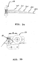
- inlet guiding pulleys 14 first preforming devices 15, outlet guiding pulley 16 consisting of a pulley turned at 90° with ) respect to the pair of pulleys of the first preforming device said turned pulley has the purpose of conveying the elementary metal wires coming out of the first preforming devices 15, to a second preforming device comprising an adjustable pulley 17 and a rotating pin 18 according to the present invention (shown in detail in Fig. 2a and in Fig. 2b ).
- Fig. 1 both at the exit of the outlet guiding pulley 16 and of the adjustable pulley 17, the five elementary metal wires coming from the first preforming device 15 and the adjustable pulley 17 respectively, are ) represented, for simplicity, by means of a single line.
- a second outlet guiding pulley may be present detween the rotating pin 18 and the assembly device 11 (not represented in Fig. 1 ).
- Fig. 2a shows a partial top view of a rotating pin 18 of the second preforming device according to the present invention comprising a.plurality of grooves.
- the reference sign 201 indicate the five elementary metal wires coming from the adjustable pulley 17.
- Said rotating pin is preferably of steel.
- Fig. 2b shows a partial top view of the second preforming device according to the present invention comprising an adjustable pulley 17 and a rotating pin 18, wherein A represents the distance between the central axis of the adjustable pulley 17 and the central axis of rotating pin 18, said distance being preferably of from 5 mm to 50 mm, d represents the diameter, in a cross-section, of the rotating pin 18, said diameter being preferably of from 1 mm to 10 mm, and ( ⁇ ) represents the internal angle formed by the rotating pin inlet elementary metal wire and the rotating pin outlet elementary metal wire. Varying both the distance A, the diameter d, and the internal angle ( ⁇ ), it is possible to obtain elementary metal wires having different pitch and wave amplitude. Also in Fig. 2b , the five elementary metal wires coming from both the outlet guiding pulley 16 (not represented in Fig. 2b ) and from the adjustable pulley 17, are represented, for simplicity, by means of a single line.
- the device 10 comprises a stretching device (capstan), a device for collecting the produced metal cord and the usual elementary metal wire straightening devices, such as the false twister, to eliminate residual tension in the finished metal cord.
- a stretching device capstan
- the usual elementary metal wire straightening devices such as the false twister
- the first and the second preforming devices according to the present invention may be applied to all types of known stranding systems, for example a double twist system or an arrangement system.
- a double twist system may present internal collection (if the collection spool of the finished product is inside of the cradle, between the rotors) or external collection (if the feeding spools are inside of the cradle while the collection spool of the finished product is outside the cradle).
- the arrangement system finally, differentiates from the double twist system as in arrangement machines each rotor turn corresponds to a single stranding pitch ) while in double twist machines each turn of the rotors corresponds to an advancement equal to two stranding pitches. Consequently, the difference between these two systems lies in their productivity.
- the elementary metal wire has, preferably, a wavelength (or pitch) of from 1.0 mm to 15 mm, more preferably of from 2.0 mm to 8.0 mm, and a wave amplitude of from 0.10 mm to 1.0 mm, more preferably of from 0.20 mm to 0.50 mm.
- Fig. 3 shows a cross-section of a metal cord of the following type 5 x 0.25 (i.e., five elementary metal wires having 0.25 mm of diameter stranded together to form a metal cord), wherein l 1 , l 2 , l 3 , l 4 and l 5 are the distance between the centres of two adjacent elementary metal wire in a cross-section, s 1 , s 2 , s 3 , s 4 and s 5 are the distance between each couple of adjacent elementary metal wires in a cross-section, 20 is the gap area.
- all the elementary metal wires have the same diameter D (not represented in Fig. 3 ).
- Fig. 4 shows a photographic top view of a particular embodiment of a metal cord according to the present invention, said metal cord comprising five double-preformed elementary metal wires.
- the breaking load, the elongation at break, and the part load elongation (PLE) at 50 N were measured both on bare steel cord and on rubberized/vulcanized cord (namely, the steel cord which was previuosly embedded in the elastomeric material and subjected to vulcanisation according to methods known in the art). Said measurements were carried out according to method BISFA as disclosed above and the obtained data were given in Table 1.
- the part load elongation (PLE) at 50 N is defined as the increase in length of the steel cord, which results from subjecting the steel cord to a defined force of 50 N and is expressed as a percentage of the initial length of the steel cord under a defined pre-tension (for example, 2.5 N).
- Example 1 shows both high elongation at break and high part load elongation (PLE) and that said characteristics are maintained even in the rubberized/vulcanized cord.
- the breaking load, the elongation at break, and the part load elongation (PLE) were measured on bare steel cord: the measurements were carried out according to method BISFA as disclosed above and the obtained data were given in Table 2.
- PLE part load elongation
- the sample to be examined consisting of a strip of the type described above with dimensions equal to 5 cm x 5 cm, was submerged in the bowl and positioned at the inlet of the funnel.
- Ethyl alcohol has the property of expelling the air which may be contained in the elastomeric material and to take its place. This fact caused a decrease with respect to the aforesaid zero level of the level of ethyl alcohol in the scaled stem.
- This measurement allowed to define the volume of air possessed by the elastomeric material in which the steel wires are embedded and, consequently, the penetration degree of the rubber between the steel wires forming the steel cord.
- EXAMPLE 5 (a) Stranding Pitch (mm) 12.5 S 12.5 S Breaking load (*) (N) 596 558 Elongation at break (*) (MPa) 4.20 4.04 Part load elongation (PLE) at 50 N (%) (**) 0.605 0.240 Rubber penetration (mm 3 /cm of cord) 0.28 0.10 (a) : comparative; (*) : method BISFA E6; (**) : method BISFA E7.
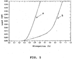
- Example 4 shows improved mechanical characteristics (in particular, a part load elongation - see also Fig. 5 ) with respect to the steel cord of the prior art (Example 5). Moreover the steel cord according to the present invention (Example 4) shows an improved rubber penetration with respect to the steel cord of the prior art (Example 5).
- each portion was subjected to five cross-sections (in particular, one stranding pitch of each portion was subjected to five cross-sections, said cross-sections having all the same length) and the above reported measurements were made for each cross-section.
- the measurements were made by using a magnifying lens and a graduated ruler: the obtained data are given in Table 3.
- the steel cord according to the present invention maintains the above reported characteristics, i.e. the gap area (G.A.) and the sum of the distance between each couple of adjacent metal wires in a cross-section ( ⁇ s n ), along its entire longitudinal development.
Description
- This invention relates to a metal cord and to a process for manufacturing a metal cord.
- More in particular, the present invention relates to a metal cord, usually used as a reinforcing element in elastomeric manufactured articles, comprising at least one preformed elementary metal wire.
- Moreover, the present invention also relates to a process for manufacturing a metal cord.
- Furthermore, the present invention also relates to an apparatus for manufacturing a metal cord.
- The above disclosed metal cord may be employed to produce reinforced elastomeric manufactured articles such as, for example, tires, pipes for high pressure fluids, belts, belt conveyors, and the like.
- As it is known, the metal cords usually employed to reinforce elastomeric manufactured articles are generally made of several elementary metal wires twisted along an axis which coincides with the longitudinal development of the cords themselves.
- Said metal cords, especially when employed in the manufacturing of tires, are generally required to be provided with high mechanical resistance and to allow a good physico-chemical adhesion with the elastomeric material in which they are embedded, as well as a good penetration of said elastomeric material in the space between the adjacent elementary metal wires of said metal cords.
- In fact, it is known that, in order to avoid the risk of the metal cords undergoing undesired corrosion phenomena once inside the reinforced elastomeric manufactured article, it is very important that the elementary metal wires forming the metal cords are entirely coated, for their entire superficial development, by said elastomeric material.
- This result, which is more difficult to be achieved when more complex metal cords are considered, is not easily achieved even when dealing with metal cords formed by a low number of elementary metal wires.
- In fact, in order to confer the required geometric and structural stability to the metal cords, the elementary metal wires forming said metal cords are compacted, i.e. positioned intimately in contact with one another, leading to the formation of one or more closed cavities inside said metal cords which extend along the longitudinal development of the same.
- These cavities are closed and, consequently, cannot be reached by the elastomeric material during the normal rubberizing phases of the metal cord and, as a consequence, corrosion may develop inside said closed cavities and propagate along the elementary metal wires forming the same.
- As a consequence, this means, for example, that owing to cuts in the reinforced elastomeric manufactured product, humidity and/or external agents may penetrate into said closed cavities inevitably starting a rapid process of corrosion of the elementary metal wires, thus severely compromising the structural resistance of the metal cords themselves and, consequently, of the reinforced elastomeric manufactured product.
- Furthermore, the presence of said closed cavities which cannot be reached by the elastomeric material involves a reduced adhesion of the metal wires to the elastomeric material which may cause an undesired tendency of the metal wires to separate from the same.
- An additional disadvantage due to insufficient rubberizing of the metal wires, caused by the presence of said closed cavities, is the development of fretting of the metal wires in contact with one another. This generates an inevitable decrease of resistance to fatigue of the metal wires and, consequently, of the metal cords.
- Attempt have been made in the art to overcome the above reported problems.
- For example, the use of the so-called "open" cords has been disclosed. In said "open"cords the metal wires (generally from three to five) are loosely associated so that they are at a certain distance from one another and this distance is maintained during the entire rubberizing phase, for example, by keeping a low traction load (usually not exceeding five kilograms) applied to the cord.
- Cords of the type above disclosed, namely the so-called "open" cords, are described, for example, in United States Patent
US 4,258,543 in the name of the Applicant. The cords therein disclosed, are said to allow an excellent penetration of the elastomeric material between the adjacent metal wires forming the cords. - International Patent Application
WO 95/16816 - International Patent Application
WO 99/28547 - United States Patent
US 6,698,179 , in the name of the Applicant, relates to a process for manufacturing a metal cord including the steps of permanently deforming at least one wire using a substantially sinusoidal deformation lying in a plane and stranding the at least one wire together with one or more other wires by twisting the wires around a longitudinal axis of the metal cords, as well as to a metal cord so obtained. The abovementioned metal cord is said to have a good rubber penetration as well as an improved elongation at break. - However, the metal cords above disclosed may show some drawbacks.
- For example, in the case of the so called "open" cords, the tension to which they are subjected before they reach the rubberizing device, may cause the compacting of the wires one against the other, thus hindering the elastomeric material from penetrating between the adjacent metal wires of the cords. Consequently, although being endowed with a high part load elongation (PLE), i.e. a high elongation to low load (lower than or equal to 50 N), said cords may not allow a good elastomeric material penetration so causing a corrosion of the metal wires, and severely compromising the structural resistance of both the cords and of the reinforced elastomeric manufactured articles containing the same.
- On the other end, the metal cords of the prior art such as, for example, those disclosed in International Patent Applications
WO 95/16816 WO 99/28547 US 6,698,179 above reported, although being endowed with high elongation at break as well as a good elastomeric material penetration, may show a low part load elongation (PLE). Said low part load elongation (PLE) may cause problems during the manufacturing of the reinforced elastomeric manufactured articles comprising the same, in particular when used in tires manufacturing where remarkable elongations of the metal cords are required during the various manufacturing steps. - Moreover, the Applicant has noticed that, after the metal cords are rubberized and vulcanized, both the elongation at break and the part load elongation (PLE) are significantly decreased.
- The Applicant has now found a metal cord comprising one or more elementary metal wires, provided with both a high elongation at break and a high part load elongation (PLE), said characteristics being maintained substantially unchanged even after the metal cord has been rubberized and vulcanized. Moreover, said metal cord shows an improved elastomeric material penetration between the adjacent elementary metal wires forming said metal cord.
- According to a first aspect, the present invention relates to a metal cord according to
claim 1. - According to the invention said metal cord has at least one preformed elementary metal wire, while the remaining elementary metal wires forming said metal cord may be of the non-preformed type. Prior to undergoing a given preforming action, the elementary metal wires have a straight configuration.
- For the aim of the present description and of the claims which follow, with the term "preformed" it is meant that the elementary metal wire is subjected along its longitudinal development, at positions substantially regularly spaced, to a deformation by applying a transverse force above the elastic threshold of the material forming said elementary metal wire, so that the deformation remains when the applied force is removed.
- Said elementary metal wire is firstly preformed so that it assumes substantially sinusoidal undulations; secondly, said firstly preformed elementary metal wire is helicoidally preformed, along its longitudinal axis, so that it assumes a helical wave-shaped configuration (hereinafter referred also to as "double-preformed elementary metal wire"). The result of said double preforming is an elementary metal wire tri-dimensionally preformed.
- According to a preferred embodiment, said sinusoidal undulations have a wavelength (or pitch) of from 1.0 mm to 15 mm, more preferably of from 2.0 mm to 8.0 mm.
- According to a further preferred embodiment, said sinusoidal undulations have a wave amplitude of from 0.10 mm to 1.0 mm, more preferably of from 0.20 mm to 0.50 mm.
- The wavelength and wave amplitude ranges referred to above may be measured directly on the non-rubberized elementary metal wire before it is inserted into the elastomeric material which will be subsequently vulcanized. Advantageously, the measurement of said parameters may be performed on the elementary metal wire by using a magnifying lens and a graduated scale (for example a graduated ruler). In the case where a vulcanized reinforced elastomeric manufactured article has to be analysed, it is necessary to remove the elastomeric material therefrom by using solvents, for example by treating it with dichlorobenzene, at a temperature of at least 100°C, preferably of 140°C, for at least 12 hours.
- According to one preferred embodiment, said elementary metal wire has a diameter (D) of from 0.10 mm to 0.50 mm, preferably of from 0.12 mm to 0.40 mm.
- According to one preferred embodiment, said elementary metal wire is made of steel. In the case where the diameter of the elementary metal wire is of from 0.10 mm to 0.50 mm, the breaking strength of a standard NT (normal tensile) steel ranges between about 2,600 N/mm2 (or 2,600 MPa - MegaPascal) and about 3,200 N/mm2, the breaking strength of a HT (High Tensile) steel ranges between about 3,000 N/mm2 and about 3,600 N/mm2, the breaking strength of a SHT (Super High Tensile) steel ranges between about 3,300 N/mm2 and about 3,900 N/mm2, the breaking strength of a UHT (Ultra High Tensile) steel ranges between about 3,600 N/mm2 and about 4,200 N/mm2. Said breaking strength values depend in particular on the quantity of carbon contained in the steel. Preferably, the above disclosed HT, SHT and UHT elementary metal wire type are made of steel having a very high carbon content, usually greater than 0.9%).
- Generally, said elementary metal wire is provided with a brass coating (Cu of between 60% and 75% by weight, Zn of between 40% and 25% by weight), having a thickness of between 0.10 µm and 0.50 µm. Said coating ensures better adhesion of the elementary metal wire to the rubberizing compound and provides for protection against corrosion of the metal, both during production of the reinforced elastomeric manufactured articles and during use thereof. Should it be necessary to ensure a greater degree of protection against corrosion, said elementary metal wire may be advantageously provided with an anti-corrosive coating other than brass, able to ensure a greater corrosion resistance, such as, for example, a coating based on zinc, zinc/manganese (ZnMn) alloys, zinc/cobalt (ZnCo) alloys or zinc/cobalt/manganese (ZnCoMn) alloys.
- According to one preferred embodiment, said metal cord has a structure of the type n x D, wherein n is the number of elementary metal wires forming the cord and D is the diameter of each elementary metal wire. Preferably n ranges of from 2 to 6. Particularly preferred is n equal to 5.
- Preferred metal cord constructions are, for example: 2x (i.e. two elementary metal wires twisted together), 3x, 4x, 5x, 6x, 2+1 (i.e. one strand of two metal wires and one strand of one metal wires, said two strands being twisted together), 2+2, 3+2, 1+4.
- According to one preferred embodiment, said metal cord has a stranding pitch of from 2.5 mm to 25 mm, more preferably of from 6 mm to 18 mm.
- According to one preferred embodiment, said metal cord has the following characteristics:
- a gap area which fulfills the following equation:

- the sum of the distances between each couple of adjacent elementary metal wires in a cross-section (Σsn) which fulfills the following equation:

- wherein n is the the number of the elementary metal
- wires, D is the elementary metal wire diameter;
- For the aim of the present description and of the claims which follow, with the expression "Gap Area" it is intended the area, in a cord cross-section, defined by segments connected together to form a polygon, each of said segments having its extremity on the outer circumferences of a couple of adjacent elementary metal wires.
- For the aim of the present description and of the claims which follows, with the expression "the distance between each couple of adjacent elementary metal wires", it is intended the distance calculated as follows:

- According to a further aspect, the present invention relates to a process for manufacturing a metal cord comprising the steps of:
- (a) permanently deforming at least one elementary metal wire according to a substantially sinusoidal deformation lying in a plane obtaining a preformed metal wire;
- (b) permanently deforming the preformed elementary metal wire obtained in step (a) in a helicolidal way along its longitudinal axis, so obtaining a double-preformed elementary metal wire;
- (c) stranding the at least one double-preformed elementary metal wire obtained in step (b) with at least one additional elementary metal wire by twisting, so obtaining the metal cord.
- The preformed metal wire obtained according to step (a) and step (b) is substantially devoid of sharp edges and/or discontinuities in curvature along its longitudinal development. Said feature is particularly advantageous since, the absence of said sharp edges/corners, results in a favourable increasing of the breaking load of the elementary metal wire.
- According to a further aspect, the present invention also relates to an apparatus for manufacturing a metal cord comprising:
- at least one rotor engaged to a supporting structure and rotatable according to a rotation axis;
- feeding devices to feed a plurality of elementary metal wires from respective feeding spools, said elementary metal wires being driven onto the rotor according to a stranding path with end sections coinciding with the rotation axis of said rotor and with a central section spaced from said rotation axis;
- at least one first preforming device, positioned in a section upstream with respect to the first end section of the stranding path, operating on one of said elementary metal wires, said at least one first preforming device providing said elementary metal wire with a substantially sinusoidal permanent deformation;
- at least one second preforming device, positioned after said first preforming device in a section upstream with respect to the first end section of the stranding path, operating on the same elementary metal wire, said at least one second preforming device providing said elementary metal wire with a substantially helicoidal permanent deformation along its longitudinal axis.
- Said, apparutus may comprise at least one first preforming device for each elementary metal wire of the metal cord.
- According to a further preferred embodiment, said at least one first preforming device comprises a first and a second pulley, each pulley having a plurality of circumferentially arranged pins, said pulleys being positioned at a distance so that during rotation the pins of the first and the second pulley interpenetrate so as to induce a substantially sinusoidal deformation without sharp edges on a wire passing through the space between the pins of the first pulley and the corresponding pins of the second pulley.
- According to one preferred embodiment, said at least one second preforming device comprises a pulley and a rotating pin, said roating pin being positioned between said pulley and the first end section of the stranding path in such a way that, the internal angle (α) formed by the rotating pin inlet elementary metal wire and the rotating pin outlet elementary metal wire is lower than or equal to 180°, preferably of from 45° to 90°. Preferably, said rotating pin may have at least one groove, more preferably a plurality of parallel grooves. Preferably, saids pulley is an adjustable pulley.
- Said appartus may comprise at least one second preforming device for each elementary metal wire.
- Further features and advantages of the present invention will be better explained by the following detailed description of some preferred embodiments thereof, reproduced with reference to the accompanying drawings, wherein:
-
Fig. 1 shows, in a lateral view, an apparatus according to the present invention; -
Fig. 2a and 2b show in detail a second preforming device according to the present invention, in a partial top view; -
Fig. 3 shows a metal cord in cross-section according to one embodiment of the present invention; -
Fig. 4 shows a photographic top view of a metal cord according to the present invention; -
Fig. 5 shows a part load elongation (PLE) of different metal cords. - With reference to
Fig. 1 ,reference sign 1 indicates themetal cord 1. Saidmetal cord 1, as disclosed above, comprises several elementary metal wires (not illustrated inFig. 1 ), preferably made of steel, and more preferably provided with a brass coating, having a diameter (D) of from 0.10 mm to 0.50 mm, preferably of from 0.12 mm to 0.40 mm twisted around the longitudinal axis of the metal cord. - The specific features and constructive features of the
metal cord 1 according to the invention will be better understood by means of the following description, both as regards the apparatus used and the procedure for its manufacturing. -
Fig. 1 shows an example of anapparatus 10 for forming ametal cord 1 consisting of five elementary metal wires. - The
device 10 for the production of themetal cord 1 comprises, in a known configuration, a supportingstructure 100 to which arotor 5 is rotatively engaged, the latter being rotated by means of a motor or similar devices (not illustrated inFig. 1 ). Furthermore, a cradle (not illustrated inFig. 1 is connected to said supporting structure and can rock about the rotation axis ofrotor 5. Several feeding spools 8 are operatively engaged on the cradle. At least one elementary metal wire of saidmetal cord 1 is wound on each of the feeding spools 8. - Furthermore, unwinding devices (not illustrated in
Fig. 1 because known per se and conventional) are coupled to feeding spools 8, which are fitted on the cradle to guide the elementary metal wires coming from the feeding spools 8. - In a known way, the elementary metal wires at the outlet from the cradle are driven onto
rotor 5 according to a predefined stranding path along which themetal cord 1 is formed through the effect of rotation imposed onrotor 5 by means of said motor or equivalent device, in combination with the drive produced on themetal cord 1 by means of collection devices (not illustrated inFig. 1 since known and not relevant to the scope of the invention). - More in particular, the stranding path comprises a first end section 10a essentially coinciding with the rotation axis of
rotor 5 and delimited by a firstrotating transmission device 12, solidly fastened torotor 5, and anassembly unit 11 consisting, in a known way, of a plate with five holes, solidly fastened to the cradle and, consequently, stationary. - Along this first end section 10a the elementary metal wires are subjected to a first torsion around the rotation axis of
rotor 5 through the effect of the rotating pull which the rotor imposes on the firstrotating transmission device 12. - Downstream of first
rotating transmission device 12, the elementary metal wires follow a central section 10b of the stranding path which extends torotor 5 and is radially spaced from the rotation axis of the rotor so as to skip cradle (not illustrated inFig. 1 ) and reach asecond transmission device 13 solidly fastened to therotor 5 on the axially opposite end. - Finally, the stranding path presents a second end section 10c substantially coinciding with the rotation axis of
rotor 5 and extending beyond secondrotating transmission device 13. In this second end section, through the effect of the rotating pull imposed byrotor 5 on secondrotating transmission device 13, a second torsion of the elementary wires is performed, thus completing the formation of themetal cord 1 which is progressively pulled away by the aforesaid collection devices. - The ratio between the speed of rotation of
rotor 5, preferably of from 2000 rpm to 6000 rpm, and the pulling speed ofmetal cord 1 and, consequently, of the elementary metal wires which form it, preferably of from 60 m/min to 250 m/min defines the value of the stranding pitch, i.e. the stranding pitch according to which said elementary metal wires are twisted onfinished metal cord 1. - Preferably, said stranding pitch is kept at a value of from 2.5 mm to 25 mm, preferably of from 6 mm to 18 mm.
- The following elements are operatively arranged in sequence for each elementary metal wire along the path of the elementary metal wires inside the cradle, and more precisely upstream with respect to assembly unit 11:
inlet guiding pulleys 14,first preforming devices 15,outlet guiding pulley 16 consisting of a pulley turned at 90° with ) respect to the pair of pulleys of the first preforming device said turned pulley has the purpose of conveying the elementary metal wires coming out of thefirst preforming devices 15, to a second preforming device comprising an adjustable pulley 17 and arotating pin 18 according to the present invention (shown in detail inFig. 2a and inFig. 2b ). InFig. 1 , both at the exit of theoutlet guiding pulley 16 and of the adjustable pulley 17, the five elementary metal wires coming from thefirst preforming device 15 and the adjustable pulley 17 respectively, are ) represented, for simplicity, by means of a single line. - At the exit of the
rotating pin 18, the elementary metal wires are conveyed to theassembly unit 11. Optionally, a second outlet guiding pulley may be present detween the rotatingpin 18 and the assembly device 11 (not represented inFig. 1 ). - A detailed description of the first preforming device may be found in United Stated Patent
US 6,698,179 above disclosed. -
Fig. 2a shows a partial top view of arotating pin 18 of the second preforming device according to the present invention comprising a.plurality of grooves. Thereference sign 201 indicate the five elementary metal wires coming from the adjustable pulley 17. Said rotating pin is preferably of steel. -
Fig. 2b shows a partial top view of the second preforming device according to the present invention comprising an adjustable pulley 17 and arotating pin 18, wherein A represents the distance between the central axis of the adjustable pulley 17 and the central axis of rotatingpin 18, said distance being preferably of from 5 mm to 50 mm, d represents the diameter, in a cross-section, of therotating pin 18, said diameter being preferably of from 1 mm to 10 mm, and (α) represents the internal angle formed by the rotating pin inlet elementary metal wire and the rotating pin outlet elementary metal wire. Varying both the distance A, the diameter d, and the internal angle (α), it is possible to obtain elementary metal wires having different pitch and wave amplitude. Also inFig. 2b , the five elementary metal wires coming from both the outlet guiding pulley 16 (not represented inFig. 2b ) and from the adjustable pulley 17, are represented, for simplicity, by means of a single line. - Finally, the
device 10 comprises a stretching device (capstan), a device for collecting the produced metal cord and the usual elementary metal wire straightening devices, such as the false twister, to eliminate residual tension in the finished metal cord. These devices are not illustrated inFig. 1 since known, conventional and not particularly relevant for the purposes of the present invention. - The first and the second preforming devices according to the present invention may be applied to all types of known stranding systems, for example a double twist system or an arrangement system. More in particular, a double twist system may present internal collection (if the collection spool of the finished product is inside of the cradle, between the rotors) or external collection (if the feeding spools are inside of the cradle while the collection spool of the finished product is outside the cradle). The arrangement system, finally, differentiates from the double twist system as in arrangement machines each rotor turn corresponds to a single stranding pitch ) while in double twist machines each turn of the rotors corresponds to an advancement equal to two stranding pitches. Consequently, the difference between these two systems lies in their productivity.
- As already reported above, the elementary metal wire has, preferably, a wavelength (or pitch) of from 1.0 mm to 15 mm, more preferably of from 2.0 mm to 8.0 mm, and a wave amplitude of from 0.10 mm to 1.0 mm, more preferably of from 0.20 mm to 0.50 mm.
-
Fig. 3 shows a cross-section of a metal cord of the following type 5 x 0.25 (i.e., five elementary metal wires having 0.25 mm of diameter stranded together to form a metal cord), wherein l1, l2, l3, l4 and l5 are the distance between the centres of two adjacent elementary metal wire in a cross-section, s1, s2, s3, s4 and s5 are the distance between each couple of adjacent elementary metal wires in a cross-section, 20 is the gap area. In the particular embodiment illustrated inFig. 3 all the elementary metal wires have the same diameter D (not represented inFig. 3 ). -
Fig. 4 shows a photographic top view of a particular embodiment of a metal cord according to the present invention, said metal cord comprising five double-preformed elementary metal wires. - The present invention will be further illustrated below by means of a number of illustrative embodiments, which are given for purely indicative purposes and without any limitation of this invention.
- Three different steel cords having the following characteristics were tested.
- Example 1: 5 x 0.25 steel cord wherein all the five elementary steel wires have been double-preformed according to the present invention;
- Example 2 (comparative): 5 x 0.25 steel "open" cord (OC);
- Example 3 (comparative): 3 x 3 x 0.20 high elongation HE HT steel coord.
- The breaking load, the elongation at break, and the part load elongation (PLE) at 50 N were measured both on bare steel cord and on rubberized/vulcanized cord (namely, the steel cord which was previuosly embedded in the elastomeric material and subjected to vulcanisation according to methods known in the art). Said measurements were carried out according to method BISFA as disclosed above and the obtained data were given in Table 1.
- The part load elongation (PLE) at 50 N is defined as the increase in length of the steel cord, which results from subjecting the steel cord to a defined force of 50 N and is expressed as a percentage of the initial length of the steel cord under a defined pre-tension (for example, 2.5 N).
- In particular, in the case of rubberized/vulcanized steel cord, a strip of rubberized fabric reinforced with steel cords arranged to have a density equal to 100 cords/dm was used.
TABLE 1 EXAMPLE 1 EXAMPLE 2(a) EXAMPLE 3(a) EXAMPLE 1 EXAMPLE 2(a) EXAMPLE 3(a) BARE CORD RUBBERIZED/VULCANIZED CORD Stranding Pitch (mm) 12.5 S 10 S 3.15/6.3 S/S 12.5 S 10 S 3.15/6.3 S/S Breaking load(*) (N) 602 698 780 598 703 790 Elongation at break(*) (MPa) 4.25 2.49 3.55 4.15 1.50 3.00 Part load elongation (PILE) at 50 N (%)(**) 0.557 0.492 1.155 0.552 0.256 0.967 (a) : comparative;
(*) : method BISFA E6;
5 (**) : method BISFA E7. - By analysing the data reported in Table 1, it appears that the steel cord according to the present invention (Example 1) shows both high elongation at break and high part load elongation (PLE) and that said characteristics are maintained even in the rubberized/vulcanized cord.
- Two different steel cords having the following characteristics were tested.
- Example 4: 5 x 0.25 steel cord wherein all the five elementary steel wires have been double-preformed according to the present invention;
- Example 5 (comparative): 5 x 0.25 steel cord of the coplanar type obtained according to the process disclosed in the abovementioned United States Patent
US 6,698,179 . - The breaking load, the elongation at break, and the part load elongation (PLE) were measured on bare steel cord: the measurements were carried out according to method BISFA as disclosed above and the obtained data were given in Table 2.
- The part load elongation (PLE) values were also reported in
Fig. 5 wherein in the y axis a load (expressed in kN) was reported as in the x axis the elongation (%) was reported. InFig. 5 curve A corresponds to Example 5 (comparative) as curve B corresponds to Example 4 according to.the present invention. - Moreover, the above reported steel cords, were subjected to rubber penetration test which consists in measuring the penetration degree of the elastomeric material, after the rubberization process, between the steel wires forming said cord and in identifying, as a consequence, the quality of the elastomeric coating around each of said steel wires. A funnel advantageously made of glass was reversed on the bottom of a bowl containing ethyl alcohol. This funnel presented a scale along the cylindrical stem and ended, on the free end of this stem, with a suction device generally worked by the operator. The operation of the suction device caused the ethyl alcohol to rise in the cylindrical stem to reach a predefined level, called zero level. In this phase, the sample to be examined, consisting of a strip of the type described above with dimensions equal to 5 cm x 5 cm, was submerged in the bowl and positioned at the inlet of the funnel. Ethyl alcohol has the property of expelling the air which may be contained in the elastomeric material and to take its place. This fact caused a decrease with respect to the aforesaid zero level of the level of ethyl alcohol in the scaled stem. This measurement allowed to define the volume of air possessed by the elastomeric material in which the steel wires are embedded and, consequently, the penetration degree of the rubber between the steel wires forming the steel cord.
TABLE 2 EXAMPLE 4 EXAMPLE 5 (a) Stranding Pitch (mm) 12.5 S 12.5 S Breaking load(*) (N) 596 558 Elongation at break(*) (MPa) 4.20 4.04 Part load elongation (PLE) at 50 N (%)(**) 0.605 0.240 Rubber penetration (mm3/cm of cord) 0.28 0.10 (a) : comparative;
(*) : method BISFA E6;
(**) : method BISFA E7. - By analysing the data reported in Table 2, it appears that the steel cord according to the present invention (Example 4) shows improved mechanical characteristics (in particular, a part load elongation - see also
Fig. 5 ) with respect to the steel cord of the prior art (Example 5). Moreover the steel cord according to the present invention (Example 4) shows an improved rubber penetration with respect to the steel cord of the prior art (Example 5). - A 5 x 0.25 steel cord, having a stranding pitch (mm) of 12.5 S, wherein all the five elementary steel wires have been double-preformed according to the present invention, was subjected to the measurement of both the gap area (G.A.) and the sum of the distance between each couple of adjacent metal wires in a cross-section (Σsn).
- To this aim, three different portions (A to C) were randomly made along the longitudinal development of the steel cord (each portion having a length corresponding to three stranding pitches). In their turn, each portion was subjected to five cross-sections (in particular, one stranding pitch of each portion was subjected to five cross-sections, said cross-sections having all the same length) and the above reported measurements were made for each cross-section. The measurements were made by using a magnifying lens and a graduated ruler: the obtained data are given in Table 3.
TABLE 3 A B C (G.A.) = 0.325 (Σsi) = 1.0 x πd2/4 (G.A.) = 0.950 (Σsi = 3.0 x πd2/4 (G.A.) = 0.525 (Σsi) = 2.0 x πd2/4 (G.A.) = 0.900 (Σsi) = 2.0 x πd2/4 (G.A.) = 0.650 (Σsi) = 2.0 x πd2/4 (G.A.) = 0.450 (Σsi) = 1.5 x πd2/4 (G.A.) = 0.755 (Σsi) = 2.0 x πd2/4 (G.A.) = 0.325 (Σsi) = 1.5 x πd2/4 (G.A.) = 0.450 (Σsi) = 1.5 x πd2/4 (G.A.) = 0.200 (Σsi) = 1.0 x πd2/4 (G.A.) = 0.450 (Σsi) = 1.5 x πd2/4 (G.A.) = 0.675 (Σsi) = 2.0 x πd2/4 (G.A.) = 0.625 (Σsi) = 2.0 x πd2/4 (G.A.) = 0.450 (Σsi) = 1.5 x πd2/4 (G.A.) = 0.650 (Σsi) = 2.0 x πd2/4 - By analyzing the data reported in Table 3, it appears that the steel cord according to the present invention maintains the above reported characteristics, i.e. the gap area (G.A.) and the sum of the distance between each couple of adjacent metal wires in a cross-section (Σsn), along its entire longitudinal development.
Claims (17)
- Metal cord (1) comprising at least one preformed elementary metal wire, said metal cord (1) having:- an elongation at break, measured on the bare cord, higher than or equal to 3%;- an elongation at break, measured on the rubberized and vulcanized cord, which differs of an amount not higher than or equal to 15% with respect to the elongation at break measured on the bare cord;characterized in that said metal cord (1) has:- a part load elongation (PLE), measured on the bare cord, higher than or equal to 0.4%;- a part load elongation (PLE), measured on the rubberized and vulcanized cord, which differs of an amount not higher than or equal to 15% with respect to the part load elongation (PLE) measured on the bare cord, and in that:said elementary metal wire is firstly preformed so that it assumes substantially sinusoidal undulations; secondly, said firstly preformed elementary metal wire is helicoidally preformed, along its longitudinal axis, so that it assumes a helical wave-shaped configuration.
- Metal cord (1) according to claim 1, wherein said mental cord (1) has an elongation at break, measured on the bare cord, of from 4% to 6%.
- Metal cord (1) according to any one of the preceding claims, wherein said elementary metal wire is tri-dimensionally preformed.
- Metal cord (1) according to any one of the preceding claims, wherein said sinusoidal undulations have a wavelength (or pitch) of from 1.0 mm to 15 mm.
- Metal cord (1) according to any one of the preceding claims, wherein said sinusoidal undulations have a wave amplitude of from 0.10 mm to 1.0 mm.
- Metal cord (1) according to any one of the preceding claims, wherein said elementary metal wire has a diameter (D) of from 0.10 mm to 0.50 mm.
- Metal cord (1) according to any one of the preceding claims, wherein said elementary metal wire is made of steel.
- Metal cord (1) according to any one of the preceding claims, wherein said elementary metal wire has a coating based on zinc, zinc/manganese alloys, zinc/cobalt alloys or zinc/cobalt/manganese alloys.
- Metal cord (1) according to any one of the preceding claims, wherein said metal cord (1) comprises from 2 to 6 elementary metal wires.
- Metal cord (1) according to claim 9, wherein said metal cord (1) consists of 5 elementary metal wires.
- Metal cord (1) according to any one of the preceding claims, wherein said metal cord (1) has a stranding pitch of from 2.5 mm to 25 mm.
- Metal cord (1) according to any one of the preceding claims, wherein said metal cord (1) has the following characteristics:- a gap area which fulfills the following equation:
 - the sum of the distances between each couple of adjacent elementary metal wires in a cross-section (Σsn) which fulfills the following equation:said characteristics being maintained along the entire longitudinal development of the metal cord.
- Process for manufacturing a metal cord (1) comprising the steps of:(a) permanently deforming at least one elementary metal wire according to a substantially sinusoidal deformation lying in a plane obtaining a preformed metal wire; characterized in further comprising:(b) permanently deforming the preformed elementary metal wire obtained in step (a) in a helicolidal way along its longitudinal axis, so obtaining a double-preformed elementary metal wire;(c) stranding the at least one double-preformed elementary metal wire obtained in step (b) with at least one additional elementary metal wire by twisting, so obtaining the metal cord (1).
- Apparatus (10) for manufacturing a metal cord (1) comprising:- at least one rotor (5) engaged to a supporting structure (100) and rotatable according to a rotation axis;- feeding devices to feed a plurality of elementary metal wires from respective feeding spools (8), said elementary metal wires being driven onto the rotor (5) according to a stranding path with end sections (10a, 10c) coinciding with the rotation axis of said rotor (5) and with a central section (10b) spaced from said rotation axis;- at least one first preforming device (15), positioned in a section upstream with respect to the first end section (10a) of the stranding path, operating on one of said elementary metal wires, said at least one first preforming device (15) providing said elementary metal wire with a substantially sinusoidal permanent deformation; characterized in further comprising:- at least one second preforming device (17, 18), positioned after said first preforming device (15) in a section upstream with respect to the first end section (10a) of the stranding path, operating on the same elementary metal wire, said at least one second preforming device (17, 18) providing said elementary metal wire with a substantially helicoidal permanent deformation along its longitudinal axis.
- Apparatus (10) for manufacturing a metal cord (1) according to claim 14, wherein said at least one first preforming device (15) comprises a first and a second pulley, each pulley having a plurality of circumferentially arranged pins, said pulleys being positioned at a distance so that during rotation the pins of the first and the second pulley interpenetrate so as to induce a substantially sinusoidal deformation without sharp edges on a wire passing through the space between the pins of the first pulley and the corresponding pins of the second pulley.
- Apparatus (10) for manufacturing a metal cord (1) according to claim 14 or 15, wherein said at least one second preforming device (17, 18) comprises a pulley (17) and a rotating pin (18), said rotating pin (18) being positioned between said pulley (17) and the first end section (10a) of the stranding path in such a way that, the internal angle (α) formed by the rotating pin inlet elementary metal wire and the rotating pin outlet elementary metal wire is lower than or equal to 180°.
- Apparatus (10) for manufacturing a metal cord according to claim 16, wherein said internal angle (α) formed by the rotating pin inlet elementary metal wire and the rotating pin outlet elementary metal wire is of from 45° to 90°.
Priority Applications (1)
| Application Number | Priority Date | Filing Date | Title |
|---|---|---|---|
| PL06753540.1T PL2016221T3 (en) | 2006-05-10 | 2006-05-10 | Metal cord and process and apparatus for manufacturing a metal cord |
Applications Claiming Priority (1)
| Application Number | Priority Date | Filing Date | Title |
|---|---|---|---|
| PCT/EP2006/004353 WO2007128335A1 (en) | 2006-05-10 | 2006-05-10 | Metal cord and process for manufacturing a metal cord |
Publications (2)
| Publication Number | Publication Date |
|---|---|
| EP2016221A1 EP2016221A1 (en) | 2009-01-21 |
| EP2016221B1 true EP2016221B1 (en) | 2016-04-13 |
Family
ID=37536117
Family Applications (1)
| Application Number | Title | Priority Date | Filing Date |
|---|---|---|---|
| EP06753540.1A Active EP2016221B1 (en) | 2006-05-10 | 2006-05-10 | Metal cord and process and apparatus for manufacturing a metal cord |
Country Status (7)
| Country | Link |
|---|---|
| US (1) | US7975463B2 (en) |
| EP (1) | EP2016221B1 (en) |
| CN (1) | CN101473088B (en) |
| BR (1) | BRPI0621667B1 (en) |
| ES (1) | ES2582192T3 (en) |
| PL (1) | PL2016221T3 (en) |
| WO (1) | WO2007128335A1 (en) |
Families Citing this family (9)
| Publication number | Priority date | Publication date | Assignee | Title |
|---|---|---|---|---|
| US20120267025A1 (en) * | 2009-12-11 | 2012-10-25 | Guido Luigi Daghini | Tyre for a wheel of a heavy load vehicle |
| WO2012055677A2 (en) * | 2010-10-27 | 2012-05-03 | Nv Bekaert Sa | Open steel cord |
| JP6302297B2 (en) * | 2014-03-12 | 2018-03-28 | 住友ゴム工業株式会社 | Heavy duty pneumatic tire |
| CN108699789B (en) * | 2016-02-23 | 2021-02-23 | 贝卡尔特公司 | Energy absorbing assembly |
| WO2020021007A1 (en) | 2018-07-25 | 2020-01-30 | Compagnie Generale Des Etablissements Michelin | Bi-modulus metal cords |
| KR102646060B1 (en) * | 2018-07-25 | 2024-03-13 | 꽁빠니 제네날 드 에따블리세망 미쉘린 | Highly compressible open cord |
| CN110077905A (en) * | 2019-06-03 | 2019-08-02 | 广州市鸿辉电工机械有限公司 | A kind of method and device thereof controlling stranding machine takeup tension |
| CN115003878B (en) | 2020-01-07 | 2023-03-21 | 米其林集团总公司 | Double-layer multi-strand cord with improved breaking energy and low tangent modulus |
| WO2021140287A1 (en) | 2020-01-07 | 2021-07-15 | Compagnie Generale Des Etablissements Michelin | Single-layer multi-strand cable having improved energy at break and an improved total elongation |
Family Cites Families (27)
| Publication number | Priority date | Publication date | Assignee | Title |
|---|---|---|---|---|
| US427698A (en) * | 1890-05-13 | Boot or shoe tree | ||
| BE435829A (en) * | 1938-08-04 | |||
| US2729030A (en) * | 1954-07-02 | 1956-01-03 | Owens Corning Fiberglass Corp | Method of and apparatus for linearly feeding an untwisted, multifilament strand |
| FR1568875A (en) | 1968-01-24 | 1969-05-30 | ||
| DE2840122C2 (en) | 1978-09-15 | 1980-11-13 | Hoechst Ag, 6000 Frankfurt | Device for depositing continuous goods with the aid of a pair of profiled rollers |
| IT1099869B (en) * | 1978-10-31 | 1985-09-28 | Pirelli | METAL CORD |
| GB2106816B (en) * | 1981-10-05 | 1985-11-06 | Mitsubishi Heavy Ind Ltd | Narrow gap arc welding process and apparatus therefor |
| JPS60137536A (en) * | 1983-12-26 | 1985-07-22 | Sumitomo Electric Ind Ltd | Method and apparatus for stranding deformed strand |
| GB8418509D0 (en) | 1984-07-20 | 1984-08-22 | Bekaert Sa Nv | Steel cord construction |
| JPH0718103B2 (en) * | 1989-05-23 | 1995-03-01 | 興国鋼線索株式会社 | Steel cord for tire and manufacturing method thereof |
| US5213652A (en) * | 1989-09-11 | 1993-05-25 | The Yokohama Rubber Co., Ltd. | Pneumatic radial tire including 1×2 steel cords |
| DE69110771T2 (en) | 1990-06-16 | 1996-03-21 | Tokusen Kogyo Kk | Steel cables for the reinforcement of elastomeric products. |
| JP2672749B2 (en) | 1991-08-06 | 1997-11-05 | 住友電気工業株式会社 | Metal cord and composite of this and rubber |
| EP0551124B1 (en) * | 1992-01-09 | 1998-05-20 | Bridgestone Corporation | Steel cord |
| SK283933B6 (en) | 1993-12-15 | 2004-05-04 | N. V. Bekaert S. A. | Open steel cord structure |
| WO1995018259A1 (en) * | 1993-12-27 | 1995-07-06 | Tokyo Rope Manufacturing Co., Ltd. | Steel cord and radial tire using the same as a reinforcing material |
| US5581990A (en) * | 1994-04-07 | 1996-12-10 | N.V. Bekaert S.A. | Twisting steel cord with wavy filament |
| US5661966A (en) * | 1996-06-27 | 1997-09-02 | Tokyo Rope Manufacturing Co. Ltd. | Steel cord for reinforcement of off-road tire, method of manufacturing the same, and off-road tire |
| IT1277689B1 (en) | 1995-12-21 | 1997-11-11 | Pirelli | METALLIC STRENGTHENING CORD TO BE USED PARTICULARLY IN COMPOSITE ELASTOMERIC MATRIX PRODUCTS PROCEDURE AND APPARATUS |
| ZA9810315B (en) | 1997-11-27 | 1999-05-18 | Bekaert Sa Nv | Steel cord with spatially waved elements |
| US6016647A (en) * | 1998-05-06 | 2000-01-25 | Tokyo Rope Manufacturing Co., Ltd. | Manufacturing method and apparatus of steel cord for rubber product reinforcement |
| KR100680159B1 (en) * | 1998-12-24 | 2007-02-08 | 피렐리 타이어 소시에떼 퍼 아찌오니 | Method And Device For Manufacturing A Metal Cord For Reinforcing Elastomeric Products, Particularly Tyres |
| JP4057317B2 (en) * | 2002-03-13 | 2008-03-05 | 住友ゴム工業株式会社 | Steel cord for reinforcing rubber articles, and pneumatic tire using the same |
| JP4608270B2 (en) * | 2004-08-30 | 2011-01-12 | 住友ゴム工業株式会社 | Pneumatic tire |
| JP2007177362A (en) * | 2005-12-27 | 2007-07-12 | Tokusen Kogyo Co Ltd | Steel cord for reinforcing rubber product |
| CN101126209A (en) * | 2007-09-07 | 2008-02-20 | 江苏法尔胜股份有限公司 | Producing technique of steel cable for pumping rod |
| CN100545351C (en) * | 2007-09-12 | 2009-09-30 | 巨力索具股份有限公司 | Cable suspension rope and preparation method thereof |
-
2006
- 2006-05-10 BR BRPI0621667A patent/BRPI0621667B1/en active IP Right Grant
- 2006-05-10 CN CN2006800550255A patent/CN101473088B/en active Active
- 2006-05-10 EP EP06753540.1A patent/EP2016221B1/en active Active
- 2006-05-10 PL PL06753540.1T patent/PL2016221T3/en unknown
- 2006-05-10 ES ES06753540.1T patent/ES2582192T3/en active Active
- 2006-05-10 US US12/226,975 patent/US7975463B2/en active Active
- 2006-05-10 WO PCT/EP2006/004353 patent/WO2007128335A1/en active Application Filing
Also Published As
| Publication number | Publication date |
|---|---|
| WO2007128335A1 (en) | 2007-11-15 |
| US20090176119A1 (en) | 2009-07-09 |
| ES2582192T3 (en) | 2016-09-09 |
| PL2016221T3 (en) | 2016-10-31 |
| BRPI0621667B1 (en) | 2016-11-29 |
| CN101473088B (en) | 2012-12-05 |
| BRPI0621667A2 (en) | 2012-07-10 |
| US7975463B2 (en) | 2011-07-12 |
| CN101473088A (en) | 2009-07-01 |
| EP2016221A1 (en) | 2009-01-21 |
Similar Documents
| Publication | Publication Date | Title |
|---|---|---|
| EP2016221B1 (en) | Metal cord and process and apparatus for manufacturing a metal cord | |
| EP2060673A1 (en) | Steel cord | |
| US6698179B2 (en) | Metal cord and process for manufacturing a metal cord | |
| JP4741080B2 (en) | Method and apparatus for manufacturing metal cords for reinforcing elastomeric products (especially tires) | |
| EP3647488A1 (en) | Steel cord for rubber component reinforcement and production method therefor | |
| CN111005112B (en) | Steel cord for rubber reinforcement | |
| JP5219244B2 (en) | Steel cord | |
| EP3647487A1 (en) | Rubber component reinforcing-steel cord | |
| JP2008025040A (en) | Steel cord and method for producing the same | |
| JP3805064B2 (en) | Steel cord for reinforcing rubber articles, manufacturing method thereof, and pneumatic radial tire using the same as reinforcing material | |
| JP2009293165A (en) | Steel cord | |
| JP3588402B2 (en) | Steel cord for reinforcing rubber articles, method for producing the same, and apparatus for producing the same | |
| JP2004277968A (en) | Steel cord and pneumatic radial tire | |
| JP2719862B2 (en) | Steel cord for reinforcing rubber products | |
| JPH10280289A (en) | Steel cord for reinforcing rubber product and its production | |
| JP2000256976A (en) | Steel cord for reinforcing tire | |
| JPH08226084A (en) | Rubber-product-reinforcing steel cord and its production | |
| JP2531771B2 (en) | Radial tires for heavy loads | |
| JPH07126992A (en) | Steel cord for reinforcing rubber | |
| JP2920422B2 (en) | Steel cord and radial tire using this as reinforcement | |
| JPH08170286A (en) | Metal cord and its production and composite material of the metal cord with rubber | |
| JP2005307362A (en) | Metal cord for reinforcing rubber article and method for producing the same cord |
Legal Events
| Date | Code | Title | Description |
|---|---|---|---|
| PUAI | Public reference made under article 153(3) epc to a published international application that has entered the european phase |
Free format text: ORIGINAL CODE: 0009012 |
|
| 17P | Request for examination filed |
Effective date: 20081118 |
|
| AK | Designated contracting states |
Kind code of ref document: A1 Designated state(s): AT BE BG CH CY CZ DE DK EE ES FI FR GB GR HU IE IS IT LI LT LU LV MC NL PL PT RO SE SI SK TR |
|
| AX | Request for extension of the european patent |
Extension state: AL BA HR MK YU |
|
| DAX | Request for extension of the european patent (deleted) | ||
| RAP1 | Party data changed (applicant data changed or rights of an application transferred) |
Owner name: PIRELLI TYRE S.P.A. |
|
| 17Q | First examination report despatched |
Effective date: 20140401 |
|
| GRAP | Despatch of communication of intention to grant a patent |
Free format text: ORIGINAL CODE: EPIDOSNIGR1 |
|
| INTG | Intention to grant announced |
Effective date: 20150820 |
|
| RAP1 | Party data changed (applicant data changed or rights of an application transferred) |
Owner name: NV BEKAERT SA |
|
| GRAS | Grant fee paid |
Free format text: ORIGINAL CODE: EPIDOSNIGR3 |
|
| GRAA | (expected) grant |
Free format text: ORIGINAL CODE: 0009210 |
|
| AK | Designated contracting states |
Kind code of ref document: B1 Designated state(s): AT BE BG CH CY CZ DE DK EE ES FI FR GB GR HU IE IS IT LI LT LU LV MC NL PL PT RO SE SI SK TR |
|
| REG | Reference to a national code |
Ref country code: GB Ref legal event code: FG4D |
|
| REG | Reference to a national code |
Ref country code: AT Ref legal event code: REF Ref document number: 790301 Country of ref document: AT Kind code of ref document: T Effective date: 20160415 Ref country code: CH Ref legal event code: EP |
|
| REG | Reference to a national code |
Ref country code: IE Ref legal event code: FG4D |
|
| REG | Reference to a national code |
Ref country code: FR Ref legal event code: PLFP Year of fee payment: 11 |
|
| REG | Reference to a national code |
Ref country code: DE Ref legal event code: R096 Ref document number: 602006048677 Country of ref document: DE |
|
| REG | Reference to a national code |
Ref country code: RO Ref legal event code: EPE |
|
| REG | Reference to a national code |
Ref country code: LT Ref legal event code: MG4D |
|
| PG25 | Lapsed in a contracting state [announced via postgrant information from national office to epo] |
Ref country code: BE Free format text: LAPSE BECAUSE OF NON-PAYMENT OF DUE FEES Effective date: 20160531 |
|
| REG | Reference to a national code |
Ref country code: ES Ref legal event code: FG2A Ref document number: 2582192 Country of ref document: ES Kind code of ref document: T3 Effective date: 20160909 |
|
| REG | Reference to a national code |
Ref country code: AT Ref legal event code: MK05 Ref document number: 790301 Country of ref document: AT Kind code of ref document: T Effective date: 20160413 |
|
| REG | Reference to a national code |
Ref country code: NL Ref legal event code: MP Effective date: 20160413 |
|
| PG25 | Lapsed in a contracting state [announced via postgrant information from national office to epo] |
Ref country code: NL Free format text: LAPSE BECAUSE OF FAILURE TO SUBMIT A TRANSLATION OF THE DESCRIPTION OR TO PAY THE FEE WITHIN THE PRESCRIBED TIME-LIMIT Effective date: 20160413 Ref country code: FI Free format text: LAPSE BECAUSE OF FAILURE TO SUBMIT A TRANSLATION OF THE DESCRIPTION OR TO PAY THE FEE WITHIN THE PRESCRIBED TIME-LIMIT Effective date: 20160413 Ref country code: LT Free format text: LAPSE BECAUSE OF FAILURE TO SUBMIT A TRANSLATION OF THE DESCRIPTION OR TO PAY THE FEE WITHIN THE PRESCRIBED TIME-LIMIT Effective date: 20160413 |
|
| PG25 | Lapsed in a contracting state [announced via postgrant information from national office to epo] |
Ref country code: AT Free format text: LAPSE BECAUSE OF FAILURE TO SUBMIT A TRANSLATION OF THE DESCRIPTION OR TO PAY THE FEE WITHIN THE PRESCRIBED TIME-LIMIT Effective date: 20160413 Ref country code: LV Free format text: LAPSE BECAUSE OF FAILURE TO SUBMIT A TRANSLATION OF THE DESCRIPTION OR TO PAY THE FEE WITHIN THE PRESCRIBED TIME-LIMIT Effective date: 20160413 Ref country code: PT Free format text: LAPSE BECAUSE OF FAILURE TO SUBMIT A TRANSLATION OF THE DESCRIPTION OR TO PAY THE FEE WITHIN THE PRESCRIBED TIME-LIMIT Effective date: 20160816 Ref country code: GR Free format text: LAPSE BECAUSE OF FAILURE TO SUBMIT A TRANSLATION OF THE DESCRIPTION OR TO PAY THE FEE WITHIN THE PRESCRIBED TIME-LIMIT Effective date: 20160714 Ref country code: SE Free format text: LAPSE BECAUSE OF FAILURE TO SUBMIT A TRANSLATION OF THE DESCRIPTION OR TO PAY THE FEE WITHIN THE PRESCRIBED TIME-LIMIT Effective date: 20160413 |
|
| REG | Reference to a national code |
Ref country code: SK Ref legal event code: T3 Ref document number: E 21492 Country of ref document: SK |
|
| PG25 | Lapsed in a contracting state [announced via postgrant information from national office to epo] |
Ref country code: BE Free format text: LAPSE BECAUSE OF FAILURE TO SUBMIT A TRANSLATION OF THE DESCRIPTION OR TO PAY THE FEE WITHIN THE PRESCRIBED TIME-LIMIT Effective date: 20160413 |
|
| REG | Reference to a national code |
Ref country code: CH Ref legal event code: PL |
|
| REG | Reference to a national code |
Ref country code: DE Ref legal event code: R097 Ref document number: 602006048677 Country of ref document: DE |
|
| PG25 | Lapsed in a contracting state [announced via postgrant information from national office to epo] |
Ref country code: LI Free format text: LAPSE BECAUSE OF NON-PAYMENT OF DUE FEES Effective date: 20160531 Ref country code: CZ Free format text: LAPSE BECAUSE OF FAILURE TO SUBMIT A TRANSLATION OF THE DESCRIPTION OR TO PAY THE FEE WITHIN THE PRESCRIBED TIME-LIMIT Effective date: 20160413 Ref country code: DK Free format text: LAPSE BECAUSE OF FAILURE TO SUBMIT A TRANSLATION OF THE DESCRIPTION OR TO PAY THE FEE WITHIN THE PRESCRIBED TIME-LIMIT Effective date: 20160413 Ref country code: CH Free format text: LAPSE BECAUSE OF NON-PAYMENT OF DUE FEES Effective date: 20160531 Ref country code: MC Free format text: LAPSE BECAUSE OF FAILURE TO SUBMIT A TRANSLATION OF THE DESCRIPTION OR TO PAY THE FEE WITHIN THE PRESCRIBED TIME-LIMIT Effective date: 20160413 Ref country code: EE Free format text: LAPSE BECAUSE OF FAILURE TO SUBMIT A TRANSLATION OF THE DESCRIPTION OR TO PAY THE FEE WITHIN THE PRESCRIBED TIME-LIMIT Effective date: 20160413 |
|
| PLBE | No opposition filed within time limit |
Free format text: ORIGINAL CODE: 0009261 |
|
| STAA | Information on the status of an ep patent application or granted ep patent |
Free format text: STATUS: NO OPPOSITION FILED WITHIN TIME LIMIT |
|
| REG | Reference to a national code |
Ref country code: IE Ref legal event code: MM4A |
|
| 26N | No opposition filed |
Effective date: 20170116 |
|
| GBPC | Gb: european patent ceased through non-payment of renewal fee |
Effective date: 20160713 |
|
| REG | Reference to a national code |
Ref country code: FR Ref legal event code: PLFP Year of fee payment: 12 |
|
| PG25 | Lapsed in a contracting state [announced via postgrant information from national office to epo] |
Ref country code: SI Free format text: LAPSE BECAUSE OF FAILURE TO SUBMIT A TRANSLATION OF THE DESCRIPTION OR TO PAY THE FEE WITHIN THE PRESCRIBED TIME-LIMIT Effective date: 20160413 Ref country code: IE Free format text: LAPSE BECAUSE OF NON-PAYMENT OF DUE FEES Effective date: 20160510 Ref country code: GB Free format text: LAPSE BECAUSE OF NON-PAYMENT OF DUE FEES Effective date: 20160713 |
|
| REG | Reference to a national code |
Ref country code: FR Ref legal event code: PLFP Year of fee payment: 13 |
|
| PG25 | Lapsed in a contracting state [announced via postgrant information from national office to epo] |
Ref country code: HU Free format text: LAPSE BECAUSE OF FAILURE TO SUBMIT A TRANSLATION OF THE DESCRIPTION OR TO PAY THE FEE WITHIN THE PRESCRIBED TIME-LIMIT; INVALID AB INITIO Effective date: 20060510 Ref country code: CY Free format text: LAPSE BECAUSE OF FAILURE TO SUBMIT A TRANSLATION OF THE DESCRIPTION OR TO PAY THE FEE WITHIN THE PRESCRIBED TIME-LIMIT Effective date: 20160413 |
|
| PG25 | Lapsed in a contracting state [announced via postgrant information from national office to epo] |
Ref country code: IS Free format text: LAPSE BECAUSE OF FAILURE TO SUBMIT A TRANSLATION OF THE DESCRIPTION OR TO PAY THE FEE WITHIN THE PRESCRIBED TIME-LIMIT Effective date: 20160413 Ref country code: LU Free format text: LAPSE BECAUSE OF NON-PAYMENT OF DUE FEES Effective date: 20160510 |
|
| PG25 | Lapsed in a contracting state [announced via postgrant information from national office to epo] |
Ref country code: BG Free format text: LAPSE BECAUSE OF FAILURE TO SUBMIT A TRANSLATION OF THE DESCRIPTION OR TO PAY THE FEE WITHIN THE PRESCRIBED TIME-LIMIT Effective date: 20160413 |
|
| PGFP | Annual fee paid to national office [announced via postgrant information from national office to epo] |
Ref country code: DE Payment date: 20200520 Year of fee payment: 15 |
|
| PGFP | Annual fee paid to national office [announced via postgrant information from national office to epo] |
Ref country code: SK Payment date: 20200511 Year of fee payment: 15 Ref country code: PL Payment date: 20200430 Year of fee payment: 15 |
|
| PGFP | Annual fee paid to national office [announced via postgrant information from national office to epo] |
Ref country code: ES Payment date: 20200728 Year of fee payment: 15 |
|
| PGFP | Annual fee paid to national office [announced via postgrant information from national office to epo] |
Ref country code: IT Payment date: 20210527 Year of fee payment: 16 Ref country code: FR Payment date: 20210525 Year of fee payment: 16 |
|
| REG | Reference to a national code |
Ref country code: DE Ref legal event code: R119 Ref document number: 602006048677 Country of ref document: DE |
|
| REG | Reference to a national code |
Ref country code: SK Ref legal event code: MM4A Ref document number: E 21492 Country of ref document: SK Effective date: 20210510 |
|
| PG25 | Lapsed in a contracting state [announced via postgrant information from national office to epo] |
Ref country code: SK Free format text: LAPSE BECAUSE OF NON-PAYMENT OF DUE FEES Effective date: 20210510 |
|
| PG25 | Lapsed in a contracting state [announced via postgrant information from national office to epo] |
Ref country code: DE Free format text: LAPSE BECAUSE OF NON-PAYMENT OF DUE FEES Effective date: 20211201 |
|
| REG | Reference to a national code |
Ref country code: ES Ref legal event code: FD2A Effective date: 20220729 |
|
| PG25 | Lapsed in a contracting state [announced via postgrant information from national office to epo] |
Ref country code: ES Free format text: LAPSE BECAUSE OF NON-PAYMENT OF DUE FEES Effective date: 20210511 |
|
| PG25 | Lapsed in a contracting state [announced via postgrant information from national office to epo] |
Ref country code: PL Free format text: LAPSE BECAUSE OF NON-PAYMENT OF DUE FEES Effective date: 20210510 |
|
| PG25 | Lapsed in a contracting state [announced via postgrant information from national office to epo] |
Ref country code: FR Free format text: LAPSE BECAUSE OF NON-PAYMENT OF DUE FEES Effective date: 20220531 |
|
| P01 | Opt-out of the competence of the unified patent court (upc) registered |
Effective date: 20230619 |
|
| PG25 | Lapsed in a contracting state [announced via postgrant information from national office to epo] |
Ref country code: IT Free format text: LAPSE BECAUSE OF NON-PAYMENT OF DUE FEES Effective date: 20220510 |
|
| PGFP | Annual fee paid to national office [announced via postgrant information from national office to epo] |
Ref country code: RO Payment date: 20230503 Year of fee payment: 18 |
|
| PGFP | Annual fee paid to national office [announced via postgrant information from national office to epo] |
Ref country code: TR Payment date: 20230508 Year of fee payment: 18 |