EP3647002A1 - Schneideeinheit für ein rasiervorrichtung mit einer haarfördernden lüfterstruktur - Google Patents
Schneideeinheit für ein rasiervorrichtung mit einer haarfördernden lüfterstruktur Download PDFInfo
- Publication number
- EP3647002A1 EP3647002A1 EP18204360.4A EP18204360A EP3647002A1 EP 3647002 A1 EP3647002 A1 EP 3647002A1 EP 18204360 A EP18204360 A EP 18204360A EP 3647002 A1 EP3647002 A1 EP 3647002A1
- Authority
- EP
- European Patent Office
- Prior art keywords
- cutting
- cutting unit
- annular gap
- unit
- fan structure
- Prior art date
- Legal status (The legal status is an assumption and is not a legal conclusion. Google has not performed a legal analysis and makes no representation as to the accuracy of the status listed.)
- Withdrawn
Links
Images


Classifications
-
- B—PERFORMING OPERATIONS; TRANSPORTING
- B26—HAND CUTTING TOOLS; CUTTING; SEVERING
- B26B—HAND-HELD CUTTING TOOLS NOT OTHERWISE PROVIDED FOR
- B26B19/00—Clippers or shavers operating with a plurality of cutting edges, e.g. hair clippers, dry shavers
- B26B19/14—Clippers or shavers operating with a plurality of cutting edges, e.g. hair clippers, dry shavers of the rotary-cutter type; Cutting heads therefor; Cutters therefor
- B26B19/141—Details of inner cutters having their axes of rotation perpendicular to the cutting surface
-
- B—PERFORMING OPERATIONS; TRANSPORTING
- B26—HAND CUTTING TOOLS; CUTTING; SEVERING
- B26B—HAND-HELD CUTTING TOOLS NOT OTHERWISE PROVIDED FOR
- B26B19/00—Clippers or shavers operating with a plurality of cutting edges, e.g. hair clippers, dry shavers
- B26B19/14—Clippers or shavers operating with a plurality of cutting edges, e.g. hair clippers, dry shavers of the rotary-cutter type; Cutting heads therefor; Cutters therefor
-
- B—PERFORMING OPERATIONS; TRANSPORTING
- B26—HAND CUTTING TOOLS; CUTTING; SEVERING
- B26B—HAND-HELD CUTTING TOOLS NOT OTHERWISE PROVIDED FOR
- B26B19/00—Clippers or shavers operating with a plurality of cutting edges, e.g. hair clippers, dry shavers
- B26B19/38—Details of, or accessories for, hair clippers, or dry shavers, e.g. housings, casings, grips, guards
- B26B19/44—Suction means for collecting severed hairs or for the skin to be shaved
Definitions
- the invention relates to a cutting unit for a shaving apparatus, comprising an external cutting member having a plurality of hair entry openings which define a shaving track, an internal cutting member which is adapted to be rotatable relative to the external cutting member about an axis of rotation, said internal cutting member comprising a carrier adapted to be rotatable about said axis of rotation and a plurality of cutting elements affixed to said carrier and a fan structure adapted to effect a flow of air from said cutting elements through an annular gap positioned, relative to the axis of rotation, radially outward of said carrier between said carrier and the external cutting member.
- a cutting unit of this type is employed in electrical shavers including one, two, three or more cutting units.
- the cutting function of the hair to be cut is provided by a shear force applied to the hair by the hair entering through one of the hair entry openings in the external cutting member and then being sheared by the cutting element of the internal cutting member, which is rotated with respect to said hair entry opening.
- the internal cutting member is driven into a rotational movement about the axis of rotation
- the external cutting member and the housing are kept stationary with respect to said axis of rotation such that a relative movement between the internal cutting member and the external cutting member is provided.
- the cut hairs usually fall as a result of the motion and vibration produced by the drive unit and the internal cutting member into a hair collection chamber in the housing.
- the user may then open the housing, e.g. by a pivoting action of an upper housing part versus a bottom housing part accommodating the hair collection chamber, and empty and clean the hair collection chamber.
- This function and procedure has proven to be efficient and convenient for a user and to allow the user to safely remove the. cut hairs.
- US 3 828 430 A discloses a shaving apparatus wherein fan wings are provided radially on the periphery of a shaft and are driven to rotate with the rotation of the cutter assembly. These fan wings cause a downward air flow in the space below the cutters intended to urge the cut off hairs through a plurality of cut hairs introducing holes into a cut-hairs receiver. Further, a wing wheel formed to have a ratchet gear is provided below said fan wings. This wing wheel is coupled to a manually operated handle and comprises three sweeping wings. By manually operating said handle, the user may cause a slow rotation of said wing wheel to effect a sweeping of cut hairs by said wings.
- JP 01-097493 A discloses a shaver comprising a dust collection means to collect shaved beard hairs being in a dust state.
- an impeller is provided to push the dust-state beard hairs through a carry-out port into a dust collecting part through a one-way valve.
- This embodiment has shown to be inconvenient, since the airflow provided by the impeller is significantly strong to effect the hair transport through the carry-out port and the one-way valve and such airflow has proven to be inconvenient to the user when performing the shaving procedure.
- a fan structure is arranged at least partially inside an annular gap which is positioned, relative to the axis of rotation, radially outward of the carrier of the internal cutting member between said carrier and the external cutting member.
- the airflow generated by said fan structure flows through said annular gap.
- the carrier or any other part positioned radially inwards of the annular gap will be forced by said centrifugal forces into said annular gap, and thus the transport effect of the flow of air is additionally supported by such centrifugal forces.
- the cut hairs may reach said annular gap along the full 360° periphery of the carrier.
- annular gap is a full circular gap extending around the carrier of the internal cutting member, blockages and agglomerates can be safely avoided and a significant reduction of swirls and eddy current regions contributing to an accumulation of cut hairs and blockages can be achieved.
- the provision of a annular gap for the flow of air allows to produce a significant velocity of the airflow, which contributes to avoid agglomerations of cut hairs in the airflow path.
- the effectiveness of the flow of air generated by the fan structure in the annular gap it is possible to effectively transport cut hairs away from the cutting elements solely via the annular gap, so that no additional transport of cut hairs via other flow paths in or through the internal cutting member is required.
- additional space is made available in the internal cutting member for accommodating additional functional elements in the cutting unit.
- the invention generally employs a fan structure to produce the flow of air.
- a fan structure may comprise a single fan blade and preferably multiple fan blades are part of such fan structure according to the invention.
- the fan structure may be configured as a turbine wheel, in particular a turbine wheel for generating an axial flow with respect to said axis of rotation, a radial-axial flow or a combination thereof. By this, the required downward motion of the airflow from the external cutting member into a hair collection chamber below said internal cutting member is effected by said fan structure.
- the fan structure may be a separate component like a single or multiple fan blades attached to the carrier as a singular component.
- the fan structure may be integral with other parts of the cutting unit, in particular, integral with the internal cutting member such that e.g.
- fan blades of the fan structure and the carrier are formed as a singular component of the internal cutting member.
- the fan structure may rotate together with said carrier. It is preferred that the fan structure is affixed to the carrier separately from the cutting elements to allow said cutting elements been made from a different material than the carrier and the fan structure. A distance may be present between said cutting elements and said fan structure.
- the cutting elements may be directly adjacent to the fan blades of the fan structure such that the cutting elements enhance the air flow produced by the fan blades. By this, agglomeration of cut hairs can further be prevented and an efficient flow of air can be effected along the cutting elements and the fan structure.
- the fan structure may comprise a plurality of fan blades extending from said carrier in a radial direction or at least in a direction with a radial component.
- the fan blades may be joined at the end opposed to the carrier, i.e. at the radial outward end, by an air guiding element extending in a peripheral direction about the radial outer ends of the fan blades like e.g. an outer cylindrical ring element.
- the air guiding element is joined to the fan blades and thus forms a part of the fan structure and rotates together with the fan blades.
- the annular gap may in such case be formed radially inward from said air guiding element.
- the gaps between each two adjacent fan blades are formed as openings being delimited in a radial inward, radial outward and a peripheral direction by the carrier, the air guiding element and the fan blades.
- Such air guiding element will improve the air flow and reduce the risk of cut hairs agglomerating to block the annular gap.
- the invention further employs an annular gap for passing through of the flow of air produced by the fan structure.
- annular gap may be a continuous circular space between the carrier of the internal cutting member and an external peripheral wall delimiting the annular gap, which external peripheral wall may e.g. be formed by the external cutting member.
- the annular gap may be composed of a single or multiple annular segments arranged about said carrier and with respect to said axis of rotation. The annular gap is understood to extend axially along the axial extension of the carrier and to form a part of the flow path of the air produced by said fan structure.
- said annular gap is positioned between an outer circumference of the carrier and an inner wall of a cylindrical flange of the external cutting member.
- the annular gap may be limited at a radially inward side by an outer circumferential wall of the carrier and is limited at a radially outward side by an inner circumferential wall of the external cutting member, reference being made to a radial direction relative to the axis of rotation.
- the annular gap maybe interposed between the hair entry openings and a hair collection chamber arranged below the internal cutting member, in particular, between said cutting element(s) and such hair collection chamber.
- This location of the annular gap is firstly understood as a position within the flow path of the flow of air generated by said fan structure. Further, it is preferred that the location of the annular gap according to this embodiment is understood as a geometrical positioning in such a way that the annular gap lies on a straight or slightly curved path extending from said hair entry openings or said cutting element to such hair collection chamber.
- the specific positioning of the annular gap provides for a direct flow of the air through the annular gap, with minor changes of the direction of said flow of air and with an improved velocity and entrainment of the cut hairs in said annular gap.
- said fan structure is integrally formed with said carrier of the internal cutting member.
- the fan structure is formed as one piece together with the carrier of the internal cutting member.
- said fan structure is fully positioned inside said annular gap.
- the whole fan structure including e.g. the fan blades, is arranged inside the annular gap.
- the fan structure maybe positioned inside the annular gap permanently, i.e. in any position of said fan structure during rotation of the fan structure. In other embodiments, the fan structure may exit and enter the annular gap during rotation. Further, all parts of the fan structure, i.e. all parts relevant for generating said flow of air, may be positioned inside the annular gap.
- said fan structure comprises a plurality of fan blades each extending, relative to the axis of rotation, in a radially outward direction from said carrier into the annular gap.
- fan blades are provided to compose or to be part of the fan structure. These fan blades extend in a radial direction from said carrier, such that each fan blade is joined to the carrier at an inner radius of the fan blade and extends to an outer radius of the fan blade.
- the fan blades may be adapted to produce an axial flow of air through the gap by a corresponding oblique orientation of the fan blades with respect to the direction of rotation of the carrier.
- said annular gap has a width of less than 1 mm, in particular less than 0.75 mm or 0.5 mm, in a radial direction with respect to said axis of rotation.
- the width of the annular gap smaller than 1 mm, and in particular smaller than 0.75 mm or 0.5 mm, the flow of air in the gap is reaching a significant velocity, which is helpful to transport the cut hair entrained in the flow of air to the hair collection chamber.
- the relatively small dimension of the annular gap allows for additional space in the cutting unit to arrange additional structures and functional elements in the region inside the annular gap in the external cutting member or the internal cutting member, such as sensors or additional structures for improving mechanical stability.
- the skilled person may adapt the dimension of the annular gap depending on relevant parameters, like e.g.
- the annular gap may be delimited by an outer circumference of the carrier and an inner wall of a cylindrical flange of the external cutting member.
- the fan blades each have a fan blade surface having an acute fan blade angle which is enclosed by said fan blade surface and an imaginary plane extending perpendicularly to said axis of rotation.
- the fan blades are inclined to have a slanted orientation of the fan blade surfaces, thus effecting an aerodynamic effect onto the air when the fan blades are moved to hereby produce the airflow from the cutting elements of the internal cutting member through the annular gap to the hair collection chamber.
- each of the cutting elements of the internal cutting member has a cutting edge and a cutting element surface, which extends from said cutting edge towards the carrier and has an acute cutting element angle which is enclosed by said cutting element surface and the imaginary plane extending perpendicularly to the axis of rotation, wherein said cutting element angle is equal to said fan blade angle.
- an additional aerodynamic effect is provided by the cutting elements in that said cutting element surfaces generate an airflow when the internal cutting member is rotating. This aerodynamic effect is an airflow in the same direction as the airflow generated by the fan structure when the internal cutting member and the fan structure are together rotating in the same direction.
- the cutting elements may be made from a different material than the fan blades.
- the cutting blades maybe made from metal.
- the fan structure may be made from plastic material.
- the carrier may be made from the same material as the material of the fan structure.
- the cutting elements may be attached directly to the carrier or may be attached directly to the fan structure being attached to the carrier.
- the fan blade surface of each of the plurality of fan blades is flush with the cutting element surface of a respective one of the plurality of cutting elements.
- the cutting elements are formed and oriented such that the flow of air generated by the fan blades is enhanced by the cutting elements to an optimum degree. It is understood that the flush arrangement is referred to each single cutting element with reference to a corresponding single fan blade.
- said external cutting member is formed as a cap member, wherein said cylindrical flange is a cylindrical flange of said cap member.
- the external cutting member has a cap-like geometry, which is understood to be comparable to a cup- or mug-like geometry.
- a cylindrical or frusto-conical or rounded sidewall is provided at the external cutting member, which may optimally delimit the annular gap at its outer periphery. This improves the unrestricted flow of air through the annular gap coming from the hair entry openings in the external cutting member.
- the cap may even form an inner cylindrical wall of the annular gap, e.g.
- the external cutting member when the external cutting member is formed as a ring-like element with a U-shaped longitudinal section of the ring, wherein the base of said U-shaped section forms the upper part of the external cutting member with the hair entry openings, and wherein the two legs of the U-shaped longitudinal section form the external and the internal wall of the annular gap.
- said cutting unit accommodates an additional functional element for providing an additional function different from a hair cutting function of the cutting unit, wherein preferably said additional functional element comprises a sensor.
- an additional functional element like e.g. an element comprising or formed by a sensor for measuring e.g. skin doming or hair density, or an additional function like an extra geometry for a cutter stabilization, is included in the cutting unit.
- the accommodation of this additional functional element in the cutting unit is enabled by the additional space resulting from the relatively small width of the annular gap.
- the additional functional element may, in particular, be positioned in the internal cutting member to provide the desired function. In particular, the additional functional element may be positioned radially inward of the annular gap with respect to the axis of rotation.
- a wear rim is positioned inside said annular gap, said wear rim being dimensioned and positioned such that, in an initial state, the wear rim is in contact with said fan structure, wherein said fan structure is arranged for a relative movement relative to said wear rim, and wherein said wear rim is adapted to undergo a change of dimension as a result of a wearing process effected by said relative movement between said fan structure and said wear rim such that, by said change of dimension, a clearance is produced between said fan structure and said wear rim, wherein preferably said wear rim protrudes from an inner circumferential wall of the external cutting member delimiting the annular gap.
- the aerodynamic drag of the airflow in the annular gap is optimized if the dimensions of the annular gap, i.e. the space in which the fan structure is arranged to effect the airflow, are minimized such that the annular gap exactly fits to the space required by the fan structure to perform its movement.
- the annular gap may be delimited by an outer circumferential wall, and the clearance between the outer diameter of the fan structure and the inner diameter of such outer circumferential wall may be as small as possible. Under real life manufacturing conditions, such a small clearance is difficult to achieve.
- a reasonable approach to achieve an optimum flow effect is to provide a gap sealing structure in the annular gap which is initially, i.e. after manufacturing but before first use of the cutting unit, in contact with the fan structure.
- This gap sealing structure acts as a wear rim and is adapted to be worn during first use of the cutting unit. By this wearing process, the initial contact is lost by wearing effect of the wear rim, and a permanent minimum clearance between the fan structure and the wear rim is established after first use of the cutting unit.
- the wear rim may be manufactured from a material having a lower wear resistance than the fan structure.
- the wear rim may have a smaller extension in the axial direction along the axis of rotation than the fan structure.
- the wear rim may be a circumferential protrusion provided at an inner wall segment delimiting the annular gap.
- a further aspect of the invention is a shaving unit comprising at least two cutting units according to the invention and a housing supporting the at least two cutting units and accommodating a hair collection chamber which is common for the at least two cutting units, wherein the fan structure of each respective cutting unit is arranged to effect said flow of air from the cutting elements of said respective cutting unit through the annular gap of said respective cutting unit into the hair collection chamber.
- two or more cutting units are provided and arranged in communication with a common hair collection chamber, such that the air flows through the annular gaps of the cutting units transport the cut hairs into said common hair collection chamber.
- This embodiment provides for an improved shaving unit of a shaving apparatus providing an improved hair transport by two or more cutting units.
- the collected hairs may be conveniently disposed from the hair collection chamber, since only one common hair collection chamber is provided for collecting the cut hairs from the two or more cutting units.
- a shaving unit comprises at least two cutting units according to the invention, wherein each respective cutting unit comprises a housing supporting the external cutting member of the respective cutting unit and accommodating a hair collection chamber associated with the respective cutting unit and separated from the hair collection chamber of each of the other cutting units, wherein the fan structure of each respective cutting unit is arranged to effect said flow of air from the cutting elements of said respective cutting unit through the annular gap of said respective cutting unit into the hair collection chamber of said respective cutting unit.
- two or more cutting units are provided at the shaving unit with a corresponding number of hair collection chambers, wherein a separate hair collection chamber is associated with each individual cutting unit.
- This embodiment allows for an independent transfer of cut hairs from each cutting unit to the associated hair collection chamber, with reduced or no disturbances of the hair transport by the airflow produced by the fan structure of one cutting unit by the airflow produced by the fan structure of another cutting unit.
- the hair collection chambers may be fully separated from each other or may be interconnected to each other to a certain extent, wherein said interconnection may be configured such to fully prevent or at least reduce airflow and hair transfer from one hair collection chamber to the other.
- said common hair collection chamber, or the hair collection chamber of each respective cutting unit is limited by a wall which is perforated to allow said flow of air to escape from the hair collection chamber but to keep cut hairs entrained in said flow of air inside said hair collection chamber.
- a flow of air from the hair entry openings to the hair collection chamber may entrain cut hairs and thus improve the transport of such cut hairs from the cutting elements of the internal cutting member to the hair collection chamber, it is particularly preferred that the airflow finds a path to escape out of the hair collection chamber such that any disturbances or swirls of the flow of air are avoided and the entrained cut hairs are deposited inside the hair collection chamber.
- the air of the airflow produced by the fan structure is able to escape out of the hair collection chamber through a wall, which is perforated such that the air can flow or be dispensed to the environment of the hair collection chamber.
- This perforated wall may form a sidewall or a bottom wall or both of the hair collection chamber.
- the perforated wall may be a segment only of such sidewall or bottom wall or the whole sidewall or bottom wall may be perforated.
- a perforated wall or perforated wall segment shall be understood to be a wall with multiple small openings, a filter element or the like.
- the perforated wall is constituted such that cut hairs cannot escape through said perforated wall out of said hair collection chamber.
- a still further aspect of the invention is a shaving apparatus comprising a main housing accommodating a drive unit and further comprising a shaving unit according to the invention as described here before coupled to the main housing such as to be drivable by said drive unit.
- Such shaving apparatus provides the functional benefits of the cutting unit and the shaving unit as described here before.
- such shaving apparatus may comprise a shaving unit with two cutting units, three cutting units or even more cutting units like five cutting units.
- the axes of rotation of the cutting units may be tiltable independently from each other and the cutting units of the shaving apparatus may be driven by a single drive unit inside said main housing via a gear unit, which may be placed in said main housing or may be interposed between said main housing and the cutting units.
- Fig. 1 shows a rotary shaving apparatus according to the invention, comprising a main housing or handle portion 1 and a shaving unit 2 according to the invention, which is detachable from the main housing 1 and/or is hinged to the main housing 1.
- Three rotary cutting units 3 according to the invention are arranged in the shaving unit 2, each having an external cutting member 4 with hair trap openings 5 and an internal cutting member 6 with cutter elements 7, which can be driven into rotation with respect to the external cutting member 4 about three axes of rotation with one axis of rotation associated to each cutting unit.
- the cutting units 3 may be pivotable about a single axis or multiple axes to be able to follow the contour of the skin of the user such as to provide comfortable shaving.
- the axes of rotation may change their orientation with respect to the main housing 1 upon tilting of the cutting unit 3. This change of orientation may be synchronized between the cutting units or may be independently for each of the cutting units.
- the internal cutting member 6 is driven by a drive unit like an electric motor 8 accommodated in the main housing 1 which may further comprise various components like e.g. a rechargeable battery, a drive unit, a control unit and an interface for controlling and charging the shaver.
- a gear component may be provided, wherein the driving force of the drive unit inside the main housing 1 is transmitted and distributed to the cutting units. It should be understood that two, three (as depicted), four or more such cutting units could be provided at the shaving unit.
- Fig. 2 depicts the upper housing part in a perspective bottom view with the bottom housing part being removed.
- An external cutting member 20 is inserted into the upper housing part 7a and fixed therein against rotation.
- the external cutting member comprises a plurality of slots 21a, b, c, ..., which are arranged in a circular arrangement in the upper surface forming the skin contact surface of the external cutting member.
- An internal cutting member 30 is shown in an elevated, extracted position in Fig. 2 . In fully assembled condition the internal cutting member 30 of the cutting unit is inserted into the external cutting member such that a stud 22 allows and guides a rotational movement of the internal cutting member 30 in relation to the external cutting member.
- the internal cutting member comprises a carrier with an inner race 31 and an outer carrier ring 32 connected to and formed integrally with said inner race 31.
- a central triangular recess is provided in the inner race 31 and serves to provide a form-locking engagement with a head of a spindle shaft for coupling the internal cutting member to the drive unit.
- a plurality of cutting elements 33a, b is attached to the internal cutting member in the region of the periphery of the carrier ring 32.
- the cutting elements are made from metal whilst the carrier 30 is preferably made from plastic material.
- the cutting elements 33a, b are positioned on the top side of the carrier 30 facing towards the hair entry openings of the external cutting member if the internal cutting member is positioned in place inside the external cutting member.
- a hair collection chamber is contained which is adapted to take up cut hairs falling from the external cutting member into said hair collection chamber.
- a number of fan blades 34a, b extends from the outer periphery of the carrier 30 in a radial direction with respect to the axis of rotation 5a.
- the fan blades 34a, b form a fan structure along the whole outer periphery of the carrier 30.
- the fan blades are oriented in an inclined orientation with respect to the axes of rotation such that by a rotational movement of the internal cutting member about the axes of rotation, an aerodynamic effect producing an airflow is effected by said fan blades 34a, 34b.
- the external cutting member 20 is formed as a cap with a cylindrical sidewall 23.
- the cylindrical sidewall 23 forms an inner limiting wall of an annular gap through which the airflow produced by the fan blades 34a, 34b flows.
- the outer peripheral wall 35a, b of the carrier 30 forms an inner limiting wall of this annular gap through which the air flows.
- This inner limiting wall is formed by a plurality of segments 35a, b, which are positioned between the fan blades 34a, b.
- a filter insert may be positioned inside these windows 40. Said filter insert forming a perforated wall segment with the air of the airflow being able to pass through said filter insert and the cut hairs entrained in said airflow being blocked by said filter insert such that the cut hairs are collected inside the hair collection chamber.
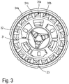
- Figure 4 shows a second embodiment of a cutting unit according to the invention, comprising an external cutting member 20 formed as a cap with an inner cylindrical wall 23. forming the outer limiting wall of the air flow path through the annular gap.
- a carrier 30 is pivoted for a rotational movement about an axis of rotation 5a.
- the carrier is driven by a drive unit (not shown) and transfers the driving force onto a plurality of cutting elements 33a.
- the cutting elements 33a are positioned adjacent to hair entry openings 21a in a circular shaving track around axis of rotation 5a and formed by the external cutting member 20.
- the internal cutting member comprises an inner race 31 and an outer carrier ring 32 connected to and formed integrally with said inner race 31 by a plurality of spokes 36.
- a plurality of fan blades 34a extend from said outer carrier ring 32 forming a fan structure.
- the annular gap is delimited by a wear rim 26 extending circumferentially along the whole inner periphery of the inner cylindrical wall 23.
- the inner circumferential edge of the wear rim 26 forms the external limiting wall of the annular gap in the region of the fan structure.
- the width of the annular gap in this region is shown by double arrowed line 25.
- the width of the annular gap is almost identical to the radial length of the fan blade 3a thus effecting an efficient airflow through the annular gap produced by the fan structure.
- the wear rim may have a radial extension such that it is in contact with the fan blades 34a.
- a single unit or device may fulfill the functions of several items recited in the claims.
- the mere fact that certain measures are recited in mutually different dependent claims does not indicate that a combination of these measures cannot be used to advantage.
- the invention relates to a cutting unit for a shaving apparatus, comprising an external cutting member having a plurality of hair entry openings which define a shaving track, an internal cutting member which is adapted to be rotatable relative to the external cutting member about an axis of rotation, said internal cutting member comprising a carrier adapted to be rotatable about said axis of rotation and a plurality of cutting elements affixed to said carrier, wherein a fan structure is adapted to effect a flow of air from said cutting elements of said internal cutting member through an annular gap positioned, relative to the axis of rotation, radially outward of said carrier between the carrier and the external cutting member, wherein said fan structure is positioned at least partially in said annular gap.
Landscapes
- Life Sciences & Earth Sciences (AREA)
- Forests & Forestry (AREA)
- Engineering & Computer Science (AREA)
- Mechanical Engineering (AREA)
- Dry Shavers And Clippers (AREA)
Priority Applications (1)
| Application Number | Priority Date | Filing Date | Title |
|---|---|---|---|
| EP18204360.4A EP3647002A1 (de) | 2018-11-05 | 2018-11-05 | Schneideeinheit für ein rasiervorrichtung mit einer haarfördernden lüfterstruktur |
Applications Claiming Priority (1)
| Application Number | Priority Date | Filing Date | Title |
|---|---|---|---|
| EP18204360.4A EP3647002A1 (de) | 2018-11-05 | 2018-11-05 | Schneideeinheit für ein rasiervorrichtung mit einer haarfördernden lüfterstruktur |
Publications (1)
| Publication Number | Publication Date |
|---|---|
| EP3647002A1 true EP3647002A1 (de) | 2020-05-06 |
Family
ID=64172377
Family Applications (1)
| Application Number | Title | Priority Date | Filing Date |
|---|---|---|---|
| EP18204360.4A Withdrawn EP3647002A1 (de) | 2018-11-05 | 2018-11-05 | Schneideeinheit für ein rasiervorrichtung mit einer haarfördernden lüfterstruktur |
Country Status (1)
| Country | Link |
|---|---|
| EP (1) | EP3647002A1 (de) |
Citations (8)
| Publication number | Priority date | Publication date | Assignee | Title |
|---|---|---|---|---|
| FR1103679A (fr) * | 1954-07-05 | 1955-11-04 | Rasoir électrique | |
| US2824367A (en) * | 1955-06-22 | 1958-02-25 | Arthur C Mcwilliams | Dry shaver having combination suction and adjustable cutting means |
| US3828430A (en) | 1971-08-19 | 1974-08-13 | Matsushita Electric Works Ltd | Electric dry shaver with cut hair disposal means |
| JPH0197493A (ja) | 1987-10-09 | 1989-04-14 | Junichi Watanabe | 髭剃機 |
| EP0606000A1 (de) * | 1993-01-08 | 1994-07-13 | Izumi Products Company | Trockenrasierapparat |
| DE4326552A1 (de) * | 1993-08-07 | 1995-02-09 | Steffens Heintz Verena | Elektrischer Rasierapparat mit Haarstaubabsaugung |
| WO2000058060A1 (en) * | 1999-03-28 | 2000-10-05 | Barish Benjamin J | Electrical hair remover device and method |
| WO2016184693A1 (en) * | 2015-05-21 | 2016-11-24 | Koninklijke Philips N.V. | Improved cutting unit and shaving head of a shaving device |
-
2018
- 2018-11-05 EP EP18204360.4A patent/EP3647002A1/de not_active Withdrawn
Patent Citations (8)
| Publication number | Priority date | Publication date | Assignee | Title |
|---|---|---|---|---|
| FR1103679A (fr) * | 1954-07-05 | 1955-11-04 | Rasoir électrique | |
| US2824367A (en) * | 1955-06-22 | 1958-02-25 | Arthur C Mcwilliams | Dry shaver having combination suction and adjustable cutting means |
| US3828430A (en) | 1971-08-19 | 1974-08-13 | Matsushita Electric Works Ltd | Electric dry shaver with cut hair disposal means |
| JPH0197493A (ja) | 1987-10-09 | 1989-04-14 | Junichi Watanabe | 髭剃機 |
| EP0606000A1 (de) * | 1993-01-08 | 1994-07-13 | Izumi Products Company | Trockenrasierapparat |
| DE4326552A1 (de) * | 1993-08-07 | 1995-02-09 | Steffens Heintz Verena | Elektrischer Rasierapparat mit Haarstaubabsaugung |
| WO2000058060A1 (en) * | 1999-03-28 | 2000-10-05 | Barish Benjamin J | Electrical hair remover device and method |
| WO2016184693A1 (en) * | 2015-05-21 | 2016-11-24 | Koninklijke Philips N.V. | Improved cutting unit and shaving head of a shaving device |
Similar Documents
| Publication | Publication Date | Title |
|---|---|---|
| EP2463067B1 (de) | Elektrischer Rotationsrasierapparat | |
| US9021777B2 (en) | Cutter guard for a lawn mower | |
| EP2298511B1 (de) | Nasenhaar-Schneidegerät | |
| US10906195B2 (en) | Beard trimmer | |
| US10213930B2 (en) | Beard trimmer | |
| EP2213427B1 (de) | Klingeneinheit für elektrischen Rasierapparat | |
| EP3300856B1 (de) | Bartschneider | |
| JPH114980A (ja) | 電気かみそり | |
| CA1227023A (en) | Hair cutting apparatus | |
| JP4334025B2 (ja) | ひげ剃り器 | |
| JPH0120909B2 (de) | ||
| EP3647002A1 (de) | Schneideeinheit für ein rasiervorrichtung mit einer haarfördernden lüfterstruktur | |
| US20190357435A1 (en) | Hand-Held Horizontal Rotary Trimmer with Vented Baffle | |
| JPH03236887A (ja) | ヘアカッター | |
| US5909928A (en) | Electrical hair remover device and method | |
| EP4274714B1 (de) | Abdichtung einer öffnung, durch die sich eine antriebswelle in eine rasiereinheit für einen rotierenden elektrischen rasierapparat erstreckt | |
| US7065878B2 (en) | Rotary type electric shaver | |
| US2912753A (en) | Air-operated razor | |
| KR20040013331A (ko) | 수동회전식 코털면도기 와 고정날 및 그 제품 | |
| US6941662B2 (en) | Shaving head assembly for a lint shaver | |
| JPS5839182Y2 (ja) | 回転式電気かみそり | |
| JPS6028381Y2 (ja) | 電気かみそり | |
| JPH0740323Y2 (ja) | 電動鼻毛切り具 | |
| JPH0317832Y2 (de) | ||
| JPS5852674B2 (ja) | 回転式電気かみそり |
Legal Events
| Date | Code | Title | Description |
|---|---|---|---|
| PUAI | Public reference made under article 153(3) epc to a published international application that has entered the european phase |
Free format text: ORIGINAL CODE: 0009012 |
|
| STAA | Information on the status of an ep patent application or granted ep patent |
Free format text: STATUS: THE APPLICATION HAS BEEN PUBLISHED |
|
| AK | Designated contracting states |
Kind code of ref document: A1 Designated state(s): AL AT BE BG CH CY CZ DE DK EE ES FI FR GB GR HR HU IE IS IT LI LT LU LV MC MK MT NL NO PL PT RO RS SE SI SK SM TR |
|
| AX | Request for extension of the european patent |
Extension state: BA ME |
|
| STAA | Information on the status of an ep patent application or granted ep patent |
Free format text: STATUS: THE APPLICATION IS DEEMED TO BE WITHDRAWN |
|
| 18D | Application deemed to be withdrawn |
Effective date: 20201107 |