EP3645907B1 - Plate for a drum brake of a motor vehicle, associated drum brake and associated assembly method - Google Patents
Plate for a drum brake of a motor vehicle, associated drum brake and associated assembly method Download PDFInfo
- Publication number
- EP3645907B1 EP3645907B1 EP18749434.9A EP18749434A EP3645907B1 EP 3645907 B1 EP3645907 B1 EP 3645907B1 EP 18749434 A EP18749434 A EP 18749434A EP 3645907 B1 EP3645907 B1 EP 3645907B1
- Authority
- EP
- European Patent Office
- Prior art keywords
- bearing portion
- wheel cylinder
- drum brake
- backing plate
- orifice
- Prior art date
- Legal status (The legal status is an assumption and is not a legal conclusion. Google has not performed a legal analysis and makes no representation as to the accuracy of the status listed.)
- Active
Links
- 238000000034 method Methods 0.000 title claims description 8
- 239000011347 resin Substances 0.000 claims description 11
- 229920005989 resin Polymers 0.000 claims description 11
- 238000012795 verification Methods 0.000 claims description 7
- 241001417494 Sciaenidae Species 0.000 description 9
- 238000004519 manufacturing process Methods 0.000 description 3
- 230000004048 modification Effects 0.000 description 3
- 238000012986 modification Methods 0.000 description 3
- 239000011324 bead Substances 0.000 description 2
- 230000008878 coupling Effects 0.000 description 2
- 238000010168 coupling process Methods 0.000 description 2
- 238000005859 coupling reaction Methods 0.000 description 2
- 238000007789 sealing Methods 0.000 description 2
- 230000008901 benefit Effects 0.000 description 1
- 230000000694 effects Effects 0.000 description 1
- 239000007788 liquid Substances 0.000 description 1
- 229910021645 metal ion Inorganic materials 0.000 description 1
- 239000007769 metal material Substances 0.000 description 1
- 230000008569 process Effects 0.000 description 1
- 230000009467 reduction Effects 0.000 description 1
- 238000006467 substitution reaction Methods 0.000 description 1
Images


Classifications
-
- F—MECHANICAL ENGINEERING; LIGHTING; HEATING; WEAPONS; BLASTING
- F16—ENGINEERING ELEMENTS AND UNITS; GENERAL MEASURES FOR PRODUCING AND MAINTAINING EFFECTIVE FUNCTIONING OF MACHINES OR INSTALLATIONS; THERMAL INSULATION IN GENERAL
- F16D—COUPLINGS FOR TRANSMITTING ROTATION; CLUTCHES; BRAKES
- F16D51/00—Brakes with outwardly-movable braking members co-operating with the inner surface of a drum or the like
- F16D51/16—Brakes with outwardly-movable braking members co-operating with the inner surface of a drum or the like shaped as brake-shoes pivoted on a fixed or nearly-fixed axis
- F16D51/18—Brakes with outwardly-movable braking members co-operating with the inner surface of a drum or the like shaped as brake-shoes pivoted on a fixed or nearly-fixed axis with two brake-shoes
- F16D51/20—Brakes with outwardly-movable braking members co-operating with the inner surface of a drum or the like shaped as brake-shoes pivoted on a fixed or nearly-fixed axis with two brake-shoes extending in opposite directions from their pivots
- F16D51/24—Brakes with outwardly-movable braking members co-operating with the inner surface of a drum or the like shaped as brake-shoes pivoted on a fixed or nearly-fixed axis with two brake-shoes extending in opposite directions from their pivots fluid actuated
-
- F—MECHANICAL ENGINEERING; LIGHTING; HEATING; WEAPONS; BLASTING
- F16—ENGINEERING ELEMENTS AND UNITS; GENERAL MEASURES FOR PRODUCING AND MAINTAINING EFFECTIVE FUNCTIONING OF MACHINES OR INSTALLATIONS; THERMAL INSULATION IN GENERAL
- F16D—COUPLINGS FOR TRANSMITTING ROTATION; CLUTCHES; BRAKES
- F16D65/00—Parts or details
- F16D65/0006—Noise or vibration control
Definitions
- the present invention relates to the field of drum brakes for motor vehicles, more particularly the plates of such drum brakes.
- drum brakes are known, they generally comprise a plate supporting two segments each provided with a brake lining and a wheel cylinder allowing the actuation of these segments.
- the drum brakes of the prior art however have the drawback of being noisy.
- the wheel cylinder is, in a known manner, fixed to the plate by means of one or more fixing screws.
- the vibrations generated are transmitted from the wheel cylinder to the rear axle via the plate.
- the critical frequency associated with this noise is of the order of 1.1 kilohertz.
- the document FR1149905 A3 shows a plate for a drum brake according to the preamble of claim 1.
- the object of the present invention is to propose a quieter solution, easier to manufacture and to assemble, making it possible to overcome at least the main limitations of the state of the art indicated above.
- the invention also relates to a motor vehicle drum brake comprising the plate as described above.
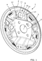
- the plate 1 is characterized in that the receiving zone 9 forms a protruding part in relief with respect to the central base 5, the protruding part in relief comprising a side wall 13 surmounted by the bearing part. 10 and in that the bearing part 10 has a convex shape ( figures 1 , 2 , 3B , 4 , 5 and 7 ).
- this convex shape of the support part 10 makes it possible, when the wheel cylinder 8 is mounted on the plate 1, to minimize the vibratory coupling between the wheel cylinder 8 and the support part 10 of the brake plate 1. , compared to a support portion 10 of planar shape, which is known from the prior art.
- the wheel cylinder 8 when the wheel cylinder 8 is mounted on the plate 1, the wheel cylinder 8 is at least partly in contact with the bearing part 10 of the receiving zone 9 and this contact is minimized, compared to a support portion 10 of planar shape, as is the case in the prior art ( figure 6B ).
- the vibrations during hydraulic braking of the wheel cylinder 8, which are transmitted to the brake plate 1 and then to the rear axle of the vehicle are reduced.
- this configuration simply requires changing the shape of the brake plate 1 at the level of the reception zone 9 without having to add additional elements to the plate 1.
- the invention can therefore easily be integrated into an existing method of manufacturing brake plate 1 without increasing the manufacturing costs thereof.
- this modification in no way degrades either the durability of the plate 1 or the hydraulic function of the plate 1.
- this modification of the shape of the brake plate 1 has very little impact on the assembly process of the brake. drum.
- the bearing part 10 advantageously has a convex shape with a convexity of between 0.2 and 1 millimeter.
- the convex shape is optimal to minimize the coupling between the wheel cylinder 8 and the support part 10.
- the support part 10 of convex shape is advantageously surrounded by a curved edge 14 connecting it to the side wall 13.
- the curved edge 14 advantageously has a radius of curvature of between 2 and 10 millimeters.
- the side wall 13 is advantageously inclined relative to the bearing part 10 by an angle of between 90 ° and 150 °.
- the brake plate 1 as described is advantageously obtained by a method of stamping a metallic material.
- the bearing part 10 is advantageously covered in part or in whole with a resin 15 ( figure 2 ).
- the addition of resin makes it possible to improve the effect of reducing vibrations, but is not necessary. Indeed, the benefit provided by the convex bearing portion 10 may be sufficient.
- the resin 15 is an anaerobic resin forming a one-component liquid sealing gasket and which allows the assembly and sealing of mechanical parts.
- a resin can be polymerized when it is confined and is in the presence of metal ions.
- the resin 15 is preferably the TB 1133EC resin sold by the company THREE BOND®.
- the resin 15 is advantageously applied, for example, in the form of a bead, around the second orifice 11 ( figure 2 ) or on the wheel cylinder 8.
- This bead advantageously has a thickness of between 0.1 and 4 millimeters.
- the plate 1 according to the invention is intended to be mounted fixed relative to the chassis (not shown) of a motor vehicle.
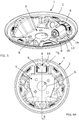
- the invention also relates to a motor vehicle drum brake (not shown) comprising the plate 1 as described above ( figure 7 ).
- a second surface 4 of the plate 1 advantageously supports a hydraulic wheel cylinder 8 at the level of a reception zone 9.
- the reception zone 9 preferably comprises a bearing part 10 at least partly in contact with the wheel cylinder 8. , bearing portion 10 in which is formed a second orifice 11 and a third fixing orifice 12 which is traversed by fixing means and being of convex shape. And the convex-shaped bearing portion 10 and the wheel cylinder 8 may be in contact at a contact interface.
- the support part 10 of convex shape and a surface 18 of the wheel cylinder 8 are facing each other and at a distance to form a space 17 ( figure 6B ).
- the second surface 4 of the plate 1 also supports two segments 7 each comprising a brake lining 19.
- the upper ends 20 of the segments 7 are arranged on either side of the wheel cylinder 8.
- Return means 21, preferably a spring, are fixed between two lower ends 22 of segments 7.
- the drum brake advantageously comprises a drum (not shown) mounted in rotation with respect to the plate 1 and which is suitable and intended to carry a wheel (not shown).
- the invention also relates to a method of assembling a motor vehicle drum brake.
- this verification step makes it possible to check that the contact between the wheel cylinder 8 and the bearing part 10 is indeed minimized.
- the pre-calibrated thickness of the wedge 16 is preferably between 0.1 and 3 millimeters.
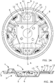
- the wedge 16 advantageously has the shape of a rectangular plate ( figures 5 and 6A )
- the wedge 16 is inserted into the space 17, opposite the fixing means.
Landscapes
- Engineering & Computer Science (AREA)
- General Engineering & Computer Science (AREA)
- Mechanical Engineering (AREA)
- Braking Arrangements (AREA)
Description
La présente invention concerne le domaine des freins à tambour pour véhicule automobile, plus particulièrement les plateaux de tels freins à tambour.The present invention relates to the field of drum brakes for motor vehicles, more particularly the plates of such drum brakes.
De tels freins à tambour sont connus, ils comportent en général un plateau supportant deux segments chacun munis d'une garniture de frein et un cylindre de roue permettant l'actionnement de ces segments.Such drum brakes are known, they generally comprise a plate supporting two segments each provided with a brake lining and a wheel cylinder allowing the actuation of these segments.
En fonctionnement, les freins à tambour de l'art antérieur présentent toutefois l'inconvénient d'être bruyants. En particulier, le cylindre de roue est, de manière connue, fixé au plateau par l'intermédiaire d'une ou de plusieurs vis de fixation. Lors du freinage les vibrations générées sont transmises du cylindre de roue à l'essieu arrière par l'intermédiaire du plateau. Il en résulte la création d'un bruit de crissement qui est amplifié par le plateau. La fréquence critique associée à ce bruit est de l'ordre de 1,1 kilohertz.In operation, the drum brakes of the prior art however have the drawback of being noisy. In particular, the wheel cylinder is, in a known manner, fixed to the plate by means of one or more fixing screws. During braking, the vibrations generated are transmitted from the wheel cylinder to the rear axle via the plate. This results in the creation of a screeching noise which is amplified by the platter. The critical frequency associated with this noise is of the order of 1.1 kilohertz.
Le document
La présente invention a pour but de proposer une solution plus silencieuse, aisée à fabriquer et à assembler, permettant de surmonter au moins les limitations principales de l'état de la technique indiquées ci-dessus.The object of the present invention is to propose a quieter solution, easier to manufacture and to assemble, making it possible to overcome at least the main limitations of the state of the art indicated above.
L'invention concerne un plateau pour frein à tambour de véhicule automobile présentant un bord circulaire et un centre comprenant :
- une première surface apte et destinée à être montée fixe par rapport à un essieu,
- une seconde surface opposée à la première surface,
- la seconde surface comprenant une base centrale sensiblement plane munie d'un premier orifice centré par rapport au centre,
- la seconde surface étant apte et destinée à supporter au moins un segment, et au moins un cylindre de roue hydraulique au niveau d'une zone de réception, la zone de réception comprenant une partie d'appui apte et destinée à être au moins en partie en contact avec le cylindre de roue et dans laquelle est ménagé un deuxième orifice apte et destiné à former un accès au cylindre de roue, au moins un troisième orifice de fixation apte et destiné à être traversé par des moyens de fixation,
- la zone de réception formant une partie en relief saillante par rapport à la base centrale, la partie en relief saillante comprenant une paroi latérale surmontée par la partie d'appui, plateau caractérisé en ce que la partie d'appui présente une forme convexe.
- a first surface suitable and intended to be mounted fixed relative to an axle,
- a second surface opposite the first surface,
- the second surface comprising a substantially planar central base provided with a first orifice centered with respect to the center,
- the second surface being suitable and intended to support at least one segment, and at least one hydraulic wheel cylinder at the level of a reception zone, the reception zone comprising a bearing part suitable and intended to be at least partly in contact with the wheel cylinder and in which is provided a second orifice suitable and intended to form an access to the wheel cylinder, at least one third fixing orifice suitable and intended to be traversed by fixing means,
- the reception area forming a raised part projecting from the central base, the raised part projecting comprising a side wall surmounted by the bearing part, plate characterized in that the bearing part has a convex shape.
L'invention concerne également un frein à tambour de véhicule automobile comprenant le plateau tel que décrit précédemment.The invention also relates to a motor vehicle drum brake comprising the plate as described above.
L'invention concerne également un procédé d'assemblage d'un frein à tambour de véhicule automobile caractérisé en ce qu'il comporte au moins les étapes suivantes :
- a) une étape de montage d'un cylindre de roue sur un plateau tel que décrit précédemment, lors de laquelle un cylindre de roue est monté sur la partie d'appui de forme convexe et est fixé à la partie d'appui par des moyens de fixation au travers du troisième orifice,
- b) une étape de vérification lors de laquelle une cale présentant une épaisseur pré-calibrée est interposée dans un espace entre la partie d'appui et la surface du cylindre de roue situé en regard de la partie d'appui.
- a) a step of mounting a wheel cylinder on a plate as described above, during which a wheel cylinder is mounted on the support part of convex shape and is fixed to the support part by means fixing through the third hole,
- b) a verification step during which a shim having a pre-calibrated thickness is interposed in a space between the bearing part and the surface of the wheel cylinder located opposite the bearing part.
L'invention sera mieux comprise, grâce à la description ci-après, qui se rapporte à un mode de réalisation préféré, donné à titre d'exemple non limitatif, et expliqué avec référence aux dessins schématiques annexés, dans lesquels :
- la
figure 1 est une vue en perspective d'un plateau de frein à tambour selon l'invention, - la
figure 2 est une vue en perspective du plateau de frein à tambour représenté à lafigure 1 avec de la résine, - la
figure 3A est une vue de face du plateau de frein à tambour représenté à lafigure 1 , - la
figure 3B est une vue en coupe selon le plan sécant A-A du plateau de frein à tambour représenté à lafigure 3A , - la
figure 4 est une vue en perspective du plateau de frein à tambour représenté à lafigure 1 ou à lafigure 2 muni d'un cylindre de roue, - la
figure 5 est une vue en perspective du plateau de frein à tambour représenté à lafigure 4 montrant la cale, - la
figure 6A est une vue de face du plateau de frein à tambour représenté à lafigure 5 , - la
figure 6B est une vue en coupe selon le plan sécant B-B du plateau de frein à tambour représenté à lafigure 6A , et - la
figure 7 est une vue en perspective d'un frein à tambour selon l'invention.
- the
figure 1 is a perspective view of a drum brake plate according to the invention, - the
figure 2 is a perspective view of the drum brake plate shown infigure 1 with resin, - the
figure 3A is a front view of the drum brake plate shown infigure 1 , - the
figure 3B is a sectional view along the secant plane AA of the drum brake plate shown infigure 3A , - the
figure 4 is a perspective view of the drum brake plate shown infigure 1 or at thefigure 2 fitted with a wheel cylinder, - the
figure 5 is a perspective view of the drum brake plate shown infigure 4 showing the wedge, - the
figure 6A is a front view of the drum brake plate shown infigure 5 , - the
figure 6B is a sectional view along the secant plane BB of the drum brake plate shown infigure 6A , and - the
figure 7 is a perspective view of a drum brake according to the invention.
Le plateau 1 pour frein à tambour de véhicule automobile présentant un bord circulaire 2 et un centre O comprend :
- une première surface 3 apte et destinée à être montée fixe par rapport à un essieu,
- une
seconde surface 4 opposée à la première surface 3, - la
seconde surface 4 comprenant une base centrale 5 sensiblement plane munie d'unpremier orifice 6 centré par rapport au centre O, - la
seconde surface 4 étant apte et destinée à supporter au moins unsegment 7, et au moins un cylindre deroue 8 hydraulique au niveau d'une zone deréception 9, la zone deréception 9 comprenant une partie d'appui 10 apte et destinée à être au moins en partie en contact avec le cylindre deroue 8 et dans laquelle est ménagé undeuxième orifice 11 apte et destiné à former un accès au cylindre deroue 8, au moins untroisième orifice 12 de fixation apte et destiné à être traversé par des moyens de fixation (non représentés).
- a first surface 3 suitable and intended to be mounted fixed relative to an axle,
- a
second surface 4 opposite to the first surface 3, - the
second surface 4 comprising a substantially planarcentral base 5 provided with afirst orifice 6 centered with respect to the center O, - the
second surface 4 being suitable and intended to support at least onesegment 7, and at least onehydraulic wheel cylinder 8 at the level of areception zone 9, thereception zone 9 comprising abearing part 10 suitable and intended to be at least partially in contact with thewheel cylinder 8 and in which is provided asecond orifice 11 suitable and intended to form an access to thewheel cylinder 8, at least onethird fixing orifice 12 suitable and intended to be traversed by fixing means (not shown).
Conformément à l'invention, le plateau 1 est caractérisé en ce que la zone de réception 9 forme une partie en relief saillante par rapport à la base centrale 5, la partie en relief saillante comprenant une paroi latérale 13 surmontée par la partie d'appui 10 et en ce que la partie d'appui 10 présente une forme convexe (
Avantageusement, cette forme convexe de la partie d'appui 10 permet, lorsque le cylindre de roue 8 est monté sur le plateau 1, de minimiser le couplage vibratoire entre le cylindre de roue 8 et la partie d'appui 10 du plateau 1 de frein, comparativement à une partie d'appui 10 de forme plane, qui est connue de l'art antérieur. Dans cette configuration, lorsque le cylindre de roue 8 est monté sur le plateau 1, le cylindre de roue 8 est au moins en partie en contact avec la partie d'appui 10 de la zone de réception 9 et ce contact est minimisé, comparativement à une partie d'appui 10 de forme plane, comme c'est le cas dans l'art antérieur (
La partie d'appui 10 présente avantageusement une forme convexe de convexité comprise entre 0,2 et 1 millimètre.The bearing
Avantageusement, dans cette plage de valeur de convexité, la forme convexe est optimale pour minimiser le couplage entre le cylindre de roue 8 et la partie d'appui 10.Advantageously, in this range of convexity value, the convex shape is optimal to minimize the coupling between the
La partie d'appui 10 de forme convexe est avantageusement entourée par un bord courbé 14 la reliant à la paroi latérale 13.The
Dans ce cas, le bord courbé 14 présente avantageusement un rayon de courbure compris entre 2 et 10 millimètres. Et la paroi latérale 13 est avantageusement inclinée par rapport à la partie d'appui 10 d'un angle compris entre 90° et 150°.In this case, the
Le plateau 1 de frein tel que décrit est avantageusement obtenu par un procédé d'emboutissage d'un matériau métallique.The
De manière facultative, la partie d'appui 10 est avantageusement recouverte en partie ou en totalité d'une résine 15 (
Avantageusement, l'apport de résine 15 permet d'améliorer l'effet de réduction des vibrations, mais n'est pas nécessaire. En effet, le bénéfice procuré par la partie d'appui 10 convexe peut être suffisant.Advantageously, the addition of resin makes it possible to improve the effect of reducing vibrations, but is not necessary. Indeed, the benefit provided by the
Préférentiellement, la résine 15 est une résine anaérobie formant un joint liquide d'étanchéité mono composant et qui permet l'assemblage et l'étanchéité de pièces mécaniques. Une telle résine 15 peut être polymérisée lorsqu'elle est confinée et est en présence d'ions métalliques.Preferably, the
Par exemple, la résine 15 est préférentiellement la résine TB 1133EC commercialisée par la société THREE BOND®.For example, the
La résine 15 est avantageusement appliquée, par exemple, sous la forme d'un cordon, autour du deuxième orifice 11 (
Le plateau 1 selon l'invention est destinée à être monté fixe par rapport au châssis (non représenté) d'un véhicule automobile.The
L'invention concerne également un frein à tambour de véhicule automobile (non représenté) comprenant le plateau 1 tel que décrit précédemment (
Une seconde surface 4 du plateau 1 supporte avantageusement un cylindre de roue 8 hydraulique au niveau d'une zone de réception 9. La zone de réception 9 comprend préférentiellement une partie d'appui 10 au moins en partie en contact avec le cylindre de roue 8, partie d'appui 10 dans laquelle est ménagé un deuxième orifice 11 et un troisième orifice 12 de fixation qui est traversé par des moyens de fixation et étant de forme convexe. Et la partie d'appui 10 de forme convexe et le cylindre de roue 8 peuvent être en contact au niveau d'une interface de contact.A
En dehors de cette interface de contact, la partie d'appui 10 de forme convexe et une surface 18 du cylindre de roue 8 sont en regard l'un de l'autre et à distance pour former un espace 17 (
La seconde surface 4 du plateau 1 supporte également deux segments 7 comportant chacun une garniture de frein 19.The
Plus particulièrement, les extrémités supérieures 20 des segments 7 sont disposées de part et d'autre du cylindre de roue 8.More particularly, the upper ends 20 of the
Des moyens de rappel 21, préférentiellement un ressort, sont fixés entre deux extrémités inférieures 22 des segments 7.Return means 21, preferably a spring, are fixed between two lower ends 22 of
Le frein à tambour comprend avantageusement un tambour (non représenté) monté en rotation par rapport au plateau 1 et qui est apte et destiné à porter une roue (non représentée).The drum brake advantageously comprises a drum (not shown) mounted in rotation with respect to the
L'invention concerne également un procédé d'assemblage d'un frein à tambour de véhicule automobile.The invention also relates to a method of assembling a motor vehicle drum brake.
Conformément à l'invention, le procédé d'assemblage est caractérisé en ce qu'il comporte au moins les étapes suivantes :
- a) une étape de montage d'un cylindre de roue 8
sur un plateau 1 tel que décrit précédemment, lors de laquelle un cylindre de roue 8 est monté sur le partie d'appui 10 de forme convexe et est fixé à la partie d'appui 10 par des moyens de fixation au travers du troisième orifice 12, - b) une étape de vérification lors de laquelle une
cale 16 présentant une épaisseur pré-calibrée est interposée dans un espace 17 entre la partie d'appui 10 et lasurface 18 du cylindre de roue 8 situé en regard de la partie d'appui 10 (figures 5, 6A et6B ).
- a) a step of mounting a
wheel cylinder 8 on aplate 1 as described above, during which awheel cylinder 8 is mounted on thesupport part 10 of convex shape and is fixed to the part ofsupport 10 by fixing means through thethird orifice 12, - b) a verification step during which a
shim 16 having a pre-calibrated thickness is interposed in aspace 17 between the bearingpart 10 and thesurface 18 of thewheel cylinder 8 located opposite the support part 10 (figures 5, 6A and6B ).
Avantageusement, cet étape de vérification permet de contrôler que le contact entre le cylindre de roue 8 et la partie d'appui 10 est bien minimisé.Advantageously, this verification step makes it possible to check that the contact between the
Préférentiellement, l'épaisseur pré-calibrée de la cale 16 est préférentiellement comprise entre 0.1 et 3 millimètres.Preferably, the pre-calibrated thickness of the
La cale 16 présente avantageusement la forme d'une plaque de forme rectangulaire (
Lors de l'étape de vérification b), la cale 16 est insérée dans l'espace 17, à l'opposé des moyens de fixation.During the verification step b), the
Cette façon de procéder facilite l'étape de vérification.This way of proceeding facilitates the verification step.
Les parties, éléments, composants, pièces et moyens suivants de l'invention sont référencés comme suit sur les dessins annexés :
- 1
- plateau
- 2
- bord circulaire
- 3
- première surface
- 4
- deuxième surface
- 5
- base
- 6
- premier orifice
- 7
- segment
- 8
- cylindre de roue
- 9
- zone de réception
- 10
- partie d'appui
- 11
- deuxième orifice
- 12
- troisième orifice
- 13
- paroi latérale
- 14
- bord courbé
- 15
- résine
- 16
- cale
- 17
- espace
- 18
- surface
- 19
- garniture de frein
- 20
- extrémité supérieure
- 21
- moyens de rappel
- 22
- extrémité inférieure
- 1
- tray
- 2
- circular edge
- 3
- first surface
- 4
- second surface
- 5
- based
- 6
- first hole
- 7
- segment
- 8
- wheel cylinder
- 9
- reception area
- 10
- support part
- 11
- second port
- 12
- third port
- 13
- side wall
- 14
- curved edge
- 15
- resin
- 16
- hold
- 17
- space
- 18
- area
- 19
- brake lining
- 20
- upper end
- 21
- means of recall
- 22
- lower end
Bien entendu, l'invention n'est pas limitée au mode de réalisation décrit et représenté aux dessins annexés. Des modifications restent possibles, notamment du point de vue de la constitution des divers éléments ou par substitution d'équivalents techniques, sans sortir pour autant du domaine de protection de l'invention tel que défini par les revendications.Of course, the invention is not limited to the embodiment described and shown in the accompanying drawings. Modifications remain possible, in particular from the point of view of the constitution of the various elements or by substitution of technical equivalents, without thereby departing from the field of protection of the invention as defined by the claims.
Claims (10)
- Backing plate (1) for a motor vehicle drum brake having a circular edge (2) and a centre O, comprising:a first surface (3) able and intended to be mounted fixed with respect to an axle,a second surface (4) opposite the first surface (3) ,the second surface (4) comprising a substantially planar central base (5) provided with a first orifice (6) centred with respect to the centre O,the second surface (4) being able and intended to support at least one tube (7), and at least one hydraulic wheel cylinder (8) at a receiving region (9), the receiving region (9) comprising a bearing portion (10) able and intended to be at least partly in contact with the wheel cylinder (8) and in which there is formed a second orifice (11) able and intended to form an access to the wheel cylinder (8), and at least one third fastening orifice (12) able and intended to be traversed by fastening means,the receiving region (9) forming a projecting relief portion with respect to the central base (5), the projecting relief portion comprising a lateral wall (13) surmounted by the bearing portion (10), which backing plate is characterized in that the bearing portion (10) has a convex shape.
- Backing plate according to Claim 1, characterized in that the bearing portion (10) has a convex shape with a convexity of between 0.2 and 1 millimetre.
- Backing plate according to either one of Claims 1 and 2, characterized in that the bearing portion (10) of convex shape is surrounded by a curved edge (14) connecting it to the lateral wall (13).
- Backing plate according to Claim 3, characterized in that the curved edge (14) has a radius of curvature of between 2 and 10 millimetres, and in that the lateral wall (13) is inclined with respect to the bearing portion (10) by an angle of between 90° and 150°.
- Backing plate according to any one of Claims 1 to 4, characterized in that the bearing portion (10) is partly or completely covered by a resin (15).
- Motor vehicle drum brake comprising the backing plate (1) according to any one of Claims 1 to 5.
- Drum brake according to Claim 6, characterized in that a second surface (4) of the backing plate (1) supports a hydraulic wheel cylinder (8) at a receiving region (9), the receiving region (9) comprising a bearing portion (10) at least partly in contact with the wheel cylinder (8), in which bearing portion (10) there is formed a second orifice (11) and a third fastening orifice (12) which is traversed by fastening means and being of convex shape, and in that the bearing portion (10) of convex shape and the wheel cylinder (8) are in contact and form a contact interface.
- Drum brake according to Claim 7, characterized in that, outside this contact interface, the bearing portion (10) of convex shape and a surface (18) of the wheel cylinder (8) face one another and are at a distance to form a space (17).
- Method for assembling a motor vehicle drum brake, characterized in that it comprises at least the following steps:a) a step of mounting a wheel cylinder (8) on a backing plate (1) according to any one of Claims 1 to 5, during which a wheel cylinder (8) is mounted on the bearing portion (10) of convex shape and is fixed to the bearing portion (10) by fastening means through the third orifice (12),b) a verification step during which a shim (16) having a precalibrated thickness is interposed in a space (17) between the bearing portion (10) and the surface (18) of the wheel cylinder (8) situated facing the bearing portion (10).
- Assembly method according to Claim 9, characterized in that, during the verification step b), the shim (16) is inserted into the space (17) away from the fastening means.
Applications Claiming Priority (2)
| Application Number | Priority Date | Filing Date | Title |
|---|---|---|---|
| FR1756024A FR3068418B1 (en) | 2017-06-29 | 2017-06-29 | MOTOR VEHICLE DRUM BRAKE PLATE, ASSOCIATED DRUM BRAKE AND ASSOCIATED ASSEMBLY METHOD |
| PCT/FR2018/051413 WO2019002715A1 (en) | 2017-06-29 | 2018-06-14 | Plate for a drum brake of a motor vehicle, associated drum brake and associated assembly method |
Publications (2)
| Publication Number | Publication Date |
|---|---|
| EP3645907A1 EP3645907A1 (en) | 2020-05-06 |
| EP3645907B1 true EP3645907B1 (en) | 2021-05-05 |
Family
ID=60020021
Family Applications (1)
| Application Number | Title | Priority Date | Filing Date |
|---|---|---|---|
| EP18749434.9A Active EP3645907B1 (en) | 2017-06-29 | 2018-06-14 | Plate for a drum brake of a motor vehicle, associated drum brake and associated assembly method |
Country Status (4)
| Country | Link |
|---|---|
| EP (1) | EP3645907B1 (en) |
| ES (1) | ES2882215T3 (en) |
| FR (1) | FR3068418B1 (en) |
| WO (1) | WO2019002715A1 (en) |
Family Cites Families (2)
| Publication number | Priority date | Publication date | Assignee | Title |
|---|---|---|---|---|
| FR1149905A (en) * | 1956-04-16 | 1958-01-03 | New brake control device | |
| US3200908A (en) * | 1963-06-05 | 1965-08-17 | Bendix Corp | Fluid motor, backing plate connection |
-
2017
- 2017-06-29 FR FR1756024A patent/FR3068418B1/en not_active Expired - Fee Related
-
2018
- 2018-06-14 EP EP18749434.9A patent/EP3645907B1/en active Active
- 2018-06-14 ES ES18749434T patent/ES2882215T3/en active Active
- 2018-06-14 WO PCT/FR2018/051413 patent/WO2019002715A1/en unknown
Also Published As
| Publication number | Publication date |
|---|---|
| EP3645907A1 (en) | 2020-05-06 |
| FR3068418A1 (en) | 2019-01-04 |
| FR3068418B1 (en) | 2019-08-02 |
| WO2019002715A1 (en) | 2019-01-03 |
| ES2882215T3 (en) | 2021-12-01 |
Similar Documents
| Publication | Publication Date | Title |
|---|---|---|
| EP1591686B1 (en) | Mounting system for disc brake pads and disc brake using such a system. | |
| EP2072850B1 (en) | System for installing a disc brake shoe | |
| EP0203841B1 (en) | Disc brake spring | |
| FR2801545A1 (en) | VEHICLE SEAT BACKREST STRUCTURE | |
| FR2880607A1 (en) | Adjustable steering column locking device for motor vehicle, has flange forming cam follower and comprising oblong hole with profile complementary to that of projections of movable cam of locking unit | |
| EP0080949A1 (en) | Disk brake, and brake shoe for such a brake | |
| EP0536008B1 (en) | Brake lining provided with a wear indicator device and disc brake equipped with such an element | |
| EP3645907B1 (en) | Plate for a drum brake of a motor vehicle, associated drum brake and associated assembly method | |
| EP2114723B1 (en) | Arrangement for attaching the seat of an automobile | |
| EP0694134B1 (en) | Friction element assembly fitted with a spring for disk brakes | |
| FR2936999A1 (en) | Right front wing's rear edge fixing bracket for front pillar of motor vehicle, has zone constituted of parallel flanges, wall and wall part to limit movement of wing of vehicle during low speed frontal impact i.e. reparability impact | |
| FR2861647A1 (en) | FLEXIBLE AXLE HAVING TRANSVERSE STIFFNESS INCREASED BY AT LEAST ONE SPRING CUTTING PART, SPRING CUP AND CORRESPONDING VEHICLE | |
| FR2925634A1 (en) | Brake friction pad mounting device for vehicle, has sliding plate with end opposite to another end of plate exerting pressure force on lateral side of housing when mounting device is mounted on yoke joint | |
| EP2643169B1 (en) | Vehicle ground-contacting element forming a hollow body and method for manufacturing such a ground-contacting element | |
| FR2729197A1 (en) | BRAKE LINING, IN PARTICULAR FOR RAILWAY VEHICLE | |
| EP1657465B1 (en) | Decoupling element to be interposed between a piston and a friction element of a disc brake | |
| FR2890422A1 (en) | COMPOSITE ASSEMBLY ASSEMBLY, PREFERABLY SEALING RING, AND METHOD FOR PRODUCING THE SAME | |
| FR2518933A1 (en) | Double wheel for road vehicle - has disc with thrust face to engage brake drum and retaining studs | |
| WO2023031539A1 (en) | Covering element for a floating-caliper disc brake, which is fixed to a carrier of the brake | |
| WO2019020898A1 (en) | Wheel for mouting a tyre-type device for a vehicle | |
| EP1468894B1 (en) | Steering assembly with increased natural vibration frequency and corresponding vehicle | |
| FR3024190A1 (en) | BRAKE SKATE EQUIPPED WITH AN ANTI-NOISE DEVICE | |
| FR3137339A1 (en) | Body stiffening device around a rear shock absorber. | |
| FR3115339A1 (en) | BRAKING DEVICE COMPRISING A STAMPED METAL BOWL AND VEHICLE COMPRISING SUCH A BRAKING DEVICE | |
| FR3095780A1 (en) | Rear axle comprising a reinforcing member mounted between a longitudinal arm, a transverse cross member and a stabilizing bar |
Legal Events
| Date | Code | Title | Description |
|---|---|---|---|
| STAA | Information on the status of an ep patent application or granted ep patent |
Free format text: STATUS: UNKNOWN |
|
| STAA | Information on the status of an ep patent application or granted ep patent |
Free format text: STATUS: THE INTERNATIONAL PUBLICATION HAS BEEN MADE |
|
| PUAI | Public reference made under article 153(3) epc to a published international application that has entered the european phase |
Free format text: ORIGINAL CODE: 0009012 |
|
| STAA | Information on the status of an ep patent application or granted ep patent |
Free format text: STATUS: REQUEST FOR EXAMINATION WAS MADE |
|
| 17P | Request for examination filed |
Effective date: 20200108 |
|
| AK | Designated contracting states |
Kind code of ref document: A1 Designated state(s): AL AT BE BG CH CY CZ DE DK EE ES FI FR GB GR HR HU IE IS IT LI LT LU LV MC MK MT NL NO PL PT RO RS SE SI SK SM TR |
|
| AX | Request for extension of the european patent |
Extension state: BA ME |
|
| DAV | Request for validation of the european patent (deleted) | ||
| DAX | Request for extension of the european patent (deleted) | ||
| GRAP | Despatch of communication of intention to grant a patent |
Free format text: ORIGINAL CODE: EPIDOSNIGR1 |
|
| STAA | Information on the status of an ep patent application or granted ep patent |
Free format text: STATUS: GRANT OF PATENT IS INTENDED |
|
| INTG | Intention to grant announced |
Effective date: 20201223 |
|
| GRAS | Grant fee paid |
Free format text: ORIGINAL CODE: EPIDOSNIGR3 |
|
| GRAA | (expected) grant |
Free format text: ORIGINAL CODE: 0009210 |
|
| STAA | Information on the status of an ep patent application or granted ep patent |
Free format text: STATUS: THE PATENT HAS BEEN GRANTED |
|
| AK | Designated contracting states |
Kind code of ref document: B1 Designated state(s): AL AT BE BG CH CY CZ DE DK EE ES FI FR GB GR HR HU IE IS IT LI LT LU LV MC MK MT NL NO PL PT RO RS SE SI SK SM TR |
|
| REG | Reference to a national code |
Ref country code: GB Ref legal event code: FG4D Free format text: NOT ENGLISH |
|
| REG | Reference to a national code |
Ref country code: CH Ref legal event code: EP |
|
| REG | Reference to a national code |
Ref country code: AT Ref legal event code: REF Ref document number: 1390183 Country of ref document: AT Kind code of ref document: T Effective date: 20210515 |
|
| REG | Reference to a national code |
Ref country code: IE Ref legal event code: FG4D Free format text: LANGUAGE OF EP DOCUMENT: FRENCH |
|
| REG | Reference to a national code |
Ref country code: DE Ref legal event code: R096 Ref document number: 602018016788 Country of ref document: DE |
|
| REG | Reference to a national code |
Ref country code: RO Ref legal event code: EPE |
|
| REG | Reference to a national code |
Ref country code: LT Ref legal event code: MG9D |
|
| REG | Reference to a national code |
Ref country code: AT Ref legal event code: MK05 Ref document number: 1390183 Country of ref document: AT Kind code of ref document: T Effective date: 20210505 |
|
| PG25 | Lapsed in a contracting state [announced via postgrant information from national office to epo] |
Ref country code: AT Free format text: LAPSE BECAUSE OF FAILURE TO SUBMIT A TRANSLATION OF THE DESCRIPTION OR TO PAY THE FEE WITHIN THE PRESCRIBED TIME-LIMIT Effective date: 20210505 Ref country code: BG Free format text: LAPSE BECAUSE OF FAILURE TO SUBMIT A TRANSLATION OF THE DESCRIPTION OR TO PAY THE FEE WITHIN THE PRESCRIBED TIME-LIMIT Effective date: 20210805 Ref country code: LT Free format text: LAPSE BECAUSE OF FAILURE TO SUBMIT A TRANSLATION OF THE DESCRIPTION OR TO PAY THE FEE WITHIN THE PRESCRIBED TIME-LIMIT Effective date: 20210505 Ref country code: HR Free format text: LAPSE BECAUSE OF FAILURE TO SUBMIT A TRANSLATION OF THE DESCRIPTION OR TO PAY THE FEE WITHIN THE PRESCRIBED TIME-LIMIT Effective date: 20210505 Ref country code: FI Free format text: LAPSE BECAUSE OF FAILURE TO SUBMIT A TRANSLATION OF THE DESCRIPTION OR TO PAY THE FEE WITHIN THE PRESCRIBED TIME-LIMIT Effective date: 20210505 |
|
| PG25 | Lapsed in a contracting state [announced via postgrant information from national office to epo] |
Ref country code: IS Free format text: LAPSE BECAUSE OF FAILURE TO SUBMIT A TRANSLATION OF THE DESCRIPTION OR TO PAY THE FEE WITHIN THE PRESCRIBED TIME-LIMIT Effective date: 20210905 Ref country code: GR Free format text: LAPSE BECAUSE OF FAILURE TO SUBMIT A TRANSLATION OF THE DESCRIPTION OR TO PAY THE FEE WITHIN THE PRESCRIBED TIME-LIMIT Effective date: 20210806 Ref country code: LV Free format text: LAPSE BECAUSE OF FAILURE TO SUBMIT A TRANSLATION OF THE DESCRIPTION OR TO PAY THE FEE WITHIN THE PRESCRIBED TIME-LIMIT Effective date: 20210505 Ref country code: PL Free format text: LAPSE BECAUSE OF FAILURE TO SUBMIT A TRANSLATION OF THE DESCRIPTION OR TO PAY THE FEE WITHIN THE PRESCRIBED TIME-LIMIT Effective date: 20210505 Ref country code: NO Free format text: LAPSE BECAUSE OF FAILURE TO SUBMIT A TRANSLATION OF THE DESCRIPTION OR TO PAY THE FEE WITHIN THE PRESCRIBED TIME-LIMIT Effective date: 20210805 Ref country code: PT Free format text: LAPSE BECAUSE OF FAILURE TO SUBMIT A TRANSLATION OF THE DESCRIPTION OR TO PAY THE FEE WITHIN THE PRESCRIBED TIME-LIMIT Effective date: 20210906 Ref country code: SE Free format text: LAPSE BECAUSE OF FAILURE TO SUBMIT A TRANSLATION OF THE DESCRIPTION OR TO PAY THE FEE WITHIN THE PRESCRIBED TIME-LIMIT Effective date: 20210505 Ref country code: RS Free format text: LAPSE BECAUSE OF FAILURE TO SUBMIT A TRANSLATION OF THE DESCRIPTION OR TO PAY THE FEE WITHIN THE PRESCRIBED TIME-LIMIT Effective date: 20210505 |
|
| REG | Reference to a national code |
Ref country code: ES Ref legal event code: FG2A Ref document number: 2882215 Country of ref document: ES Kind code of ref document: T3 Effective date: 20211201 |
|
| REG | Reference to a national code |
Ref country code: NL Ref legal event code: MP Effective date: 20210505 |
|
| PG25 | Lapsed in a contracting state [announced via postgrant information from national office to epo] |
Ref country code: NL Free format text: LAPSE BECAUSE OF FAILURE TO SUBMIT A TRANSLATION OF THE DESCRIPTION OR TO PAY THE FEE WITHIN THE PRESCRIBED TIME-LIMIT Effective date: 20210505 |
|
| PG25 | Lapsed in a contracting state [announced via postgrant information from national office to epo] |
Ref country code: CZ Free format text: LAPSE BECAUSE OF FAILURE TO SUBMIT A TRANSLATION OF THE DESCRIPTION OR TO PAY THE FEE WITHIN THE PRESCRIBED TIME-LIMIT Effective date: 20210505 Ref country code: DK Free format text: LAPSE BECAUSE OF FAILURE TO SUBMIT A TRANSLATION OF THE DESCRIPTION OR TO PAY THE FEE WITHIN THE PRESCRIBED TIME-LIMIT Effective date: 20210505 Ref country code: SM Free format text: LAPSE BECAUSE OF FAILURE TO SUBMIT A TRANSLATION OF THE DESCRIPTION OR TO PAY THE FEE WITHIN THE PRESCRIBED TIME-LIMIT Effective date: 20210505 Ref country code: SK Free format text: LAPSE BECAUSE OF FAILURE TO SUBMIT A TRANSLATION OF THE DESCRIPTION OR TO PAY THE FEE WITHIN THE PRESCRIBED TIME-LIMIT Effective date: 20210505 Ref country code: EE Free format text: LAPSE BECAUSE OF FAILURE TO SUBMIT A TRANSLATION OF THE DESCRIPTION OR TO PAY THE FEE WITHIN THE PRESCRIBED TIME-LIMIT Effective date: 20210505 |
|
| REG | Reference to a national code |
Ref country code: CH Ref legal event code: PL |
|
| REG | Reference to a national code |
Ref country code: DE Ref legal event code: R097 Ref document number: 602018016788 Country of ref document: DE |
|
| REG | Reference to a national code |
Ref country code: BE Ref legal event code: MM Effective date: 20210630 |
|
| PLBE | No opposition filed within time limit |
Free format text: ORIGINAL CODE: 0009261 |
|
| STAA | Information on the status of an ep patent application or granted ep patent |
Free format text: STATUS: NO OPPOSITION FILED WITHIN TIME LIMIT |
|
| PG25 | Lapsed in a contracting state [announced via postgrant information from national office to epo] |
Ref country code: MC Free format text: LAPSE BECAUSE OF FAILURE TO SUBMIT A TRANSLATION OF THE DESCRIPTION OR TO PAY THE FEE WITHIN THE PRESCRIBED TIME-LIMIT Effective date: 20210505 Ref country code: LU Free format text: LAPSE BECAUSE OF NON-PAYMENT OF DUE FEES Effective date: 20210614 |
|
| 26N | No opposition filed |
Effective date: 20220208 |
|
| PG25 | Lapsed in a contracting state [announced via postgrant information from national office to epo] |
Ref country code: LI Free format text: LAPSE BECAUSE OF NON-PAYMENT OF DUE FEES Effective date: 20210630 Ref country code: IE Free format text: LAPSE BECAUSE OF NON-PAYMENT OF DUE FEES Effective date: 20210614 Ref country code: CH Free format text: LAPSE BECAUSE OF NON-PAYMENT OF DUE FEES Effective date: 20210630 |
|
| PG25 | Lapsed in a contracting state [announced via postgrant information from national office to epo] |
Ref country code: IS Free format text: LAPSE BECAUSE OF FAILURE TO SUBMIT A TRANSLATION OF THE DESCRIPTION OR TO PAY THE FEE WITHIN THE PRESCRIBED TIME-LIMIT Effective date: 20210905 Ref country code: AL Free format text: LAPSE BECAUSE OF FAILURE TO SUBMIT A TRANSLATION OF THE DESCRIPTION OR TO PAY THE FEE WITHIN THE PRESCRIBED TIME-LIMIT Effective date: 20210505 |
|
| PG25 | Lapsed in a contracting state [announced via postgrant information from national office to epo] |
Ref country code: BE Free format text: LAPSE BECAUSE OF NON-PAYMENT OF DUE FEES Effective date: 20210630 |
|
| GBPC | Gb: european patent ceased through non-payment of renewal fee |
Effective date: 20220614 |
|
| PG25 | Lapsed in a contracting state [announced via postgrant information from national office to epo] |
Ref country code: GB Free format text: LAPSE BECAUSE OF NON-PAYMENT OF DUE FEES Effective date: 20220614 |
|
| PG25 | Lapsed in a contracting state [announced via postgrant information from national office to epo] |
Ref country code: CY Free format text: LAPSE BECAUSE OF FAILURE TO SUBMIT A TRANSLATION OF THE DESCRIPTION OR TO PAY THE FEE WITHIN THE PRESCRIBED TIME-LIMIT Effective date: 20210505 |
|
| PG25 | Lapsed in a contracting state [announced via postgrant information from national office to epo] |
Ref country code: HU Free format text: LAPSE BECAUSE OF FAILURE TO SUBMIT A TRANSLATION OF THE DESCRIPTION OR TO PAY THE FEE WITHIN THE PRESCRIBED TIME-LIMIT; INVALID AB INITIO Effective date: 20180614 |
|
| PGFP | Annual fee paid to national office [announced via postgrant information from national office to epo] |
Ref country code: ES Payment date: 20230703 Year of fee payment: 6 |
|
| PG25 | Lapsed in a contracting state [announced via postgrant information from national office to epo] |
Ref country code: MK Free format text: LAPSE BECAUSE OF FAILURE TO SUBMIT A TRANSLATION OF THE DESCRIPTION OR TO PAY THE FEE WITHIN THE PRESCRIBED TIME-LIMIT Effective date: 20210505 |
|
| PG25 | Lapsed in a contracting state [announced via postgrant information from national office to epo] |
Ref country code: TR Free format text: LAPSE BECAUSE OF FAILURE TO SUBMIT A TRANSLATION OF THE DESCRIPTION OR TO PAY THE FEE WITHIN THE PRESCRIBED TIME-LIMIT Effective date: 20210505 |
|
| PGFP | Annual fee paid to national office [announced via postgrant information from national office to epo] |
Ref country code: DE Payment date: 20240521 Year of fee payment: 7 |
|
| PGFP | Annual fee paid to national office [announced via postgrant information from national office to epo] |
Ref country code: RO Payment date: 20240612 Year of fee payment: 7 Ref country code: IT Payment date: 20240522 Year of fee payment: 7 Ref country code: FR Payment date: 20240522 Year of fee payment: 7 |