EP3645313B1 - Fahrzeugreifen - Google Patents
Fahrzeugreifen Download PDFInfo
- Publication number
- EP3645313B1 EP3645313B1 EP18825292.8A EP18825292A EP3645313B1 EP 3645313 B1 EP3645313 B1 EP 3645313B1 EP 18825292 A EP18825292 A EP 18825292A EP 3645313 B1 EP3645313 B1 EP 3645313B1
- Authority
- EP
- European Patent Office
- Prior art keywords
- tire
- tread
- road
- zone
- radially outer
- Prior art date
- Legal status (The legal status is an assumption and is not a legal conclusion. Google has not performed a legal analysis and makes no representation as to the accuracy of the status listed.)
- Active
Links
Images


Classifications
-
- B—PERFORMING OPERATIONS; TRANSPORTING
- B60—VEHICLES IN GENERAL
- B60C—VEHICLE TYRES; TYRE INFLATION; TYRE CHANGING; CONNECTING VALVES TO INFLATABLE ELASTIC BODIES IN GENERAL; DEVICES OR ARRANGEMENTS RELATED TO TYRES
- B60C11/00—Tyre tread bands; Tread patterns; Anti-skid inserts
- B60C11/0083—Tyre tread bands; Tread patterns; Anti-skid inserts characterised by the curvature of the tyre tread
-
- B—PERFORMING OPERATIONS; TRANSPORTING
- B60—VEHICLES IN GENERAL
- B60C—VEHICLE TYRES; TYRE INFLATION; TYRE CHANGING; CONNECTING VALVES TO INFLATABLE ELASTIC BODIES IN GENERAL; DEVICES OR ARRANGEMENTS RELATED TO TYRES
- B60C11/00—Tyre tread bands; Tread patterns; Anti-skid inserts
- B60C11/14—Anti-skid inserts, e.g. vulcanised into the tread band
-
- B—PERFORMING OPERATIONS; TRANSPORTING
- B60—VEHICLES IN GENERAL
- B60C—VEHICLE TYRES; TYRE INFLATION; TYRE CHANGING; CONNECTING VALVES TO INFLATABLE ELASTIC BODIES IN GENERAL; DEVICES OR ARRANGEMENTS RELATED TO TYRES
- B60C11/00—Tyre tread bands; Tread patterns; Anti-skid inserts
- B60C11/03—Tread patterns
- B60C11/04—Tread patterns in which the raised area of the pattern consists only of continuous circumferential ribs, e.g. zig-zag
-
- B—PERFORMING OPERATIONS; TRANSPORTING
- B60—VEHICLES IN GENERAL
- B60C—VEHICLE TYRES; TYRE INFLATION; TYRE CHANGING; CONNECTING VALVES TO INFLATABLE ELASTIC BODIES IN GENERAL; DEVICES OR ARRANGEMENTS RELATED TO TYRES
- B60C2200/00—Tyres specially adapted for particular applications
- B60C2200/06—Tyres specially adapted for particular applications for heavy duty vehicles
-
- B—PERFORMING OPERATIONS; TRANSPORTING
- B60—VEHICLES IN GENERAL
- B60C—VEHICLE TYRES; TYRE INFLATION; TYRE CHANGING; CONNECTING VALVES TO INFLATABLE ELASTIC BODIES IN GENERAL; DEVICES OR ARRANGEMENTS RELATED TO TYRES
- B60C2200/00—Tyres specially adapted for particular applications
- B60C2200/14—Tyres specially adapted for particular applications for off-road use
Definitions
- Embodiments of the invention relate to tire.
- Monitoring tire pressure and applying the right pressure for a given road condition and driving requirement may save substantially in fuel consumption and tire wear. Therefore it is common in off-road driving, for example, to decrease tire pressure when entering a soft or sandy path and increasing pressure to recommended value when back on paved road. In many cases drivers keep a pump on board for inflating tires after driving on deflated tires. Furthermore, as the awareness to this subject increases, in recent years central systems are available and often installed in heavy vehicles for monitoring and controlling the exact required pressure for a given road condition / driving requirement.
- the tires are generally being manufactured for one given optimal air pressure. In such cases, under inflation or over inflation typically result in low tire-road contact area.
- JPh04334603A to Bridgestone Corp published 20th November 1992 reduces noise released outside a tire by restraining noise propagated in the air filled in the tire.
- the noise propagated in the air in a tire is irregularly reflected and mutually interfered when struck against the inside of the tire waving in the meridional direction. Thus the sound pressure level of noise is lowered and the noise released outwardly is reduced.
- the invention refers to a multi-purpose tire according to claim 1.
- FIGs 1a-c schematically depict a cross section of a prior art tire (10) designed for a specific optimal inflation pressure.
- Figure 1a at an optimal inflation pressure the contact of tire 10 with the road is adequate.
- Figure 1b in under-inflation conditions the tread of tire 10 becomes arched and the contact with the road is decreased.
- Figure 1c in over-inflation conditions the tread of tire 10 becomes rounded and the contact with the road is also decreased.
- the tires are being manufactured for one given optimal air pressure. In such cases, when air pressure decreases or increases from a pre-designated value the tire section presents a faulty ground contact and therefore increases tire wear and reduces vehicle performance.
- decreased contact with the road due to undesired or unintended changes in inflation pressure may also jeopardize the driving safety and the well-being of the passengers.
- the pre-designated pressure is designed to press an even layer of mass outwards. When pressure is reduced to a certain level the mass creates an un-even contact to the ground since the mass density is constant.
- FIGS 2a-c schematically depict cross sections of a tire 100 having low ( Fig. 1a ), medium ( Fig. 1b ) and high ( Fig. 1c ) inflation pressure values and their respective tire-road contact areas (bottom), according to an exemplary embodiment of the current invention.
- tire 100 is designed for more than one pre-determined pressure values.
- tire 100 in any one of the inflation conditions tire 100 demonstrates a controlled and pre-determined tire-road contact areas.
- Tire 100 includes a tread section 102 and a side wall 104.
- Tread section 102 includes an inner surface 116 and an opposing outer surface 118 designed to contact a road surface 106 in a manner dependent on the inflation pressure of tire 100.
- Tread section 102 may be divided into three sub-sections (zones): a main (central) tread zone 110 and two auxiliary (side) tread zones 112 and 114.
- Central tread zone 110 and side tread zones 112 and 114 extend continuously in a circumferential direction of tire 100.
- Central tread zone 110 is located between side tread zone 112 and side tread zone 114.
- Inner surface 116 of tire 100 includes channels 120 extending continuously in a circumferential direction of tire 100.
- Channels 120 are configured to regulate an inflation-pressure-dependent transition between the tread section configurations of tire 100.
- this multipurpose tire having inflation-pressure-dependent road grip may be accomplished due to channels 120, which allow tread section 102 to re-shape (e.g., bend) in pre-determined locations using the natural elasticity of the mass and the force applied by the air pressure.
- tread section 102 responds to different pressure values according to pre-determined modes, tire 100 presents more than one designed road surface grip allowing various pre-planned modes of contacts with the ground.
- channel 120a has a wide separation angle (alpha) ⁇ 1, which facilitates the desired flattening and road contact of tread section 102.
- channel 120a has a separation angle narrower than (alpha) ⁇ 1, now represented by (alpha) ⁇ 2.
- the desired bending of tread section 102 allowing the lifting of side tread zone 114 from road surface 106 is facilitated by the narrowing of the separation angle of channel 120a from (alpha) ⁇ 1 to (alpha) ⁇ 2.
- the same applies for the lifting of side tread zone 114 from road surface 106 (angles not marked).
- channel 120a has an even smaller separation angle narrower than (alpha) ⁇ 2, now represented by (alpha) ⁇ 3.
- the desired bending of tread section 102 allowing the lifting of side tread zone 114 from road surface 106 is facilitated by the narrowing of the separation angle of channel 120a from (alpha) ⁇ 2 to (alpha) ⁇ 3.
- the same applies for the lifting of side tread zone 114 from road surface 106 (angles not marked).
- tire 100 is configured for both "full performance” and “saving” modes, respectively.
- tire 100 When tire 100 is inflated with a low inflation pressure ( Fig. 2a ), the entire outer surface of its tread section (formed from the outer surfaces of central tread zone 110 and side tread zones 112 and 114) contacts road surface 106.
- Fig. 2c When tire 100 if inflated with a high inflation pressure ( Fig. 2c ), only the outer surfaces of central tread zone 110 contacts road surface 106.
- Fig. 2c represents a driving mode between "full performance” and “saving” modes. As schematically depicted in the bottom sections of Figs.
- central tread zone 110 are similar to the outer surfaces of side tread zones 112 and 114, when only the outer surface of central tread zone 110 contacts the ground tire 100 is adapted for "saving" mode and when the outer surfaces of side tread zones 112 and 114 are also in contact with the ground, the same tire 100 is adapted for better grip of the ground and accordingly for "full performance” driving mode.
- the transition from “full performance” to “saving” modes and vice versa is inflation-pressure dependent and can be accomplished by channels 120, which can be the same or different and can be grooves, empty grooves or groove filled (or partially filled) with material(s) having different properties than the material forming the groove.
- Figs. 3a-b schematically depict cross sections of a tire (part) in a first (high inflation pressure) and a second (low inflation pressure) configurations, respectively, according to an embodiment of the current invention.
- tire 200 (only partially shown) is designed for more than one pre-determined pressure values.
- Tire 200 includes a tread section 202 and a side wall 204.
- Tread section 202 includes an inner surface 216 and an opposing outer surface 218 designed to contact the road surface 206 in a manner dependent on the inflation pressure of tire 200.
- Tread section 202 may be divided into three sub-sections (zones): a main (central) tread zone 210 and two auxiliary (side) tread zones. Only one side tread zone 114 is shown in this figure.
- Central tread zone 210 and side tread zone 114 extend continuously in a circumferential direction of tire 200.
- Central tread zone 210 is located between the two side tread zones.
- Inner surface 216 of tire 200 includes channel 220 extending continuously in a circumferential direction of tire 200.
- Outer surface 218 of tire 200 also include a channel 230 (for example, extending continuously in a circumferential direction of tire 200). It is noted that more channels, such as channels 220 and 230, may be present but not shown herein for the purpose of simplicity.
- Channels 220 and 230 are (slightly) shifted with respect to one another creating a "joint" structure facilitating a bent between central tread zone 210 and side tread zone 114 allowing side zone 114 to lift from road surface 206 when inflation pressure increases ( Fig. 3a ).
- This structure provides a multipurpose tire adapted to more than one vehicle operation/driving modes and/or road conditions.
- tread structure and/or composition may be configured to facilitate a pressure driven transition between multiple tread configurations.
- the transition may be continuous.
- Road (ground) contact of the outer surfaces of the two side zones can be regulated (e.g., increased or reduced) by different pressure applied to the tire.
- the operator can thus use the vehicle for different functions using the same set of tires.
- the outer surface of the side zones may be designed for use on dirt roads while the central zone may be designed for paved road allowing the vehicle to perform all-road service using the same set of tires.
- the side zones When higher pressure applied the side zones are lifted from the ground (as, for example, in Fig. 2c ) and the vehicle is in paved road driving mode.
- the side zones designed for better ground grip are in contact with the ground (as, for example, in Fig. 2a ) and the vehicle is in off-road driving mode.
- Figures 4a-c schematically depicts a cross section of a tire 300 configured for "off-road”, “on-road” and “combined” modes, respectively.
- Tread section 302 of tire 300 has two types of outer surfaces for contacting road 306: central tread zone 310 has an outer surface pattern configured for "on-road” driving and side tread zones 312 and 314 having an outer surface pattern configured for "off-road” driving. Of course, more than two outer surface pattern are possible, for example, 2-5, 3-7 etc.
- a low inflation pressure Fig. 4a
- the entire outer surface of its tread section (formed from the outer surfaces of central tread zone 310 and side tread zones 312 and 314) contacts road surface 306.
- tire 300 is inflated with a high inflation pressure ( Fig. 4a )
- only the outer surfaces of central tread zone 310 contacts road surface 306.
- the outer surface of central tread zone 310 is adapted for "on-road” driving mode, while the outer surfaces of side tread zones 312 and 314 are adapted for "off-road”. Therefore, when only the outer surface of central tread zone 310 contacts the ground tire 300 is adapted for "on-road” driving mode and when the outer surfaces of side tread zones 312 and 314 are also in contact with the ground, the same tire 300 is adapted for "off-road”.
- the same tire 300 is adapted for "combined" mode, which may be used in a semi-paved road for example.
- inflation-pressure dependent can be accomplished by structures 320 and 325, which can be the same or different and can be, as non-limiting examples, grooves.
- the outer surface of the side zones may be equipped with metal studs designated for snow conditions while the central zone designed for dry road conditions.
- the side zones When higher pressure applied the side zones are lifted from the ground and the vehicle is in dry road driving mode.
- air pressure reduced the side zones with snow studs are in contact with the ground and the vehicle is in snow driving mode.
- Figures 5a-b schematically depicts a cross section of a tire 400 configured for both "snow" and "dry” modes, respectively.
- tire 400 is inflated with a low inflation pressure ( Fig. 5a )
- the entire outer surface of its tread section formed from the outer surfaces of central tread zone 410 and side tread zones 412 and 414) contacts road surface 406.
- central tread zone 410 When tire 400 is inflated with a high inflation pressure ( Fig. 5a ), only the outer surfaces of central tread zone 410 contacts road surface 406. As schematically depicted in the bottom sections of Figs. 5a-b , the outer surface of central tread zone 410 is adapted for "dry" driving mode, while the outer surfaces of side tread zones 412 and 414 are adapted for "snow" driving mode.
- the outer surfaces of side tread zones 412 and 414 may also include studs (spikes or barbs) 415 to facilitate grip in snowy roads.
- structures 420 and 425 which may be, as non-limiting examples, grooves. According to some embodiments, structures 420 may be the same as structures 425. According to some embodiments, structures 420 may be different from structures 425.
- the outer surface of the side zones may be designed for high speed drive while the central zone designed for standard economy drive.
- the outer surface of the side zones may be equipped with metal studs designated for snow conditions while the central zone designed for dry road conditions.
- the central zone designed for dry road conditions.
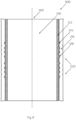
- Figures 6a-b schematically depict a cross sections of a tire 700 having grooves 720/720' in an inner surface 716 of a tread section 702 thereof.
- Grooves 720 are filled with a material different (e.g., more elastic or more compressible) than the surrounding material of inner surface 716. This material allows narrowing/widening of the grooves depending on the inflation pressure in tire 700.
- Fig. 6a depicts grooves 720 at a first inflation pressure
- Fig. 6b depicts grooves 720' at a second inflation pressure being lower than the first inflation pressure (as depicted by the hollow arrows), according to embodiments of the current invention.
- the filing material of the grooves is flexible (or compressible) enough that it allows the grooves to narrow (from configuration 720' to 720), and vice versa.
- tread section 102 is lifted from a road surface 706 in a desired manner dependent on the inflation pressure of tire 700.
- the side zones may be designed for increased loads while the central zone designed for unloaded drive.
- the side zones When higher pressure applied the side zones are lifted from the ground and the truck is in light weight driving mode.
- air pressure reduced the side zones are in contact with the ground and the truck is in full load driving mode.
- steel cords are typically incorporated into the tire as reinforcing elements. These cords run radially (from the tire beads) down the side wall and all the way around the tire.
- a truck typically has about 1200 cords in a tire.
- the steel cords and the tire rubber allow combination of strength and flexibility and thus help absorbing shock from uneven road surfaces.
- the radial (steel) cords may be made to assume the indentations which may be compatible to the tire circumferential grooves.
- Fig. 7a schematically depicts a cross section of a tire 800 having a reinforcing element 850, according to an embodiment of the current invention.
- Fig. 7b schematically depicts reinforcing element 850 of tire 800 of Fig. 7a , according to an embodiment of the current invention.
- Reinforcing element 850 is a cord (typically a metal, such as steel cord, configured to run radially down side wall 804 and all the way around tire 800.
- Reinforcing element 850 incudes indentations 860 (may also be referred to as bent or curved sections), which are configured to fit circumferential grooves 820 located in an inner surface 816 of a tread section 802 of tire 800. Reinforcing element 850 is essentially perpendicular to grooves (channels) 820.
- Tire building process typically includes assembling all the tire components onto a tire building drum.
- Tire-building machines can be manually operated or partially/fully automatic.
- Typical TBM operations include the first-stage operation, where inner liner, body plies, and sidewalls are wrapped around the drum, the beads are placed, and the assembly turned up over the bead.
- the carcass of the tire is inflated, then the belt package and tread are applied.
- the tire building drum e.g. a rotating drum
- the tire building drum includes one or more bulges at preselected location(s).
- TBM 900 includes a drum 910. During tire manufacturing, drum 910 may rotate around a longitudinal axis 905 thereof. An outer surface 912 of drum 910 includes a set of bulges, such as bulge 914.
- the tire plies 916 are laid on outer surface 912 of drum 910 such that grooves (channels/recesses) such as groove 918 are formed around the bulges (such as bulge 914).
- the tire section that includes the grooves is formed to be a tread section of the tire, having grooves at an inner section thereof.
- the term “high inflation pressure” may include an inflation pressure of about 30-40psi (207-276 kPa; for example, 33-35psi, 34-36psi, 32-37psi, etc.).
- the term “medium inflation pressure” may include an inflation pressure of about 20-30psi (138-207 kPa; for example, 20-25psi, 22-27psi, 25-28-37psi, etc.).
- the term “low inflation pressure” may include an inflation pressure of about 12-20 (83-138 kPa; for example, 13-15, 14-16psi, 15-17psi, 15-19psi, etc.).
- the "tread section" includes two opposing surfaces: an outer surface, designed to contact the road, an inner surface opposing to the outer surface and any layer that may be disposed between the two surfaces.
- the term “inner surface” of the tread section may include an inner liner, an under-tread layer, a cap plie, a belt (e.g., rubber, still, nylon or any other belt), carcass or any other layer or combination of layers.
- the "tread section" does not include the tire's side walls.
- channels(s) and “groove(s)” may be used interchangeably.
Landscapes
- Engineering & Computer Science (AREA)
- Mechanical Engineering (AREA)
- Tires In General (AREA)
Claims (14)
- Mehrzweckreifen, umfassend:einen Laufflächenabschnitt (102, 702, 802), welcher einen Hauptlaufflächenbereich (110, 210, 310, 410) und wenigstens einen Hilfslaufflächenbereich (112, 114, 212, 214, 312, 314, 412, 414) umfasst,wobei der Laufflächenabschnitt (102, 702, 802) dazu eingerichtet ist, bei einem ersten Fülldruck eine erste Laufflächenkonfiguration, wobei der wenigstens eine Hilfslaufflächenbereich (112, 114, 212, 214, 312, 314, 412, 414) eine Straßenoberfläche (106, 206, 306, 706) kontaktiert, und bei einem zweiten Fülldruck eine zweite Laufflächenkonfiguration zu erleichtern, wobei ein Kontakt des wenigstens einen Hilfslaufflächenbereichs (112, 114, 212, 214, 312, 314, 412, 414) mit der Straße verhindert oder reduziert ist, wobei der erste Fülldruck niedriger ist als der zweite Fülldruck, wobei der Laufflächenabschnitt (102, 702, 802) in einer inneren Fläche davon ferner einen oder mehrere Kanäle (120) umfasst, welche sich kontinuierlich in einer Umfangsrichtung des Reifens erstrecken, wobei der eine oder die mehreren Umfangskanäle (120) dazu eingerichtet sind, einen Fülldruck-abhängigen Übergang zwischen der ersten und der zweiten Laufflächenkonfiguration zu regulieren,dadurch gekennzeichnet, dass der Hauptlaufflächenbereich (110, 210, 310, 410) erste, radial äußere Oberflächenmerkmale umfasst und der wenigstens eine Hilfslaufflächenbereich (112, 114, 212, 214, 312, 314, 412, 414) zweite, äußere Oberflächenmerkmale umfasst, welche von den ersten, äußeren Oberflächenmerkmalen verschieden sind.
- Reifen nach Anspruch 1, wobei der eine oder die mehreren Kanäle (120) eine gemeinsame Struktur bilden, welche den Übergang zwischen der ersten und der zweiten Laufflächenkonfiguration erleichtert.
- Reifen nach Anspruch 1, wobei der eine oder die mehreren Kanäle (120) wenigstens teilweise eine Substanz enthalten, welche eine Elastizität aufweist, die höher ist als die Elastizität der inneren Fläche.
- Reifen nach Anspruch 1, wobei der eine oder die mehreren Kanäle (120) wenigstens teilweise eine Substanz enthalten, welche eine Komprimierbarkeit aufweist, die höher ist als die Komprimierbarkeit der inneren Fläche.
- Reifen nach Anspruch 1, wobei der Hauptlaufflächenbereich (110, 210, 310, 410) ein zentraler Bereich ist und der wenigstens eine Hilfslaufflächenbereich (112, 114, 212, 214, 312, 314, 412, 414) zwei seitliche Hilfsbereiche umfasst, welche an beiden Seiten des Hauptlaufflächenbereichs (110, 210, 310, 410) angeordnet sind.
- Reifen nach Anspruch 1, wobei die erste Konfiguration einen Volllast-Fahrmodus erleichtert und wobei die zweite Konfiguration einen Leichtgewicht-Fahrmodus erleichtert.
- Reifen nach Anspruch 1, wobei der Hauptlaufflächenbereich (110) ein erstes, radial äußeres Oberflächenmuster umfasst und der wenigstens eine Hilfslaufflächenbereich ein zweites, radial äußeres Oberflächenmuster umfasst, welches von dem ersten, radial äußeren Oberflächenmuster verschieden ist.
- Reifen nach Anspruch 7, wobei das erste, radial äußere Oberflächenmuster dazu eingerichtet ist, ein Fahren auf einer gepflasterten Straße zu erleichtern, und wobei das zweite, radial äußere Oberflächenmuster dazu eingerichtet ist, ein Fahren bei "Off Road"-Bedingungen zu erleichtern.
- Reifen nach Anspruch 7, wobei das erste, radial äußere Oberflächenmuster dazu eingerichtet ist, ein Fahren auf einer im Wesentlichen trockenen Straße zu erleichtern, und wobei das zweite, radial äußere Oberflächenmuster dazu eingerichtet ist, ein Fahren auf einer nassen, eisigen und/oder schneebedeckten Straße zu erleichtern.
- Reifen nach Anspruch 1, wobei die zweite, radial äußere Oberfläche (118) Spikes (415) umfasst, welche dazu eingerichtet sind, ein Fahren auf einer eisigen und/oder schneebedeckten Straße zu erleichtern.
- Reifen nach Anspruch 1, wobei die zweite Laufflächenkonfiguration einen ökonomischen Fahrmodus erleichtert und die erste Laufflächenkonfiguration einen Hochgeschwindigkeitsfahrmodus erleichtert.
- Reifen nach Anspruch 1, ferner umfassend ein oder mehrere Verstärkungselemente (850), welche sich radial von den Reifenwülsten, entlang der Seitenwand und um den Reifen herum erstrecken, wobei das eine oder die mehreren Verstärkungselemente im Wesentlichen senkrecht zu dem einen oder den mehreren Umfangskanälen (120) sind, wobei das eine oder die mehreren Verstärkungselemente (850) Vertiefungen an Stellen umfassen, welche zu dem einen oder den mehreren Umfangskanälen passen.
- Reifen nach Anspruch 12, wobei das eine oder die mehreren Verstärkungselemente einen oder mehrere Metallstränge umfassen.
- Reifen nach Anspruch 12, wobei das Reifenproduktionsmaterial eine Innenschicht, Unterbaulagen oder eine Kombination davon umfasst, wobei der eine oder die mehreren Umfangskanäle (120) wenigstens an der Innenschicht gebildet sind.
Applications Claiming Priority (2)
| Application Number | Priority Date | Filing Date | Title |
|---|---|---|---|
| IL253151A IL253151B (en) | 2017-06-25 | 2017-06-25 | Multipurpose tires |
| PCT/IL2018/050346 WO2019003215A1 (en) | 2017-06-25 | 2018-03-26 | VEHICLE TIRES |
Publications (4)
| Publication Number | Publication Date |
|---|---|
| EP3645313A1 EP3645313A1 (de) | 2020-05-06 |
| EP3645313A4 EP3645313A4 (de) | 2021-03-03 |
| EP3645313C0 EP3645313C0 (de) | 2023-06-07 |
| EP3645313B1 true EP3645313B1 (de) | 2023-06-07 |
Family
ID=62454793
Family Applications (1)
| Application Number | Title | Priority Date | Filing Date |
|---|---|---|---|
| EP18825292.8A Active EP3645313B1 (de) | 2017-06-25 | 2018-03-26 | Fahrzeugreifen |
Country Status (4)
| Country | Link |
|---|---|
| US (1) | US20200062039A1 (de) |
| EP (1) | EP3645313B1 (de) |
| IL (1) | IL253151B (de) |
| WO (1) | WO2019003215A1 (de) |
Family Cites Families (10)
| Publication number | Priority date | Publication date | Assignee | Title |
|---|---|---|---|---|
| US4027712A (en) * | 1973-12-21 | 1977-06-07 | Compagnie Generale Des Etablissements Michelin, Raison Sociale Michelin & Cie | Tire filled with lubricant coated cellular particles |
| IT1133894B (it) * | 1980-10-15 | 1986-07-24 | Pirelli | Miglioramenti nei procedimenti e nelle apparecchiature per la fabbricazione di pneumatici |
| JPH04334603A (ja) * | 1991-05-09 | 1992-11-20 | Bridgestone Corp | 空気入りタイヤ |
| US6923233B1 (en) * | 1999-09-30 | 2005-08-02 | The Goodyear Tire & Rubber Company | Runflat tire with sawtooth shaped insert |
| JP2001347810A (ja) * | 2000-06-07 | 2001-12-18 | Bridgestone Corp | 全路面対応型空気入りタイヤおよびその使用方法 |
| US20030024622A1 (en) | 2001-05-04 | 2003-02-06 | Chrobak Dennis S. | Anisotropic homogeneous elastomeric closed torus tire design & method of manufacture |
| WO2012090310A1 (ja) * | 2010-12-28 | 2012-07-05 | ソシエテ ド テクノロジー ミシュラン | 空気入りタイヤ |
| US20130030658A1 (en) * | 2011-07-27 | 2013-01-31 | Tom Dominique Linster | Adjustable tire pressure system and method |
| US20130153082A1 (en) * | 2011-12-14 | 2013-06-20 | International Business Machines Corporation | Variable friction tires |
| JP2013220718A (ja) * | 2012-04-16 | 2013-10-28 | Yokohama Rubber Co Ltd:The | 空気入りタイヤ |
-
2017
- 2017-06-25 IL IL253151A patent/IL253151B/en active IP Right Grant
-
2018
- 2018-03-26 EP EP18825292.8A patent/EP3645313B1/de active Active
- 2018-03-26 WO PCT/IL2018/050346 patent/WO2019003215A1/en not_active Ceased
- 2018-03-26 US US16/610,609 patent/US20200062039A1/en not_active Abandoned
Also Published As
| Publication number | Publication date |
|---|---|
| US20200062039A1 (en) | 2020-02-27 |
| IL253151A0 (en) | 2017-07-31 |
| EP3645313C0 (de) | 2023-06-07 |
| EP3645313A1 (de) | 2020-05-06 |
| WO2019003215A1 (en) | 2019-01-03 |
| EP3645313A4 (de) | 2021-03-03 |
| IL253151B (en) | 2018-05-31 |
Similar Documents
| Publication | Publication Date | Title |
|---|---|---|
| US5450885A (en) | Pneumatic tire including a tread with circumferential grooves | |
| KR100293800B1 (ko) | 안전 공기 타이어 | |
| JP5394057B2 (ja) | 空気入りタイヤ | |
| US7048022B2 (en) | Tire tread with anti-puncture pads | |
| US5427176A (en) | Pneumatic tire including at least one tie-element layer with substantially orthogonally oriented cords | |
| US20090194212A1 (en) | Tire tread discharge grooves with textured bases | |
| JP6189320B2 (ja) | 重量物運搬車両用タイヤの構造体とトレッドパターンの組み合わせ | |
| KR20120098472A (ko) | 공기 타이어 | |
| JP6032242B2 (ja) | 更生タイヤ | |
| US7617855B2 (en) | Pneumatic tire | |
| US5186772A (en) | Run-flat tire and rim assemblies for ATV | |
| EP1201464A2 (de) | Radiale Luftreifen | |
| CN107074039A (zh) | 充气轮胎 | |
| RU2441767C1 (ru) | Шипованная шина | |
| EP1428687A1 (de) | Luftreifen | |
| US20090194211A1 (en) | Tire tread grooves with textured bases | |
| EP0958153B1 (de) | Schwerlast-luftreifen mit spezifischer wulst-gestaltung | |
| CN101351345B (zh) | 重载车辆轮胎 | |
| US20090090449A1 (en) | Pneumatic tire | |
| EP3645313B1 (de) | Fahrzeugreifen | |
| US5343919A (en) | Pneumatic radial tire with specified belt curvature | |
| JP2003094913A (ja) | 冬用ランフラットタイヤ及びその製造方法 | |
| JP3238100B2 (ja) | 重荷重用タイヤ | |
| JPH1120405A (ja) | 空気入りタイヤ | |
| JP2002087019A (ja) | 空気入りタイヤ |
Legal Events
| Date | Code | Title | Description |
|---|---|---|---|
| STAA | Information on the status of an ep patent application or granted ep patent |
Free format text: STATUS: THE INTERNATIONAL PUBLICATION HAS BEEN MADE |
|
| PUAI | Public reference made under article 153(3) epc to a published international application that has entered the european phase |
Free format text: ORIGINAL CODE: 0009012 |
|
| STAA | Information on the status of an ep patent application or granted ep patent |
Free format text: STATUS: REQUEST FOR EXAMINATION WAS MADE |
|
| 17P | Request for examination filed |
Effective date: 20191223 |
|
| AK | Designated contracting states |
Kind code of ref document: A1 Designated state(s): AL AT BE BG CH CY CZ DE DK EE ES FI FR GB GR HR HU IE IS IT LI LT LU LV MC MK MT NL NO PL PT RO RS SE SI SK SM TR |
|
| AX | Request for extension of the european patent |
Extension state: BA ME |
|
| DAV | Request for validation of the european patent (deleted) | ||
| DAX | Request for extension of the european patent (deleted) | ||
| REG | Reference to a national code |
Ref country code: DE Ref legal event code: R079 Ref document number: 602018051414 Country of ref document: DE Free format text: PREVIOUS MAIN CLASS: B60C0005000000 Ipc: B60C0011000000 |
|
| A4 | Supplementary search report drawn up and despatched |
Effective date: 20210128 |
|
| RIC1 | Information provided on ipc code assigned before grant |
Ipc: B60C 11/14 20060101ALI20210122BHEP Ipc: B60C 11/00 20060101AFI20210122BHEP Ipc: B60C 11/04 20060101ALI20210122BHEP |
|
| GRAP | Despatch of communication of intention to grant a patent |
Free format text: ORIGINAL CODE: EPIDOSNIGR1 |
|
| STAA | Information on the status of an ep patent application or granted ep patent |
Free format text: STATUS: GRANT OF PATENT IS INTENDED |
|
| INTG | Intention to grant announced |
Effective date: 20221007 |
|
| GRAS | Grant fee paid |
Free format text: ORIGINAL CODE: EPIDOSNIGR3 |
|
| GRAA | (expected) grant |
Free format text: ORIGINAL CODE: 0009210 |
|
| STAA | Information on the status of an ep patent application or granted ep patent |
Free format text: STATUS: THE PATENT HAS BEEN GRANTED |
|
| AK | Designated contracting states |
Kind code of ref document: B1 Designated state(s): AL AT BE BG CH CY CZ DE DK EE ES FI FR GB GR HR HU IE IS IT LI LT LU LV MC MK MT NL NO PL PT RO RS SE SI SK SM TR |
|
| REG | Reference to a national code |
Ref country code: GB Ref legal event code: FG4D |
|
| REG | Reference to a national code |
Ref country code: CH Ref legal event code: EP Ref country code: AT Ref legal event code: REF Ref document number: 1573944 Country of ref document: AT Kind code of ref document: T Effective date: 20230615 |
|
| REG | Reference to a national code |
Ref country code: DE Ref legal event code: R096 Ref document number: 602018051414 Country of ref document: DE |
|
| U01 | Request for unitary effect filed |
Effective date: 20230705 |
|
| U07 | Unitary effect registered |
Designated state(s): AT BE BG DE DK EE FI FR IT LT LU LV MT NL PT SE SI Effective date: 20230714 |
|
| REG | Reference to a national code |
Ref country code: LT Ref legal event code: MG9D |
|
| PG25 | Lapsed in a contracting state [announced via postgrant information from national office to epo] |
Ref country code: NO Free format text: LAPSE BECAUSE OF FAILURE TO SUBMIT A TRANSLATION OF THE DESCRIPTION OR TO PAY THE FEE WITHIN THE PRESCRIBED TIME-LIMIT Effective date: 20230907 Ref country code: ES Free format text: LAPSE BECAUSE OF FAILURE TO SUBMIT A TRANSLATION OF THE DESCRIPTION OR TO PAY THE FEE WITHIN THE PRESCRIBED TIME-LIMIT Effective date: 20230607 |
|
| PG25 | Lapsed in a contracting state [announced via postgrant information from national office to epo] |
Ref country code: RS Free format text: LAPSE BECAUSE OF FAILURE TO SUBMIT A TRANSLATION OF THE DESCRIPTION OR TO PAY THE FEE WITHIN THE PRESCRIBED TIME-LIMIT Effective date: 20230607 Ref country code: HR Free format text: LAPSE BECAUSE OF FAILURE TO SUBMIT A TRANSLATION OF THE DESCRIPTION OR TO PAY THE FEE WITHIN THE PRESCRIBED TIME-LIMIT Effective date: 20230607 Ref country code: GR Free format text: LAPSE BECAUSE OF FAILURE TO SUBMIT A TRANSLATION OF THE DESCRIPTION OR TO PAY THE FEE WITHIN THE PRESCRIBED TIME-LIMIT Effective date: 20230908 |
|
| PG25 | Lapsed in a contracting state [announced via postgrant information from national office to epo] |
Ref country code: SK Free format text: LAPSE BECAUSE OF FAILURE TO SUBMIT A TRANSLATION OF THE DESCRIPTION OR TO PAY THE FEE WITHIN THE PRESCRIBED TIME-LIMIT Effective date: 20230607 |
|
| PG25 | Lapsed in a contracting state [announced via postgrant information from national office to epo] |
Ref country code: IS Free format text: LAPSE BECAUSE OF FAILURE TO SUBMIT A TRANSLATION OF THE DESCRIPTION OR TO PAY THE FEE WITHIN THE PRESCRIBED TIME-LIMIT Effective date: 20231007 |
|
| PG25 | Lapsed in a contracting state [announced via postgrant information from national office to epo] |
Ref country code: SM Free format text: LAPSE BECAUSE OF FAILURE TO SUBMIT A TRANSLATION OF THE DESCRIPTION OR TO PAY THE FEE WITHIN THE PRESCRIBED TIME-LIMIT Effective date: 20230607 Ref country code: SK Free format text: LAPSE BECAUSE OF FAILURE TO SUBMIT A TRANSLATION OF THE DESCRIPTION OR TO PAY THE FEE WITHIN THE PRESCRIBED TIME-LIMIT Effective date: 20230607 Ref country code: RO Free format text: LAPSE BECAUSE OF FAILURE TO SUBMIT A TRANSLATION OF THE DESCRIPTION OR TO PAY THE FEE WITHIN THE PRESCRIBED TIME-LIMIT Effective date: 20230607 Ref country code: IS Free format text: LAPSE BECAUSE OF FAILURE TO SUBMIT A TRANSLATION OF THE DESCRIPTION OR TO PAY THE FEE WITHIN THE PRESCRIBED TIME-LIMIT Effective date: 20231007 Ref country code: CZ Free format text: LAPSE BECAUSE OF FAILURE TO SUBMIT A TRANSLATION OF THE DESCRIPTION OR TO PAY THE FEE WITHIN THE PRESCRIBED TIME-LIMIT Effective date: 20230607 |
|
| PG25 | Lapsed in a contracting state [announced via postgrant information from national office to epo] |
Ref country code: PL Free format text: LAPSE BECAUSE OF FAILURE TO SUBMIT A TRANSLATION OF THE DESCRIPTION OR TO PAY THE FEE WITHIN THE PRESCRIBED TIME-LIMIT Effective date: 20230607 |
|
| REG | Reference to a national code |
Ref country code: DE Ref legal event code: R097 Ref document number: 602018051414 Country of ref document: DE |
|
| PLBE | No opposition filed within time limit |
Free format text: ORIGINAL CODE: 0009261 |
|
| STAA | Information on the status of an ep patent application or granted ep patent |
Free format text: STATUS: NO OPPOSITION FILED WITHIN TIME LIMIT |
|
| U20 | Renewal fee for the european patent with unitary effect paid |
Year of fee payment: 7 Effective date: 20240325 |
|
| 26N | No opposition filed |
Effective date: 20240308 |
|
| REG | Reference to a national code |
Ref country code: CH Ref legal event code: PL |
|
| PG25 | Lapsed in a contracting state [announced via postgrant information from national office to epo] |
Ref country code: MC Free format text: LAPSE BECAUSE OF FAILURE TO SUBMIT A TRANSLATION OF THE DESCRIPTION OR TO PAY THE FEE WITHIN THE PRESCRIBED TIME-LIMIT Effective date: 20230607 |
|
| PG25 | Lapsed in a contracting state [announced via postgrant information from national office to epo] |
Ref country code: MC Free format text: LAPSE BECAUSE OF FAILURE TO SUBMIT A TRANSLATION OF THE DESCRIPTION OR TO PAY THE FEE WITHIN THE PRESCRIBED TIME-LIMIT Effective date: 20230607 |
|
| PG25 | Lapsed in a contracting state [announced via postgrant information from national office to epo] |
Ref country code: IE Free format text: LAPSE BECAUSE OF NON-PAYMENT OF DUE FEES Effective date: 20240326 |
|
| PG25 | Lapsed in a contracting state [announced via postgrant information from national office to epo] |
Ref country code: IE Free format text: LAPSE BECAUSE OF NON-PAYMENT OF DUE FEES Effective date: 20240326 Ref country code: CH Free format text: LAPSE BECAUSE OF NON-PAYMENT OF DUE FEES Effective date: 20240331 |
|
| U20 | Renewal fee for the european patent with unitary effect paid |
Year of fee payment: 8 Effective date: 20250304 |
|
| PGFP | Annual fee paid to national office [announced via postgrant information from national office to epo] |
Ref country code: GB Payment date: 20250301 Year of fee payment: 8 |
|
| PG25 | Lapsed in a contracting state [announced via postgrant information from national office to epo] |
Ref country code: CY Free format text: LAPSE BECAUSE OF FAILURE TO SUBMIT A TRANSLATION OF THE DESCRIPTION OR TO PAY THE FEE WITHIN THE PRESCRIBED TIME-LIMIT; INVALID AB INITIO Effective date: 20180326 |
|
| PG25 | Lapsed in a contracting state [announced via postgrant information from national office to epo] |
Ref country code: HU Free format text: LAPSE BECAUSE OF FAILURE TO SUBMIT A TRANSLATION OF THE DESCRIPTION OR TO PAY THE FEE WITHIN THE PRESCRIBED TIME-LIMIT; INVALID AB INITIO Effective date: 20180326 |
|
| PG25 | Lapsed in a contracting state [announced via postgrant information from national office to epo] |
Ref country code: TR Free format text: LAPSE BECAUSE OF FAILURE TO SUBMIT A TRANSLATION OF THE DESCRIPTION OR TO PAY THE FEE WITHIN THE PRESCRIBED TIME-LIMIT Effective date: 20230607 |