EP3644909B1 - Griff zur freisetzung eines stents und vorrichtung mit dem griff - Google Patents
Griff zur freisetzung eines stents und vorrichtung mit dem griff Download PDFInfo
- Publication number
- EP3644909B1 EP3644909B1 EP18749453.9A EP18749453A EP3644909B1 EP 3644909 B1 EP3644909 B1 EP 3644909B1 EP 18749453 A EP18749453 A EP 18749453A EP 3644909 B1 EP3644909 B1 EP 3644909B1
- Authority
- EP
- European Patent Office
- Prior art keywords
- handle
- stent
- tubular element
- distal end
- sheath
- Prior art date
- Legal status (The legal status is an assumption and is not a legal conclusion. Google has not performed a legal analysis and makes no representation as to the accuracy of the status listed.)
- Active
Links
Images


Classifications
-
- A—HUMAN NECESSITIES
- A61—MEDICAL OR VETERINARY SCIENCE; HYGIENE
- A61F—FILTERS IMPLANTABLE INTO BLOOD VESSELS; PROSTHESES; DEVICES PROVIDING PATENCY TO, OR PREVENTING COLLAPSING OF, TUBULAR STRUCTURES OF THE BODY, e.g. STENTS; ORTHOPAEDIC, NURSING OR CONTRACEPTIVE DEVICES; FOMENTATION; TREATMENT OR PROTECTION OF EYES OR EARS; BANDAGES, DRESSINGS OR ABSORBENT PADS; FIRST-AID KITS
- A61F2/00—Filters implantable into blood vessels; Prostheses, i.e. artificial substitutes or replacements for parts of the body; Appliances for connecting them with the body; Devices providing patency to, or preventing collapsing of, tubular structures of the body, e.g. stents
- A61F2/95—Instruments specially adapted for placement or removal of stents or stent-grafts
- A61F2/9517—Instruments specially adapted for placement or removal of stents or stent-grafts handle assemblies therefor
-
- A—HUMAN NECESSITIES
- A61—MEDICAL OR VETERINARY SCIENCE; HYGIENE
- A61F—FILTERS IMPLANTABLE INTO BLOOD VESSELS; PROSTHESES; DEVICES PROVIDING PATENCY TO, OR PREVENTING COLLAPSING OF, TUBULAR STRUCTURES OF THE BODY, e.g. STENTS; ORTHOPAEDIC, NURSING OR CONTRACEPTIVE DEVICES; FOMENTATION; TREATMENT OR PROTECTION OF EYES OR EARS; BANDAGES, DRESSINGS OR ABSORBENT PADS; FIRST-AID KITS
- A61F2/00—Filters implantable into blood vessels; Prostheses, i.e. artificial substitutes or replacements for parts of the body; Appliances for connecting them with the body; Devices providing patency to, or preventing collapsing of, tubular structures of the body, e.g. stents
- A61F2/95—Instruments specially adapted for placement or removal of stents or stent-grafts
- A61F2/962—Instruments specially adapted for placement or removal of stents or stent-grafts having an outer sleeve
- A61F2/966—Instruments specially adapted for placement or removal of stents or stent-grafts having an outer sleeve with relative longitudinal movement between outer sleeve and prosthesis, e.g. using a push rod
Definitions
- a handle for stent delivery and a stent delivery device comprising the handle are disclosed.
- the invention also relates to a method of delivering the Stent with said handle.
- a stent delivery device comprising a handle 212 which includes a housing 214 and a pulley 222, a push rod 204 having a proximal end 204P connected to the housing and a distal end adjacent to which the stent is located and in which the handle has a linear length Y shorter than the linear length X of the stent.
- a sheath 206 for constricting the stent at its distal portion and having a proximal end 206P connected to a distal end of a retraction wire 224 connected at its proximal end to said pulley 222.
- this device has the drawback of requiring a significant retraction force to be exerted on the pulley in order to proceed with the withdrawal of the constriction sheath from the stent.
- Document D1 US 2007/0168014 describes a handle for delivering a stent comprising a system for pulling the protective sheath and constricting the stent with pulling cords 180, see FIGS. 15A, 15B, 15C, one front end of which is fixed to a movable element called SLIDER 152 which is common to all the embodiments, since it is this which is connected to the protective sheath of the stent and serves to pull the sheath during its movement.
- SLIDER 152 movable element
- the invention provides a handle of simple design as described below.
- the main object of the invention is to find a solution which solves the technical problem of reducing the tensile force which must be exerted on the pulley to lead to the withdrawal of the sheath and to release the stent at the distal end.
- Another main aim of the invention is to find a solution which solves the technical problem of reducing the tensile force which must be exerted on the pulley according to a solution which multiplies this tensile force.
- Another main object of the invention is to find a solution which solves the technical problem of reducing the tensile force that must be exerted on the pulley, which is simple to use, without increasing the manufacturing cost and which is technically and medically safe and reliable, allowing manufacturing on an industrial scale.
- the invention provides a handle for delivery of a stent disposed on a catheter by movement of withdrawal of a tubular member or so-called intermediate sheath, protecting the stent, having a distal end and a proximal end, the stent is arranged in such a manner.
- the hoist system comprises upstream a loop integral with the tubular element or sheath called intermediate protection in which loop passes a wire having a hoist function, one end of which is fixed to the housing of the handle to be fixed and the other end is integral with a maneuvering wheel rotatably mounted on the housing of the handle.
- the handle has a front part in the direction of the stent and a rear part serving to introduction of the catheter on which the stent is placed, in the initial position, the hoist system is towards the front of the handle so that when withdrawing, by traction, the withdrawal distance is of a substantially close length the length of the handle.
- the aforementioned roller comprises a bearing or lateral shaft on which the traction wire is wound.
- the caster with its lateral bearing or shaft is in an intermediate position between the front and the rear of the handle, the rear part of the handle being of a size allowing to be held comfortably in the hand of an operator.
- the operator can firmly hold the handle while being able to maneuver the caster which is of sufficient size to have its outer circumferential edge protruding outside the handle.
- the circumferential outer edge of the handle is notched in order to facilitate the operation of rotation exerted by an operator's finger which may be the thumb when the wheel is placed at the top of the handle.
- a support pin for returning the traction wire coming from the front part of the handle passing through the loop, which also contributes to reducing the tensile force that must be exerted on the sheath in order to pull it inside the handle.
- the pull wire is attached at a first end to a base integral with the housing towards the rear part of the handle, then goes to the front of the handle to pass through the loop integral with the protective sheath of the stent, returns to the rear of the handle to pass around the axis support and return, and moves forward until its second end is attached to the wheel.
- the total length of the pulling wire is greater than twice the length of the handle and less than three times the length of the handle.
- the return support pin arranged at the rear of the handle may be made of a material facilitating sliding, such as metal or plastic.
- the handle has at the front a reinforcing element serving to stiffen it and to connect with the catheter device comprising the stent.
- a provisional blocking element is provided for movement of the hoist system.
- This locking element can be provided at the level of the wheel by preventing its rotation and in particular provided at the level of the loop integral with the tubular element or intermediate sheath, by being introduced under the loop, for example in the form of a tab. of cylindrical or frustoconical section, in order to lift the loop, and crush it to lock it in position until the time of the operation of the handle.
- the invention also covers a system for delivering a stent which comprises the handle described above.
- this system for delivering the stent comprises the aforementioned handle and a catheter device, shaped to be introduced into a channel of the human body, in particular a blood vessel, a vein, an artery and in particular a coronary, and comprising a tubular element or so-called intermediate sheath having a proximal end and a distal end; a stent constrainedly disposed within the distal end of the intermediate tubular member; a tubular element or so-called inner sheath, having a proximal end and a distal end, arranged inside the said intermediate tubular element and having a sufficient length so that its distal end comes to be positioned behind the stent and the lock in position, to prevent its removal; the proximal end of the internal tubular element is secured to the handle to have a fixed position.
- a so-called external tubular element or sheath having a proximal end and a distal end, which is positioned outside the intermediate tubular element, of a dimension shorter than the intermediate tubular element to have its distal end disposed at a predetermined distance upstream of the stent, the proximal end of the outer tubular element is secured to the handle to also have a fixed position.
- the distal end of the intermediate tubular element has a larger diameter D1 over the entire length where it receives the stent to facilitate its insertion, then has a junction slope to end in a smaller diameter D2 on the upstream part of the intermediate tubular element.
- This diameter D1 is designed to correspond substantially to the diameter D3 of the outer tubular element so as to be positioned against the distal end of the outer tubular element which is fixed and which constitutes a stopper for stopping the withdrawal of the intermediate tubular element .
- the intermediate tubular element is designed to slide longitudinally between the inner tubular element and the outer tubular element which remain in a fixed position relative to the handle; the stent remaining in place because the position of the distal end of the inner tubular member remains fixed and prevents any withdrawal movement of the stent.
- the invention therefore makes it possible to deliver the stent to a precise position.
- the predetermined distance upstream of the stent from the distal end of the so-called outer tubular element or sheath may correspond substantially to the withdrawal distance of the intermediate tubular element, this withdrawal distance corresponding at least to the length of the stent to be delivered.
- the invention relates to a new concept of handle (10) for delivery of a stent (2) by movement of withdrawal of a tubular element or sheath (120) protecting the stent (2), this element or sheath can be intermediate according to the presently preferred embodiment and forms part of a catheter (100) which will be described later.
- a tubular element (110) for blocking or stopping the stent (2) called “push tubing” or “stop tubing” and advantageously an outer tubular element or outer sheath (130) facilitating the introduction into a. channel such as a blood vessel.
- the terms “tubular element” or “sheath” will be used interchangeably.
- This presently preferred embodiment also relates to a system for delivering a stent (2) which comprises this handle (10) which constitutes the essence of the invention.
- the stent delivery system generally includes a catheter device (100) designed to allow a predetermined withdrawal distance D defined in part by the length of the handle (10), to uncover the stent (2) and allow its delivery. and its expansion. It is easily understood that the predetermined withdrawal distance D is also a function of the length of the stent (2) to be released. The lengths of the stent (2) to be released are variable and can reach 150mm or even 200mm. It is easily understood that one can provide several dimensions of handles to adapt to the length of the stent (2).
- the handle is characterized in that it comprises a hoist system (20) serving to pull the intermediate protective sheath (120) of the stent (2) over a predetermined withdrawal distance (D) in order to to uncover the stent and allow its delivery and expansion.
- a hoist system (20) serving to pull the intermediate protective sheath (120) of the stent (2) over a predetermined withdrawal distance (D) in order to to uncover the stent and allow its delivery and expansion.
- the handle is characterized in that the hoist system (20) comprises a loop (30) integral with the intermediate protective sheath (120) upstream by having the two legs of the loop secured to the protective sheath (120).
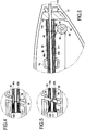
- This loop (30) and its attachment to the intermediate sheath (120) are clearly visible in enlarged figures 3, 4 and 5.
- a traction wire (40) having a function. hoist, one end (40a) of which is fixed to the housing or shell here left (12) of the handle (10) to be fixed and the other end (40b) is secured to a roller maneuver (50) rotatably mounted on the casing or shell (12) of the handle.
- the handle (10) has a front part (12a) here on the shell (12) in the direction of the stent (2) and a rear part (12b), provided with a cannula (112). , used for the introduction of a guide wire, not shown here, passing through the central channel (111).
- the hoist system (20) is located towards the front (12a) of the handle (10) so that when withdrawing, by pulling, the withdrawal distance (D) is of a length substantially close to the length of the handle, this length itself being calculated in correspondence with the length of the stent (2).
- the wheel (50) comprises a lateral shaft (60) on which the traction wire (40) is wound.
- the wheel (50) with its lateral shaft (60) is located in an intermediate position between the front (12a) and the rear (12b) of the handle (10), the handle ( 10) being of a size to be comfortably held in the hand of an operator.
- the operator can firmly hold the handle (10) while being able to maneuver the caster (50).
- the caster (50) is mounted on an axis of rotation (51) positioned so that the outer circumferential edge of the caster (50) protrudes outside of the handle (10), passing through an opening (70) provided for this purpose in the housing.
- the outer circumferential edge of the roller (50) is notched with notches (52), in order to facilitate the operation of rotation exerted by an operator's finger which may be the thumb when the wheel (50) is positioned on the upper part of the handle (10), as shown.
- it can also also be provided at the level of the roller (50) the presence of a non-return blade (94) of the roller co-operating with teeth (53) provided in an axial housing of the roller ( 50), by preventing its inadvertent rotation during the insertion of the catheter (100), as clearly visible at the figure 7 .
- the return support axis (82) disposed at the rear of the handle comprises a spacer (84) integral with the support axis (82).
- the handle can also have at the rear a transverse reinforcing element (13) comprising a through orifice defining a continuity with the central channel (111), see figure 6 .
- the handle (10) has at the front (12a) a hollow reinforcing element (18) through which the catheter (100) passes, avoiding the catheter device (100) comprising the stent (2) to fold.
- the reinforcing element (18) has, according to an alternative embodiment shown in particular in figure 3 , in a very enlarged manner, a frustoconical front part arranged outside the handle and a rear part in the shape of an inverted T whose base of the T is housed in a transverse housing where it is held firmly in the closed position of the handle .
- an element (90) is provided for temporarily blocking an untimely movement of the hoist system (20).
- the locking element (90) such as a pin having an orifice (91) for the passage of a finger to pull it, may be provided at the level of the loop (30) to be for example introduced under the loop (30), and present for example a cylindrical (92) or frustoconical tab, in order to lift it, and crush it to lock it in position until the moment of the operation of the handle (10 ).
- the locking element (90) here advantageously has a second tab (93) which is inserted between two teeth (52) of the wheel (50), which also prevents it from turning inadvertently.
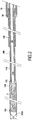
- the invention also relates to a system for delivering a stent (2) positioned on a catheter (100), better shown in FIGS. figures 1 and 2 , characterized in that it comprises a handle (10) as defined above.
- the System is characterized in that the catheter (100) comprises a distal end (100a) comprising the stent (2) to be delivered and a proximal end (100b), and is shaped to be introduced into a channel of the human body, in particular a blood vessel, a vein, an artery and a peripheral application; comprising a so-called intermediate tubular or sheath (120) having a proximal end and a distal end; a stent (2) constrainedly disposed within the distal end of the intermediate tubular member (120); a tubular element or so-called inner sheath (110), having a proximal end and a distal end, arranged inside the said intermediate tubular element (120) and having a sufficient length so that its distal end comes to be positioned at the back of the stent and lock it in position, to prevent its removal, as seen at figure 2 ; the proximal end of the internal tubular element (110) is secured to the handle (10) to have
- a so-called external tubular element or sheath having a proximal end and a distal end, which is positioned outside the intermediate tubular element (120 ), of a dimension shorter than the intermediate tubular element to have its distal end disposed at a predetermined distance upstream of the stent, as shown, the proximal end of the outer tubular element (130) is secured to the handle (10) to also have a fixed position.
- the distal end of the intermediate tubular element (120) has a larger diameter D1 over at least the entire length where it receives the stent (2) to facilitate its insertion, then presents a junction slope to result in a diameter D2 smaller than the rest of the intermediate tubular element, as shown in figure 2 .
- This diameter D1 is expected to correspond substantially to the diameter D3 of the outer tubular element (130) so as to be positioned against the distal end of the outer tubular element which is fixed and which constitutes a stopper for stopping the withdrawal of the intermediate tubular element.
- a tubular element (38) which can be provided transparent which serves as a guide for the movement of the movable elements such as the intermediate sheath (120) and the traction wire (40). .
- the intermediate tubular element (120) is designed to slide longitudinally between the inner tubular element (110) and the outer tubular element (130) which remain in a fixed position relative to the handle. (10) by being integral with it; the stent (2) remaining in place because the position of the distal end of the inner tubular member (110) remains fixed and prevents any withdrawal movement of the stent.
- the invention therefore makes it possible to deliver the stent (2) to a precise position.
- the surgeon or the operator can correct at the level of the introducer, not shown here, any unwanted movement of the so-called intermediate tubular element (120) or protective sheath of the stent (2 ) in the channel such as a blood vessel of the patient which could cause deployment of the implant or stent (2) outside the site of the stenosis.
- the surgeon or the operator can correct at the level of the introducer, not shown here, any unwanted movement of the so-called intermediate tubular element (120) or protective sheath of the stent (2 ) in the channel such as a blood vessel of the patient which could cause deployment of the implant or stent (2) outside the site of the stenosis.
- he can, once the locking element (90) has been removed, forming a safety pin, to act in rotation on the caster (50) in order to release the stent (2).
- position markers for example a distal marker (160) at the front end 100a of the catheter, here on the intermediate tubular element (120); a distal marker (170) at the front end of the inner tubular member (110) coming to the rear of the stent (2) to prevent removal of the stent.
- a distal marker (160) at the front end 100a of the catheter here on the intermediate tubular element (120); a distal marker (170) at the front end of the inner tubular member (110) coming to the rear of the stent (2) to prevent removal of the stent.
- the position of the stent (2) is perfectly marked for the practitioner.
- the catheter (100) is then slid through its internal channel (111) over the guidewire and inserted into the introducer to advance to the stent delivery site (2), the stent advancement position ( 2) being identified by markers (160) and (170).
- the catheter (100) is advantageously flushed with a water / contrast liquid mixture in order to evacuate any trace of air from the interior of the catheter comprising the elements or sheaths respectively internal (110), intermediate ( 120) supporting the implant or stent (2) and providing its protection from the stent, and external (130) facilitating the introduction of the catheter.
- distal end (100a) of the catheter (100) is engaged on the guidewire through the introducer in order to join the future implantation site.
- the operator then checks the location of the stenosis by injecting a mixture of contrast product into the arterial tree visible on the fluoroscopy in order to position the implant or stent (2) at the site of the stenosis.
- This implant or stent (2) is intended to be implanted in the peripheral arteries, at the location where there are stenoses (reduction in the diameter of the artery).
- the preferred locations are the extremities of the limbs of the human body, in particular the legs, which may suffer from poor irrigation, behind the knees, etc.
- the implant or stent (2) must be flexible to absorb any flexion, torsion, etc. created by natural mobilization of the limbs.
- a shape memory material for example nitinol
- nitinol nitinol
- a 7mm diameter stent will be implanted in the stenosis of an artery whose diameters upstream and downstream of the stenosis are approximately 6mm.
- the implant will therefore be perfectly affixed to the wall and thus maintained in the arterial flow by the counterpressure thereof.
- the handle (10) is formed of two complementary main parts or straight shells (11) visible at the figure 1 and left (12) visible on the figures 3 to 8 .
- the shape of the left and right shells has been designed so that the surgeon can manipulate the handle with ease and ease.
- the size of the handle is relatively small so as not to have too massive a device and too bulky packaging while ensuring sufficient retraction of the intermediate element or sheath regardless of the stent in the range.
- the reinforcement (18) is located at the front end of the handle (10), its role is to prevent the sheaths from flexing following sometimes brutal handling by operators who seek to position the stent correctly at the level of the stenosis. .
- the reinforcement is flexible while being strong enough to play its protective role.
- the wire (40) attached to the roller (50) has the possibility of winding around, in particular here around its lateral shaft (60) when the surgeon decides to release the stent (2) by rotating it.
- the roller (50) tightens the wire (40) which passes through the loop (30) of the tubular element or intermediate sheath (120).
- the wire (40) being fixed at its other end (40a), the system perfectly describes a hoist.
- This structure halves the tensile force required to remove the tubular member or intermediate sheath (120).
- the diameters of the caster (50) and side shaft (60) have been optimized to facilitate release of the stent (2): wire winding diameter (40) and overall caster diameter (50 ), where the notches (52) are located.
- the notches (52) have been designed so as not to have a too aggressive shape for the operator's gloves while giving him sufficient grip not to rip.
- a non-return ratchet system (94) for example a flexible blade such as a stack blade, prevents reverse movement of the caster (50).
- Wedge 78 Its role is minimal but allows easy positioning of the various components inside the handle during assembly.
- the base (80) is located in the extension of the internal tubular element 110 also called “push tubing” or “stop tubing” which is itself glued inside the base (80).
- the base (80) and the inner tubular member (110) allow the guidewire to pass through the central channel (111) along the entire length of the delivery system including the catheter (100).
- the wire (40) of the hoist (20) is also fixed to the base (80) inside thereof.
- the hoist system (20) makes it possible to halve the force exerted by the operator on the roller (50) in order to push back or pull the element or intermediate sheath (120).
- the loop (30) glued to the base of the element or intermediate sheath (120) acts as a "pulley" in which the withdrawal wire (40), connected on the one hand to the housing or here to the base secured to the housing which constitutes a fixed point, and on the other hand to the wheel (50) which constitutes a movable point, slides.
Claims (15)
- Griff (10) zur Freisetzung eines Stents (2) durch Entnahmebewegung eines röhrenförmigen oder umhüllenden Schutzelements (120) des Stents (2), umfassend ein Hebesystem (20), das dem Zug der Schutzhülle (120) über eine Entnahmestrecke (D) dient, die vorbestimmt ist, um den Stent aufzudecken und seine Freisetzung und seine Dilatation zuzulassen, dadurch gekennzeichnet, dass das Hebesystem (20) eine Schleife (30) umfasst, die einstückig mit der Schutzhülle (120) vorgelagert ist, in der ein Zugdraht (40) durchläuft, der eine Hebefunktion aufweist, wobei ein Ende (40a) an dem Gehäuse (11) des Griffes (10) befestigt ist, um fest zu sein, und das andere Ende (40b) einstückig mit einer Betätigungsrolle (50) ist, die drehbar auf dem Gehäuse (11) des Griffes montiert ist.
- Griff nach Anspruch 1, dadurch gekennzeichnet, dass der Griff (10) einen vorderen Teil (12a) in Richtung des Stents (2) und einen hinteren Teil (12b) aufweist, welcher der Einführung eines Katheters (100) dient, auf dem der Stent (2) montiert ist, wobei sich das Hebesystem (20) in Ausgangsposition zu der Vorderseite (12a) des Griffes hin befindet, sodass während der Entnahme durch Zug die Entnahmestrecke (D) eine Länge aufweist, die im Wesentlichen nahe der Länge des Griffes ist, wobei diese Länge selbst in Übereinstimmung mit der Länge des Stents (2) berechnet ist.
- Griff nach einem der Ansprüche 1 oder 2, dadurch gekennzeichnet, dass die vorstehend genannte Rolle (50) eine Seitenwelle (60) umfasst, auf der sich der Zugdraht (40) einrollt.
- Griff nach Anspruch 3, dadurch gekennzeichnet, dass sich die Rolle (50) mit ihrer Seitenwelle (60) in einer Zwischenposition zwischen der Vorderseite (12a) und der Rückseite (12b) des Griffes (10) befindet, wobei der hintere Teil (12b) des Griffes (10) eine Abmessung aufweist, die ein komfortables Halten in der Hand eines Bedieners zulässt.
- Griff nach einem der Ansprüche 1 bis 4, dadurch gekennzeichnet, dass die Rolle (50) auf einer Drehachse (51) montiert ist, die positioniert ist, um zu erreichen, dass der äußere Umfangsrand der Rolle (50) aus dem Äußeren des Griffes (10) herausragt, während er eine Öffnung (70) durchläuft, die zu diesem Zweck in dem Gehäuse vorgesehen ist.
- Griff nach Anspruch 5, dadurch gekennzeichnet, dass der äußere Umfangsrand der Rolle (50) gewellt ist, indem er Rastungen (52) aufweist, um den Betrieb der Drehung zu erleichtern, der durch einen Finger des Betreibers ausgeübt wird, welcher der Daumen sein kann.
- Griff nach einem der Ansprüche 1 bis 6, dadurch gekennzeichnet, dass im Inneren und an der Rückseite (12b) des Griffes (10) eine Stützachse (82) zur Rückführung des Zugdrahtes (40) vorgesehen ist, die von dem vorderen Teil (12a) des Griffes (10) ausgeht und die Schleife (30) durchläuft, was auch zum Reduzieren der Zugkraft, die auf die Schutzhülle (120) ausgeübt werden muss, um sie in das Innere des Griffes (10) zu ziehen, beiträgt.
- Griff nach Anspruch 7, dadurch gekennzeichnet, dass die Stützachse (82) zur Rückführung, die hinter dem Griff angeordnet ist, einen Abstandshalter (84) umfasst, der einstückig mit der Stützachse (82) ist.
- Griff nach einem der Ansprüche 1 bis 8, dadurch gekennzeichnet, dass der Griff (10) auf der Vorderseite (10a) ein hohles Verstärkungselement (18) aufweist, in dem der Katheter (100) verläuft, wodurch verhindert wird, dass die Kathetervorrichtung (100), die den Stent (2) umfasst, sich abbindet.
- Griff nach einem der Ansprüche 1 bis 9, dadurch gekennzeichnet, dass ein provisorisches Blockierungselement (90) zur Verschiebung des Hebesystems (20) vorgesehen ist.
- Griff nach Anspruch 10, dadurch gekennzeichnet, dass das Blockierungselement (90) auf Höhe der Schleife (30) vorgesehen sein kann, um zum Beispiel unter die Schleife (30) eingeführt zu werden, und zum Beispiel ein zylindrisches (92) oder kegelstumpfförmiges Muster aufweisen kann, um sie anzuheben, und sie zu zerdrücken, um sie genau in dem Moment der Betätigung des Griffes (10) in Position zu blockieren, und vorteilhafterweise auch auf Höhe der Rolle (50), indem ihre Drehung verhindert wird.
- System (1) zur Freisetzung eines Stents (2), der auf einem Katheter (100) positioniert ist, dadurch gekennzeichnet, dass es einen Griff (10) wie in einem der vorhergehenden Ansprüche definiert umfasst.
- System nach Anspruch 12, dadurch gekennzeichnet, dass der Katheter (100) ein distales Ende (100a), das den freizusetzenden Stent (2) umfasst, und ein proximales Ende (100b) umfasst und ausgebildet ist, um in einen menschlichen Körperkanal eingeführt zu werden, insbesondere ein Blutgefäß, eine Vene, eine periphere Arterie, wobei der Katheter (100) ein röhrenförmiges oder umhüllendes Element umfasst, das als Zwischenelement (120) bezeichnet wird, das ein proximales Ende und ein distales Ende aufweist, wobei ein Stent (2) auf einschränkende Weise im Inneren des distalen Endes des röhrenförmigen Zwischenelements (120) angeordnet ist, wobei ein röhrenförmiges oder umhüllendes Element, das als Innenelement (110) bezeichnet wird, das ein proximales Ende und ein distales Ende aufweist, im Inneren des röhrenförmigen Elements angeordnet ist, das als Zwischenelement (120) bezeichnet wird und eine Länge aufweist, die ausreichend ist, damit sich sein distales Ende hinter dem Stent (2) positioniert und seine Position blockiert, um seine Entnahme zu verhindern, wobei das proximale Ende des röhrenförmigen Innenelements (110) fest mit dem Griff verbunden ist, um eine feste Position aufzuweisen.
- System nach Anspruch 12 oder 13, dadurch gekennzeichnet, dass der Katheter (100) ein röhrenförmiges Element umfasst, das als Außenelement (130) bezeichnet wird, das vorgesehen ist, um die Reibungen mit dem menschlichen Körperkanal zu reduzieren, und das außerhalb des röhrenförmigen Zwischenelements (120) positioniert ist, mit einer kürzeren Abmessung als das röhrenförmige Zwischenelement (120), sodass sein distales Ende in einem zuvor festgelegten Abstand vor dem Stent angeordnet ist, wobei das proximale Ende des röhrenförmigen Außenelements (130) fest mit dem Griff verbunden ist, um ebenfalls eine feste Position aufzuweisen.
- System nach Anspruch 13 oder 14, dadurch gekennzeichnet, dass das distale Ende des röhrenförmigen Zwischenelements (120) einen Durchmesser D1 aufweist, der über die gesamte Länge, an der er den Stent aufnimmt, größer ist, um seine Einführung zu erleichtern, dann eine Verbindungssteigung aufweist, um auf dem Rest des röhrenförmigen Zwischenelements (120) einen kleineren Durchmesser D2 zu erreichen, wobei dieser Durchmesser D1 vorteilhafterweise vorgesehen ist, um im Wesentlichen dem Durchmesser D3 des röhrenförmigen Außenelements (130) derart zu entsprechen, um sich gegen das distale Ende des röhrenförmigen Außenelements (130) zu positionieren, das fest ist und das einen Entnahmeanschlag des röhrenförmigen Zwischenelements darstellt.
Applications Claiming Priority (2)
| Application Number | Priority Date | Filing Date | Title |
|---|---|---|---|
| FR1755883A FR3067926B1 (fr) | 2017-06-27 | 2017-06-27 | Poignee pour delivrance d'un stent et dispositif comprenant la poignee |
| PCT/FR2018/051539 WO2019002739A1 (fr) | 2017-06-27 | 2018-06-25 | Poignee pour delivrance d'un stent et dispositif comprenant la poignee |
Publications (2)
| Publication Number | Publication Date |
|---|---|
| EP3644909A1 EP3644909A1 (de) | 2020-05-06 |
| EP3644909B1 true EP3644909B1 (de) | 2021-04-07 |
Family
ID=60450736
Family Applications (1)
| Application Number | Title | Priority Date | Filing Date |
|---|---|---|---|
| EP18749453.9A Active EP3644909B1 (de) | 2017-06-27 | 2018-06-25 | Griff zur freisetzung eines stents und vorrichtung mit dem griff |
Country Status (4)
| Country | Link |
|---|---|
| US (1) | US20200107950A1 (de) |
| EP (1) | EP3644909B1 (de) |
| FR (1) | FR3067926B1 (de) |
| WO (1) | WO2019002739A1 (de) |
Family Cites Families (6)
| Publication number | Priority date | Publication date | Assignee | Title |
|---|---|---|---|---|
| US8808346B2 (en) * | 2006-01-13 | 2014-08-19 | C. R. Bard, Inc. | Stent delivery system |
| DE102006004123A1 (de) * | 2006-01-25 | 2007-08-02 | Jotec Gmbh | Einführsystem für Stents mit Zug-Druck-Kinematik |
| US20070219617A1 (en) | 2006-03-17 | 2007-09-20 | Sean Saint | Handle for Long Self Expanding Stent |
| EP2328524B1 (de) * | 2008-07-02 | 2019-01-16 | Cook Medical Technologies LLC | Ablageanordnung |
| KR101101771B1 (ko) * | 2009-08-31 | 2012-01-05 | 주식회사 에스앤지바이오텍 | 스텐트 삽입장치 |
| WO2015014960A1 (en) * | 2013-07-31 | 2015-02-05 | Transcatheter Technologies Gmbh | Set comprising a catheter and a valve supporting implant |
-
2017
- 2017-06-27 FR FR1755883A patent/FR3067926B1/fr active Active
-
2018
- 2018-06-25 WO PCT/FR2018/051539 patent/WO2019002739A1/fr unknown
- 2018-06-25 US US16/621,146 patent/US20200107950A1/en not_active Abandoned
- 2018-06-25 EP EP18749453.9A patent/EP3644909B1/de active Active
Non-Patent Citations (1)
| Title |
|---|
| None * |
Also Published As
| Publication number | Publication date |
|---|---|
| FR3067926B1 (fr) | 2023-08-25 |
| US20200107950A1 (en) | 2020-04-09 |
| EP3644909A1 (de) | 2020-05-06 |
| FR3067926A1 (fr) | 2018-12-28 |
| WO2019002739A1 (fr) | 2019-01-03 |
Similar Documents
| Publication | Publication Date | Title |
|---|---|---|
| EP0925763B1 (de) | Einheit zum Einsetzen eines Implantates in ein Gefäss im Körper | |
| EP1315458B1 (de) | Vaskuläre okklusionsvorrichtung, sowie gerät zu ihrer verwendung | |
| FR2718345A1 (fr) | Poignée pour un coulissement relatif contrôlé d'une gaine et d'une tige et appareillage d'implantation d'un dispositif médical, tel qu'un filtre, utilisant une telle poignée. | |
| EP1865886B1 (de) | In ein blutgefäss zu implantierendes kit und verwandte röhrenförmige endoprothesen | |
| EP1720599B1 (de) | Vorrichtung mit einem verschiebbaren sicherheitselement zur positionierung einer kanüle in einer vene | |
| EP1842508B1 (de) | Vorrichtung zur Behandlung eines Blutschlauchs und Verfahren zur Herstellung dieser Vorrichtung | |
| WO2006123046A1 (fr) | Necessaire de largage d'un organe de traitement d'une cavite et procede de preparation d'un organe de traitement associe | |
| EP1720588B1 (de) | Schräge hakenvorrichtung zur platzierung einer kanüle in einer vene | |
| EP1078611A1 (de) | Intravaskuläre Prothese sowie Anbringungssystem dafür | |
| EP0646364A1 (de) | Vorrichtung zum Implantieren einer Endoprothese in ein Gefäss des menschlichen oder tierischen Körpers | |
| FR2932979A1 (fr) | Dispositif introducteur s'etendant entre un point proximal et un point distal et necessaire de traitement associe. | |
| CH671875A5 (de) | ||
| CA2127112A1 (fr) | Catheter de dilatation | |
| FR2668698A1 (fr) | Instrument chirurgical formant trocart. | |
| FR2779939A1 (fr) | Dispositif de traitement d'un vaisseau sanguin | |
| EP0090687A1 (de) | Vorrichtung zur Katheterisierung für die Verwendung in der Human- und Tiermedizin | |
| FR2655839A2 (fr) | Filtre anti-embolie pulmonaire et son kit de presentation et mise en place. | |
| EP3644909B1 (de) | Griff zur freisetzung eines stents und vorrichtung mit dem griff | |
| EP2493545B1 (de) | Nadelstichschutz und durchstichkit mit solch einem nadelstichschutz | |
| FR2872696A1 (fr) | Introducteur pour intervention endoluminale | |
| FR3018195A1 (fr) | Instrument chirurgical de recapture de guide intravasculaire | |
| FR2941366A1 (fr) | Anneau gastrique avec tige de pose | |
| FR2727617A1 (fr) | Dispositif d'eveinage pour realiser l'ablation d'une veine par invagination | |
| WO1994005362A1 (fr) | Dispositif servant a l'introduction d'un catheter dans le corps humain | |
| WO1994005362A9 (fr) | Dispositif servant a l'introduction d'un catheter dans le corps humain |
Legal Events
| Date | Code | Title | Description |
|---|---|---|---|
| STAA | Information on the status of an ep patent application or granted ep patent |
Free format text: STATUS: UNKNOWN |
|
| STAA | Information on the status of an ep patent application or granted ep patent |
Free format text: STATUS: THE INTERNATIONAL PUBLICATION HAS BEEN MADE |
|
| PUAI | Public reference made under article 153(3) epc to a published international application that has entered the european phase |
Free format text: ORIGINAL CODE: 0009012 |
|
| STAA | Information on the status of an ep patent application or granted ep patent |
Free format text: STATUS: REQUEST FOR EXAMINATION WAS MADE |
|
| 17P | Request for examination filed |
Effective date: 20191121 |
|
| AK | Designated contracting states |
Kind code of ref document: A1 Designated state(s): AL AT BE BG CH CY CZ DE DK EE ES FI FR GB GR HR HU IE IS IT LI LT LU LV MC MK MT NL NO PL PT RO RS SE SI SK SM TR |
|
| AX | Request for extension of the european patent |
Extension state: BA ME |
|
| DAV | Request for validation of the european patent (deleted) | ||
| DAX | Request for extension of the european patent (deleted) | ||
| GRAP | Despatch of communication of intention to grant a patent |
Free format text: ORIGINAL CODE: EPIDOSNIGR1 |
|
| STAA | Information on the status of an ep patent application or granted ep patent |
Free format text: STATUS: GRANT OF PATENT IS INTENDED |
|
| INTG | Intention to grant announced |
Effective date: 20201125 |
|
| GRAS | Grant fee paid |
Free format text: ORIGINAL CODE: EPIDOSNIGR3 |
|
| GRAA | (expected) grant |
Free format text: ORIGINAL CODE: 0009210 |
|
| STAA | Information on the status of an ep patent application or granted ep patent |
Free format text: STATUS: THE PATENT HAS BEEN GRANTED |
|
| AK | Designated contracting states |
Kind code of ref document: B1 Designated state(s): AL AT BE BG CH CY CZ DE DK EE ES FI FR GB GR HR HU IE IS IT LI LT LU LV MC MK MT NL NO PL PT RO RS SE SI SK SM TR |
|
| REG | Reference to a national code |
Ref country code: GB Ref legal event code: FG4D Free format text: NOT ENGLISH |
|
| REG | Reference to a national code |
Ref country code: AT Ref legal event code: REF Ref document number: 1378698 Country of ref document: AT Kind code of ref document: T Effective date: 20210415 Ref country code: CH Ref legal event code: EP |
|
| REG | Reference to a national code |
Ref country code: DE Ref legal event code: R096 Ref document number: 602018015287 Country of ref document: DE |
|
| REG | Reference to a national code |
Ref country code: IE Ref legal event code: FG4D Free format text: LANGUAGE OF EP DOCUMENT: FRENCH |
|
| REG | Reference to a national code |
Ref country code: CH Ref legal event code: NV Representative=s name: BOVARD AG PATENT- UND MARKENANWAELTE, CH |
|
| REG | Reference to a national code |
Ref country code: LT Ref legal event code: MG9D |
|
| REG | Reference to a national code |
Ref country code: NL Ref legal event code: MP Effective date: 20210407 Ref country code: AT Ref legal event code: MK05 Ref document number: 1378698 Country of ref document: AT Kind code of ref document: T Effective date: 20210407 |
|
| PG25 | Lapsed in a contracting state [announced via postgrant information from national office to epo] |
Ref country code: FI Free format text: LAPSE BECAUSE OF FAILURE TO SUBMIT A TRANSLATION OF THE DESCRIPTION OR TO PAY THE FEE WITHIN THE PRESCRIBED TIME-LIMIT Effective date: 20210407 Ref country code: HR Free format text: LAPSE BECAUSE OF FAILURE TO SUBMIT A TRANSLATION OF THE DESCRIPTION OR TO PAY THE FEE WITHIN THE PRESCRIBED TIME-LIMIT Effective date: 20210407 Ref country code: LT Free format text: LAPSE BECAUSE OF FAILURE TO SUBMIT A TRANSLATION OF THE DESCRIPTION OR TO PAY THE FEE WITHIN THE PRESCRIBED TIME-LIMIT Effective date: 20210407 Ref country code: AT Free format text: LAPSE BECAUSE OF FAILURE TO SUBMIT A TRANSLATION OF THE DESCRIPTION OR TO PAY THE FEE WITHIN THE PRESCRIBED TIME-LIMIT Effective date: 20210407 Ref country code: BG Free format text: LAPSE BECAUSE OF FAILURE TO SUBMIT A TRANSLATION OF THE DESCRIPTION OR TO PAY THE FEE WITHIN THE PRESCRIBED TIME-LIMIT Effective date: 20210707 Ref country code: NL Free format text: LAPSE BECAUSE OF FAILURE TO SUBMIT A TRANSLATION OF THE DESCRIPTION OR TO PAY THE FEE WITHIN THE PRESCRIBED TIME-LIMIT Effective date: 20210407 |
|
| PG25 | Lapsed in a contracting state [announced via postgrant information from national office to epo] |
Ref country code: PT Free format text: LAPSE BECAUSE OF FAILURE TO SUBMIT A TRANSLATION OF THE DESCRIPTION OR TO PAY THE FEE WITHIN THE PRESCRIBED TIME-LIMIT Effective date: 20210809 Ref country code: SE Free format text: LAPSE BECAUSE OF FAILURE TO SUBMIT A TRANSLATION OF THE DESCRIPTION OR TO PAY THE FEE WITHIN THE PRESCRIBED TIME-LIMIT Effective date: 20210407 Ref country code: RS Free format text: LAPSE BECAUSE OF FAILURE TO SUBMIT A TRANSLATION OF THE DESCRIPTION OR TO PAY THE FEE WITHIN THE PRESCRIBED TIME-LIMIT Effective date: 20210407 Ref country code: PL Free format text: LAPSE BECAUSE OF FAILURE TO SUBMIT A TRANSLATION OF THE DESCRIPTION OR TO PAY THE FEE WITHIN THE PRESCRIBED TIME-LIMIT Effective date: 20210407 Ref country code: LV Free format text: LAPSE BECAUSE OF FAILURE TO SUBMIT A TRANSLATION OF THE DESCRIPTION OR TO PAY THE FEE WITHIN THE PRESCRIBED TIME-LIMIT Effective date: 20210407 Ref country code: NO Free format text: LAPSE BECAUSE OF FAILURE TO SUBMIT A TRANSLATION OF THE DESCRIPTION OR TO PAY THE FEE WITHIN THE PRESCRIBED TIME-LIMIT Effective date: 20210707 Ref country code: IS Free format text: LAPSE BECAUSE OF FAILURE TO SUBMIT A TRANSLATION OF THE DESCRIPTION OR TO PAY THE FEE WITHIN THE PRESCRIBED TIME-LIMIT Effective date: 20210807 Ref country code: GR Free format text: LAPSE BECAUSE OF FAILURE TO SUBMIT A TRANSLATION OF THE DESCRIPTION OR TO PAY THE FEE WITHIN THE PRESCRIBED TIME-LIMIT Effective date: 20210708 |
|
| REG | Reference to a national code |
Ref country code: DE Ref legal event code: R097 Ref document number: 602018015287 Country of ref document: DE |
|
| PG25 | Lapsed in a contracting state [announced via postgrant information from national office to epo] |
Ref country code: DK Free format text: LAPSE BECAUSE OF FAILURE TO SUBMIT A TRANSLATION OF THE DESCRIPTION OR TO PAY THE FEE WITHIN THE PRESCRIBED TIME-LIMIT Effective date: 20210407 Ref country code: CZ Free format text: LAPSE BECAUSE OF FAILURE TO SUBMIT A TRANSLATION OF THE DESCRIPTION OR TO PAY THE FEE WITHIN THE PRESCRIBED TIME-LIMIT Effective date: 20210407 Ref country code: MC Free format text: LAPSE BECAUSE OF FAILURE TO SUBMIT A TRANSLATION OF THE DESCRIPTION OR TO PAY THE FEE WITHIN THE PRESCRIBED TIME-LIMIT Effective date: 20210407 Ref country code: SM Free format text: LAPSE BECAUSE OF FAILURE TO SUBMIT A TRANSLATION OF THE DESCRIPTION OR TO PAY THE FEE WITHIN THE PRESCRIBED TIME-LIMIT Effective date: 20210407 Ref country code: RO Free format text: LAPSE BECAUSE OF FAILURE TO SUBMIT A TRANSLATION OF THE DESCRIPTION OR TO PAY THE FEE WITHIN THE PRESCRIBED TIME-LIMIT Effective date: 20210407 Ref country code: SK Free format text: LAPSE BECAUSE OF FAILURE TO SUBMIT A TRANSLATION OF THE DESCRIPTION OR TO PAY THE FEE WITHIN THE PRESCRIBED TIME-LIMIT Effective date: 20210407 Ref country code: ES Free format text: LAPSE BECAUSE OF FAILURE TO SUBMIT A TRANSLATION OF THE DESCRIPTION OR TO PAY THE FEE WITHIN THE PRESCRIBED TIME-LIMIT Effective date: 20210407 Ref country code: EE Free format text: LAPSE BECAUSE OF FAILURE TO SUBMIT A TRANSLATION OF THE DESCRIPTION OR TO PAY THE FEE WITHIN THE PRESCRIBED TIME-LIMIT Effective date: 20210407 |
|
| PLBE | No opposition filed within time limit |
Free format text: ORIGINAL CODE: 0009261 |
|
| STAA | Information on the status of an ep patent application or granted ep patent |
Free format text: STATUS: NO OPPOSITION FILED WITHIN TIME LIMIT |
|
| 26N | No opposition filed |
Effective date: 20220110 |
|
| PG25 | Lapsed in a contracting state [announced via postgrant information from national office to epo] |
Ref country code: LU Free format text: LAPSE BECAUSE OF NON-PAYMENT OF DUE FEES Effective date: 20210625 |
|
| PG25 | Lapsed in a contracting state [announced via postgrant information from national office to epo] |
Ref country code: IE Free format text: LAPSE BECAUSE OF NON-PAYMENT OF DUE FEES Effective date: 20210625 |
|
| PG25 | Lapsed in a contracting state [announced via postgrant information from national office to epo] |
Ref country code: IS Free format text: LAPSE BECAUSE OF FAILURE TO SUBMIT A TRANSLATION OF THE DESCRIPTION OR TO PAY THE FEE WITHIN THE PRESCRIBED TIME-LIMIT Effective date: 20210807 Ref country code: AL Free format text: LAPSE BECAUSE OF FAILURE TO SUBMIT A TRANSLATION OF THE DESCRIPTION OR TO PAY THE FEE WITHIN THE PRESCRIBED TIME-LIMIT Effective date: 20210407 |
|
| PG25 | Lapsed in a contracting state [announced via postgrant information from national office to epo] |
Ref country code: IT Free format text: LAPSE BECAUSE OF FAILURE TO SUBMIT A TRANSLATION OF THE DESCRIPTION OR TO PAY THE FEE WITHIN THE PRESCRIBED TIME-LIMIT Effective date: 20210407 |
|
| GBPC | Gb: european patent ceased through non-payment of renewal fee |
Effective date: 20220625 |
|
| REG | Reference to a national code |
Ref country code: DE Ref legal event code: R082 Ref document number: 602018015287 Country of ref document: DE Representative=s name: CBDL PATENTANWAELTE GBR, DE |
|
| PG25 | Lapsed in a contracting state [announced via postgrant information from national office to epo] |
Ref country code: GB Free format text: LAPSE BECAUSE OF NON-PAYMENT OF DUE FEES Effective date: 20220625 |
|
| PG25 | Lapsed in a contracting state [announced via postgrant information from national office to epo] |
Ref country code: CY Free format text: LAPSE BECAUSE OF FAILURE TO SUBMIT A TRANSLATION OF THE DESCRIPTION OR TO PAY THE FEE WITHIN THE PRESCRIBED TIME-LIMIT Effective date: 20210407 |
|
| PG25 | Lapsed in a contracting state [announced via postgrant information from national office to epo] |
Ref country code: HU Free format text: LAPSE BECAUSE OF FAILURE TO SUBMIT A TRANSLATION OF THE DESCRIPTION OR TO PAY THE FEE WITHIN THE PRESCRIBED TIME-LIMIT; INVALID AB INITIO Effective date: 20180625 |
|
| PGFP | Annual fee paid to national office [announced via postgrant information from national office to epo] |
Ref country code: FR Payment date: 20230621 Year of fee payment: 6 Ref country code: DE Payment date: 20230613 Year of fee payment: 6 |
|
| PGFP | Annual fee paid to national office [announced via postgrant information from national office to epo] |
Ref country code: BE Payment date: 20230616 Year of fee payment: 6 |
|
| PGFP | Annual fee paid to national office [announced via postgrant information from national office to epo] |
Ref country code: CH Payment date: 20230702 Year of fee payment: 6 |